Abstract
It
is illustrated and computationally verified by ab initio density
functional theory and simple but powerful order-of-magnitude arguments,
based on deformation energy ΔEdef in relation to the uncertainty principle, that the conductivity
and aromaticity of graphene and graphene-based structures, such as
graphene dots, antidots, and nanoribbons, are negatively interrelated
for π aromatic structures, in agreement with recent experimental
data. However, for σ aromaticity, the interrelation could be
positive, especially for extended periodic structures. We predict
that the conductivity of rectangular graphene dots and antidots, is
anisotropic with much larger magnitude along the direction perpendicular
to the zigzag edges, compared to the conductivity in direction parallel
to them. The same is true for the polarizability and electron mobility.
This is directly connected with the much higher aromaticity around
the armchair edges compared to the aromaticity near the zigzag edges.
Furthermore, contrary to what would be expected on the basis of simple
arguments for defect states, we predict that antidot patterning could
significantly improve the conductivity (sometimes by 1 order of magnitude)
in one or both directions, depending on their number, arrangement,
and passivation. For narrow atomically precise armchair nanoribbons
(AGNRs) of finite length, both conductivity and energy gaps are dominated
by lateral and longitudinal quantum confinement, which decrease with
increasing length (for a given width), leading to a peculiar behavior
of monotonically increasing “maximum conductivity” as
the band gaps monotonically decrease. The electron distribution at
the band edges of the AGNRs, in agreement with recent experimental
data are well-localized at the zigzag edges. Using the concept of
gap-determining LUMO–HOMO frontier states to avoid HOMOs and
LUMOs localized at the zigzag edges, we can predict with very high
accuracy the recently measured band gaps of AGNRs of widths N = 7 and N = 13. Both the smallest (10–3–10–4 ) and the largest (a few 2
 ) calculated values of conductance and conductivity
for the smaller structures and the larger nanographenes, respectively,
are in full accord with the corresponding experimental values of single-molecule
junction conductance and the measured minimum conductivity of graphene
at 1.6 K.
1. Introduction
Ever since the discovery of the “gigantic molecule” of graphene, established as a novel two-dimensional (2D) crystal,1,2 a very large amount of work has been devoted to the study of its exotic electronic properties using conventional and unconventional solid-state crystal methodology. The molecular aspects of graphene, based on the bonding rather than the “banding” electronic characteristics, have been given relatively less attention compared to band gaps and transport properties, until recently. Recently, the aromaticity of graphene, which is a typical but not well-defined “bonding” molecular property, has been re-examined by the present authors3,4 and others,5,6 and new insight has been given in the aromaticity of graphene3,5,6 and nanographenes,3 as well as graphene dots and antidots.4 Among other observations, it was illustrated3,4 that the regularities and periodicities of the primary Clar-type aromaticity pattern of graphene are ultimately responsible for the observed regularities and periodicities in finite (in one or two dimensions) graphene-based structures,3,4 such as nanographenes, graphene dots,3 and antidots,4,7 as well as graphene nanoribbons (GNRs)8,9 and nanotubes.10 For antidots, in particular, it was shown4 that in addition to the “ordinary” π-type aromaticity derived from π electrons, the “less known”σ-aromaticity/antiaromaticity11,12 could be equally important. Thus, aromaticity tacitly underlies practically all fundamental and technological aspects of graphene chemistry, involving both bonding (cohesive) and banding (band gaps) properties which are obviously interconnected. One obvious banding property that one could choose to correlate aromaticity with would probably be conductivity, in view of the concept of electron delocalization which appears to be common to both of them. We point out that conductance G and conductivity σ have the same units in two dimensions (2D), because G = σa⊥/a∥, where a∥ and a⊥ are the specimen’s lengths parallel and perpendicular to the applied field. The conductance is a more appropriate concept for small systems where size and edge effects play an important role making the concept of conductivity length and edge dependent; on the contrary for large systems, where the role of size and edge effects is negligible, the conductivity is the term to be used, because it is length-independent and, consequently, characterizes the material. Having clarified the use of each of these concepts, the question “Is there a relationship between aromaticity and conductivity?” which has been asked as early as 1982 by Wudl,12 in an attempt to rationalize the conductivity of organic metals and the proposed concept of “intermolecular migration of aromaticity”,13 is a legitimate one. On the other hand, high conductivity is not compatible with large LUMO–HOMO (band) gaps, which are associated with large chemical (kinetic) stability and high aromaticity,14 for aromatic species. This is also verified by the band gap opening rules in graphene ribbons where the “more aromatic ribbons” (in the sense of Clar’s rules)3,8,9 are characterized by larger gaps. Thus, on the basis of these considerations, the correlation between aromaticity and conductivity or conductance would not be expected to be positive. In other words, we expect that the more aromatic, the less conductive a molecular structure would be. This is particularly true for molecular junctions, as has been verified experimentally recently.15 Chen et al. have shown that aromaticity decreases the single-molecule junction conductance,15 whereas Bombardelli et al. have monitored changes in electrical resistivity in order to track aromaticity changes in heavy hydrocarbon processing.16 We will further expand these ideas as well as the systems in which they are applied (showing that this is a general effect), to include in addition to molecular junctions, graphene and graphene-based structures, such as graphene dots and antidots, as well as graphene nanoribbons, GNRs, of various widths and lengths.
These findings reflect the fact that aromaticity, which is associated with “local” cyclic delocalization, does not necessarily imply global metallic delocalization. This is clearly true for graphene, where the aromaticity does not involve “global” electronic delocalization,3,5 although the resulting aromaticity pattern, as we have shown,3 is “coupled” and involves a collective electronic effect.3,6 For finite graphene structures, such as nanographenes, nanoribbons, or antidot patterned nanographenes, the coupling is no longer operative,4 and the aromaticity in general is “globally reduced”. Furthermore, in rectangular nanographenes involving both zigzag and armchair edges, the armchair edges, as we have shown,3 are more aromatic compared to the zigzag edges. Therefore, if the negative correlation of aromaticity and conductance is a general effect, one would expect that conductivity in such nanographenes would be anisotropic, being higher in the direction connecting the zigzag edges, compared to the direction connecting the armchair edges. In the present work, we have examined and investigated all these diverse fundamental effects, related to the negative correlation of aromaticity and conductivity or conductance, and we have verified that this inverse correlation is a general effect and that the resulting consequences are significant and valid. However, we have shown that for some σ (or σ+π) aromatic systems (such as the not-fully passivated antidot patterned nanographenes) the opposite could be true; in that, higher σ-aromaticity could in general be associated with high conductivity. So the answer to the question “Is there a relationship between aromaticity and conductivity or conductance?” is clearly YES, but the type of relationship depends on the aromaticity type as well.
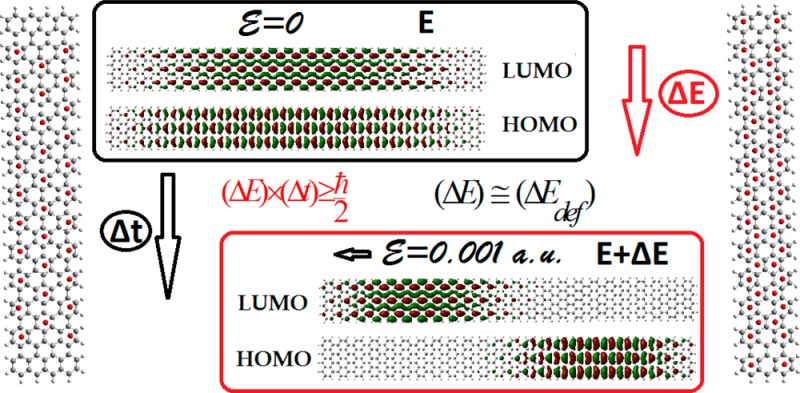
To investigate, interrelate, and correlate all these important (fundamentally and technologically) effects, one needs, similarly to the NICS index for aromaticity, a reliable, simple, quick, transparent, and general index for conductivity or conductance, to quantitatively monitor general trends without the influence of (no matter how strong) particular “details”, such as temperature and defects (of all kinds). Such a project looks at first sight almost impossible. However, it can become more tractable if we consider only perfect samples in zero temperature and evaluate only their inherent “maximum expected” or “ideal” conductivity. Such conductivity would be obtained by calculating an “expected” upper limit of current (and the “maximum” current density) induced by an external electric field of given magnitude in the sense explained below. The simplicity (and transparency) of such “ideal conductivity” calculation (which was one of the prerequisites of the project) is accomplished by the use of the uncertainty principle in the form of the relation
| 1 |
which is usually employed in spectroscopy to determine the natural lifetime of an electronic excited state, or more generally the relaxation time of a process involving ΔE energy changes. As will be illustrated below in section 2.1, based on extensions of the original ideas of Ortiz18by Ramos-Berdullas and Mandado,19−21 (ΔE) in (1), which could be considered as “deformation energy”, can be determined18−21 at the level of second-order perturbation theory from the total energy difference of the “molecular system” with and without an external field. Using this variance ΔE and (1) the lifetime Δt of the “polarized” state is estimated, which can be used to obtain an expression for the upper limit of the current I in terms of the electron charge Δq transferred during the process and the corresponding energy difference:
| 2 |
Then, by determining the “appropriate” charge Δq(here from the induced total dipole moment on the “molecule” in the direction of the field), we can determine the (maximum) current I or current density J⃗ and the (maximum) conductance G or “conductivity” σ from Ohm’s law:
| 3 |
where E is the applied constant
external electric field and V = |E|l; l is the length of the specimen along
the direction of the field. As we can verify from (2) and (3), such
ideal conductance or conductivity, besides a geometrical factor, is
(will be shown to be) given as a product of two factors depending
on the polarizability (through Δq) of the “medium”
and the “mobility” (through ΔE) of the valence electrons, which is physically a very appealing
idea. Such ideal conductance or conductivity, surprisingly enough,
can in some particular cases be correlated to appropriate experimental
measurements15,17 and therefore the results and
the validity of the method can in principle be tested. Thus, with
this simple, transparent, and powerful (as will be proven below) method,
we can not only verify the negative interrelation of conductance or
conductivity and aromaticity in graphene, nanographenes, graphene
nanoribbons, and antidot pattern nanographenes,3,4 but
also to examine and rationalize the variation of these characteristics
(aromaticity and conductance, and band gaps) in terms of length, width,
passivation, and edge morphology. On top of all this, we can further
validate our results by comparing (favorably) with the molecular dependent
conductance15 in representative molecular
junctions and small “molecules” and with the measured
minimum conductivity of graphene, of a few  at 1.6 K.
In what follows, we present and discuss the results of our calculations in section 3, after a brief description of the methodology and computational details in section 2. The results in section 3 are presented in four subsections, including 3.1, 3.2, 3.3, and 3.4, which describe, respectively, (a) the results for “square nanographenes (n × n) consisting of n armchair and n zigzag rings, n = 3–12, (3.1); (b) antidot patterned nanographenes (3.2); (c) armchair nanoribbons of constant width (N = 7, N = 9, and N = 11), based on the 3 × 3, 4 × 4, and 5 × 5 “square nanographenes”, and (d) short molecular chains of the p-xylylene type,20−22 and others.23
2. Methodology and Computational Details
2.1. Theoretical Framework
In the present work, we consider rectangular samples of graphene, nanographenes (with and without antidot patterning), and graphene ribbons of D2h symmetry, which due to symmetry have no net dipole moment without the influence of an external field. When an external electric field is applied the samples are polarized along the direction of the applied field. The conductivity of the “samples”, seen as very large molecules, is calculated through the “relaxing process” of the system from the “polarized” state to the ground state. Clearly, during such process, some electron charge relaxes giving rise to an electron current crossing the entire “molecule” from one edge to the other (from the positive to the negative direction). The magnitude of this charge and the time involved in the process determines the intensity of the current.19 The relaxation occurs when the external potential (field) drops to zero, so that the Hamiltonian governing the process corresponds to the unperturbed Hamiltonian, and the energy changeΔEdef is given by19
| 4 |
where Ψ0 and Ψ are the wave functions for the ground (without the external field E) and “polarized” states (with E), respectively, and ΔEdef stands for the energy relaxation involved in the process seen as deformation energy, in analogy to the deformation energy in perturbation theory. Then ΔEdef is the energy that should be used in the uncertainty relation 1 rather than the energy difference (ΔE) mentioned above. The energy difference (ΔE), the total energy change according to reference,19 is given as a sum of two terms:
| 5 |
where (ΔEdef) stands for the “deformation” of the wave function, and (ΔEelec) is the electrostatic interaction energy between the external electric field and the “polarized” state of the molecule.19 Using the Rayleigh–Schrodinger perturbation theory up to second order, it has been stated in ref (19) that:
| 6 |
The first-order term is zero for nonpolar systems, as in our case. Therefore, one obtains:
| 7 |
Justifying the use of (2) to obtain the (maximum) current (provided we take the absolute value), which, expressing the charge in units of |e| and the energy in eV, we can rewrite in the form:
| 8 |
where the primed quantities of charge, energy, voltage, and length are expressed in units of |e|, eV, V, and Å, respectively. The transverse component of the current density (at the structure’s edges) would be
| 9 |
where a⊥ (or ay) is the length of the structure’s edge perpendicular to the applied external field, along the x direction. The chosen magnitude of the small (in order for perturbation theory to be valid) external field is 0.001 atomic units. Then we obtain the conductivity along the x direction from (9) and (3) as
| 10 |
In the current work, contrary to earlier approaches,18,19 we do not obtain the charge Δq from Mulliken population analysis. Instead, we “measure” the polarization charge Δq in a uniform way from the induced total dipole moment Dx along the x-axis (for external field along the x-axis) at the edges of the rectangular nanographene slabs, Dx = |ax| × |Δq|x, (or |Δq|x = (Dx/ax)), where ax is the total length of the x-edge (in Å). With this definition, Δq corresponds to the minimum charge transfer, compatible with (2). Expressing all lengths in Å and the dipole moment in Debye (1 D = 0.20819434e × Å), we finally obtain
| 11 |
or the following:
| 12 |
Obviously, if we appy the external field in the y direction, we would have
| 13 |
Thus, in addition to a geometrical factor which depends on the total area of the particular nanographene, the conductivity is determined by two terms which are the polarizability of the medium (obtained by the dipole moment D), and the mobility of the electrons determined by the energy difference ΔE.
2.2. Computational Details
As in our previous work on graphene and graphene-based structures,3,4 all DFT calculations (geometries, energies), including the “aromaticity index” of Nucleus Independent Chemical Shifts (NICS)24 have been performed using the Gaussian program package (G09),25 employing the hybrid PBE026 functional and the 6-31G(d) basis set as used in this package. The real space models we used here include most of the nanographene samples we have considered in our previous investigations3,4 (both intact and “holly”), enlarged and extended both in size and morphology. In particular, we have created armchair GNRs of constant widths (so that they are characterized by the same aromaticity type) and variable lengths in order to examine the length dependence of conductivity and band gap. In addition, we have considered a limited representative application to a short molecular chain in order to make contact with existing related work in the literature for different (than graphene) systems.
3. Results and Discussion
3.1. “Square” n × n Nanographenes
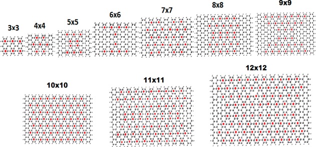
The structure and aromaticity patterns of “square” nanographenes n × n, n = 3–12 are shown in Figure 1. For some of them (n = 3–10), the aromaticity and aromaticity patterns have been already examined in our previous work3,4 (n = 2–9 in ref (3), n = 10 in ref (4)). With the addition of two larger nanographenes, we can further verify the periodicity of the aromaticity patterns described earlier.3 We can clearly see that all nanographenes with
| 14 |
are Clar type characterized by the circumcoronene CIRCO aromaticity pattern (N = 0 corresponds to benzene). In fact, by comparing to the full range of structures discussed in ref (4), we can see that it is enough to have just the number of zigzag rings nZ satisfying relation 14 (i.e., nZ = 3N + 1, as will be verified in section 3.3).
Figure 1.
Structure and aromaticity pattern of the “tetragonal” n × n, n = 3–12, nanographenes.
From the structures shown in Figure 1, only 4 × 4, 7 × 7, and 10 × 10 satisfy relation 14, and they are all of Clar (CIRCO) type. These structures can be characterized as “more aromatic than the rest”. As we have explained before,4 and as we will also see further below (in section 3.3), the relation 14 for the CIRCO pattern actually refers to the number of zigzag rings. Therefore, the CIRCO pattern can appear for variable number of armchair rings provided the number of zigzag rings obeys (14). In Table 1, we have summarized the “conductivities” and LUMO–HOMO gaps of the “square” nanographenes of Figure 1. It should be emphasized that the number of significant digits in Table 1 does not necessarily reflect the real accuracy of the method, but is meaningful for relative comparisons. With this in mind, we can clearly see immediately from Table 1 that the conductivity in the (horizontal) x direction, connecting the zigzag edges is much larger (sometimes by an order of magnitude), compared to the (vertical) y direction connecting the armchair edges. This is in full agreement with our predictions3 that the region around the armchair edges is more aromatic in comparison to the region around the zigzag edges (which is the least aromatic), as well as the negative correlation of aromaticity and conductivity. However, the variation of “conductivity” with size (in the region of sizes of Table 1) does not depend very much on the aromaticity pattern, something which is more or less true for the LUMO–HOMO gaps as well. Instead, conductivity is monotonically increasing for both directions but significantly much faster in the x (zigzag) direction; however, at the same time, the average LUMO–HOMO gaps decrease. Clearly, those two quantities are (negatively) interrelated. Besides quantum confinement and edge effects, which are also responsible for the almost monotonically decrease of the LUMO–HOMO gap in the same region of sizes, a prevailing effect (which is not independent of the other two) for conductivity is indirectly related with the size of the “samples” in the following sense: For a perfect atomically precise periodic structure (no defects, no impurities) with zero or very small gap, at zero temperature, the ideal conductivity (or conductance) will tend to infinity for the infinite structure. For finite (locally periodic or nonperiodic) structures, the conductivity, would be expected to increase with size, because the corresponding infinite structure would have zero (or very small) gap and no edge effects.
Table 1. Size (x-Length, y-Length in Å) Dependence of the Calculated
Conductivities along the Perpendicular (σx) and Parallel (σy) Directions
to the Zigzag Edges in Units of  , Together with the LUMO–HOMO (L–H)
Gap in eV for “Tetragonal” n × n Nanographenes, n = 3–12.
| structure | x-length (Å) | y-length (Å) |  |
 |
L–H (eV) |
|---|---|---|---|---|---|
| 3 × 3 | 13.566 | 9.211 | 0.03 | 0.01 | 1.24 |
| 4 × 4 | 17.818 | 11.682 | 0.11 | 0.02 | 0.32 |
| 5 × 5 | 22.081 | 14.134 | 0.22 | 0.04 | 0.19 |
| 6 × 6 | 26.345 | 16.594 | 0.39 | 0.05 | 0.15 |
| 7 × 7 | 30.601 | 19.057 | 0.40 | 0.14 | 0.31 |
| 8 × 8 | 34.869 | 21.510 | 0.44 | 0.19 | 0.36 |
| 9 × 9 | 39.126 | 23.971 | 1.127 | 0.27 | 0.35 |
| 10 × 10 | 43.377 | 26.433 | 2.60 | 0.45 | 0.15 |
| 11 × 11 | 47.580 | 28.914 | 3.83 | 0.57 | 0.09 |
| 12 × 12 | 51.908 | 31.390 | 4.66 | 0.76 | 0.14 |
Thus,
for a very small structure with a large gap and a short (or
no) “local periodicity” and nearby “edges”
like a small nanocrystal or molecule, which are nonperiodic, the finite
“molecular dependent DC conductivity” (or, better “conductance”)
will tend to zero, as the size of the system tends to zero. Likewise
when the size (length in the direction of the field) becomes larger
and larger, the corresponding ideal conductivity will tend to infinity.
As we see in Table 1, this is true. As a matter of fact, the values of 0.01 and 0.03 (or 5 × 10⁻³G0 and 1.5 × 10⁻²G0 where
  is the quantum of conductance)
for the
3 × 3 structure, are consistent with the experimental values
of Chen et al.15 (10–3G0, 10–5G0) for the molecular dependent conductance they measure
in their samples. Let as call this effect for brevity “the
size effect”. It becomes clear therefore that the size effect
(which includes quantum confinement) is the dominant effect for the
structures of Table 1.
For the LUMO–HOMO gaps, which do not always fully correlate (inversely) with “conductivity” or aromaticity, the “size effect” is practically equivalent to the quantum confinement effect. Therefore, although our results fully confirm the anisotropy of conductivity in the two (zigzag and armchair) directions, which is a very significant effect, they do not show any striking difference for the various aromaticity patterns (which is also true for the LUMO–HOMO gaps), due to the size effect. In section 3.3, in which we consider armchair nanoribbons of very large lengths, we can verify the dependence of conductivity on the aromaticity type and pattern.
3.2. Antidot Patterned Nanographenes
In this section, we consider antidot patterned nanographenes, with structures and aromaticity shown in Figure 2a,b and Figure 3a–d, whereas the electronic characteristics (conductivity and LUMO–HOMO gaps) are summarized in Table 2. Figure 2a shows the structures and aromaticity patterns of the 6A × 8Z intact (1), and “holly” with 4 and 6 holes, respectively (in 2 and 3). As we can see in Figure 2a, because the aromaticity pattern is determined by the number of zigzag rings, the aromaticity pattern of 1 is the same as the one of 8A × 8Z in Figure 1. At first sight, the aromaticity patterns of the antidot structures (and in particular of the 4 holes) are “more aromatic” than the ones of the intact structure (more Clar- or CIRCO-like), and therefore, we would expect the “holly” structures to have a lower conductivity, which clearly contradicts the results of Table 2.
Figure 2.
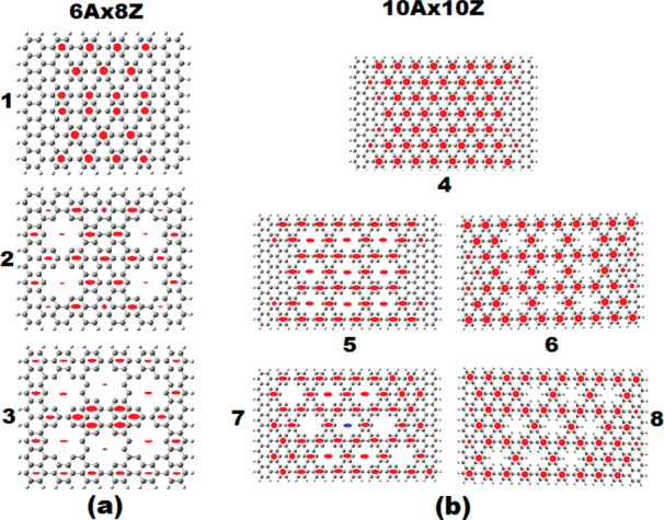
Geometrical and aromatic structure (aromaticity patterns) of the antidot patterned 6A × 8Z (a) and 10A × 10Z (b) nanographenes.4,5 Solid red circles indicate π aromaticity. Full red ellipses denote σ aromaticity, whereas the blue ellipse signifies σ antiaromaticity. The intact structures are shown in (1) and (4), respectively. The 4 and 6 holes 6A × 8Z antidots are shown in (2) and (3). The 9 orthogonal 10A × 10Z nonpassivated (5) and passivated (6) antidots are shown in (5) and (6), respectively, whereas the corresponding 9 nonorthogonal 10A × 10Z antidots are shown in (7), (8).
Figure 3.
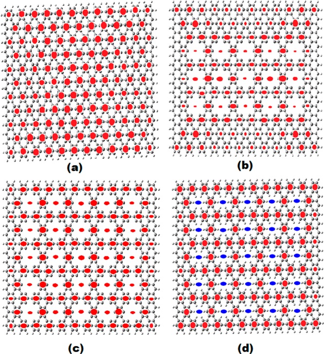
Geometrical and aromatic structure (aromaticity patterns) of the antidot patterned 16A × 12Z nanographenes. The intact structure is shown in (a), and the 15 antidots patterned (nonpassivated) 16A × 12Z structure in (b). The 25 antidot structures (non-, and fully-) passivated structures are shown in (c) and (d) respectively.
Table 2. Size (x-Length, y-Length in Å) Dependence of the Corresponding
Conductivities
along the Perpendicular (σx) and
Parallel (σy) Directions to the
Zigzag Edges in Units of  , Together with the LUMO–HOMO (L–H)
Gap in eV, for Dots (in Bold) and Antidots (with Holes, h); Non-Passivated
(Underlined), and Fully Passivated (Normal Font, No underline)a.
| structure | x-length (Å) | y-length (Å) |  |
 |
L–H (eV) |
|---|---|---|---|---|---|
| 6A × 8Z | 26.438 | 21.397 | 0.28 | 0.18 | 0.110 |
| 4 holes no hydrogen | 26.438 | 21.397 | 0.44 | 0.16 | 0.165 |
| 6 holes no hydrogen | 26.438 | 21.397 | 0.44 | 0.17 | 0.111 |
| 10A × 10Z | 43.320 | 26.454 | 2.60 | 0.45 | 0.147 |
| 9 holes orthogonal no H | 43.320 | 26.454 | 11.10 | 4.09 | 0.022 |
| 9 holes oblique no H | 43.320 | 26.454 | 2.46 | 0.51 | 0.090 |
| 9 h orthogonal with H | 43.320 | 26.454 | 2.61 | 0.45 | 0.084 |
| 9 h oblique with H | 43.320 | 26.454 | 2.85 | 0.48 | 0.100 |
| 12A × 16Z | 51.980 | 41.334 | 4.99 | 1.86 | 0.170 |
| 15 h no hydrogen | 51.980 | 41.334 | 4.79 | 2.65 | 0.114 |
| 25 h no hydrogen | 51.980 | 41.334 | 4.87 | 2.05 | 0.090 |
| 25 h with hydrogen | 51.980 | 41.334 | 5.29 | 1.33 | 0.072 |
Results are given with three decimal points (in particular, for conductivity and LUMO–HOMO gaps) for comparison purposes.
A closer look, however, reveals that the CIRCO pattern in 2 (and in part in 3), and in fact the whole aromatic pattern, is of σ type, which is often encountered in metallic compounds.27 Therefore, we can assume that σ type aromaticity, contrary to π type, can be associated (at least in periodic graphene dots and antidots) with higher (not lower) conductivity.
This is emphatically verified by the results for the 10A × 10Z antidots in Figure 2b, in which the nine-orthogonal-antidots (with no H passivation), structure 5, with fully CIRCO (Clar) σ type pattern, corresponds to the higher conductivity (11.10 e2/h) found so far in this work for dots and antidots. This is true not only for the σx conductivity along the x direction, connecting the zigzag edges but also for the σy conductivity along the y direction, which also obtains its largest value of 4.1 e2/h. This structure has also the smallest LUMO–HOMO gap from all structures in Figure 2a,b and Figure 3a–d, verifying the strong dependence of the conductivity on the LUMO–HOMO gap. The related structure of nine-oblique-antidots (with no H passivation) in 7 has much lower σx conductivity (2.5 e2/h). This can be attributed to its much lower σ and higher π aromaticity. As we can see in Figure 2b, the aromaticity pattern in 7 includes two rather large regions of pure π-aromaticity of Clar (CIRCO) pattern in the upper right and lower left regions. Moreover, the central ring (and others to a lesser degree) is (are) σ antiaromatic (the central ring is characterized by NICS(0) = +36.2 ppm, and NICS(1) = +28.4 ppm),4 thus reducing further the σ aromaticity. Computationally, the big difference between orthogonal and oblique holes is due to the mobility term, which is by a factor of 4 larger; however, the polarizability term is practically the same for both sets of holes. The corresponding fully passivated 9 hole-10A × 10Z nanographenes in 6 and 8, which, according to our earlier work are expected to behave similarly to the intact structure,5 have indeed similar conductivities to the “mother structure” and to each other. This is also true for the fully passivated 25-hole 12A × 16Z antidot structure in Figure 3d, which more or less has the same (slightly larger) conductivity with the intact structure, but smaller LUMO–HOMO gap. Similarly, the 15 and 25 antidots patterned non passivated 16A × 12Z structures in Figure 3b,c have practically the same (slightly smaller) conductivity with the intact structure. For the 15 antidots patterned 16A × 12Z structure, this could be understood in view of the large π CIRCO aromaticity regions around the holes (and particularly near the corners), as can be seen in Figure 3b. However, for the 25 antidots in Figure 3c, this low conductivity value (0.49e2/h) seems indeed to be a puzzle in view of the large conductivity value(s) of the 9 orthogonal 10A × 10Z holes in 5 (Figure 2b). A simple understanding can be obtained by considering the stability of this structure, which is fully covered by holes serving as theoretical model of the graphene antidot lattice. This structure in reality should be unstable and, in fact, “σ unstable”, because the instability mainly concerns the sp2 bonding. Therefore, σ instability is (should be) associated with σ antiaromaticity, which, however, does not show up in the aromaticity pattern of Figure 3c. If there is any hidden σ antiaromaticity, the most obvious place to reside in would be the dangling bonds in the holes’ rims. Then, to uncover such hidden antiaromaticity, we need to place “aromaticity sensors” (i.e., dummy atoms on which we calculate the NMR chemical shifts, as is explained in ref (4) and as is illustrated in Figure 1 of that work) in the antidot’s rims. Indeed, by placing such “aromaticity sensors”, we uncover very high σ antiaromaticity with positive NICS(0) values as high as +22.5 ppm, with corresponding NICS(1) values about +8.0 ppm, all over the peripheral holes, and slightly smaller values (NICS(0) = +17 ppm) for the more central holes. Thus, this “hidden” up to now σ antiaromaticity can account for the much smaller value of the conductivity in the 25 12A × 16Z antidots of Figure 3c, compared to the one of 9 orthogonal 10A × 10Z antidots in 5 of Figure 2b. For comparison, similar tests for “hidden antiaromaticity” have been performed for the 9 orthogonal non passivated 10A × 10Z antidots with negative results. Positive NICS(0) values at the rims of only around +4.5 ppm were found, only for the 4 rings close to the corners, but even in this case, the NICS(1) values were negative but small (around −2 ppm), both in the limit of nonaromatic values. Thus, the initial observation that high σ aromaticity, contrary to π, is associated with high conductivity values seems to be consistent and valid in all cases examined here.
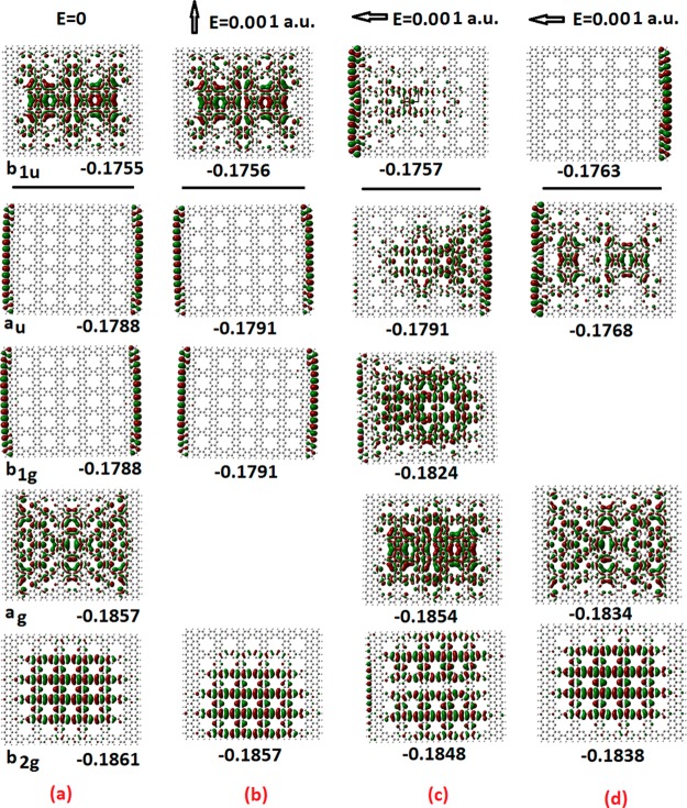
To get even more physical insight in the “molecular” conduction process, we have plotted in Figure 4 the frontier molecular orbitals of the 25 12A × 16Z antidots of Figure 3c before and after the application of a constant electric field, both in the “vertical” (armchair) and “horizontal” (zigzag) directions. The physical picture emerging from Figure 4 is very appealing and important both scientifically and pedagogically. As we can see in this figure, electronic charge moves (shifts) in the opposite direction of the applied field for the occupied electronic states, as is expected. For the nonoccupied orbitals (LUMO in this case), the electronic density shifts in the direction of the applied field (as for “positive charge”), illustrating the presence of “holes” in the “conduction band”, familiar from the band theory of solids. Moreover, for the excited state in (d), we can see that the opposite happens: The charge distribution of occupied orbitals shifts in the direction of the applied electric field, whereas for nonoccupied orbitals, the shift is in the opposite direction of the applied field. We can interpret this as a “negative polarizability” example, which could have far-reaching implications for technological innovations in particular for metamaterials, such as left-handed optical materials.28
Figure 4.
Frontier orbitals of the 25 antidots patterned 12A × 16Z nanographene without external field (a) and with external electric field in the vertical (b) and horizontal (c,d) directions. The results in (d) correspond to a slightly different excited state induced by the field. The numbers below the orbital plots indicate their (orbital) energies (in hy). For the zero-field case, the symmetry of the orbitals is also shown together with the orbital energies. The horizontal lines separate occupied and nonoccupied orbitals.
3.3. Armchair Nanoribbons
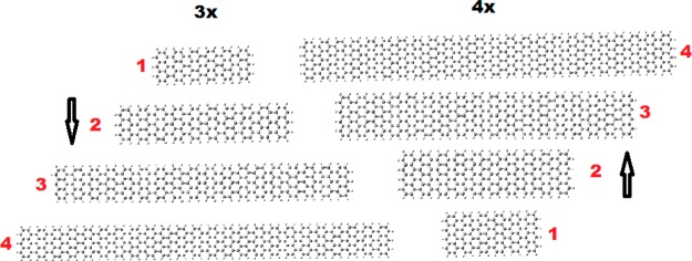
As was explained earlier, the CIRCO (Clar type) aromaticity pattern appears in rectangular nanographene samples every time the number of zigzag rings satisfies (14). Therefore, armchair ribbons of constant width (number of zigzag rings) at their edges would have the same type of aromaticity pattern independently of their length. Thus, it is very important (for their functionalization) to examine the length variation of conductivity and band gap for particular widths. Such length-dependent study is very scarce (if any) in the literature of GNRs, which are almost always considered to have infinite lengths, although recently, atomically precise GNRs synthesized from molecular precursors29−31 have finite lengths, sometimes of few nanometers (30–100 Å). This might lead to some misleading conclusions in comparison of theoretical (infinite length) and experimental results. In the present work, we use well-defined finite atomic models, and therefore, we can examine, in addition to the width variation which is usually examined in the literature, both width and length variation. As a result, our “samples” are characterized by both lateral and longitudinal quantum confinement. The GNRs we have examined here are based on “lateral” extensions of the 3 × 3, 4 × 4, and 5 × 5 “tetragonal” nanographenes of Figure 1 (considered in section 3.1) with representative characteristic aromaticity patterns. These GNRs in conventional notation, according to which an armchair ribbon is specified by the number of carbon atoms forming its width, correspond to widths specified by N = 7, 9, and 11, respectively. In Figure 5, we show the structures of some representative GNRs based on the 3 × 3 and 4 × 4 dots (of widths 7 and 9 respectively), skipping the 5 × 5 (N = 11) ribbon for space economy. As was explained earlier, these GNRs (N = 7, 9, 11) are characterized by unique aromaticity patterns, with the 4 × 4 (N = 9) corresponding to the full CIRCO (Clar) aromaticity pattern.
Figure 5.
Representative structures of the 3× and 4× GNRs, of width N = 7 (9.2 Å) and N = 9 (11.7 Å), respectively, and lengths of 26.5 Å (1), 43.6 Å (2), 77.8 Å (3), and 103.6 Å (4), respectively.
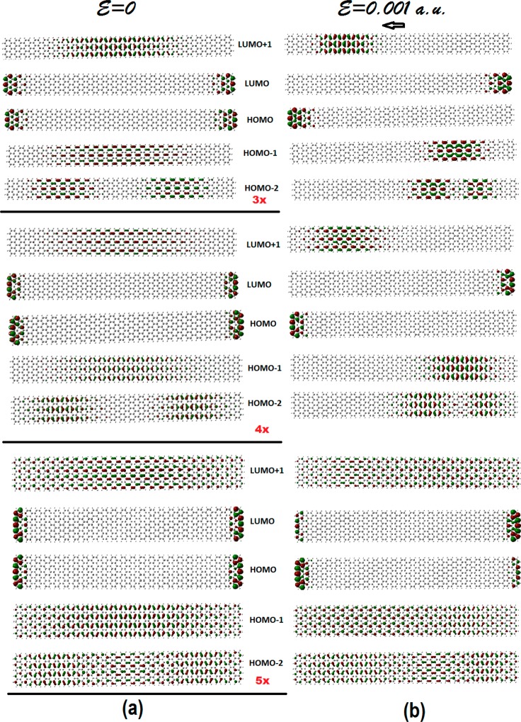
These characteristic aromaticity patterns, which do not depend on the length but only on the width, are shown in Figure 6 for a typical length of 13 armchair rings, which is roughly equal to 56.5 Å. It is interesting to observe the 3× aromaticity pattern (corresponding to the 3 × 3 pattern of Figure 1), which is reminiscent of the coronnene (CO) pattern,3,4 in this type of ribbon geometry. This is highly suggestive that in rectangular geometry (in analogy to the hexagonal one), we also have two main aromaticity patterns, which correspond to the following: (1) the Clar-type CIRCO pattern, for N= 9 or N = 3p, p = 3, 5, 7,... (or 3n + 1 zigzag rings, n = 1, 2,...), characterized by large gaps and high “local” (nonglobal) aromaticity; (2) the CO pattern for N = 7 or in general N = 3p + 1, p = 2, 4,...(or 3n zigzag rings) associated with migrating sextets and characterized also by relatively large gaps. The third pattern, corresponding to 5, or in general 3n + 2 zigzag rings of widths N= 5, 13, or N = 3p + 2 (p = 1, 3,...), is a mixture of the two characterized in general by very small band gaps. Loosely speaking, if the two main cases correspond to large-scale behavior resembling insulators and semiconductors, the third mixed pattern corresponds to conductor or metallic behavior. In this respect, we should recall3 that graphene itself is also a mixture of the two patterns but in a completely different way, in which the two forms coexist. In Figure 7, we show the frontier orbitals of the three representative structures of Figure 6, before and after the application of the external electric field.
Figure 6.
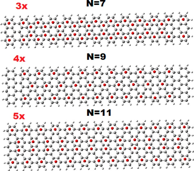
Characteristic aromaticity patterns of representative armchair GNRs of widths N = 7, 9, and 11, respectively, and constant length of about 56.5 Å (13 armchair rings).
Figure 7.
Frontier orbitals of the different width: 3× (top), 4× (middle), and 5× (bottom) armchair GNRs, with constant length of about 103.6 Å; before (a), and after (b), the application of an external electric field of magnitude 0.001 au and horizontal direction from left to right.
As we can see in Figure 7, both HOMO and LUMO orbitals for all three structures correspond to edge states, while the HOMO–1 and LUMO+1 are delocalized in the central region for the 3× and 4×, and in the whole ribbon for the 5× structure.
Thus, the HOMO–1 and LUMO+1 could be considered as gap-determining HOMO and LUMO orbitals (HOMO*, LUMO*), because their overlap, in contrast to the one of the HOMO/LUMO pair, is quite substantial. These effective band gaps should be considered as the predicted band gaps of the present study. Thus, the predicted band gap for the N = 7 GNR is 2.7 eV in very good agreement with the measured value30 of 2.5 ± 0.2 eV (2.3–2.7 eV). However, this value is in clear disagreement with the theoretical predictions based on DFT/LDA approach with (3.7 eV too small) and without (1.6 too big) sophisticated many-body corrections through the GW method, so that the difference was attributed to the presence of the gold substrate.30 In this work, it is shown that this value reflects the properties of the free N = 7 GNR. Therefore, the predicted band gaps for the N = 9 and N = 11 armchair GNRs (for which, as far as we know, no available experimental data exist up to now) should be about 1.75 and 0.45 eV, respectively; however, the predicted values in the literature31 are 2.0 and 0.90 eV, respectively (with GW many body corrections), or 0.7 and 0.2 eV without such many-body corrections (see ref (31), in particular, supplementary Figure 6). As we can see, the N = 11 GNR, which is of the N = 3p + 2 type (p = 3), has the smallest gap (is expected to be metallic). This is consistent with the aromaticity/gap rules.3,8−10
Based on our previous work3 and related literature,8−10 we would expect that the 4× (N = 9) nanoribbon would have the largest gap and the smallest conductivity, σx (along the nanorribon axis, x), from the other two for a given length, large enough to avoid or minimize (longitudinal) quantum confinement. As we can see in Table 3 and the associated Figure 8a,b, showing the conductivities and the LUMO–HOMO gaps, the results are not exactly as was expected. First of all, we can see that for the shortest GNRs, of 3 armchair rings long (about 9.2 Å), the conductivity is of the order of 10–2G0, an order of magnitude larger than the experimental measurements of the molecular-dependent conductance of Chen et al.15
Table 3. Length (Lx) Dependence (in Å) of the Conductivity
σx along the Length of the GNR in
Units of  (in Bold), and LUMO–HOMO Gaps in
eV, for Various Constant Width (Ly) Armchair GNRs Consisting of n (n = 3, 4, 6, 8, 10, 13, 18, 20, 24)× Armchair Rings along the x-axis (Perpendicular to the Zigzag Edges) and m (m = 3, 4, 5) Rings along Their Width, with Widths
about 9.2 Å (3 Rings, 3×), 11.7 Å (4 Rings, 4×),
and 14.1 Å (5 Rings, 5×), Respectively.
| 3× | 4× | 6× | 8× | 10× | 13× | 18× | 20× | 24× | ||
|---|---|---|---|---|---|---|---|---|---|---|
| GNR width (Ly)/Å | properties | Lx/Å | Lx/Å | Lx/Å | Lx/Å | Lx/Å | Lx/Å | Lx/Å | Lx/Å | Lx/Å |
| 13.6 | 17.9 | 26.5 | 34.9 | 43.6 | 56.5 | 77.8 | 86.5 | 103.6 | ||
| 3× Ly = 9.2 |  |
0.03 | 0.08 | 0.37 | 1.04 | 2.31 | 5.88 | 18.53 | 26.66 | 53.20 |
| L–H(eV) | 1.239 | 0.729 | 0.263 | 0.144 | 0.102 | 0.074 | 0.051 | 0.046 | 2.68a 0.037 | |
| 4× Ly = 11.7 |  |
0.04 | 0.11 | 0.38 | 1.01 | 2.15 | 5.27 | 16.04 | 22.94 | 45.16 |
| L–H (eV) | 0.589 | 0.320 | 0.169 | 0.119 | 0.093 | 0.070 | 0.049 | 0.044 | 1.75a 0.037 | |
| 5× Ly = 14.1 |  |
0.04 | 0.11 | 0.39 | 1.11 | 2.19 | 5.28 | 16.62 | 24.54 | 48.93 |
| H–L (eV) | 0.386 | 0.254 | 0.156 | 0.114 | 0.090 | 0.068 | 0.049 | 0.044 | 0.45a 0.037 |
The underlined numbers in the last column correspond to the gap-defining (“effective”) LUMO–HOMO gaps (i.e., the gaps between HOMO–1 and LUMO+1 in the present case, see text).
Figure 8.
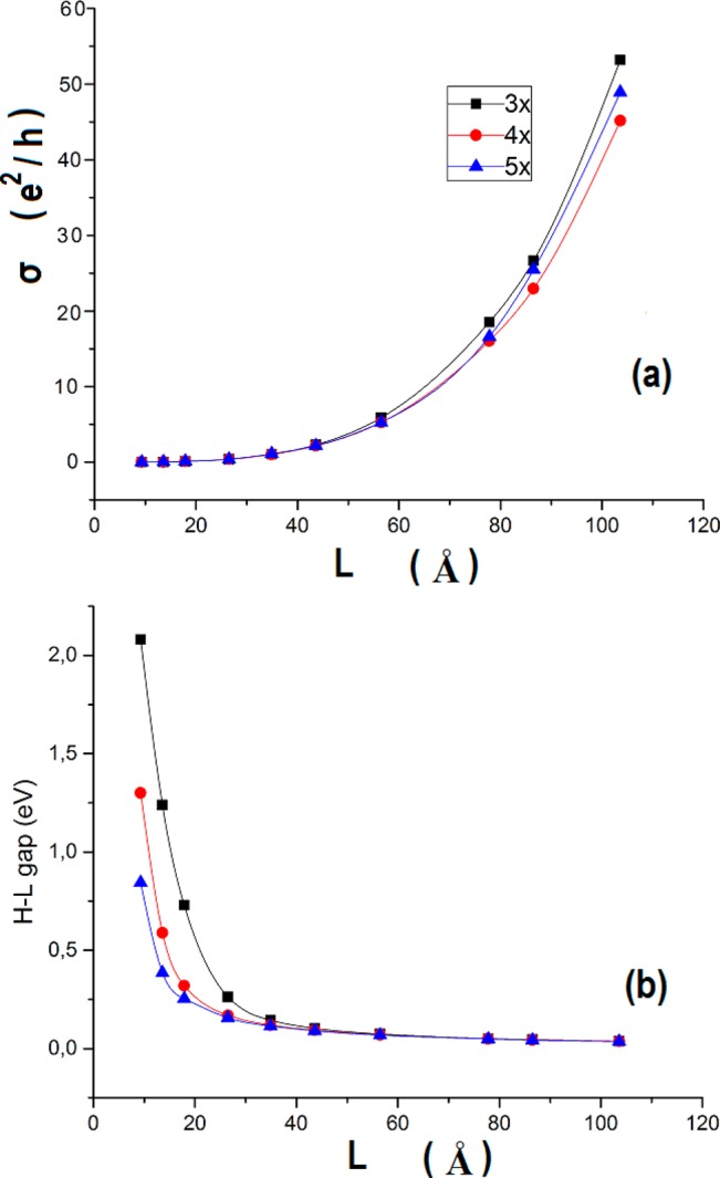
Length dependence of the “conductivity” (a), and HOMO–LUMO gap (b), across the zigzag edges of narrow armchair GNRs of width 3× (N = 7), 4× (N = 9), and 5× (N = 11), shown with solid squares, circles, and triangles, respectively. Solid lines correspond to best spline fits along the calculated data points. The electric field is applied along the length direction (joining the zigzag edges) of the AGNRs.
For larger samples, of the same width the conductivity increases monotonically, reaching several tens of G0, for about 103.6 Å (24 armchair rings), fully consistent with the measured “minimum conductivity” of graphene.17
Yet, such variation of the conductivity is totally unexpected, because measured conductivities are known31 to (exponentially) decrease with length (if length of the specimen is much larger than the localization length), although there are clear cases in molecular wires shown increased conductivities for the longest samples.20,32 On the other hand, for the ideal samples of Table 3, in which the LUMO–HOMO gaps monotonically decrease, and the prevailing scattering is at the zigzag edges, the ideal conductivity is naturally increasing monotonically with length.
For samples of the same length, the conductivity remains practically the same (with marginal increase) with increasing width, for relatively small lengths up to about 56.5 Å. For larger lengths, the variation is not monotonic. The conductivity of the more aromatic GNR (4×, N = 9) decreases, in relation to both 3× (N = 7) and 5× (N = 11). This is in agreement to what would be expected according to the aromaticity-gap rules. On the other hand, the LUMO–HOMO gaps, dominated by quantum confinement, constantly decrease (much more rapidly than the conductivity increase) with both width and length, saturating for large lengths (around 100 Å) to the value of 0.04 eV, close to the expected limit for graphene. In this case, the expected aromaticity/gap rule is not operative because of quantum confinement (both lateral and longitudinal) and, in part, edge effects. However, even after we have accounted for edge effects by introducing gap-defining HOMO, LUMOs, according to the charge distribution of Figure 7, the LUMO–HOMO gaps (underlined in the last column of Table 3), decrease monotonically with increasing width (for constant length, of about 103.6 Å), due to reduction of (lateral) quantum confinement. Nevertheless, as is illustrated emphatically in Figure 8a and corroborated in Table 3, the conductivity of the most aromatic GNR, of width N = 9, is the lowest of all three, at large enough lengths. Thus, the aromaticity/gap rule should in fact be replaced by the aromaticity/conductivity rule.
Besides the aromaticity/gap rule which describes the largest expected gap in GNRs (and not only), the rule for the minimum/metallic gap, according to which GNRs of widths N = 3p + 2 (p = 3 here) should have the smallest gap (be metallic), is still valid irrespectively of the monotonic gap decrease with N, since the N = 11 GNR has indeed the smallest gap, as was expected. To test whether or not this is accidental (due to the monotonic decrease from N = 7 up to N = 11), we need to compare with the N = 13 case. To this end, we have run a single representative calculation for one N = 13 GNR of length about 52 Å, which is inside the range of lengths of the experimental samples (30–110 Å). We should emphasize that the N = 13 armchair, similarly to the N = 7 GNR, is a challenge for the theoretical study because the theoretically predicted gap is 2.4 eV, whereas the experimentally measured gap is only 1.4 eV.29 This discrepancy was attributed to image charge screening due to the gold substrate29 (similarly to the N = 7 GNR). In addition Chen et al.29 have discovered another inconsistency with theory in that the experimental LDOS of the N = 13 armchair GNR conduction and valence band edge states are strongly localized along the edges of the ribbon, similarly to the N = 7 case,33 in clear disagreement with the spatially extended nature of the band edge states theoretically predicted for isolated armchair GNRs.29Figure 9 summarizes the results of our calculations for the N = 13 armchair GNR. As we can see in Figure 9, our results are fully consistent with the experimental data in both respects: band gap and zigzag edge states. This is true also for the N = 7 GNR, as we can verify from Figure 7 and Table 3. According to our results, the edge-localized nature of the HOMO and LUMO orbitals seems to be an important general trend for noninfinite armchair GNRs. As a matter of fact, the finite length of the recently synthesized atomically precise GNRs should be the main reason for the large theoretical discrepancies with respect to the band gap, as well as the localization of the band edge states.
Figure 9.
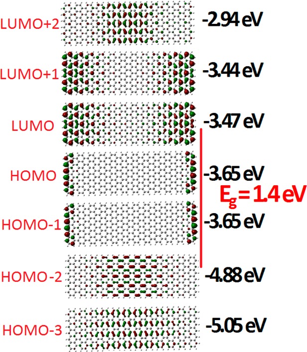
Frontier orbitals and orbital energies of the N = 13 armchair GNR. The vertical red line connects the gap-defining HOMO and LUMO orbitals (HOMO*, LUMO*) and marks the (“effective”) band gap, Eg.
According to our results, the contribution of the gold substrate is not as important for the observed band gaps as was believed up to now. With our simple methodology we can get excellent agreement with experimental bang gaps and band edge states for free-standing GNRs.
3.4. Short Molecular Chains
In this section, we extend and test the application of the present approach, besides graphene and graphene-based systems, to some representative molecular systems, such as the polycyclic aromatic hydrocarbon perylene, and a few characteristic short molecular chains of the p-xylylene type in order to make contact and compare with relevant calculations in the literature.20−23
Unlike perylene (and the graphene structures examined before), the molecular chains are not homogeneous because they include “junctions” (virtual “electrodes”) of gold atoms. In addition some of the above structures, (b) and (d), are not fully planar. All these can introduce some additional uncertainties in the results, which however are not important for the present purposes because we are interested in order of magnitude estimates. The conductivity and gap results are summarized in Table 4. As we can see in Table 4, the magnitude of the molecular-dependent conductivity is in full agreement with the results of Chen et al.,15 who have obtained values between 10–3 and 10–5 G0 for the molecular junction conductance.
Table 4. Conductivity (in 10–3 G0) and LUMO–HOMO Gaps (in eV), Together with NICS(1) Values (in ppm) for the Molecules of Figure 10a.
| structure | conductivity 10–3G0 | L–H gap (eV) | NICS(1) (ppm) |
|---|---|---|---|
| perylene | 1.6 (x), 0.9 (y) | 3.30 | –9.7 |
| (a) | 1.8 | 4.42 | –9.7 |
| (b) | 2.7 | 3.35 | –8.3 |
| (c) | 7.0 | 2.55 | –2.4 |
| (d) | 2.7 | 4.01 | –10.2 |
| (e) | 23.5 | 1.93 | –2.9 |
Our results are also in agreement with the measurements of Xu et al.,32 who have studied charge transportin oligothiophenes with three and four repeating units and observed increasing conductance with increasing molecular length. In addition, our results concerning the relative conductivities of the p-xylylene molecular chains and their variation with length for odd and even gold linking atoms, as in Figures 10a–e, are in full agreement with those of Mandado et al.,20 obtained by different techniques. Indeed, our data (see Table 4) clearly show that the chains in Figure 10c,e are much better electronic conductors compared to the rest in Figure 10, consistent with the fact these structures have the lowest aromaticity index NICS(1). This finding, that is, the much higher conductivity of the chains in Figure 10c,e, is in full agreement with the conclusions of Mandado et al.20 Moreover, Mandado and collaborators,20−22 applying different finite bias voltages (between 0 and 5 V), were able to further examine the response of these chains to the influence of the external electric field in both aromaticity (electron delocalization within the rings) and conductivity. They found that the structure in Figure 10c not only has a much higher conductivity compared to those in Figure 10a,b but also its response to the external electric field is completely different compared to the other two in Figure 10a,b. In Figure 10c, the applied voltage results in an increased electron delocalization within the rings together with a larger electron transfer, in contrast to the structures in Figure 10a,b, where the same voltages partially destroy the electron delocalization. Mandado and collaborators,20−22 in accord with earlier work by Morikawa et al.,23 have extended these ideas and rationalized their results in terms of the “polarized valence bond”. They have concluded that if the effect of the applied voltage is to destroy aromaticity, then the resulting conductance decreases with aromaticity. If, on the other hand, the effect of the applied voltage is to reinforce aromaticity, then conductance could be in principle reinforced as well. Clearly, such effects dealing with inhomogeneous polarized valence bond structures are not directly connected with the present work.
Figure 10.
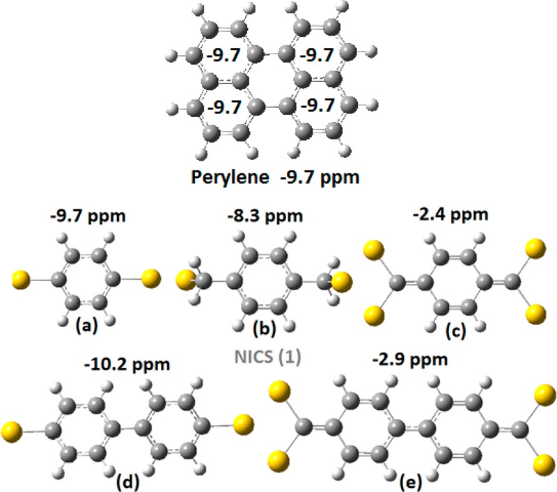
Geometry and aromaticity (given by the NICS(1) values in ppm) of perylene (top) and five (a, b, c, d, e) very short molecular chains of the p-xylylene type, with gold junctions.
4. Conclusions
We have adopted and developed a simple, transparent, and powerful method for evaluating the DC conductivity of various rectangular nanographene samples, with and without antidot patterning, at zero temperature using ground-state DFT calculations with and without external electric field for the calculation of the charge accumulation and the estimation of the characteristic time through the uncertainty relation. Besides a geometrical factor which depends on the total area of the samples, the size- and edge-dependent conductivity is given as a product of two terms, which correspond to the mobility of the electrons (determined energetically through the uncertainty relation), and the polarizability of the medium (determined from the total dipole moment, induced by the external field). This allows a clear and general microscopic picture and understanding not only for the electronic and transport properties of the various nanographenes but also for the variation of these properties in terms of spatial direction, size, edge morphology, as well as antidot patterning and passivation. As would be expected, in the limit of very small samples, the conductivity (been mainly a “solid state” property based on an infinite lattice) becomes small, whereas for much larger periodic samples, it tends to infinity. Obviously, for narrow GNRs, the size (length) dependence can prevail over the directional (armchair versus zigzag) effect. Furthermore, on the basis of our calculations:
-
(1)
We verify and generalize the experimental findings that aromaticity and conductivity vary in an opposite way (the higher the aromaticity of the “molecule”, the lower its conductivity and vice versa).
-
(2)
However, this is true only for π aromaticity. For σ aromaticity (commonly encounter in metallic compounds27), in general the opposite would be expected, in particular for extended periodical structures.
-
(3)
We predict and verify numerically that conductivity in rectangular (nano)graphene samples with both armchair and zigzag edges is anisotropic; with the conductivity along the direction connecting the zigzag edges (in other words, perpendicular to the zigzag edges) being much higher (sometimes by 1 order of magnitude) compared to the direction connecting the armchair edges, which, as we have shown earlier, are much more aromatic compared to (the region around) the zigzag edges.
-
(4)
It is shown that both mobility and polarizability contribute to this anisotropy.
-
(5)
GNRs of proper length, which are Clar aromatic (or else “more aromatic”) have comparatively lower values of conductivity, although their LUMO–HOMO gaps could be lower, in relation to non-Clar GNRs of the same length. Thus, the “conductivity criterion” presented here could be much safer compared to LUMO–HOMO gap comparisons.
-
(6)
The predicted band gaps for armchair GNRs of widths N = 7, 13 are in excellent agreement with the corresponding experimentally measured band gaps. This is extremely important in view of the gross failure of more sophisticated methods. Although the failure was attributed to charge screening from the gold substrate, we have found with very good accuracy the measured band gaps for free-standing atomically precise GNRs. We attribute the existing discrepancies of earlier theoretical work with experiment to the finite length of such GNRs. For the N = 9 and N = 11 armchair GNRs for which, to our knowledge, there are no experimental measurements of the gap up to now, our predicted band gaps are 1.75 and 0.45 eV, respectively, in clear disagreement with the theoretical predictions in the literature. Future experimental data would probably test these values.
-
(7)
In full agreement with experimental measurements, and contrary to existing theoretical work, we demonstrate that the valence and conduction band edges of such armchair GNRs are spatially localized at the zigzag edges at both ends of the GNRs.
-
(8)
Antidot patterning, contrary to what would be expected on the basis of defect states, can significantly increase the conductivity, by altering both the mobility of the electrons and the polarizability of the medium.
-
(9)
The larger increase in the conductivity by antidot patterning in our present work was observed for not passivated antidots, which are characterized by σ aromaticity, and frontier orbitals, which are dominated by σ bonding.
-
(10)
The larger values of conductivity for the larger tetragonal samples are of the same magnitude as the measured minimum conductivity of graphene,17 of a few
 at 1.6 K.
 -
(11)
The smaller values of conductivity for the smaller samples or molecules are of the same magnitude as the measured15 “molecular-dependent” conductivity of graphene (of the order of 10–3–10–5
 ).
). -
(12)
The present results should be very important not only for scientific understanding and technological applications of graphene and graphene-based nanomaterials but also for many other diverse applications as well, such as molecular electronics.
-
(13)
Finally, the emerging answer to the old question “Is there a relationship between aromaticity and conductivity?” should clearly be YES, but in general, the relationship is a negative one, in the sense that the more aromatic the less conductive a structure would be.
Acknowledgments
This work was supported by the European Research Council under ERC Advanced Grant No. 320081 (PHOTOMETA), the Greek project ERC-02 EXEL (grant no. 6260), and under a grant by Air Force numbered 073037 FENIM.
The authors declare no competing financial interest.
References
- Novoselov K. S.; Jiang D.; Schedin F.; Booth T. J.; Khotkevich V. V.; Morozov S. V.; Geim A. K. Two-dimensional atomic crystals. Proc. Natl. Acad. Sci. U. S. A. 2005, 102, 10451–10453. 10.1073/pnas.0502848102. [DOI] [PMC free article] [PubMed] [Google Scholar]
- Geim A. K.; Novoselov K. S. The rise of graphene. Nat. Mater. 2007, 6, 183–191. 10.1038/nmat1849. [DOI] [PubMed] [Google Scholar]
- Zdetsis A. D.; Economou E. N. A pedestrian approach to the aromaticity of Graphene and Nanographene: Significance of Huckel’s (4n+2)π Electron Rule. J. Phys. Chem. C 2015, 119, 16991–17003. 10.1021/acs.jpcc.5b04311. [DOI] [Google Scholar]
- Zdetsis A. D.; Economou E. N. Is Andidot functionalized Graphene Aromatic? Unusual Aromatic Properties of Graphene Antidot Lattices and Antidot Functionalized Nanographens. J. Phys. Chem. C 2016, 120, 756–764. 10.1021/acs.jpcc.5b10842. [DOI] [Google Scholar]
- Popov I. A.; Bozhenko K. V.; Boldyrev A. I. Is Graphene Aromatic?. Nano Res. 2012, 5, 117–123. 10.1007/s12274-011-0192-z. [DOI] [Google Scholar]
- Zubarev D. Y.; Frenklach M.; Lester W. A. Jr. From Aromaticity to Self-organized Criticality in Graphene. Phys. Chem. Chem. Phys. 2012, 14, 12075–12078. 10.1039/c2cp41675a. [DOI] [PubMed] [Google Scholar]
- Liu X.; Zhang Z.; Guo W. Universal Rule on Chirality-Dependent Bandgaps in Graphene Antidot Lattices. Small 2013, 9, 1405–1410. 10.1002/smll.201202988. [DOI] [PubMed] [Google Scholar]
- Martin-Martinez F. J.; Fias S.; Van Lier G.; De Proft F.; Geerlings P. Tuning Aromaticity Patterns and Electronic Properties of Armchair Graphene Nanoribbons with Chemical Edge Functionalisation. Phys. Chem. Chem. Phys. 2013, 15, 12637–47. 10.1039/c3cp51293b. [DOI] [PubMed] [Google Scholar]
- Martin-Martinez F. J.; Fias S.; Hajgato B.; Van Lier G.; De Proft F.; Geerlings P. Inducing Aromaticity Patterns and Tuning the Electronic Transport of Zigzag Graphene Nanoribbons via Edge Design. J. Phys. Chem. C 2013, 117, 26371–26384. 10.1021/jp410032h. [DOI] [Google Scholar]
- Matsuo Y.; Tahara K.; Nakamura E. Theoretical Studies on Structures and Aromaticity of Finite-Length Armchair Carbon Nanotubes. Org. Lett. 2003, 5, 3181–3184. 10.1021/ol0349514. [DOI] [PubMed] [Google Scholar]
- Tsipis A. C.; Depastas I. G.; Tsipis C. A. Diagnosis of the σ-, π- and (σ+π)-Aromaticity by the Shape of the NICSzz-Scan Curves and Symmetry-Based Selection Rules. Symmetry 2010, 2 (2), 284–319. 10.3390/sym2010284. [DOI] [Google Scholar]
- Wudl F. Is There a Relationship Between Aromaticity and Conductivity ?. Pure Appl. Chem. 1982, 54, 1051–1058. 10.1351/pac198254051051. [DOI] [Google Scholar]
- Perlstein J. H. Organic Metals”-The Intermolecular Migration of Aromaticity. Angew. Chem., Int. Ed. Engl. 1977, 16, 519–534. 10.1002/anie.197705191. [DOI] [Google Scholar]
- Zdetsis A. D. Structural, Cohesive, Electronic, and Aromatic Properties of Selected Fully and Partially Hydrogenated Carbon Fullerenes. J. Phys. Chem. C 2011, 115, 14507–14516. 10.1021/jp2023007. [DOI] [Google Scholar]
- Chen W.; Li H.; Widawsky J. R.; Appayee C.; Venkataraman L.; Breslow R. Aromaticity Decreases Single-Molecule Junction Conductance. J. Am. Chem. Soc. 2014, 136, 918–920. 10.1021/ja411143s. [DOI] [PubMed] [Google Scholar]
- Bombardelli C.; Assis L. M.; Kalinowski H. J. Tracking Aromaticity Changes in Heavy Hydrocarbon Processing by Monitoring Changes in Electrical Resistivity. Fuel 2010, 89, 3730–3734. 10.1016/j.fuel.2010.07.023. [DOI] [Google Scholar]
- Tan Y.-W.; Zhang Y.; Bolotin K.; Zhao Y.; Adam S.; Hwang E. H.; Das Sarma S.; Stormer E. H.; Kim P. Measurement of Scattering Rate and Minimum Conductivity in Graphene. Phys. Rev. Lett. 2007, 99, 246803. 10.1103/PhysRevLett.99.246803. [DOI] [PubMed] [Google Scholar]
- Ortiz D. O.; Seminario J. M. Direct Approach for the Electron Transport through Molecules. J. Chem. Phys. 2007, 127, 111106. 10.1063/1.2781386. [DOI] [PubMed] [Google Scholar]
- Ramos-Berdullas N.; Mandado M. Revisiting the Calculation of I/V Profiles in Molecular Junctions Usingthe Uncertainty Principle. J. Phys. Chem. A 2014, 118, 3827–3834. 10.1021/jp501485a. [DOI] [PubMed] [Google Scholar]
- Ramos-Berdullas N.; Mandado M. Electronic Properties of p-xylylene and p-phenylene chains Subjected to Finite Bias Voltages: A New Highly Conducting Oligophenyl structure. Chem. - Eur. J. 2013, 19, 3646–3654. 10.1002/chem.201203324. [DOI] [PubMed] [Google Scholar]
- Ramos-Berdullas N.; Ferro-Costas D.; Mandado M. Resonance Assisted Electron Transport in Oligophenyl Conductors. Comput. Theor. Chem. 2015, 1053, 263–269. 10.1016/j.comptc.2014.08.021. [DOI] [Google Scholar]
- Ramos-Berdullas N.; Graña A. M.; Mandado M. Study of Electron Transport in Polybenzenoid Chains Covalently Attached to Gold Atoms through Unsaturated Methylene Linkers. Theor. Chem. Acc. 2015, 134, 20. 10.1007/s00214-015-1620-z. [DOI] [Google Scholar]
- Morikawa T.; Narita S.; Klein D. J. Molecular Electric Conductance and Long-bond Structure Counting for Conjugated-Carbon Nano-Structures. Chem. Phys. Lett. 2005, 402, 554–558. 10.1016/j.cplett.2004.12.102. [DOI] [Google Scholar]
- Schleyer P.v.R.; Maerker C.; Dransfeld A.; Jiao H.; van Eikema Hommes N. J. R. Nucleus Independent Chemical Shifts: A simple and Efficient Aromaticity Probe. J. Am. Chem. Soc. 1996, 118, 6317–6318. 10.1021/ja960582d. [DOI] [PubMed] [Google Scholar]
- Frisch M. J.; Trucks G. W.; Schlegel H. B.; Scuseria G. E.; Robb M. A.; Cheeseman J. R.; Scalmani G.; Barone V.; Mennucci B.; Petersson G. A.; Nakatsuji, et al. Gaussian 09, Revision C.01; Gaussian, Inc.: Wallingford, CT, 2009.
- Adamo C.; Barone V. Toward Reliable Density Functional Methods Without Adjustable Parameters: The PBE0 model. J. Chem. Phys. 1999, 110, 6158–6169. 10.1063/1.478522. [DOI] [Google Scholar]
- Tsipis C. A. Aromaticity/Antiaromaticity in “Bare”and “Ligand-Stabilized” Rings of Metal Atoms. Struct. Bonding (Berlin, Ger.) 2010, 136, 217–274. 10.1007/978-3-642-05243-9_7. [DOI] [Google Scholar]
- Soukoulis C. M.; Kafesaki M.; Economou E. N. Negative-Index Materials: New Frontiers in Optics. Adv. Mater. 2006, 18, 1941–1952. 10.1002/adma.200600106. [DOI] [Google Scholar]
- Chen Y.-C.; de Oteyza D. G.; Pedramrazi Z.; Chen C.; Fischer F. R.; Crommie M. F. Tuning the Band Gap of Graphene Nanoribbons Synthesized from Molecular Precursors. ACS Nano 2013, 7, 6123–6128. 10.1021/nn401948e. [DOI] [PubMed] [Google Scholar]
- Ruffieux P.; Cai J.; Plumb N. C.; Patthey L.; Prezzi D.; Ferretti A.; Molinari E.; Feng X.; Müllen K.; Pignedoli C. A.; et al. Electronic Structure of Atomically Precise Graphene Nanoribbons. ACS Nano 2012, 6, 6930–6935. 10.1021/nn3021376. [DOI] [PubMed] [Google Scholar]
- Cai J.; Ruffieux P.; Jaafar R.; Bieri M.; Braun T.; Blankenburg S.; Muoth M.; Seitsonen A. P.; Saleh M.; Feng X.; et al. Atomically Precise Bottom-Up Fabrication of Graphene Nanoribbons. Nature 2010, 466, 470–473. 10.1038/nature09211. [DOI] [PubMed] [Google Scholar]
- Xu B.; Li X.; Xiao X.; Sakaguchi H.; Tao N. Electromechanical and conductance switching properties of single oligothiophene molecules. Nano Lett. 2005, 5, 1491–1495. 10.1021/nl050860j. [DOI] [PubMed] [Google Scholar]
- Koch M.; Ample F.; Joachim C.; Grill L. Voltage-Dependent Conductance of a Single Graphene Nanoribbon. Nat. Nanotechnol. 2012, 7, 713–717. 10.1038/nnano.2012.169. [DOI] [PubMed] [Google Scholar]


