Abstract
Objective
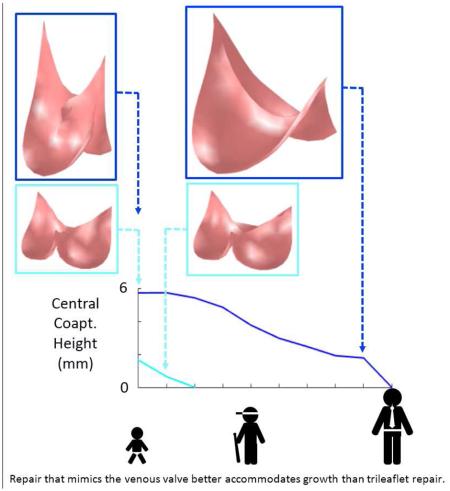
Neither heart valve repair methods nor current prostheses can accommodate patient growth. Normal aortic and pulmonary valves have three leaflets, and the goal of valve repair and replacement is typically to restore normal three-leaflet morphology. However, mammalian venous valves have bileaflet morphology and open and close effectively over a wide range of vessel sizes. We propose that they might serve as a model for pediatric heart valve reconstruction and replacement valve design. We explore this concept using computer simulation.
Methods
We use a finite element method to simulate the ability of a reconstructed cardiac semilunar valve to close competently in a growing vessel, comparing a three-leaflet design with a two-leaflet design that mimics a venous valve. Three venous valve designs were simulated to begin to explore the parameter space.
Results
Simulations show that for an initial vessel diameter of 12 mm, the venous valve design remains competent as the vessel grows to 20 mm (67 %), while the normal semilunar design remains competent only to 13 mm (8 %). Simulations also suggested that systolic function, estimated as effective orifice area, was not detrimentally affected by the venous valve design, with all three venous valve designs exhibiting greater effective orifice area than the semilunar valve design at a given level of vessel growth.
Conclusions
Morphologic features of the venous valve design make it well-suited for competent closure over a wide range of vessel sizes, suggesting its use as a model for semilunar valve reconstruction in the growing child.
Graphical abstract
1 Introduction
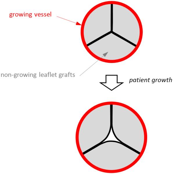
In congenital heart disease, the aortic and pulmonary valves are often affected. When valve disease is moderate to severe, surgery is required to prevent adverse cardiac remodeling that can ultimately progress to heart failure. In children, surgical repair of the valve is usually preferred over valve replacement (Baird 2009, Jonas 2010). In some cases, it is possible to preserve the native vessel and to reconstruct only the leaflets using pericardium or other tissues as grafts. However, the presence of non-growing leaflet grafts within a growing native vessel ultimately leads to regurgitation, stenosis, or both (Fig. 1).
Fig. 1.
Top image shows the cross section of a reconstructed semilunar valve in the closed position, with preserved (growing) vessel shown in red and leaflet grafts (non-growing) shown in gray. Bottom image illustrates that as the vessel grows, the non-growing leaflet grafts are pulled apart as the vessel (to which the leaflets are attached) moves radially outward with growth.
In cases where valve repair is not possible, the valve must be replaced. In neonates and small children, an aortic or pulmonary valve can be replaced by a homograft from a child donor of appropriate size, although demand for such small homografts greatly exceeds supply (Sinha 2009). Another approach is to use an adult-sized homograft that has been downsized by removing one third of the conduit including one leaflet (Michler 1994, Perri 2015). Valved femoral vein homografts have also been used and are available in appropriately small sizes (Sinha 2010), as are decellularized valved bovine jugular veins (Hasan 2011). In all of these cases, the implanted conduit and valve do not become living host tissues, but rather begin to degenerate and limit growth in the patient.
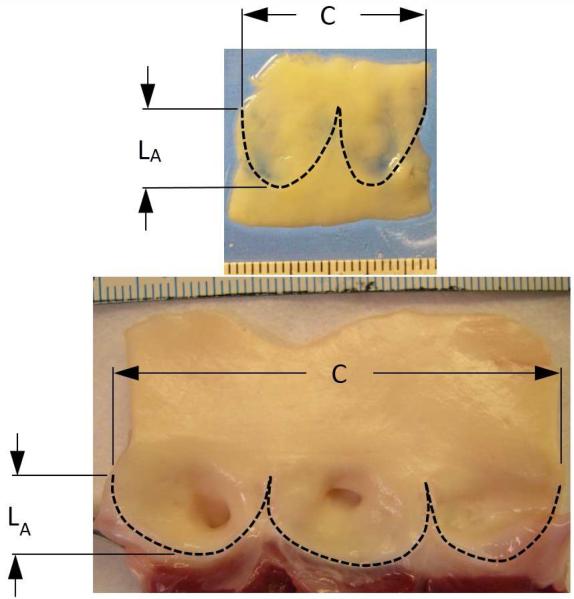
Venous valves, present in the lower extremities of humans and other large mammals, are usually bileaflet in structure, and their proportions are much different than those of cardiac semilunar valves. In the normal semilunar valve, the axial length of the valve is approximately half the vessel diameter, whereas in the venous valve, the axial length of the valve is considerably greater than the vessel diameter (Fig. 2). Furthermore, in contrast to the semilunar valves, the free edge of a venous valve leaflet is considerably longer than the vessel diameter. These shape differences might allow the closed valve to be more robust to vessel diameter changes. In fact, a venous valve is known to exhibit competent closure across a wide range of local venous pressure and vessel size caused by short-term stresses like postural changes and exercise. We hypothesize that based on geometric factors alone, a venous-like valve design can close over a wider range of vessel diameters than a semilunar-like valve design. When the reconstruction of a cardiac semilunar valve entails suturing non-growing leaflet grafts into a preserved outflow tract of a growing child, a reconstruction that mimics the bileaflet venous valve might be more resistant to regurgitation as the patient grows, thus delaying the need for reintervention.
Fig. 2.
Segments of a human femoral vein (top) and porcine aortic valve (bottom) from which the valve leaflets have been excised. Dimension C indicates the circumference of the vessel at the top of the leaflet attachment, and dimension LA indicates the length of the leaflet attachment in the axial direction of the vessel. Scales in both photographs indicate mm. In the venous valve, the axial length of the valve is considerably greater than the vessel diameter (1.3 times) whereas in the aortic valve, the axial length of the valve is approximately equal to half the vessel diameter.
To test this hypothesis, we use computer simulation. We have previously used computer simulation to study how different techniques for aortic valve surgical reconstruction affect the robustness of valve closure immediately following surgery (Hammer 2012, Hammer 2015). For these studies, the primary advantage of simulation was that it allowed a single dimension or feature of valve reconstruction to be varied while keeping all others constant. In this work, we extend our methods to simulate closure of a reconstructed valve in response to somatic growth, specifically isolating the effect of a venous valve (VV) versus a semilunar valve (SV) design on the reconstructed valve performance over a range of valve diameters. In this report, we describe our method for simulating the closed, loaded state of a reconstructed aortic/pulmonary valve and for predicting its competence in response to various degrees of somatic growth. We use the simulated closed states to assess valve competence and to compute measures of inter-leaflet coaptation. We also compute the effective orifice area of the open valve to estimate outflow resistance during systole.
2 Methods
In this section, we describe the methods used to simulate the closed, loaded state of both a venous valve design and a normal semilunar valve design. The geometry of the two valve designs is described as is the mechanical properties of the tissues used for valve reconstruction. We then describe how we simulate valve function in the presence of somatic growth and how diastolic and systolic function of the valve is quantified.
2.1 Finite element model of non-growing leaflet grafts in a growing vessel
In order to compare the amount of growth tolerated by bileaflet, venous-like valves with that of a typical trileaflet, semilunar-like valve, we use a structural finite element model of valve leaflet grafts attached to the walls of a cylindrical vessel of varying diameter. To predict the ability of a reconstructed valve to close without regurgitation during growth, we simulate the closed state of the valve in diastole, the phase of the cardiac cycle when the semilunar valves are pressurized and most likely to leak. Furthermore, while we are interested in the behavior of reconstruction of both aortic and pulmonary valves, we use valve shape data from aortic valves to define the geometry of the trileaflet, semilunar-like valve, and for both valve morphologies we simulate diastolic loading of the valves using values of systemic (arterial) pressure corresponding to the simulated age of the growing child.
2.1.1 Valve geometry
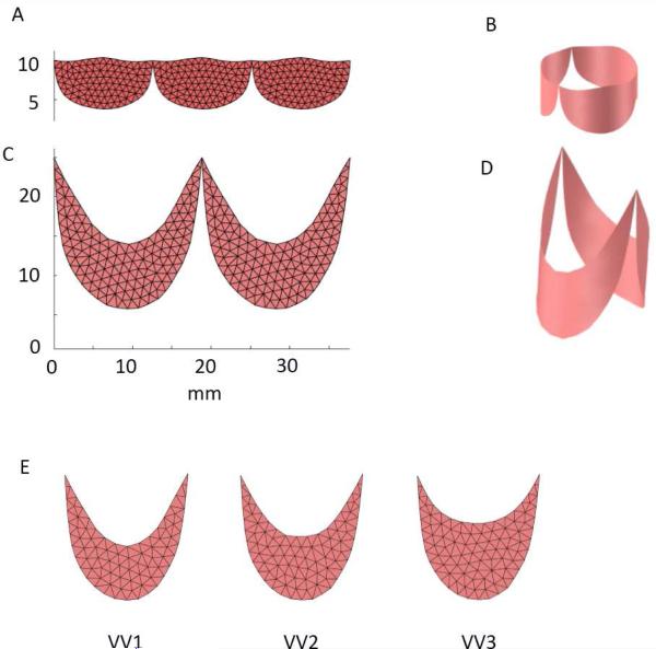
To create a model of semilunar valve (SV) design, we scale the average leaflet shape determined from studies of 18 porcine hearts (Hammer 2014) to the appropriate size for a child with an aortic root of 12 mm diameter. For the shape of the bileaflet, venous valve (VV) design, we take measurements from a single human femoral vein and again scale the resulting leaflet shape to a 12 mm diameter root. The planar leaflet outlines for both designs are meshed with triangles, replicated, and joined at their endpoints (Fig. 3, A and C). The planar meshes are wrapped into cylinders (Fig. 3, B and D) based on anatomical studies showing that the points of attachment of the leaflets to the aortic root lie on a cylinder (Swanson and Clark, 1974) and to our own experimental observations in both semilunar and venous valves. Approximately 300 triangles are used to represent the valve leaflet surface in each modeled valve morphology. To begin to explore the parameter space of the VV design, we run simulations using two additional leaflet shapes. Our planar, excised human femoral vein specimen exhibits a ratio of leaflet midline height to circumferential leaflet width of approximately 40% (design VV1). We also construct and simulate valves with this ratio equal to 50% (VV2) and 60% (VV3) (Fig. 3E).
Fig. 3.
(A) Planar outlines of the leaflets from a semilunar valve (SV) design was meshed with triangles and replicated. (B) Planar leaflet mesh was then wrapped into a cylinder with diameter of 12 mm. (C) Planar outlines of the leaflets from a venous valve (VV) design was meshed with triangles and replicated. (D) Planar leaflet mesh was then wrapped into a cylinder with diameter of 12 mm. (E) Three different VV leaflet designs were tested: VV1 with a midline height to overall height ratio of approximately 0.4 (based on our human femoral vein valve specimen), VV2 with height ratio of 0.5, and VV3 with height ratio of 0.6.
2.1.2 Leaflet mechanical properties
The finite element method that we apply uses knowledge of the relationship between stress and strain in a material to simulate deformation of the structures in response to applied loads. Heart valve leaflets and materials typically used for valve reconstruction undergo relatively large deformations under physiological loads, and this requires a description of the material mechanical properties appropriate for finite deformation theory. Accordingly, we describe leaflet mechanical properties using an exponential strain energy function of the form:
where W is strain energy density, c is a constant and
The values of A are constants, and E11, E22, & E12 are the normal and shear components of the Green strain tensor. Components of the second Piola-Kirchhoff stress tensor are computed as the partial derivatives of W with respect to the respective components of the Green strain tensor. The values of parameters c and A were chosen not to explicitly describe either venous valve leaflets of aortic or pulmonary valve leaflets, but rather to approximate general distensible tissue suitable for valve reconstruction (c = 50 kPa, A1 = 4, A2 = 4, A3 = 0, A4 = 4). The leaflets are modeled as a mesh of triangular membrane elements with constant thickness of 0.5 mm.
2.1.2 Simulating the pressurized valve in the growing root
We simulate the state of the valve under diastolic pressure in two steps. First the vessel, modeled implicitly as an elastic cylinder serving as the boundary to which the leaflets attach, is dilated to reach a target level of patient growth. The meshes representing the leaflet grafts do not grow and in fact may constrain the vessel during growth. In order to achieve a dilated state of the mesh boundary points that is consistent with the physical problem, we apply circumferential and axial forces to the boundary points representing stresses in the dilated vessel for a given diameter and pressure, and we also apply nodal forces due to stresses in the leaflets in elements that have an edge on the cylindrical boundary (Hammer 2015). From this condition representing the pressurized aortic root, the locations of mesh boundary points are held constant while surface normal forces representing transleaflet diastolic pressure are applied to close and load the leaflets. The closed state of the valve at normal peak pressure is computed by solving for the equilibrium position of the leaflets using the equations of motion (Newton’s Second Law) where forces act on the vertices of mesh triangles due to transleaflet pressure, leaflet deformation, inertial forces, and interleaflet contact. To estimate the forces due to leaflet deformation, we used a finite element approach developed for materials that undergo large deformations (Taylor 2005). The equations of motion are discretized using a second-order backward difference method and are solved using semi-implicit numerical integration with adaptive step size control. Simulation and analysis software was written in the Matlab programming language (Mathworks, Natick, MA, USA). The structural finite element analysis method that we have developed and applied was validated in previous work using simulated biaxial loading of square patches of leaflet tissue (Hammer 2011) and using ex vivo experiments of pressurized isolated aortic valves (Hammer 2012). See our previous work for details of the simulation methods (Hammer 2015).
2.2 Simulating growth
In the growing child, the diameter of the aortic root increases from approximately 10 mm in the neonate to more than 20 mm in the young adult (Sluysmans 2005). We first simulate closure of a valve within a root whose diameter in diastole is 12 mm representing a pediatric patient of approximately 2 years of age. Leaflet size is chosen so that leaflets are in the unstressed state when incorporated into the 12 mm diameter vessel. The closed state of the valve is simulated for the 12 mm diameter vessel size and also at 1 mm increments in vessel size until the leaflets fail to meet in the valve center. Only the leaflet boundary, representing the preserved growing vessel, changes in size between simulations, while the leaflet mesh, representing the non-growing leaflet grafts, remains a fixed size.
2.3 Quantifying valve closure
The robustness of closure of the valve is quantified by the amount of overlap of the leaflets in the valve center under peak load. Surgeons have noted that in the center of the valve, the amount of overlap, referred as central coaptation height, for a normal aortic valve is 3 to 5 mm and that successful aortic valve reconstruction is dependent upon a large central coaptation height (Augoustides 2010). From simulations of the pressurized valve, we computed the region of interleaflet contact, calculating both its area and the axial height of this region in the valve center.
2.4 Quantifying valve opening
The extent to which the simulated valve opens completely during systole was approximated by applying a 3 mmHg pressure difference across each leaflet element in the direction that opens the valve. The effective valve orifice area was then computed as the area of the open valve projected onto a plane perpendicular to the valve axis. Normalized area was then calculated as the effective valve orifice area divided by the cross sectional area of the vessel.
3 Results
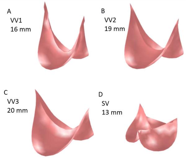
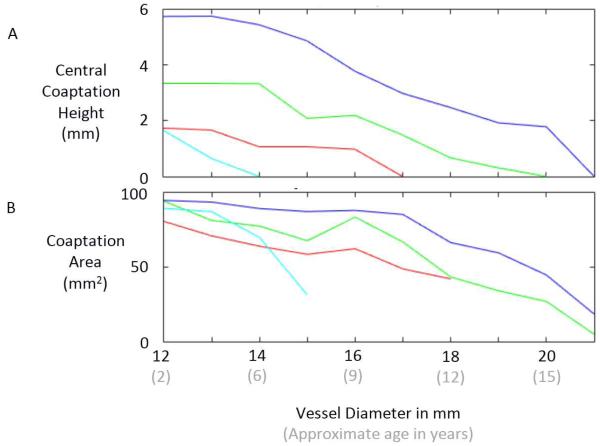
Inspection of the simulated closed state of the reconstructed valve shows that the VV design based on the human femoral valve shape (VV1) maintains competent closure during vessel growth up to a maximum vessel diameter of 16 mm (Fig. 4A). The VV designs with progressively greater leaflet midline dimensions (VV2 and VV3) maintain competent closure up to maximum vessel diameters of 19 and 20 mm, respectively (Fig. 4B-C). On the other hand, the SV design maintains competent closure only to a vessel diameter of 13 mm (Fig. 4D). Under diastolic pressure load, design VV1 is competent (central coaptation height > 0) as the vessel grows from the initial vessel diameter of 12 mm to a diameter of 16 mm (Fig. 5A). With further increases in vessel diameter, central coaptation vanishes and the leaflets open in the valve center, corresponding to central regurgitation of blood. Designs VV2 and VV3, with progressively greater leaflet midline dimensions, maintain central leaflet coaptation to vessel diameters of 19 and 20 mm, respectively (Fig. 5A). The SV design is less robust to vessel growth, maintaining central leaflet coaptation to a vessel diameter of only 13 mm. A similar trend is seen in the area of leaflet coaptation, with coaptation area of the SV design leaflet falling much more sharply than that of the VV designs as vessel diameter grows beyond 14 mm (Fig. 5B).
Fig. 4.
Results of simulations showing the loaded state of the reconstructed valve following the maximum vessel growth under which the valve remained competent. (A) VV1 design at vessel diameter of 16 mm. (B) VV2 design at vessel diameter of 19 mm. (C) VV3 design at vessel diameter of 20 mm. (D) SV design at vessel diameter of 13 mm.
Fig. 5.
Results of simulations showing central coaptation height (A) and coaptation area (B) versus vessel diameter for four different valve reconstruction designs: SV1 (light blue), VV1 (red), VV2 (green), and VV3 (dark blue).
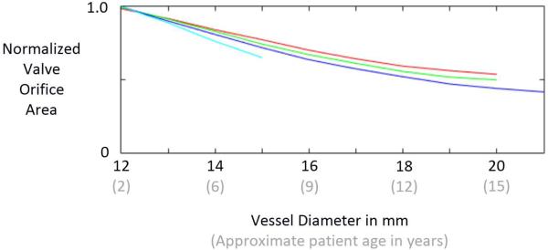
Results of our simplified estimate of valve opening show that all 4 valve designs exhibit a normalized effective orifice area of approximately 1.0 at the initial size of the vessel (12 mm), indicating that the valves open completely (Fig. 6). Normalized area decreases with increasing vessel diameter for all 4 designs. The VV1 design exhibits the slowest rate of area decrease with vessel diameter, followed by VV2, VV3, and SV. Area data could not be computed for the SV design at vessel diameters beyond 15 mm because it was not possible for the simulated vessel diameter to grow beyond that point due to the constraint imposed by the non-growing leaflets.
Fig. 6.
Results of simulations that estimate the ability of the reconstructed valve to open during systole as the patient/vessel grows. Normalized effective orifice area is computed by dividing the projected area of the open valve by the vessel cross-sectional area. The curves represent the semilunar valve (SV) design (light blue) and the three venous valve (VV) designs: VV1 (red), VV2, (green), and VV3 (dark blue).
4 Discussion
The goal of this simulation study was to compare the capacities of two different valve morphologies, a semilunar valve shape and a venous valve shape, to accommodate vessel growth in the absence of leaflet growth in pediatric patients. Results suggest that there are inherent, geometric features of the venous valve design, with its bileaflet morphology and relatively tall leaflet attachments, that allow it to close over a wider range of vessel sizes than the normal semilunar valve design. One salient feature that differentiates the two morphologies is the length of the free edge of the leaflet. This free edge length imposes a theoretical limit to how large a vessel the leaflet can accommodate because the free edge must extend from the vessel wall to the valve center and back during diastole for complete closure. Thus it is impossible for a leaflet whose free edge is less than twice the vessel radius to close completely. In the normal semilunar valve, the leaflet free edge is only slightly longer than twice the radius of the valve root in diastole, whereas in the venous valve design, the leaflet free edge is more than four times the vessel radius in diastole, allowing it to span the distance to the valve center at much greater vessel sizes. A second salient feature of the venous valve design is the bileaflet morphology. For a bileaflet valve, there are two interleaflet commissures, approximately 180 degrees apart, that are pulled in opposite directions as the vessel grows. As a consequence, the midpoint of a leaflet free edge moves axially upward along the valve center in response to vessel growth. For a trileaflet valve, there are three interleaflet commissures, spaced approximately 120 degrees apart around the vessel wall. In this case, as vessel growth moves the commissures radially outward from the vessel axis, the midpoint of a leaflet free edge is pulled both axially upward and radially outward. The combined effect of these two features of the venous valve morphology can be seen in our simulation results, with the best case venous valve design (VV3) remaining competent through 8 mm (67 %) of vessel growth while the semilunar valve (SV) design remained competent through only 1 mm (8 %). This result could have important clinical implications and suggests that a valve reconstructed with semilunar morphology in a 2 year old will begin to exhibit central regurgitation somewhere between the ages of 4 and 6, while with a venous valve morphology, the valve could remain competent until age 15 or 16 (Fig. 5).
In current surgical practice, three-leaflet semilunar valves are usually reconstructed in a way that maintains normal semilunar valve morphology. However there is precedent for exploiting the venous valve properties in cardiac surgery. Our group has implanted stented bovine jugular vein grafts (Melody valve) in the mitral position in infants and children and showed that the valve can subsequently be expanded via balloon catheter as the child grows while maintaining competence (Quinonez 2014). It is worth noting, however, that the Melody valve is a three-leaflet venous valve, and it is not known whether it can accommodate the same degree of growth as the bileaflet venous valve design.
An important variable that we did not explore is the relative stretch between the vessel and the leaflet graft at the time of implantation. Our simulations assume that the attachment of leaflet graft is unstretched when the diastolic diameter of the vessel is 12 mm. To achieve this, the surgeon incorporates redundancy into the graft using a running suture that progresses more (i.e., larger bites) on the graft than on the vessel wall (Hosseinpour 2013, Ozaki 2014). It is possible that further increases in this redundancy can produce even greater growth accommodation than in the simulations presented here.
Simulation results indicate that with increasing venous valve leaflet graft height, the amount of growth that the reconstructed valve can accommodate increases, and for a given vessel size, taller grafts lead to better coaptation metrics. However, tall grafts raise some concerns. First, as the height of the grafts that we simulated increases, the length of the free edge decreases. We surmised that valves with shorter leaflet free edges would become obstructive (small effective orifice area) at earlier stages of vessel growth. This trend can be seen in our results (Fig. 6), but it is difficult to know if this difference would be clinically significant. It is also interesting to note that even the tallest venous valve design (VV3) is associated with a greater effective orifice area than the semilunar valve design (SV) at a given vessel diameter. A second concern with tall leaflet grafts (e.g., design VV3), specifically for aortic valve reconstruction, is that if a leaflet does not close during diastole, it could obstruct flow into the coronary ostia. Further study is needed to understand the effects of these valve design factors.
The data from this simulation can be used either to guide techniques for valve repair or to design a prosthesis for valve replacement in children. Guided by simulations, an expandable prosthesis can be designed consisting of a bileaflet valve within an expandable stent with relatively high posts. The results of this simulation are consistent with experimental results from an expandable prosthetic valve utilizing human femoral vein grafts (Roberts 2015). Importantly, most repair techniques for aortic and pulmonary reconstruction recapitulate semilunar design, which may not retain competence as the surrounding vessel grows. A bileaflet design with tall leaflet attachments may be better repair strategy given the findings of this study.
Many simplifications were made in this simulation-based study. We simulated a single, generalized graft tissue with isotropic mechanical properties, yet the range of properties of potential graft tissues varies widely – due to both biological variability and to variable treatment protocols for decellularizing and stabilizing the graft tissues (Sacks 1998), (Meuris 2016). We also made no attempt to simulate the complex effects of systolic blood flow on leaflet stresses. Furthermore, we neglected to consider biological effects, such as fibrosis, calcification, and retraction, which are known to affect the long-term durability of implanted graft tissues. Another limitation of our study is the relatively large size of mesh elements (~1 mm) with respect to the output measure of central coaptation height of the valve. This relatively coarse mesh was chosen for computational speed and stability but at the expense of resolution. Smaller mesh elements, particularly near the center of the closed valve, would allow finer resolution of the onset of incompetence with increasing root diameter.
While the results of this simulation study are promising, more work is necessary before this valve reconstruction approach can be brought to the clinic. Our results showed that a venous-like valve reconstruction in a semilunar position has the potential to accommodate patient growth, but we did not thoroughly explore the design space across a wide range of leaflet shapes and material properties in order to propose an “optimal” design, although such a simulation-based optimization seems feasible. Beyond simulation, carefully designed experiments in explanted tissues will be necessary to compare performance of the reconstruction strategies will real graft materials and under realistic flow conditions, both for pulmonary and systemic positions, and in vivo animal procedures will be necessary to predict the biological responses to the proposed valve reconstruction strategy following years of implantation in the growing child.
Supplementary Material
Video legend. In the supplemental video, we briefly state the motivation for the study and describe the simulation methods. Two example simulations are shown – one for a reconstruction mimicking a normal semilunar valve and one for a reconstruction mimicking a venous valve – and results of the simulation study are summarized.
Central Message.
In computer simulation, venous-like valves close over a wide range of vessel sizes. Aortic or pulmonary valve reconstruction that mimics the venous valve might accommodate growth in the child.
Perspective Statement.
Aortic and pulmonary valve disease in the child usually requires multiple interventions, as current treatments cannot accommodate patient growth. We recently reported a stented venous valve in the pulmonary position that can be balloon dilated as the child grows. Here we use simulation to compare 2- vs 3-leaflet valve performance during growth. Results suggest that valve repair mimic the venous valve.
Acknowledgments
Disclosures and Freedom of Investigation
This study was supported by grant R01 HL110997 from the National Institutes of Health. All authors had full control of the design of the study, methods used, outcome parameters and results, analysis of data, and production of the written report.
Glossary of abbreviations
- VV
venous valve
- SV
semilunar valve
Footnotes
Publisher's Disclaimer: This is a PDF file of an unedited manuscript that has been accepted for publication. As a service to our customers we are providing this early version of the manuscript. The manuscript will undergo copyediting, typesetting, and review of the resulting proof before it is published in its final citable form. Please note that during the production process errors may be discovered which could affect the content, and all legal disclaimers that apply to the journal pertain.
The authors have no conflicts of interest to disclose.
References
- Baird CW, del Nido PJ. Complex aortic valve disease in children. Oper Tech Thorac Cardiovasc Surg. 2009;14(3):253–263. [Google Scholar]
- Jonas RA. Aortic valve repair for congenital and balloon-induced aortic regurgitation. Pediatr Card Surg Annu. 2010;13:60–65. doi: 10.1053/j.pcsu.2010.01.001. [DOI] [PubMed] [Google Scholar]
- Sinha P, Moulick A, Jonas RA. Femoral vein homograft for neoaortic reconstruction in Norwood stage 1 operation. Ann Thorac Surg. 2009;87:1309–10. doi: 10.1016/j.athoracsur.2008.09.007. [DOI] [PubMed] [Google Scholar]
- Michler RE, Chen JM, Quaegebeur JM. Novel technique for extending the use of allografts in cardiac operations. Ann Thorac Surg. 1994;57:83–87. doi: 10.1016/0003-4975(94)90369-7. [DOI] [PubMed] [Google Scholar]
- Perri G, Polito A, Gandolfo F, Albanese SB, Carotti A. Outcome of standard and bicuspidalized cryopreserved homografts for primary right ventricular outflow tract reconstruction. J Heart Valve Dis. 2015;24(1):83–8. [PubMed] [Google Scholar]
- Sinha P, Talwar S, Moulick A, Jonas RA. Right ventricular outflow tract reconstruction using a valved femoral vein homograft. J Thorac Cardiovasc Surg. 2010;139(1):226–8. doi: 10.1016/j.jtcvs.2008.10.018. [DOI] [PubMed] [Google Scholar]
- Hasan BS, McElhinney DB, Brown DW, Cheatham JP, Vincent JA, Hellenbrand WE, Jones TK, Zahn EM, Lock JE. Short-term performance of the transcatheter Melody valve in high-pressure hemodynamic environments in the pulmonary and systemic circulations. Circulation. 2011;4(6):615–20. doi: 10.1161/CIRCINTERVENTIONS.111.963389. [DOI] [PubMed] [Google Scholar]
- Hammer PE, Chen PC, del Nido PJ, Howe RD. Computational model of aortic valve surgical repair using grafted pericardium. J Biomech. 2012;45(7):1199–1204. doi: 10.1016/j.jbiomech.2012.01.031. [DOI] [PMC free article] [PubMed] [Google Scholar]
- Hammer PE, Berra I, del Nido PJ. Surgical repair of congenital aortic regurgitation by aortic root reduction: a finite element study. J Biomech. 2015;48(14):3883–3889. doi: 10.1016/j.jbiomech.2015.09.030. [DOI] [PMC free article] [PubMed] [Google Scholar]
- Hammer PE, Pacak CA, Howe RD, del Nido PJ. Straightening of curved pattern of collagen fibers under load controls aortic valve shape. J Biomech. 2014;47(2):341–346. doi: 10.1016/j.jbiomech.2013.11.032. [DOI] [PMC free article] [PubMed] [Google Scholar]
- Swanson WM, Clark RE. Dimensions and geometric relationships of the human aortic valve as a function of pressure. Circ. Res. 1974;35:871–882. doi: 10.1161/01.res.35.6.871. [DOI] [PubMed] [Google Scholar]
- Taylor RL, Oñate E, Ubach P. Finite element analysis of membrane structures. In: Oñate E, Kröplin G, editors. Textile Composites and Inflatable Structures. The Netherlands; Springer: 2005. [Google Scholar]
- Hammer PE, Sacks MS, del Nido PJ, Howe RD. Mass-spring model for simulation of heart valve tissue mechanical behavior. Ann Biomed Eng. 2011;39(6):1668–1679. doi: 10.1007/s10439-011-0278-5. [DOI] [PMC free article] [PubMed] [Google Scholar]
- Augoustides JG, Szeto WY, Bavaria JE. Advances in aortic valve repair. J Cardiothorac Vasc Anesth. 2010;24:1016–1020. doi: 10.1053/j.jvca.2010.08.007. [DOI] [PubMed] [Google Scholar]
- Sluysmans T, Colan SD. Theoretical and empirical derivation of cardiovascular allometric relationships in children. J Appl Physiol. 2005;99:445–457. doi: 10.1152/japplphysiol.01144.2004. [DOI] [PubMed] [Google Scholar]
- Quinonez LG, Breitbart R, Tworetsky W, Lock JE, Marshall AC, Emani SM. Stented bovine jugular vein graft (Melody valve) for surgical mitral valve replacement in infants and children. J Thorac Cardiovasc Surg. 2014;148(4):1443–49. doi: 10.1016/j.jtcvs.2013.10.059. [DOI] [PubMed] [Google Scholar]
- Hosseinpour A-R, González-Calle A, Adsuar-Gómez A, Santos-deSoto J. A simple method of aortic valve reconstruction with fixed pericardium in children. Interact CardioVasc Thorac Surg. 2013;16:695–697. doi: 10.1093/icvts/ivs547. [DOI] [PMC free article] [PubMed] [Google Scholar]
- Ozaki S, Kawase I, Yamashita H, Uchida S, Nozawa Y, Takatoh M, Hagiwara S. A total of 404 cases of aortic valve reconstruction with glutaraldehyde-treated autologous pericardium. J Thoracic Cardiovasc Surg. 2014;147(1):301–306. doi: 10.1016/j.jtcvs.2012.11.012. [DOI] [PubMed] [Google Scholar]
- Roberts EG, Quinonez L, Piekarski B, Baird CW, Emani SM. Expandable valve for pediatric application constructed from human venous valved conduit within a stent. Ann Thorac Surg. 2015;100(6):2320–4. doi: 10.1016/j.athoracsur.2015.07.059. [DOI] [PubMed] [Google Scholar]
- Sacks MS, Chuong CJ. Orthotropic mechanical properties of chemically treated bovine pericardium. Ann Biomed Eng. 1998;26:892–902. doi: 10.1114/1.135. [DOI] [PubMed] [Google Scholar]
- Meuris B, Ozaki S, Neethling W, De Vleeschauwer S, Verbeken E, Rhodes D, Verbrugghe P, Strange G. Tri-leaflet aortic valve reconstruction with a decellularized pericardial patch in a sheep model. The Journal of Thoracic and Cardiovascular Surgery. 2016 doi: 10.1016/j.jtcvs.2016.05.024. doi: 10.1016/j.jtcvs.2016.05.024. [DOI] [PubMed] [Google Scholar]
Associated Data
This section collects any data citations, data availability statements, or supplementary materials included in this article.
Supplementary Materials
Video legend. In the supplemental video, we briefly state the motivation for the study and describe the simulation methods. Two example simulations are shown – one for a reconstruction mimicking a normal semilunar valve and one for a reconstruction mimicking a venous valve – and results of the simulation study are summarized.


