

Abstract
Repair of damaged skeletal muscle tissue is limited by the regenerative capacity of native tissue. Current clinical approaches are not optimal for treatment of large volumetric skeletal muscle loss. As an alternative, tissue engineering represents a promising approach for the functional restoration of damaged muscle tissue. A typical tissue engineering process involves the design and fabrication of a scaffold that closely mimics the native skeletal muscle extracellular matrix allowing for organization of cells into a physiologically relevant, 3D architecture. In particular, anisotropic materials, which mimic the morphology of the native skeletal muscle ECM, can be fabricated using various biocompatible materialsto guide cell alignment, elongation, proliferation and differentiation into myotubes. In this article, we first provide an overview of fundamental concepts associated with muscle tissue engineering and the current status of the muscle tissue engineering approaches. We then review recent advances in development of anisotropic scaffolds with micro- or nano-scale features and examine how scaffold topographical, mechanical, and biochemical cues correlate to observed cellular function and phenotype development. Finally, we highlight some recent developments in both the design and utility of anisotropic materials in skeletal muscle tissue engineering along with their potential impact on future research and clinical application.
Keywords: Muscle, tissue engineering, anisotropic materials, scaffolds, nanofibers, micropatterned substrates
Graphical Abstract
Muscle tissue engineering approaches are reviewed focusing on anisotropic matrices including micropatternered substrates, aligned microporous and aligned fibrous scaffolds. Challenges associated with engineering aligned matrices are highlighted and correlation of scaffold topographical, mechanical and biochemical cues to cellular function and myogenic phenotype development is discussed.

1. Introduction
Skeletal muscle assumes many critical roles in the human body, including control and movement of limbs, respiration, and protection of abdominal viscera.[1] While skeletal muscle tissues possess innate repair potential, muscle defects larger than a critical volume cannot heal in a manner initiated by normal physiological processes and require surgical intervention to prevent scar tissue formation and loss of function.[2] Volumetric muscle loss (VML), or mass loss of ≥20% for a particular muscle, may result from acute trauma such as those associated with battlefield injuries, tumor excision or muscle wasting diseases such as muscular dystrophy. Notably, muscle wasting diseases affect 561 million people worldwide and represents a significant societal and economic burden.[3, 4]
The current clinical standard for treatment of significant muscle damage is autograft of healthy muscle tissue. Yet there are significant limitations to surgical grafting including shortage of donor tissue, loss of function at the donor site, and donor site morbidity. In contrast, tissue engineering constructs are designed to meet the functional and aesthetic requirements of tissue regeneration within a muscle defect. Strategically, they are fabricated in vitro and implanted to restore tissue function in vivo.[5–7] The constructs can be engineered with custom architectures in accordance with specific structural demands. Tissue engineering constructs may incorporate a patients’ own cells to promote tissue regeneration and/or vascularization in vivo to augment post-implant survival. Moreover, use of mechanical, chemical and/or electrical stimuli and pre-conditioning with growth factors can facilitate construct maturation in vivo thereby promoting post-implantation survival. In short, the tissue engineering approach to treating VML has many potential advantages over conventional surgical therapy.
The primary component of a tissue engineering construct is a scaffold, which is a biomaterial-based, three-dimensional (3D) platform that promotes cell attachment, proliferation, and tissue formation. Scaffolds used to support skeletal muscle regeneration should accommodate and promote formation of densely packed, highly-aligned myofibers throughout a large tissue volume. Recent studies suggest that anisotropic materials may be preferred for developing muscle tissue engineering constructs as they present morphology and function more closely resembling the native tissue.[8] Micropatterned or nanopatterned, two-dimensional substrates have proven useful in elucidating the key factors that mediate myogenic differentiation in vitro and multilayers of patterned materials serve as anisotropic materials in tissue repair.[9, 10] Three-dimensional (3D) aligned porous scaffolds[8, 11–13], as well as micro- and nano-fibrous scaffolds[14–19] are popular constructs for muscle tissue engineering, where the anisotropic architectures promote myogenic differentiation and formation and alignment of myotubes. Without proper alignment of myofibers, it is impossible to impose effective force transmission and contractility for regeneration of functional muscle fibers.[20] Therefore it is critical that muscle tissue engineering scaffold architectures present cues to pre-align muscle cells and thereby facilitate early-stage myogenic differentiation toward cell fusion, and formation of long and thick myotubes.[21, 22]
In this review article, we first provide a brief overview of the structure and organization of native muscle tissue and the design criteria for developing muscle tissue engineering scaffolds. We then cover methods for fabrication of anisotropic scaffolds with micro- and nano-scale features and review recent advances in development of such scaffolds. We examine how scaffold topographical, mechanical, and biochemical cues correlate to observed cellular function and phenotype development and provide a comprehensive review on in vitro and in vivo studies of anisotropic materials for skeletal muscle tissue engineering. Furthermore, we discuss the mechanisms by which engineered directional cues modulate cellular response; understanding the response of myogenic cells to these topographical cues will improve the design and optimization of clinically relevant scaffolds for treatment of volumetric muscle loss. Finally, we highlight some insights into the design and utility of anisotropic materials to advance engineered skeletal muscles towards clinical use.
2. Skeletal muscle tissue engineering approaches
2.1 Structure and organization of skeletal muscle tissue
Muscle tissue can be classified as smooth muscle, cardiac muscle, and skeletal muscle.[23] Skeletal muscle tissue, accounting for 40–50% of total body weight, is responsible for gross movements, and comprises densely packed multinucleated muscle fibers (Fig. 1). Muscle regeneration begins with fusion of multiple myoblasts into multinucleated myotubes with diameters in the range of 20–100 μm. Myotubes further differentiate into myofibers, which are covered by a thin layer of connective tissue (endomysium) mostly comprised of laminin and type IV collagen.[24] Approximately 20–80 myofibers attach in parallel to form a fiber bundle covered by a layer of type I collagen-rich perimysium. Finally, the epimysial layer covers several fiber bundles to form muscle tissue. These three sheath layers constitute the extracellular matrix (ECM) composed of glycosaminoglycans (GAGs), proteoglycans and proteins.[24] Vascular inflow into muscle tissue takes place through arteries that are distributed along muscle fibers. Vessel branching occurs obliquely or perpendicularly to the main vessels thereby surrounding muscle fibers and allow for their perfusion. In terms of functionality, contraction of striated, skeletal muscle is attributed to contractile fibers or myofibrils. The basic unit of a myofibril is the sarcomere, composed of fibrous proteins including myosin and actin, that slide past each other during muscle contraction and relaxation.[24]
Figure 1.

Schematic illustration of anatomic structures and organization of skeletal muscle tissue.
2.2 General approaches to skeletal muscle tissue engineering
There are three main approaches associated with muscle regeneration using muscle tissue engineering constructs. The first involves the isolation of muscle progenitor cells from an autologous source, in vitro culture and expansion of the progenitor cells seeding into a 3D scaffold and the implantation of the cell-seeded scaffold in the defect site (Fig. 2).[25] The second is the delivery of autologous progenitor cells, without in vitro expansion, directly to the defect site via a scaffold.[26] The third is the implantation of a cell-free, 3D scaffold designed to release cytokines and/or growth factors to stimulate the endogenous healing cascade leading to tissue regeneration.[26]
Figure 2.

Schematic illustration of skeletal muscle tissue engineering using aligned nanofibrous scaffolds. Effective skeletal muscle tissue engineering requires success at multiple stages which may include progenitor cell isolation, cell proliferation, cell culture on scaffolds in vitro, application of dynamic mechanical stimulation via bioreactor, characterization of myogenic implant quality and ultimately implantation into the patient.
Skeletal muscle tissue contains bundles of highly oriented, densely-packed myofibers composed of multinucleated muscle cells. Without proper alignment of myofibers, muscle fibers cannot effectively transmit force and contract efficiently.[20] Therefore muscle tissue engineering scaffolds require a unidirectional structure to pre-align muscle cells, guide cell fusion, and promote the formation of long and thick myotubes.[21, 22] Importantly, the design of anisotropic muscle tissue engineering scaffolds has been informed by research utilizing two-dimensional, micropatterned substrates that study the effects of topography and matrix elasticity on myoblast alignment and differentiation in vitro.[18, 27, 28] Typical examples of anisotropic constructs for muscle tissue engineering include 3D porous aligned micro-tubular scaffolds as well as aligned micro- and nanofibrous scaffolds.[14, 21, 22]
2.3 Cell lineages for skeletal muscle tissue engineering
Progenitor cells utilized for skeletal muscle tissue engineering (Table 1) must have high proliferative capacity and can efficiently differentiate into skeletal muscle cells.[29–31] Satellite cells, which are committed myoblast progenitors, migrate to muscle injury sites and are critical to normal physiological processes associated with muscle regeneration. However, the population of satellite cells in native muscle is limited and they exhibit limited proliferative capacity in vitro. [32, 33] As an alternative to committed myogenic progenitor cells, multipotent mesenchymal stem cells (MSCs) have high proliferative potential and demonstrate capacity for myogenic differentiation.[34–37] However, the in vivo transformation rate of MSCs to myofibers is low (~5%) compared to satellite cells (~10%).[38, 39] Interestingly, this rate was found to increase when the two cell types were transplanted together likely due to trophic effects of MSCs resulting in paracrine interactions that promote satellite cell differentiation.[40, 41] Finally, pluripotent stem cells also represent a potential progenitor cell source when differentiated into myogenic progenitor cells (MPCs).[42, 43]
Table 1.
Cells commonly used in skeletal muscle tissue engineering
| Cell type | Species | Source | Reference |
|---|---|---|---|
| Satellite cells | Human | Brachioradialis muscle | [134] |
| Human | Masseter muscle | [31] | |
| Rat | Lattissumus dorsi muscle | [135] | |
| Rat | Flexor digitorum brevis muscle | [136] | |
| Rat | Tibialis anterior muscle | [137] | |
| Mouse | Extensor digitorum longus muscle | [138] | |
| Frog | Iliofibularis muscle | [139] | |
| Muscle interstitial cells | Human | Blood vessel in skeletal muscle | [140] |
| Mesenchymal stem cells | Human | Bone marrow | [36] |
| Rat | Bone marrow | [36] | |
| mdx mouse | Bone marrow | [29] | |
| Blood-derived stem cells | Mouse | Dorsal aorta | [141] |
| AC133+ cells | Human | Blood | [142] |
| Pericyte-derived cells | Human | Blood vessel in skeletal muscle | [143] |
| Mesoangioblast stem cells | C57Bl/10 mice | Aorta | [144] |
| Dog | Vessel | [145] | |
| Embryonic stem cells | Human | Embryo | [42] |
| Secondary murine cells | C2C12 | C3H mice | [30] |
Myogenic differentiation is a process strictly regulated by paired box (Pax) transcription factors and the myogenic regulatory factor (MRF) family.[44, 45] Myoblasts undergo irreversible cell cycle arrest followed by a sequential upregulation of MRF family gene expression resulting in myoblast fusion into myotubes and followed by further maturation into multinucleated myofibers.[46] Early myogenic differentiation in adults is initiated in myogenic progenitor cells through the expression of Pax3 and Pax7.[45] The first step in the MRF regulatory cascade is the expression of MyoD and Myf5 (myogenic factor 5), thereby triggering expression of MyoG (myogenin) and Myf6 (also MRF4). As intracellular MyoG and Myf6 increase, myoblasts undergo terminal differentiation as they fuse into myotubes.[47] Expression of myosin heavy chain, intermediate filaments desmin and vimentin as well as α-actinin and troponin I can be associated with myotubes and is often used to confirm myogenic differentiation of myoblasts on various biomaterials.
2.4 Scaffold biochemical and biophysical cues critical to myogenesis
In order to engineer muscle tissue that functions similarly to its native counterpart, tissue engineering scaffolds should, at a minimum, attempt to mimic native muscle tissue with respect to morphology, which can be achieved by presenting proper biophysical cues and biochemical cues. The interplay of such cues regulates the development and maturation of tissue-engineered muscle.[48–50] Scaffolds with anisotropic architecture present critical biophysical cues providing contact guidance that influences cell morphology and promotes myoblast alignment leading to the formation of high-density cell sheets that can then undergo fusion and continue differentiation into myotubes, and perhaps functional myofibers. Examples of topographic cues that influence cell morphology and organization include microscale topographical features presented by micropatterned substrates, aligned polymeric fibrous matrices mimicking native extracellular matrix proteins, and 3D scaffolds with anisotropic porosity within which myoblasts can organize into wide and long myotubes. In addition, scaffold stiffness should match that of native muscle tissue allowing for cell exposure to relevant mechanical forces thereby influencing cell fate.[51, 52] The overarching mechanism at play with respect to scaffold stiffness is that mechanotransduction occurs via intracellular signaling, influencing cellular responses such as proliferation, differentiation, and other metabolic activities.[53] A substrate substantially stiffer than native muscle ECM would alter the behavior and phenotype of myoblasts, ultimately preventing maturation and formation of striated myofibers.[54]
During normal, physiological processes associated with muscle development, electrical impulses from the central nervous system play a critical role in promoting maturation of myotubes.[55] Without the guidance of electrical impulses, muscle tissue development seizes at the primary myotube stage preventing myofiber formation.[56, 57] The incorporation of electrically conductive constituents to muscle tissue engineering constructs, as is targeted by many researchers in the development of aligned nanofibrous scaffolds, provides conductivity cues that often have a complimentary effect on biophysical and/or biochemical cues.[18, 58, 59]
Scaffold biochemical properties regulate cell adhesion and influence cell behavior via contact signaling in a manner that is critical to successful myogenic differentiation.[60] Myogenic differentiation is generally induced upon attaining confluence of myoblasts arranged in a highly aligned, organized manner. Therefore, scaffold biochemical cues should promote maximal adhesion and proliferation. In anisotropic scaffolds for skeletal muscle tissue engineering, biochemical cues may be intrinsic to the scaffold base material as is the case for natural polymers, that present biochemical cues via functional surface groups.[61] Otherwise, to mimic native ECM, anisotropic scaffold surface functionality can be tailored via physical or covalent adsorption of biological molecules such as heparin and/or fibronectin or via other modifications[18, 62] to promote cell-surface interactions via integrins and subsequent induction of intracellular signaling pathways.[63] Functional groups inherent to various polymers, such as chitosan, are also useful for conjugation of additional biochemical moieties.[64, 65] Biochemical cues are thus generally presented in conjunction with topographic cues.
3. Micropatterned substrates for myogenic differentiation
Micropatterned substrates have been utilized extensively to examine the effects of microscale topographical cues on promoting myoblast anisotropy by contact guidance. These microscale topographical cues or features include sinusoidal patterns of defined wavelength, grooves/channels, ridges, holes or posts that can influence myoblast adhesion, polarization, alignment, fusion and/or differentiation into myotubes. Many early studies utilizing micropatterned substrates sought to understand in vitro myogenesis. More recently, micropatterned substrates fabricated from biocompatible materials are utilized to build multi-layered cell-scaffold constructs. In addition, micropatterned substrates are utilized to produce scaffold-free high cell density sheets that can be stacked to yield tissue substitutes.
3.1 Fabrication of micropatterned substrates
Materials used to create micropatterned substrates include glass, PDMS, polyacrylamide, and various other polymers.[27, 66–69] Materials that do not inherently promote cell adhesion are modified with proteins or peptides to promote the adhesion.[68] Photolithography and soft lithography techniques are the primary methods used to micropattern substrates.[70] Photolithography utilizes a layer of a light sensitive material, photoresist, applied to a substrate by spincoating, which is subsequently exposed to UV or optical light through a patterned photomask. The photoresist becomes a soluble (positive photoresist) or insoluble (negative photoresist) material after exposure. The exposed photoresist is removed by applying a developer, resulting in a layer of patterned photoresist and then the material of interest is deposited onto the substrate. Finally, the patterned photoresist is removed including unwanted material resulting in a pattern of the material of interest on the substrate. Depending on the specific application, appropriate materials are utilized to obtain micro-patterned substrates.
Micropatterned substrates can also be fabricated by soft lithography where 1) a silicon master with a patterned relief structure is fabricated, 2) the master is used to prepare an elastomeric mold or stamp by casting polydimethylsiloxane (PDMS) against it (Fig. 3a) and 3) the mold is utilized to produce substrates of different sizes, shapes and materials.[71] The advantage of soft lithography over photolithography is fabrication of the master only with a patterned relief structure which can then be used to prepare numerous copies of elastomeric molds or stamps.[70] Thus, the clean-room environment is not required and the cost for the production is significantly reduced. For microcontact printing, the pattern demarcated by the mold or stamp can be used to deposit biomolecules in a specific pattern (Fig. 3b). The mold is immersed in a solution of desired material and then stamped on a substrate resulting in a pattern transfer to the substrate surface via conformal contact. In the case of micromolding, the PDMS master is used as a negative mold to cast hydrogel biomaterials directly onto a substrate (Fig. 3c). This is achieved by placing a master directly onto the substrate and then injecting a polymer into the spacing defined by the mold. Curing the polymer and removal of the mold leaves a patterned material on the substrate. Finally, microtransfer printing utilizes the PDMS master to transfer pre-cast hydrogels (polymer in figure) onto a substrate (Fig. 3d). In addition, the PDMS master mold itself can be utilized as a cell culture substrate when modified with cell-adhesion promoting proteins or peptides.
Figure 3.

Soft lithography microfabrication techniques to generate patterned scaffolds (cross-sectional view). The related methods include: (a) replica molding, (b) microcontact printing, (c) micromolding and (d) microtransfer printing. Reprinted with permission, Copyright © 2012 IOP Publishing.[71]
3.2 Effect of topographical cues on myogenesis
Precise control over the morphology and dimensions of ridges/grooves/channels within microscale, patterned substrates allows for investigation of cell response to changes in those variables. In the context of muscle tissue engineering, it is important to characterize myoblast response to conditions and cues that promote myogenic differentiation and understand mechanisms driving those responses. Lam et al demonstrated C2C12 culture on flat, laminin-coated PDMS versus laminin-coated, micropatterned PDMS substrates presenting a continuous wavy pattern (Fig. 4a–b).[68] Wave features of 3, 6 or 12 μm periodicity, corresponding to amplitudes of 400, 600 and 1700 nm, were compared in terms of cell attachment and alignment. After six days, a monolayer of aligned myotubes was observed on all micropatterned substrates with optimal alignment on 6 μm wave feature substrates (Fig. 4c–d,f) whereas cells remained randomly oriented when cultured on flat PDMS substrates (Fig. 4e,g).[72] Actin filaments comprising the cell cytoskeleton were aligned with the wave pattern and cell nuclei within myotubes were both peripherally located and aligned with waves. Both wave size, likely due to contact guidance, and cell plating density, played a significant role in cell response. The optimal density (25% confluence) was such that cell-cell proximity was enough to balance cell-cell interaction in support of survival and proliferation without overwhelming any influence of the substrate topographic features. Cells plated at a suboptimal, high density resulted in cell crowding and a random cell orientation.
Figure 4.

SEM imaging of myotubes on aligned micropatterned substrates. (a) SEM image of the micropatterned PDMS substrate with a continuous sinusoidal wave pattern (top view), scale bar: 50 μm. (b) SEM image of the micropatterned PDMS substrate (cross-sectional view), scale bar: 10 μm. (c) Myotubes cultured on the micropatterned substrate. Black arrow indicates longitudinal microfeature direction, scale bar: 40 μm. (d,f) Aligned cytoskeleton and nuclei of cells cultured on micropatterned substrates, scale bar: 100 μm. (e,g) Randomly oriented cytoskeleton and nuclei of cells cultured on flat PDMS substrate, scale bar: 100 μm. Reprinted with permission, Copyright © 2009, 2006 Elsevier Ltd. [68, 72]
Channels and grooves, representing material anisotropy, displayed within micropatterned substrates have also provided important information regarding the effect of contact guidance on myoblasts and myotube formation. Yamamoto et al cultured C2C12s in channels (6.7 μm deep, 5–120 μm wide) created in glass via UV lithography micropatterning followed by etching.[73] At the optimal channel width of 20 μm, 85% of cells aligned and fused into myotubes as compared to control, flat substrates where only 4% of myotubes were aligned. They also observed nuclear clustering and elongation as well as alignment of thick actin filament bundles parallel to grooves over long distances. The staining intensity of the stress fibers appeared to vary regularly along the length of myotubes suggestive of a repetitive sarcomere-like pattern. Myoblast differentiation was additionally characterized by immunostaining for GLUT1, highly expressed in myoblasts with no expression in myotubes, as well as GLUT4, which is not expressed by myotubes, but rather by undifferentiated myoblasts. MyoD and Myf5, transcription factors associated with early stages of myogenesis, were highly expressed after one day in culture in microgrooves and then significantly decreased by day 6 indicative of the temporal expression pattern of MRF family transcription factors. Again, confining cells within microscale features of optimal dimensions promoted anisotropy of myoblast and myotube organization.
Topographical features that influence myoblast alignment are not limited to continuous patterns as evenly-spaced posts also promote myoblast alignment by providing contact guidance. Gringas and coworkers compared C2C12 monolayer culture on laminin-coated PDMS substrates that were flat, grooved (20 μm wide grooves separated by 20 μm) or displayed square posts (20 μm edge length separated by 20 μm).[74] Similar to other studies reporting myoblast culture on micropatterned arrays on grooves/channels,[66, 67, 69] C2C12s aligned within and parallel to grooves. Over time and under low serum conditions, aligned myoblasts fused and formed myotubes on all substrates with some key differences. Myotubes displayed a random versus aligned orientation on flat substrates and micropatterned substrates, respectively. Upon further experimentation with different substrates displaying varying topographies, height and spacing were determined as critical to myotube alignment. If groove widths or post spacing were too large, cells would respond as if the substrate was flat. If post heights were too large, cell-cell contact was inhibited thereby preventing myoblast fusion and myotube formation. If post height was too small, the cells would again respond as if the substrate was flat. Further, myoblasts aligned to square posts, but not circular posts. Talin, a cytoskeletal component of focal adhesions, was shown to localize differently to edges of square posts and to circular posts indicating a shape-dependence associated with cell alignment. Importantly, these researchers developed a geometrically-based model of myoblasts to elucidate cell behavior in response to variations in micropatterned features. Overall, they concluded that alignment behavior seemed dependent on maximizing cell contact area with respect to the substrate, which may be a critical factor to consider in the design of clinically relevant muscle tissue engineering constructs. This concept of maximizing cell contact area in support of myogenesis was also explored and confirmed by Sengupta et al.[75] In the case of human primary myoblasts cultured within this system, cell spreading area was the most potent predictor of differentiation potential leading to the longest, widest multinucleated myotubes that stained positively for α-actinin.
Micropatterned substrates can also be utilized to generate myotube multilayers in vitro. Zhao and co-workers cultured C2C12 cells in substrates containing microgrooves 2 μm wide and 7 μm deep. Cells settled into the grooves and displayed in-groove nuclear alignment. Additional cells were cultured on top of the original pre-aligned cells leading to differentiation and myotube formation. The cells in the upper layer differed in morphology from the base layer cells in that they were wider (40 μm wide myotubes) with less elongated nuclei. In addition, the cells in the upper layer differentiated more quickly than those in the base layer with more intense expression of myosin heavy chain as observed via immunostaining. The mechanisms associated with differentiation in the base layer compared with the upper layer are likely different in that the base layer cells were influenced by the periodic surface topography and lateral cell-cell interactions and signaling. Subsequent layers were influenced to differentiate by the periodic surface topology presented by base layer cells as well as paracrine signaling between layers.
3.3 Effect of substrate stiffness cues on myogenic differentiation
It is well known that mechanical properties of materials utilized for muscle tissue engineering can also have a significant influence on myogenic differentiation. Mesenchymal stem cell differentiation on collagen-coated polyacrylamide gels varied with gels of varying stiffness. Whereas MSCs adopted a neural lineage when cultured on soft gels and an osteoblastic lineage when cultured on stiff gels, an intermediate stiffness similar to that of muscle tissue (~1–10 kPa) resulted in myogenic differentiation.[76] This response to matrix elasticity is due to cell-generated forces that inform intracellular signaling or mechanotransduction. Recently, it has been shown that this correlation between MSC differentiation and stiffness of protein-coated matrices is due to matrix stiffness alone and not related to varying degrees of protein tethering that may be attributed to how matrices are prepared for cell culture.[77] Differentiation of MSCs into myoblasts represents the first step in muscle regeneration, but subsequent fusion of myoblasts and further differentiation into functional myotubes must be attained. Substrate stiffness cues also play an important role in formation of functional myotubes. Control over substrate stiffness can be achieved by changing variables such as the composition of multi-polymer composites, the molecular weights of polymer constituents, crosslinking agents and cross-linking times.[52] The effect of substrate stiffness can be examined using micropatterned soft gel substrates. Myotubes formed within micropatterned soft gel channels (Young’s modulus < 5 kPa) and stiff gel channels (Young’s modulus > 15 kPa) showed diffuse staining of actin and myosin heavy chain proteins, whereas gels with intermediate Young’s modulus of 8–11 kPa resulted in myotubes with distinctive skeletal muscle striations after 2 weeks (Fig. 5a,b).[54] Similarly, proper stiffness of aligned microgrooved scaffolds (~ 12 kPa) made of methacrylated gelatin resulted in formation of isotonic myotubes.[78] When C2C12 cells were cultured on collagen/polyacrylamide substrates of optimal stiffness and then a second cell layer cultured on top of the original layer, the upper cell layer demonstrated maximum myotube striation (Fig. 5c,d).[54]
Figure 5.

Fluorescent imaging of myotubes grown on aligned, patterned collagen gel substrates. (a) Fluorescent images of immunostained myotubes cultured for 2 weeks on micropatterned gel substrates of varying stiffness where intermediate stiffness resulted in myotubes with distinctive skeletal muscle striations (scale bar: 20 μm). (b) Immunostained images of myotubes after 4 weeks of culture on micropatterned gel substrates of varied stiffness (scale bar: 20 μm). (c) Myoblasts seeded in two sequential layers on patterned glass. After 1 week of culture, F-actin and myosin are becoming striated for upper layer myotubes, but are not striated for lower level myotubes (scale bar: 10 μm). (d) After 4 weeks in cultured, striated myotubes represent 85% of the myotube population in the upper layer whereas no myotubes are striated in the lower layer. Reprinted with permission, Copyright © 2004 The Rockefeller University Press [54].
3.4 Micropatterned substrates for generation of free-standing muscle constructs
More recently, micropatterned polymer substrates have been created for myoblast cell culture where the cell-substrate combination can be stacked to form multilayers. These multilayers are helpful to better understanding of the effects of vertical cell-cell interactions and may represent a bottom-up approach to tissue engineering if enough layers can be stacked to form a construct. Fujie and colleagues fabricated unique, standalone PLGA nanoribbon sheets by spincoating PLGA solution onto microgrooved (50 or 100 μm) PDMS and utilizing a sacrificial poly(vinyl alcohol) layer to release the nanoribbon sheet (Fig. 6a).[9] C2C12 cells aligned on nanoribbons and upon reaching ~80% confluence, an aligned cell sheet was coated with fibronectin and combined with a second PLGA nanoribbon/C2C12 sheet (Fig. 6e) to create a bilayer sheet with either an orthogonal (Fig. 6f) or parallel arrangement (Fig. 6g). Myotubes formed on single or bilayer aligned cell sheets were more aligned, significantly longer and more multinucleated than those on random bilayer cell sheets. The difference in myogenesis-related gene expression (myogenin, Mrf4, MHCIIa, MHCIId) was observed between single and bilayer aligned cell sheets, which was significantly upregulated in bilayers as compared with single layer culture. In addition, contraction of myotubes was visible for bilayer cell sheets without application of external electrical stimuli. Importantly, the difference in extent of myogenesis between single and bilayer cultures can likely be attributed to cell-cell interactions and the lower layer representing a biomimetic matrix in terms of mechanical properties and paracrine signaling.
Figure 6.
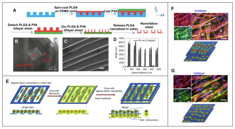
Microfabricated poly(lactic-co-glycolic acid) (PLGA) nanoribbon sheet for generation of hierarchically assembled mouse myoblast structure. (a) Schematic depiction of PLGA nanoribbon sheet microfabrication process. (b) Optical and (c) SEM micrograph (scale bar: 20 μm) depicting macro- and microstructure of nanoribbon sheet, and (d) graphical representation of nanoribbon height. (e) Schematic representation of cell bilayer sheet. (f) Immunostaining images of myotubes expressing myosin (green), F-actin (red) and nuclei (blue) on an anisotropic bilayer (A-bilayer, orthogonal) and an isotropic bilayer (I-bilayer, parallel) (scale bars: 100 μm). Reprinted with permission, Copyright © 2015 Elsevier Ltd.[9]
In some cases, monolayers of myoblasts or myotubes can be removed from micropatterned substrates for use as scaffold-free cell sheets that are stacked vertically to generate muscle tissues. Takahashi et al micropatterned hydrophilic poly(N-acryloylmorpholine) (PAcMo) onto thermoresponsive poly(N-isopropylacrylamide) (PIPAAm)-modified glass yielding 50 μm wide stripes.[10] Human skeletal myoblasts cultured on the substrates became aligned on the PAcMo micropatterns and myoblast monolayers released from the glass substrate by lowering the temperature. Interestingly, when a sheet of randomly oriented myoblasts was layered onto a sheet of aligned myoblasts, the cells on the randomly distributed sheet would reorient to align with cells in the adjacent layer. This occurred regardless of which layer was on top of the other and even if the two cell sheets were stacked perpendicularly. In the case of layering 5 sheets, a top anisotropic sheet dictated the cell orientation of all lower sheets even if the base sheet also contained aligned cells. Application of differentiation media to these cell sheets led to myotube formation. While the mechanisms that regulate alignment and self-organization are unknown, the authors demonstrated that cells can migrate vertically within multilayered sheets and N-cadherin binding and fibronectin-integrin interactions may play important roles in promoting self-organization.
Taken together, studies utilizing micropatterned substrates that present anisotropic topographic cues to myoblasts demonstrate that these cues influence myoblast behavior. When the dimensions of microscale topographic features are optimized, myoblasts can become highly aligned. The organized myoblasts subsequently fuse and differentiate into highly aligned, densely packed myotubes. The optimal dimensions of the substrate topography vary somewhat depending on the specific substrate material, but some studies indicate that differentiation in this context may be dependent on maximal cell spreading. The characterization of myoblast multilayers where the base layer is in contact with a substrate presenting topographical cues shows that subsequent layers benefit strongly from the pre-organization of the base layer. The mechanisms that drive differentiation of the base layer cells is likely different from myogenic differentiation in higher order layers due to enhanced cell-cell interactions and this may lead to clinically relevant scaffold-free tissues or tissue constructs formed via stacking of cell sheets. While likely not directly relevant to treatment of volumetric muscle loss, these systems are certainly useful for mechanism studies for tissue regeneration and may be useful for other applications or combined with space-filling scaffolds.
4. Aligned fibrous scaffolds for skeletal muscle tissue engineering
Fibrous materials have gained significant attention as base materials for tissue engineering constructs. Nanoscale fibers are notably relevant as they mimic the aspect ratio and size-scale of ECM proteins (e.g., collagen with 260–410 nm diameter)[79] and their high surface area-to-volume ratio promotes cell adhesion, migration, proliferation and differentiation. Nanofibers are produced from many natural and synthetic polymers, and importantly, aligned nanofibers facilitate alignment of myoblasts, representing a critical first step toward successful muscle tissue engineering. Nanofibers are commonly fabricated using one of three techniques: (1) electrospinning, (2) self-assembly and (3) phase separation.
4.1 Fabrication of aligned nanofibers by electrospinning
Electrospinning is widely utilized to produce nanofibrous materials due to its compatibility with various polymer systems and to its ability to produce stable, mechanically consistent nanofibers.[80, 81] Electrospinning involves feeding a polyelectrolyte solution through a metal or plastic needle connected to a high DC voltage source, resulting in the formation of a polymer solution jet that is directed toward a grounded collector (Fig. 7). The highly charged polymer jet stretches to many times its original length enroute to the collector and fibers form as the solvent evaporates. A wide variety of polymers, both natural and synthetic, can be electrospun to form nanofibers.[80, 82, 83] Table 2 lists some polymers that are typically used with electrospinning systems along with their associated properties. Electrospun nanofibers offer several advantages over nanofibers produced by other fabrication methods, such as control over fiber diameter and alignment, and the possibility of fabricating composite nanofibers.[80] One disadvantage of electrospinning is the limited control over the pore structure (spacing between fibers) of fibrous scaffolds, which often results in nanofiber mats that support low cell infiltration.[84]
Figure 7.

Schematic illustration of an electrospinning system used to produce aligned or randomly-oriented nanofibers. The system is comprised of a grounded collector, electrically charged spinneret and power supply.
Table 2.
Fabrication techniques to produce anisotropic nanofibrous scaffolds for skeletal muscle tissue engineering
| Method | Polymer(s) | Features | Reference |
|---|---|---|---|
| Electrospinning | Chitosan/polycaprolactone (PCL) | Easy fabrication, tunable mechanical properties and biological properties | [15] |
| Polyesterurethane | Compatible mechanical and biodegradable properties | [30] | |
| Collagen and gelatin | Relatively difficult fabrication, tunable mechanical properties and fiber diameter | [146] | |
| Polyaniline and poly(ε-caprolactone) (PCL) | Electrically conductive | [58] | |
| Polyurethane carbon nanotube | Electrical stimulation | [147] | |
| Poly (lactide-co-glycolide) (PLGA) | Elastomeric material, appropriate topology | [20] | |
| Poly(L-lactide) (PLLA) | Randomly oriented nanofibers were stretched to make them aligned | [91] | |
| PCL/collagen | Tunable mechanical properties | [14] | |
| Drawing | The polymers used for electrospinning | Single long nanofibers | [148] |
| Templating | The polymers used for electrospinning | Require different templates for different fiber diameters and fiber diameters range only 5–50 nm | [149] |
| Phase separation | Polymers that go through phase change when alteration to their physical environment occur | Limited types of polymers, slow and inconsistent, nanofibrous foam. | [150] |
| Self-assembly | Polymers with weak molecular interaction between the Molecules. Mainly protein-based polymers. | Complex process, small fiber diameter ~10 nm, very high porosity and water retention, limited mechanical strength. | [151] |
NB: Although self-assembly, phase-separation and templating techniques are used for nanofibers fabrication, they are not suitable for producing scaffolds with aligned nanofibers.
Most electrospinning systems produce fibrous mats with randomly-oriented nanofibers, but aligned nanofibers are desirable for myogenic tissue engineering applications. Several electrospinning systems with specially-designed collector configurations have been developed to produce aligned nanofibers (Table 3).[85, 86] Although they all produce aligned nanofibers, the degree or quality of fiber alignment and production rate vary among the different configurations. A multiplex electrospinning system was recently developed to produce aligned nanofibrous scaffolds of different shapes, including membranes, cylinders, tubes, arrays and crisscross patterns by utilizing different collector sets (Fig. 8).[87] Plate, pin, stepped cone and cylindrical collectors are used to produce aligned nanofibrous membranes, cylinders and tubular scaffolds, respectively (Table 3). A centrifugal electrospinning system (CES) that integrates the concept of parallel-collector electrospinning with centrifugal dispersion was developed to rapidly produce aligned nanofibers. With this system, a large-area nanofibrous mat with a high degree of fiber alignment and uniformity can be produced.[88] With multiple parallel-plate collectors arranged along the periphery of the system, a large number of aligned nanofiber mats can be deposited simultaneously.[89] The processes required to generate aligned nanofibers in this electrospinning system are well characterized and allow for the rapid production of nanofibrous materials with a number of tunable physical and mechanical properties.
Table 3.
Various collector configurations for fabrication of aligned nanofibers.
| Image or illustration of collector setup | Name of the collector, pros and cons | Reference |
|---|---|---|

|
Two-parallel-plate collector Pros: Simple setup, producing highly aligned fibers in membrane scaffolds, easy sample collection, fast fiber deposition. Cons: Decreased degree of alignment with increased gap width between the two plates; producing two-dimensional scaffolds only; the degree of fiber alignment decreases as the membrane thickness increases; a substrate is needed for collecting fibers. |
|

|
Static patterned collector Pros: Producing highly aligned fibers, fast fiber deposition, large area of fiber deposition. Cons: Expensive to setup, producing two-dimensional aligned fibrous membranes only, less aligned fibers with increased deposition, a substrate needed for collecting fibers. |
[152] |
|
Rotating two-pin collector Pros: Simple setup, producing highly aligned fibers in cylindrical scaffolds, producing three-dimensional scaffolds, producing stand-alone scaffolds, long aligned fibers. Cons: Less aligned fibers with increased deposition, small areas of aligned fibers, slow fiber deposition, slow fiber deposition with increased gap width between the two electrodes. |
[16] |

|
Rotating drum collector Pros: fast and large-area deposition of nanofibers. Cons: producing less aligned fibers, required for synchronized rotating speed and fiber deposition rate. |
[153] |

|
Rotating disc Collector Pros: simple setup, producing highly aligned long fibers. Cons: Slow and small-area fiber deposition, producing less aligned fibers as more fibers deposited, fiber continuity dependent on the disc rotating speed. |
[154] |

|
Rotating tube with knife-edge collector Pros: producing highly aligned fibers in tubular scaffolds, producing thick aligned fibrous scaffolds, stand-alone fibrous scaffolds. Cons: slightly complicated setup, aligned fibers only in the area above the knifes, knifes needed to be connected to negative terminal of power source. |
[155] |

|
Rotating wire-drum collector Pros: large-area, fast fiber deposition, producing highly aligned fibers. Cons: slightly complicated setup, producing two-dimensional fibrous membranes only, fiber continuity dependent on the drum rotating speed. |
[156] |

|
Rotating two stepped-cone collector Pros: producing highly aligned fibers in tubular scaffolds, easy fiber collection, producing 3D standalone nanofibrous constructs. Cons: Slow fiber deposition, producing less aligned fibers with more fibers deposited. |
[87] |

|
Multiple collectors in a centrifugal system Pros: Mass production of aligned fibers, easy fiber collection, better fiber alignment than two-parallel-plate collector. Cons: producing less aligned fibers with increased gap width between plates, producing two-dimensional scaffolds only, producing less aligned fibers with increased fiber deposition, a substrate needed for collecting fibers. |
[88] |
Figure 8.

A multipurpose electrospinning system and its modular collector electrodes designed in our laboratory. (a) Photograph of the electrospinning system and (b) modular electrodes of different configurations: (I) plate, (II) pin, (III) stepped conical and (IV) cylindrical electrodes. Aligned nanofibrous (c) membrane (scale: 2 μm), (d) cylindrical, (e) tubular and (f) criss-cross strutures (scale: 1 μm). Partly reprinted with permission, Copyright © 2013 Royal Society of Chemistry [87].
4.2 Effect of nanofiber topographical cues on myogenesis
Topographic cues provided by the micropatterned substrates discussed above were presented in the form of channels, ridges, continuous wave-like patterns or posts either recessed into or protruding from a 2D surface. In the case of electrospun, anisotropic fibers, cells adhere to fibers and respond by elongating along the length of the fiber. Choi et al fabricated randomly oriented and aligned polycaprolactone/collagen nanofibers (275–335 nm diameter) by electrospinning where fiber orientation was controlled by varying the rotational speed of the stainless steel collection plate.[14] Primary human skeletal muscle cells cultured on the substrates with unidirectionally oriented nanofibers aligned along the length of nanofibers whereas cells cultured on randomly oriented nanofibers displayed a polygonal morphology. At ~70% confluence, the medium was changed to low serum, differentiation conditions and after seven days, myotubes formed on aligned and randomly oriented nanofiber substrates with expression of desmin, myosin heavy chain and sarcomeric actin as confirmed by immunofluorescent staining. Homogenous organization of myotubes was much more pronounced on aligned nanofibers and the length of those myotubes was nearly twice that of myotubes on randomly oriented nanofibers. The effect of nanofiber alignment on myoblast-substrate interactions and on cell phenotype was further investigated via immunostaining of focal adhesion sites and actin filaments.[14, 90] On smooth polyurethane (PU) films, cells and nuclei appeared spherical, focal adhesions located around the periphery of the cytoplasm, and actin filaments hardly aligned (Fig. 9a). Cells cultured on randomly oriented PU nanofibers were elongated, focal adhesions located near cell nuclei and actin filaments were oriented along the elongated cytoplasm (Fig. 9b). On aligned nanofibrous PU substrates, focal adhesions were dispersed uniformly throughout the cytoplasm and actin filaments highly oriented along the aligned nanofibers (Fig. 9c). Similar phenomena were observed in the expression level of the transient receptor potential cation channel-1 (TRPC-1), a stretch-activated cation channel (Fig. 9d–f).[90] This indicates the possibility that the stress induced by alignment on myoblasts may contribute to differentiation into myotubes and that differentiation may be dependent on Ca2+ signaling pathways.
Figure 9.

Fluorescent imaging of immunostained focal adhesion and transient receptor potential cation channels-1 (TRPC-1) expressed by myoblasts cultured on substrates of different morphologies including flat film, randomly oriented and aligned nanofibers. (a–c) Images of focal adhesions (red) and actin filaments (green) of myoblasts. (d–f) Images of actin filaments (red) and TRPC-1 (green) confirming stretch-activated cation channel upregulation in cells in presence of aligned nanofibers. Nuclei were stained with DAPI. Scale bars: 20 μm. Reprinted with permission, Copyright © 2008 Springer [90].
To avoid the inclusion of biological materials such as collagen, Cooper and colleagues demonstrated successful electrospinning of randomly oriented (~215 nm diameter) and aligned (~187 nm diameter) chitosan-polycaprolactone (CPCL) nanofibers taking advantage of the hydrophilicity and nonimmunogenicity of the naturally-derived polymer chitosan.[15] C2C12 cells adhered normally to both nanofiber matrices and control CPCL films. By day 7 after cell seeding, the number of cells on aligned nanofiber matrices was almost double the number found on randomly oriented nanofibers and CPCL films, indicating nanofiber morphology played a role on cell proliferation. Cells cultured on CPCL films displayed a polygonal morphology whereas those on nanofibers appeared to interact with individual fibers resulting in a bipolar morphology. After 5 days of culture in differentiation media, highly aligned, elongated myotubes expressing myosin heavy chain were observed on aligned nanofibers in contrast to the short, branching myotubes observed on CPCL films and randomly oriented nanofibers. Studies on aligned nanofibers fabricated from a variety of polymers and utilizing primary human satellite cells, murine C2C12 myoblasts, or rat L6 myoblasts showed that scaffolds with aligned nanofibers direct cellular orientation thereby promoting myogenesis. Specifically, nanofiber topography may direct cytoskeletal reorganization to orient cells along the axis of the fibers and promote elongation.[15, 30]
Aligned nanofibers of various compositions have been shown to promote the alignment of myoblasts and support fusion and differentiation of myoblasts into myotubes, but scaffolds for muscle tissue engineering must also promote and/or facilitate further maturation of myotubes, and electrical conductivity and/or contractility. Therefore, many studies have focused on combining other cues with the topographical cues provided by aligned nanofibrous substrates to expedite myotube formation, such as chemical modifications of nanofibers and the inclusion of electrically conductive components.
4.3 Effect of nanofiber biochemical cues on myogenesis
Nanofibrous scaffolds are an ideal platform for presentation of bioactive molecules to enhance cell attachment, proliferation and differentiation.[30, 91] In order to improve the overall biocompatibility of synthetic polymers such as polycaprolactone, the nanofibers electrospun from these polymers are often functionalized with ECM proteins.[14, 30] Coating of bioactive molecules such as ECM proteins can be achieved via physical adsorption or covalent immobilization. Nanofibers made of synthetic polymers may be surface-modified via plasma treatment or partial surface hydrolysis to improve protein adsorption/immobilization.[18, 62, 92, 93] Due to a high surface area-to-volume ratio, a nanofibrous surface can absorb as much as sixteen times more protein than a flat surface of the same projected area. Thus, when biomolecules are applied to a nanofibrous surface, the density is much higher than that of protein adsorbed to its flat surface counterpart; this increased protein density can alter cell behavior.[94, 95] C2C12 cells seeded on fibronectin-coated, randomly-oriented PLLA fiber mesh contained unorganized actin filaments whereas the actin filaments of C2C12 were organized preferentially along fibronectin-coated PLLA fibers of aligned fibrous meshes.[91] In the latter case, the highly organized myotubes were significantly longer than those on randomly oriented fibrous scaffolds.
The utilization of natural proteins has generated concerns about immunogenicity, which prompted researchers to seek alternative coating materials. Guex and colleagues deposited a ~12 nm thick oxygen functional hydrocarbon coating onto aligned or randomly oriented PCL microfibers (~3.3 μm) and nanofibers (~237 nm) by radio-frequency plasma processing.[62] The coating did not change the fiber structure, remained stable for months and promoted cell adhesion and differentiation. The myotube density and length were higher on plasma-coated, aligned fibers. Interestingly, in this study, aligned microscale fibers outperformed nanofibers in terms of myogenesis, but supports the argument that aligned fibers are superior in promoting myogenesis to the randomly-oriented fibers. Myoblast alignment, fusion and differentiation has been reported for C2C12 cultured on aligned fibers with diameters ranging from ~187 nm (chitosan-PCL)[15] to ~12 μm (DegraPolã)[30] suggesting fiber orientation, not fiber size, is the primary cue that elicits myoblast morphological change and organization on fibers in vitro.
An alternative surface modification method was reported by Ku et al, inspired by proteins involved in mussel adhesion.[18] The surface modification of PCL nanofiber matrices utilized polymerization of dopamine (PDA) as an alternative to non-covalent and covalent immobilization of bioactive molecules. Overall, myotube length, total myosin heavy chain-positive area on aligned PCL nanofibers (560 nm diameter) after C2C12 cell culture was significantly greater on PDA-modified fibers than unmodified fibers. Enhanced differentiation of muscle cells on PDA-modified PCL fibers may be related to increased binding of serum proteins from culture media as well as superior maintenance of native protein structure.
4.4 Effect of nanofiber electrical conductivity on myogenesis
Incorporation of electrically conductive materials into aligned nanofibers is an approach to improve myogenesis by combining topographical cues with electrical cues. Researchers hypothesize that the presence of conductive materials will enhance myogenic differentiation in vitro and electrically active fibers may also promote further myotube maturation into myofibers in vivo. A number of research labs have experimented with blending conductive polyanaline (PANi) into traditionally electrospun polymers such as PCL.[17, 58] Upon increasing the PANi concentration in the PCL/PANi blend from 0 to 3 mg/mL (200 mg/mL PCL), Ku et al observed an increase in polymer solution conductivity and a decrease in nanofiber diameter (230–760 nm).[17] C2C12 cultured on randomly-oriented and aligned (60% of fibers ±10° of the y-axis) PCL/PANi nanofibers revealed that myotube formation was significantly influenced by nanofiber alignment as well as PANi concentration. This was reflected by differences in fusion/maturation index, myotube length, myosin heavy chain (MHC) expression and gene expression levels for early and late markers of myogenesis including myogenin, troponin T and MHC. Similarly, Chen et al reported the electrospinning of PCL/PANi nanofibers containing up to 3 wt% of PANi resulted in high fiber alignment and the resultant the fibrous matrices retained their topography and electrical conductivity for weeks in a hydrated environment.[58] By comparing aligned and randomly oriented fibers with and without PANi, results from this work indicate a complimentary, if not synergistic, effect of combining topographical and electrical guidance cues in terms of supporting and promoting myotube differentiation and maturation compared to the situations when individual cues were present alone.
As an alternative to the conductive polymer, PANi, conductive poly(3,4-ethylenedioxythiphene) (PEDOT) nanoparticles were incorporated in various ratios into PCL during electrospinning to form aligned nanofibers.[59] An increase in the nanoparticle concentration resulted in an increase in the fibrous scaffold conductivity, but a decrease in nanofiber alignment which may be attributed to the overall change in solution conductivity leading to difficulties in electrospinning and/or repulsion among resultant nanofibers. Sonication of the electrospinning solution to disperse PEDOT nanoparticles resulted in better nanofiber alignment, but electrical conductivity decreased below a threshold value. Importantly, PEDOT PCL nanofibers were biocompatible and increased metabolic activity of rat primary muscle cells over time during in vitro culture, but the fiber alignment in this system requires improvement. Recently, Manchineela and colleagues reported the addition of melanin, a naturally occurring polymer pigment with conductive properties, to silk fibroin, which produced nanofibers with better fiber alignment than fibers produced with silk fibroin alone.[96] While these silk-melanin nanofibers do not achieve the degree of alignment seen in other systems discussed here, there is a dramatic difference in alignment between the two conditions, and a significant advantage of this system is the utilization of naturally-derived materials. Aligned silk fibroin-melanin (SM) nanofibers were conductive and induced enhanced myogenic differentiation of C2C12s as compared to silk fibroin (SF) nanofibers, SF films and SM films, indicative of the importance of both topographic and conductivity cues.
4.5 Free-standing, nanofiber-based tissue engineering constructs
Although nanofibrous substrates mimic the native ECM, these substrates remain essentially two-dimensional in most cases as electrospinning thick nanofibrous mats, especially those targeted at VML, can be challenging. Some free-standing nanofiber-based constructs have been reported. Jana et al fabricated aligned nanofibers from chitosan/polycaprolactone blend using an electrospinning system with a specially-designed two-plate fiber collector (Fig. 10a–c).[16] Murine myoblasts (C2C12) cultured on the aligned nanofibrous mat showed uniform alignment and adhesion along the nanofibers (Fig. 10d). Although the nanofiber mat had sufficient strength to withstand reciprocating force from cells, it is not suitable for filling volumetric defects. Therefore, a uniaxially aligned chitosan-PCL nanofibrous cylindrical scaffold of 1 mm diameter and 1 cm long was produced by electrospinning using a custom-made fiber collector (Fig. 10e–g). This cylindrical scaffold is advantageous because of the ease in handling, similar to other monolithic 3D solid scaffolds and significantly, functions as a standalone scaffold with nanofibrous properties. C2C12 cells formed highly aligned, myosin heavy chain-positive myotubes along scaffold walls (Figure 10h–i).
Figure 10.

Aligned nanofibrous membranes and aligned cylindrical nanofibrous scaffolds prepared for skeletal muscle tissue engineering. (a) Photograph of an aligned fibrous membrane deposited between two plate electrodes by electrospinning, scale bar: 2 cm. (b–c) SEM images of an aligned nanofibrous membrane at (b) low magnification (scale bar: 5 μm), and (c) high magnification (scale bar: 700 nm). (d) Fluorescent image of aligned skeletal muscle cells cultured on aligned nanofiber membranes and immunostained for actin (green) and myosin heavy chain (red), scale bar: 20 μm. (e) Photograph of an aligned nanofibrous cylindrical scaffold deposited between two pin electrodes by electrospinning, scale bar: 4 mm. (f) SEM image of the cylindrical scaffold, scale: 50 μm. (g) SEM image of aligned nanofibers in the cylindrical scaffold, scale bar: 700 nm, inset: macroscale image of a cylindrical scaffold, scale bar: 2 mm. (h) SEM image of aligned myotubes grown on the aligned nanofibrous cylinder, scale bar: 100 μm. (i) Fluorescent image of myotubes grown on the nanofibrous cylindrical scaffold immunostained for actin (green), myosin heavy chain (red) and nuclei (blue), scale bar: 20 μm. Partly reprinted with permission, Copyright © 2012 American Chemical Society [16].
Wang and co-workers combined polycaprolactone/silk fibroin/PANi nanofiber yarns (NFY) fabricated via a wet/dry electrospinning process with poly(ethylene glycol)-co-poly(glycerol sebacate) (PEGS-M) photocurable hydrogel to form a core (NFY) shell (PEGS-M) sheet scaffold (Fig. 11),[19] which is an alternative approach to producing nanofiber-based, free-standing scaffolds for skeletal muscle tissue engineering. The rationale behind this design is that nanofiber mats are essentially dense, 2D matrices cannot serve as standalone scaffolds for VML, and elongated pores in 3D porous scaffolds cannot easily accommodate uniform cell seeding leading to difficulty in forming dense and highly aligned myotubes. Here, NFYs 25–165 μm in diameter were composed of nanofibers of 600–900 nm in diameter, and the hydrogel shell with high water content serves to both protect the NFYs and cells and allow for proper nutrient exchange in support of myogenic differentiation. C2C12 cells formed aligned, MHC positive myotubes on the outer surface of nanofiber yarns.
Figure 11.

Core-shell scaffolds containing aligned nanofiber yarns. (a) Schematic depiction of core-shell column and sheet scaffolds by combining electrospun, aligned nanofiber yarns (NFYs) and hydrogen shell composed of photocurable poly(ethylene glycol)-co-poly(glycerol sebacate) (PEGS-M). (b) Fluorescence-based visualization of core-shell structure showing aligned, 100 μm diameter nanofiber yarn encapsulated by PEGS-M. (c) C2C12 adhesion and proliferation on aligned NFY within PEGS-M shell. Reprinted with permission, Copyright © 2015 American Chemical Society.[19]
5. Anisotropic, microporous scaffolds for myogenic differentiation
Various polymeric, microporous scaffolds have been investigated for skeletal muscle tissue engineering, but in most cases, the pores of scaffolds are randomly-distributed, leading to the formation of unaligned, isotropically distributed myotubes in vitro,[97–99] and therefore, myotubes grown in these scaffolds have limited potential to fuse into aligned myofibers. Alternatively, anisotropic microporous scaffolds, those with aligned pores or cell-laden struts – provide a microenvironment that is more amenable to the formation of aligned myotubes.
5.1 Fabrication of aligned microporous scaffolds
Three-dimensional, porous scaffolds are often fabricated via thermally-induced phase separation (TIPS) followed by lyophilization.[8, 13, 100, 101] TIPS is a popular fabrication method to generate porous scaffolds with random pore distribution, but can also be used to generate scaffolds with aligned pores (Fig. 12).[102] For example, to produce an aligned microporous scaffold, a thermally insulating cylindrical tube (e.g., Teflon) is filled with an aqueous polymeric solution and a temperature gradient in the freezing range of the solvent is established between the two ends. As the polymer solution freezes, the aqueous phase crystallizes into cylinders with microscale diameters and the polymer phase is deposited between the solvent crystals.[8] When lyophilized, the solvent crystals sublime resulting in a microscale, tubular polymer structure with aligned pores. The pore size, porosity and scaffold wall thickness depend mainly on the magnitude of temperature gradient and polymer concentration. This method is simple, inexpensive, easy to follow and suitable for large-scale production. The disadvantages of this method include lack of uniformity in shape and wall thickness for aligned tubular pores. In some cases, the tubular pores are not continuous over the entire length of the scaffold and the connectivity between pores may be limited.
Figure 12.

Schematic illustration of fabrication process for aligned microporous tubular chitosan scaffolds via TIPS. (a) Chitosan powder and its chemical structure which contains an -NH2 group. (b) Chitosan gel-solution prepared in an aqueous acid solution. (c) Cylindrical Teflon tube as mold filled with chitosan gel-solution. (d) Centrifugation of chitosan gel-solution to remove voids. (e) Application of a thermal gradient between two ends of the tube, resulting in freezing along the cylindrical axis. (f) Lyophilization of frozen chitosan gel-solution. (g) Resultant cylindrical chitosan scaffold with aligned longitudinal microporous structure (longitudinal view), scale bar: 100 μm. (h) Cross-section of aligned chitosan scaffold showing pore dimensions, scale bar: 100 μm. Reprinted with permission, Copyright © 2013 John Wiley & Sons, Inc. [8].
Conventional scaffold fabrication methods allow for some degree of control in scaffold pore size, geometry, interconnectivity, etc, but these can be imprecise. Thus, bioprinting is gaining popularity as a means to fabricate tissue engineering scaffolds with well-defined architectures. Bioprinting can be utilized for deposition of natural or synthetic matrix materials onto 2D substrates or for fabrication of 3D scaffolds in a layer-by-layer fashion, with or without cells. Often, imaging technologies such as computed tomography (CT) or magnetic resonance imaging (MRI), are coupled with computer-aided design (CAD) and printing technologies to produce 3D scaffolds, including inkjet bioprinting, microextrusion bioprinting or laser-assisted bioprinting.[103] Solid scaffolds with aligned pore structures can be fabricated from synthetic melt polymers such as polycaprolactone (PCL) and poly (lactic acid-co-glycolic acid) (PLGA) because of their high mechanical strength and and predictability, however these synthetic polymers are not favorable in supporting cell adhesion and often produce toxic degradation products.[104] Natural polymers have better biocompatibility, but their physical properties are generally inferior to synthetic polymers, making them difficult to print or extrude.[105]
5.2 Myogenesis within aligned microporous scaffolds
In contrast to micropatterned 2D substrates and aligned nanofibrous scaffolds, it can be difficult to decouple the effects of biophysical and biochemical cues on myogenesis within aligned microporous scaffolds because of a lack of control conditions. Whereas micropatterned 2D substrates are often compared with flat substrates and aligned nanofibrous scaffolds compared with randomly oriented nanofibrous scaffolds, there is no completely appropriate or rational control for 3D, microporous scaffolds. Here we review some important aligned microporous scaffolds, but note that there are far fewer examples of these constructs than microporous scaffolds with random pore orientation, micropatterned substrates and aligned fibrous scaffolds.
Successful formation of an aligned myotube that can subsequently fuse with other myotubes to form myofibers requires pre-alignment of myoblasts. Therefore, microporous scaffolds with an internal architecture capable of guiding myoblast alignment are advantageous in facilitating the formation of aligned myotubes. Kroehne et al reported the fabrication of collagen sponge scaffolds with aligned microscale pores by inducing unidirectional freezing followed by freeze-drying.[13] Pores, 20–50 μm in diameter, are interconnected by collagen fiber strands (Fig. 13d). A high density of C2C12 cells was seeded onto dry scaffolds (6 mm × 3 mm × 2.5 mm), allowed to attach and proliferate for up to seven days before changing to low serum fusion media. Differentiated, aligned myotubes formed within scaffold pores as evidenced by sarcomeric myosin (myosin heavy chain) expression and deposition of laminin (Fig. 13b,c). Myotube formation within collagen scaffolds was likely due to synergistic effects between biochemical cues presented by collagen to promote cell adhesion and proliferation and biophysical topographic cues presented as aligned pore structure promoting long range organization of a dense layer of myoblasts. After 30-day culture, C2C12 colonized scaffolds were transplanted into the bed of excised anterior tibial muscle of transgenic eGFP mice (Fig. 13, lower panel). The scaffold was sutured to tissue under the knee and the distal tendon. Myotubes present within scaffolds matured in vivo, underwent some fusion with host cells and contributed to regeneration of muscle tissue that did not occur in empty and cell-free scaffold controls.
Figure 13.

Collagen-based aligned pore scaffolds for skeletal muscle tissue engineering. (a) H&E staining showing collagen (pink) and myotubes (purple) after 7 days of culture to induce myogenic differentiation. Myotubes express myosin heavy chain (b) and synthesized and deposited laminin (c) (scale bar: 100 μm, inset scale bar: 10 μm). (d) SEM micrograph of collagen scaffold microstructure (scale bar: 100 μm). Lower panel: C2C12-collagen scaffold graft after 2 week implantation in anterior tibial muscle of eGFP transgenic mouse (g: graft, h: host, k: knee, arrow: regenerated tendon) (scale bar: 200 μm). Reprinted with permission, Copyright © 2008 Blackwell Publishing Ltd.[13]
A hybrid technology involving a natural protein material, robotically-controlled dispensing technology, TIPS and microgroove topographical cues was utilized to fabricate 3D, porous collagen scaffolds containing aligned, concave microgrooves (120–380 μm diameter) wider than collagen pores described above. Depending on the microgroove diameter and cell-seeding density, the construct promoted formation of highly-aligned muscle bundles from rat L6 skeletal myoblasts in vitro resulting in thick, more clinically-relevant cell sheets.[11] The concave nature of the microgrooves promoted myotube alignment whereas the width of microgrooves (380 μm) likely contributed to the formation of multi-layers thereby promoting cell-cell interactions and resulting in muscle bundles with significant nuclear alignment and highly organized F-actin. While it is evident collagen scaffolds support myofiber formation in vitro and in vivo, one drawback of collagen is its instability in vivo due to a fast degradation rate and low mechanical strength. This can result in wound contraction and poor integration with host tissue.[106, 107] Therefore, the utilization of non-protein, naturally-derived polymers as scaffold base materials may be preferable. Jana et al utilized TIPS techniques to modulate the pore size, orientation and mechanical properties of chitosan scaffolds by varying polymer concentration (4, 6, 8 or 12 wt%) and freezing temperature (−20°C, −70°C, −180°C) and temperature gradient (Fig. 14).[8] As temperature gradient or polymer concentration increased, the pore size decreased where pores of all scaffolds, except for 12 wt% scaffolds, were well-aligned longitudinally. Importantly, the compressive moduli of most of the hydrated scaffolds fell within the 40–125 kPa range, comparable to native muscle tissue. Culture of myoblasts within the aligned pores of 6 wt% (~150 μm pore diameter) and 8wt% (~110 μm pore diameter) chitosan scaffolds prepared using a medium-temperature gradient resulted in cell alignment and subsequent differentiation into myotubes with physiologically relevant diameter (~50 μm) and length (~500 μm). In this scaffold system, chitosan provided appropriate biochemical cues to promote cell adhesion and proliferation whereas the aligned pores provided biophysical cues directing cell elongation and maturation. Importantly, the diameter of resultant myotubes was greater on stiffer 8wt% scaffolds than less stiff 6wt% scaffolds indicating a role of scaffold stiffness on myogenesis and a synergistic effect of multiple engineered cues on promoting myogenic differentiation within scaffolds.
Figure 14.

Chitosan scaffolds with unidirectional microtubular pores. (a–d) SEM micrographs depicting cross-sectional pore structure and arrangement of 4, 6, 8 and 12 wt% chitosan scaffolds prepared under a medium temperature (MT) gradient during TIPS processing (scale bar: 40 μm). (e–h) SEM micrographs of myotubes formed along the longitudinal direction of microtubular pores formed under the MT-gradient where scaffold is colored green for easier identification of myotubes (scale bar: 60 μm). (i–l) Immunoflurescent staining of C2C12-derived myotubes formed on 8 wt% scaffolds prepared under the MT-gradient, depicting cell nuclei, actin and myosin heavy chain expression after 2 weeks of culture (scale bar: 50 μm). Reprinted with permission, Copyright © 2013 John Wiley & Sons, Inc.[8]
3D bioprinting may represent a technological advance that will provide the control necessary to fabricate complex, freeform, clinically relevant tissue engineering constructs that will realize the seemingly elusive goal of regenerating tissues in humans using biomaterial scaffolds. Bioprinting can be utilized to impart material anisotropy on different length scales possibly allowing for the combination of various biophysical and biochemical cues in a controlled manner. Topographical cues may be conferred on multiple length scales as one can imagine the possibility of encapsulating cells and aligned nanofibers within a hydrogel scaffold strut, which is itself a unidirectional structure. Kang and colleagues recently demonstrated the utility of their integrated tissue-organ printer (ITOP) in fabrication of stable, freeform tissue constructs for multiple hard and soft tissue applications including skeletal muscle tissue engineering.[12] The ITOP system utilizes clinical imaging data to define defect shape and dimensions and a multidispensing system to print scaffolds composed of cell-laden hydrogel (combination of gelatin, fibrinogen, hyaluronic acid, glycerol, DMEM media). For purposes of skeletal muscle tissue engineering, a 15 mm × 5 mm × 1 mm construct was mainly composed of C2C12 cell-laden hydrogel deposited as muscle fiber-like bundles (~400 μm wide) along with PCL support structures and sacrificial Pluronic F-127 hydrogel (Fig. 15a,b). Confining the cells within unidirectional hydrogel bundles/rods spanning PCL support pillars imparted contact guidance and after 3 days in growth media, cells were elongated along the longitudinal axis of bundles (Fig. 15c). Interplay of cell contractility and surrounding matrix mechanics results in hydrogel compaction meaning that hydrogel bundles remained taut thereby maintaining structural anisotropy. After 7 days in differentiation media, aligned, myosin heavy chain-positive myotubes formed (Fig. 15d). The nature of the scaffold base hydrogel material, including multiple naturally-derived components, imparted undefined, but likely critical, biochemical cues promoting cell viability, organization and proliferation and differentiation. Constructs were evaluated in vivo via subcutaneous implantation in rats where the common peroneal nerve was embedded in the construct (Fig. 15e). After two weeks, myotubes within constructs had matured into muscle fiber structures and importantly, nerve integration had been initiated. Muscle fibers expressed myosin heavy chain, desmin, and acetylcholine receptor (AchR) clusters as evidenced by α-BTX binding/expression (Fig. 15f–h). Also present among tissue engineered muscle fibers were neurofilaments and von Willebrand factor positive endothelial lumen structures (Fig. 15i).
Figure 15.

Skeletal muscle tissue engineering scaffold fabricated using an integrated tissue-organ printer (ITOP). (a) Schematic depiction of construct designed to mimic array of aligned muscle fiber bundles including PCL support pillars (green). (b) 3D printed scaffold before (left) and after (right) removing sacrificial Pluronic F-127 hydrogel. (c) Live/dead staining of cells within hydrogel bundles shows high cell viability immediately after printing. (d) Immunofluorescent staining for myosin heavy chain shows myoblast alignment along the fiber after 7 days of culture. (e) Subcutaneous placement of construct in mouse with dissected common peroneal nerve inserted into construct to promote nerve integration. (f) After 2 weeks of implantation, cells within the construct organized into muscle fiber structures as evidenced by desmin staining and (g) expression of myosin heavy chain and α-BTX. (h) Evidence of nerve integration via doublestaining for α-BTX and neurofilament (NF). (i) Constructs became vascularized as evidenced by expression of von Willebrand factor. Reprinted with permission, Copyright © 2016 Nature Publishing Group.[12]
6. Mechanisms of cellular responses to anisotropic materials
When cells come in contact with scaffolds, they are influenced by multiple factors including material composition and associated biochemical cues, topographical features (microscale and nanoscale), spatial organization of micro- and nano-topography as well as mechanical properties such as scaffold stiffness/elasticity.[108] We have reviewed the utilization of anisotropic materials/materials presenting engineered directionality for skeletal muscle tissue engineering with a focus on topographical cues that influence myoblast spreading/elongation, alignment and subsequent myogenic differentiation. Studies highlighted above indicate our ability to induce myogenic differentiation in vitro on a variety of biomaterials and to incorporate cues that improve differentiation, which represents significant progress in the field. Although substantial research has been performed to characterize the response of skeletal myoblasts to engineered directionality, the mechanisms underlying cellular behavior in response to topographical cues remain to be clarified.[109–112] Creating awareness of and understanding mechanisms underlying the effect of aligned materials on myogenesis is critical to improving our collective approach to skeletal muscle tissue engineering. Furthermore, understanding the mechanisms driving myogenesis within in vitro platforms will allow for design and development of scaffolds that can recruit host cells or initiate endogenous tissue regeneration cascades in situ, which may prove to be a superior approach to the delivery of cells via scaffolds. Few studies have been carried out to examine, in detail, mechanisms specifically associated with myoblast response to engineered directionality, but conclusions drawn from studies of myoblasts and other cell types cultured on anisotropic materials can provide some clues as to how anisotropy affects myoblasts.
Engineered directionality in substrates and scaffolds utilized to study myogenesis and skeletal muscle regeneration imparts contact guidance on cells due to the inherent sensitivity of cells to topographic cues on multiple length scales. Contact guidance is mediated, at least in part, via adhesion signaling and cytoskeletal organization.[113] Integrins, transmembrane proteins critical for cell adhesion, are ~10 nm wide, prevalent on cell surfaces, and play a role in facilitating contact guidance.[114] Integrins allow cells to bind and respond to their extracellular environment by creating a link between the intracellular cytoskeleton and extracellular matrix proteins or a scaffold surface. Recently, McClure et al provided some evidence that α7β1 integrin signaling may play a role in mediating myogenic differentiation in response to fiber alignment.[45] Focal adhesions represent a more mature and complex connection between cytoskeletal elements and the ECM. Focal adhesions are large, dynamic protein complexes that mediate intracellular cytoskeletal dynamics and facilitate changes in intracellular signaling in response to the ECM.[115] [116] Studies involving micropatterned substrates and C2C12 culture described above concluded that maximizing cell-substrate contact area appears critical to promoting myogenesis[74, 75] and this may relate to maximizing integrin signaling and focal adhesion formation. Nain and co-workers observed, via time-lapse microscopy, C2C12 cell migration on aligned fibrous scaffolds.[117] Cells attached to the scaffolds by forming multiple focal contact points on the fibers. While undergoing prophase through anaphase of the cell cycle, cell migration continued along the direction of aligned fiber orientation. Daughter cells formed during cytokinesis spread out along two neighboring, but distinct fibers and elongated along the direction of the fiber orientation, resembling myotube morphology that subsequently fused into macroscale bundles.
Cell behaviors such as spreading, migration, growth and differentiation can be directly influenced by the environment surrounding the cells including the matrix or substrate topography and some critical cell responses can be attributed to the behaviors of lamellipodia and filopodia, which are actin-based, cellular protrusions that guide cell polarization and migration. Whereas lamellipodia are characterized as sheet-like protrusions located at the leading edge of a migrating cell, filopodia are thin, finger-like projections that extend beyond lamellipodia and constantly probe the surrounding environment via elongation and focal adhesion formation.[110, 118–120] Filopodia contain parallel bundles of filamentous F-actin which are essential for focal adhesion generation.[110] F-actin reorganizes associated focal adhesions structures to form focal-adhesion-anchored, tension-generating stress fibers.[121] Importantly, all three categories of anisotropic materials described above have been shown to promote the alignment and organization of F-actin and thus stress fibers.
Although it is often generalized that filopodia and lamellipodia work together through sensing and mechanical traction, You et al, using microgrooved or nanofiber-coated silk fibroin films, found that formation and advancement of lamellipodia were guided by activities of exploratory filopodia (Fig. 16).[109] Therefore filopodia play an important role in cell spreading and migration.[111] Filopodia have been shown to respond to variation in the diameter (hundreds of nm) of silica beads indicating the ability to identify differences in topographical features.[122] On micropatterned substrates, cells align along the pattern direction through periodic extension and retraction of lamellipodia parallel to the grooves/ridges (Figure 16 a–d).[109, 123] This is directly related to alignment of actin filaments and focal adhesions along substrate topographies demonstrating a link between anisotropic topographic features and cell behavior.[124] On aligned nanofiber-coated film substrates or nanopatterned substrates, cells protrusions were positioned along the direction of nanofibers or grooves through actin polymerization (Fig. 16 e–h) whereas cells on a substrate with nano-columns showed an increased number of filopodia, which guided cell migration via FAK and myosin II activity.[109, 125, 126] Focal adhesion kinase (FAK), is an important cytosolic protein component of focal adhesions because it mediates adhesive signaling by activating integrins and promoting integrin binding.[127, 128] On nanopatterned substrates, the extent of cell adhesion and spreading depends on the distance between nanoscale features, reflecting length scales associated with integrin clustering and focal adhesion signaling.[129, 130] Overall, cells on anisotropic materials, including aligned nanofibrous substrates appear to respond to biophysical topographic cues by forming aligned focal adhesions. In addition, traction forces are generated via the alignment of actin and formation of stress fibers. Aligned focal adhesions may be associated with filopodia that sense and recognize directional cues and thus guide cell polarity and migration in part by influencing the unidirectional spreading of lamellipodia.[113]
Figure 16.

SEM images of cells spreading on anisotropic substrates after 1, 2, and 4 h of culture. (a)–(d) Spreading of a cell on a micropatterned substrate with passage of time, the image in (b) is the magnified image of region indicated in image (a), inset image in (d) is the magnified image of region indicated in image (d). (e–h) Spreading of a cell on an aligned nanofiber-coated film substrate with passage of time, the image in (f) is magnified image of region indicated in image (e), arrow in image (h) shows the alignment of the cell along the nanofibers. The short and long arrows indicate filopodia and lamellipodia, respectively. Scale bars: (a) and (c) 5 μm; (b) 3 μm; (d) and (h) 50 μm; (e) and (g) 20 μm; (f) 10 μm and inset in (d) 5 μm. Reprinted with permission, Copyright © 2015 AVS Publication, Inc.[109]
In addition, some studies suggest that cell-cell interactions occur via filopodia in the formation of adherens junction [111] Filopodia also play an important role in cell-cell matching where they participate in orientating and matching cells prior to adhesion.[131, 132] The role of filopodia in cell-cell interactions between myoblasts and/or myotubes remains to be elucidated, but in the context of anisotropic materials, cell-cell interactions depend mainly on cell density, separation between features that provide directional cues, alignment and cell types.[112] If the cell density is high enough that filopodia may engage, cell-cell interaction may take place via filopodial projections. Expression of cytoskeleton regulators in cells cultured on aligned versus randomly oriented nanofibers was probed using a microarray. After applying a fold-change magnitude threshold (> 20%) and statistical significance threshold, eight of forty-eight genes associated with actin production, actin polymerization and focal adhesion formation were found to be significantly upregulated.[133] Taken together cell adhesion, spreading/elongation, alignment and migration in response to topographic cues displayed by anisotropic scaffolds are mediated by a complex interplay of factors including, but not limited to, focal adhesions, cytoskeletal elements, filopodia-mediated activities and traction forces. Generally speaking, it appears that design of scaffolds for skeletal muscle tissue engineering should feature topography that arranges cells to maximize cell-substrate contact and optimize cell organization to promote cell-cell interactions.
7. Conclusions and future prospects
Development of tissue engineered constructs for treatment of volumetric muscle loss is a significant healthcare priority. The three general approaches to scaffold-based tissue engineering of skeletal muscle to treat volumetric muscle loss are: 1) cell-free, 3D scaffold that activates resident muscle progenitor cells and associated endogenous healing cascades when implanted in vivo, 2) 3D scaffold seeded with autologous muscle progenitor cells and implanted in defect site without in vitro expansion, 3) 3D scaffold seeded with autologous muscle progenitor cells that have undergone in vitro expansion and/or pre-conditioning prior to implantation. There is no doubt that to achieve the first, cell-free approach, we must significantly further our understanding of the plethora of cues required to activate resident muscle precursor cells as well as our understanding of cell signaling pathways during myogenesis and endogenous healing cascades associated with muscle regeneration. At a fundamental level, all three tissue engineering approaches obviously require a biocompatible, porous, space-filling construct that presents proper biophysical and biochemical cues to promote the organization of high-density muscle precursor cells that can subsequently differentiate into myotubes and then myofibers. A large body of work exists in the development of muscle tissue engineering scaffolds encompassing various types of constructs. Significant progress has been made in our understanding of myogenesis in vivo and in vitro, but clinically relevant constructs are still lacking. This might be largely due to the inherent complexities associated with regenerating functional tissues and skeletal muscle also requires consideration of vascularization, innervation and contractility, where the latter two factors are associated with electrical impulses. Throughout this review, we sought to focus on the scaffold portion of skeletal muscle tissue engineering constructs and to understand how scaffold biophysical and biochemical cues can influence myogenesis.
Over the last decade, a general consensus seems to have been reached that anisotropic materials/constructs are critical for maximizing organization of muscle precursor cells in order to achieve skeletal muscle tissue engineering. Here we considered three main categories of anisotropic materials/scaffolds for myogenesis including 1) micropatterned substrates, 2) aligned fibrous scaffolds and 3) anisotropic microporous scaffolds. Response of myogenic cells to anisotropy presented by micropatterned substrates is generally alignment of nuclei and cytoskeletal elements leading to cell elongation, alignment, proliferation to a high density and subsequently enhanced myogenic differentiation compared with flat substrates. Optimal microscale feature dimensions vary somewhat depending on substrate material (e.g. PDMS, polyacrylamide or glass), but the anisotropic nature of micropatterned substrates provides contact guidance cues. Substrate stiffness cues in conjunction with topographical cues have been investigated using micropatterned soft gels indicating that matrix elasticity can be optimized to improve myogenic differentiation. Early work with micropatterned substrates focused on myoblast monolayer culture, but more recently, investigators have considered the effect of substrate topographical features on myoblast multilayer culture. These studies have shown that myoblasts, prealigned via contact with micropatterned substrates, themselves constitute a more biomimetic matrix for reorganization or enhanced myogenic differentiation of myoblasts seeded in subsequent layers above the base layer.
Aligned fibrous scaffolds are biomimetic for extracellular matrix structure in terms of high surface area and aspect ratio. Compared to randomly oriented nanofibers, aligned nanofibers promote elongation and alignment of myoblasts. Thus nanofiber topography directs cytoskeletal reorganization to orient cells longitudinally along the axis of the fiber. In addition, aligned nanofiber surface modification such as adsorption of proteins, plasma deposition of an oxygen functional hydrocarbon coating or polymerization of small molecules such as dopamine has further improved myogenic differentiation compared to unmodified nanofibers. This suggests a coordinated or perhaps synergistic effect between topographic and biochemical cues although the mechanisms associated with enhanced myogenesis remain to be elucidated. Incorporation of electrically conductive elements such as the conductive polymer polyaniline in conjunction with fiber alignment also improves extent of myotube differentiation and maturation.
To date, there are surprisingly few reports of microporous scaffolds displaying anisotropic topographical cues either in terms of scaffold pores, as is the case for collagen and chitosan scaffolds fabricated via TIPS, or scaffold struts as is the case for scaffolds fabricated via 3D bioprinting. In the latter case cell-laden hydrogels constitute scaffolds struts while mimicking muscle fiber bundles and imparting alignment cues. Porosity is defined by spacing between struts and allows for diffusion of nutrients into the relatively large constructs. It seems that none of the three classes of anisotropic materials represent an optimal skeletal muscle tissue engineering scaffold although scaffolds fabricated from hydrogels and stiffer polymers do hold great promise. More extensive in vivo studies are necessary to determine whether or not myotube maturation can exceed the primary stage reported in many in vitro works. Alternatively, hybrid scaffolds may prove useful for maximizing myogenic potential and importantly, serve as a cell-free construct that engages host myogenic precursors. As an example, a microscale scaffold with aligned, tubular pores and aligned nanofibers within the pores may be a feasible design. Similarly a scaffold with microscale architecture fabricated via bioprinting that is subsequently coated with aligned nanofibers is another alternative. A distinct challenge associated with nanofibers utilized on their own or as a component of a hybrid scaffold is the spacing between individual fibers. This spacing, sometimes referred to as porosity, is often small and limited thus hindering cell infiltration. To address this issue, one option is the formation of core-shell nanofibers with a sacrificial shell layer. Alternatively, complete removal of intermediate nanofibers interspersed among the base nanofiber material can be achieved by co-spinning followed by dissolution of the intermediate fibers. These types of constructs must be carefully designed because they require solvent systems with distinct characteristics for proper and controlled dissolution of select materials.
Beyond scaffold architecture and the importance of anisotropic materials for skeletal muscle tissue engineering, a brief mention of additional factors that may improve myogenesis in vitro is warranted. One important consideration with respect to skeletal muscle tissue is that native muscle tissue is consistently subject to cyclic stretching and contraction resulting in conversion of mechanical stimuli to electro-chemical activity. Therefore, appropriate mechanical stimulation of cells cultured on anisotropic scaffolds can promote myoblast survival and maturation. To achieve functional in vitro skeletal muscle tissue engineering, artificial electrical stimuli may be necessary to promote the transition of skeletal muscle cells to functional myofibers. In addition, electrical impulses act to coordinate the nervous system with the musculoskeletal system to facilitate muscle movement. Innervation of engineered muscle tissue is therefore critical to the formation of functional muscle and electrical stimulation may be an efficient way to induce innervation in vitro. Finally, vascularization and innervation of tissue engineered skeletal muscle are compelling challenges. The metabolic demand of muscle is high compared to other tissues and innervation is required to facilitate action potentials leading to muscle contraction. Therefore, approaches to facilitate neovascularization and innervation should be considered in the design of anisotropic scaffolds for skeletal muscle tissue engineering.
Great strides have been made in bettering our understanding of parameters influencing myogenic differentiation and the requirements of tissue engineering scaffolds to promote formation of highly-aligned, dense myofibers. Nonetheless, multiple, significant challenges remain in the pursuit of skeletal muscle tissue engineering and an exploration of studies associated with muscle tissue engineering scaffolds indicates the importance of pursuing anisotropic materials and constructs. Improving the design and applicability of currently available anisotropic materials/constructs requires extending our awareness and understanding of mechanisms underlying the influence of engineered directional cues on cell behavior. Additionally, it is necessary to explore how the combination of directional cues and other cues (stiffness, biochemical modifications and electrical conductivity) influence myogenesis and to recognize that engineered directionality on multiple size scales in the form of hybrid scaffolds may be important to making skeletal muscle tissue engineering clinically relevant.
Acknowledgments
This work was supported in part by NIH grant R01CA172455, Washington Research Foundation gift, and Kyocera Professorship Endowment (Professor Miqin Zhang). Sheeny K. Lan Levengood acknowledges support from the Ruth L. Kirschstein NIH training grant T32CA138312.
References
- 1.Tiidus PM. Skeletal muscle damage and repair. Human Kinetics; Champaign, IL: 2008. [Google Scholar]
- 2.Jarvinen TA, Jarvinen TL, Kaariainen M, Aarimaa V, Vaittinen S, Kalimo H, Jarvinen M. Best Pract Res Clin Rheumatol. 2007;21:317. doi: 10.1016/j.berh.2006.12.004. [DOI] [PubMed] [Google Scholar]
- 3.Grasman JM, Zayas MJ, Page RL, Pins GD. Acta Biomater. 2015;25:2. doi: 10.1016/j.actbio.2015.07.038. [DOI] [PMC free article] [PubMed] [Google Scholar]
- 4.Manring H, Abreu E, Brotto L, Weisleder N, Brotto M. Front Physiol. 2014;5:1. doi: 10.3389/fphys.2014.00037. [DOI] [PMC free article] [PubMed] [Google Scholar]
- 5.Kuraitis D, Giordano C, Ruel M, Musaro A, Suuronen EJ. Biomaterials. 2012;33:428. doi: 10.1016/j.biomaterials.2011.09.078. [DOI] [PubMed] [Google Scholar]
- 6.Lepper C, Partridge TA, Fan CM. Development. 2011;138:3639. doi: 10.1242/dev.067595. [DOI] [PMC free article] [PubMed] [Google Scholar]
- 7.Sato M, Ito A, Kawabe Y, Nagamori E, Kamihira M. J Biosci Bioeng. 2011;112:273. doi: 10.1016/j.jbiosc.2011.05.007. [DOI] [PubMed] [Google Scholar]
- 8.Jana S, Cooper A, Zhang M. Adv Healthc Mater. 2013;2:557. doi: 10.1002/adhm.201200177. [DOI] [PubMed] [Google Scholar]
- 9.Fujie T, Shi X, Ostrovidov S, Liang X, Nakajima K, Chen Y, Wu H, Khademhosseini A. Biomaterials. 2015;53:86. doi: 10.1016/j.biomaterials.2015.02.028. [DOI] [PubMed] [Google Scholar]
- 10.Takahashi H, Shimizu T, Nakayama M, Yamato M, Okano T. Biomaterials. 2013;34:7372. doi: 10.1016/j.biomaterials.2013.06.033. [DOI] [PubMed] [Google Scholar]
- 11.Chen S, Nakamoto T, Kawazoe N, Chen G. Biomaterials. 2015;73:23. doi: 10.1016/j.biomaterials.2015.09.010. [DOI] [PubMed] [Google Scholar]
- 12.Kang HW, Lee SJ, Ko IK, Kengla C, Yoo JJ, Atala A. Nat Biotechnol. 2016;34:312. doi: 10.1038/nbt.3413. [DOI] [PubMed] [Google Scholar]
- 13.Kroehne V, Heschel I, Schugner F, Lasrich D, Bartsch JW, Jockusch H. J Cell Mol Med. 2008:12. doi: 10.1111/j.1582-4934.2008.00238.x. [DOI] [PMC free article] [PubMed] [Google Scholar]
- 14.Choi JS, Lee SJ, Christ GJ, Atala A, Yoo JJ. Biomaterials. 2008;29:2899. doi: 10.1016/j.biomaterials.2008.03.031. [DOI] [PubMed] [Google Scholar]
- 15.Cooper A, Jana S, Bhattarai N, Zhang MQ. J Mater Chem. 2010;20:8904. [Google Scholar]
- 16.Jana S, Cooper A, Ohuchi F, Zhang MQ. Acs Applied Materials & Interfaces. 2012;4:4817. doi: 10.1021/am301803b. [DOI] [PubMed] [Google Scholar]
- 17.Ku SH, Lee SH, Park CN. Biomaterials. 2012;33:6098. doi: 10.1016/j.biomaterials.2012.05.018. [DOI] [PubMed] [Google Scholar]
- 18.Ku SH, Park CB. Advanced healthcare materials. 2013;2:1445. doi: 10.1002/adhm.201300067. [DOI] [PubMed] [Google Scholar]
- 19.Acerbi I, Cassereau L, Dean I, Shi Q, Au A, Park C, Chen YY, Liphardt J, Hwang ES, Weaver VM. Integrative biology : quantitative biosciences from nano to macro. 2015;7:1120. doi: 10.1039/c5ib00040h. [DOI] [PMC free article] [PubMed] [Google Scholar]
- 20.Aviss KJ, Gough JE, Downes S. European Cells and Materials. 2010;19:193. doi: 10.22203/ecm.v019a19. [DOI] [PubMed] [Google Scholar]
- 21.Bian WN, Bursac N. IEEE Eng Med Biol Mag. 2008;27:109. doi: 10.1109/MEMB.2008.928460. [DOI] [PMC free article] [PubMed] [Google Scholar]
- 22.Koning M, Harmsen MC, van Luyn MJA, Werker PMN. J Tissue Eng Regen Med. 2009;3:407. doi: 10.1002/term.190. [DOI] [PubMed] [Google Scholar]
- 23.Marieb EN, Hoehn K. Human Anatomy and Physiology. Pearson Education, Limited; London: 2014. [Google Scholar]
- 24.Takagaki Y, Yamagishi H, Matsuoka R. In: Int Rev Cell Mol Biol. Jeon KW, editor. Vol. 296. 2012. p. 187. [DOI] [PubMed] [Google Scholar]
- 25.Bach AD, Beier JP, Stern-Staeter J, Horch RE. J Cell Mol Med. 2004;8:10. doi: 10.1111/j.1582-4934.2004.tb00466.x. [DOI] [PMC free article] [PubMed] [Google Scholar]
- 26.Demirbag B, Huri PY, Kose GT, Buyuksungur A, Hasirci V. Biotechnology Journal. 2011;6:1437. doi: 10.1002/biot.201100261. [DOI] [PubMed] [Google Scholar]
- 27.Zatti S, Zoso A, Serena E, Luni C, Cimetta E, Elvassore N. Langmuir. 2012;28:2718. doi: 10.1021/la204776e. [DOI] [PubMed] [Google Scholar]
- 28.Grigola MS, Dyck CL, Babacan DS, Joaquin DN, Hsia KJ. Biotechnol Bioeng. 2014;111:1617. doi: 10.1002/bit.25219. [DOI] [PubMed] [Google Scholar]
- 29.Gussoni E, Soneoka Y, Strickland CD, Buzney EA, Khan MK, Flint AF, Kunkel LM, Mulligan RC. Nature. 1999;401:390. doi: 10.1038/43919. [DOI] [PubMed] [Google Scholar]
- 30.Riboldi SA, Sampaolesi M, Neuenschwander P, Cossu G, Mantero S. Biomaterials. 2005;26:4606. doi: 10.1016/j.biomaterials.2004.11.035. [DOI] [PubMed] [Google Scholar]
- 31.Stern-Straeter J, Bran G, Riedel F, Sauter A, Hormann K, Goessler UR. Int J Mol Med. 2008;21:49. [PubMed] [Google Scholar]
- 32.Collins CA, Olsen I, Zammit PS, Heslop L, Petrie A, Partridge TA, Morgan JE. Cell. 2005;122:289. doi: 10.1016/j.cell.2005.05.010. [DOI] [PubMed] [Google Scholar]
- 33.Zammit PS, Partridge TA, Yablonka-Reuveni Z. J Histochem Cytochem. 2006;54:1177. doi: 10.1369/jhc.6R6995.2006. [DOI] [PubMed] [Google Scholar]
- 34.Bianco P, Cao X, Frenette PS, Mao JJ, Robey PG, Simmons PJ, Wang CY. Nat Med. 2013;19:35. doi: 10.1038/nm.3028. [DOI] [PMC free article] [PubMed] [Google Scholar]
- 35.Brown PT, Handorf AM, Jeon WB, Li WJ. Curr Pharm Des. 2013;19:3429. doi: 10.2174/13816128113199990350. [DOI] [PMC free article] [PubMed] [Google Scholar]
- 36.Dezawa M, Ishikawa H, Itokazu Y, Yoshihara T, Hoshino M, Takeda S, Ide C, Nabeshima Y. Science (New York, NY) 2005;309:314. doi: 10.1126/science.1110364. [DOI] [PubMed] [Google Scholar]
- 37.Jin HJ, Bae YK, Kim M, Kwon SJ, Jeon HB, Choi SJ, Kim SW, Yang YS, Oh W, Chang JW. International journal of molecular sciences. 2013;14:17986. doi: 10.3390/ijms140917986. [DOI] [PMC free article] [PubMed] [Google Scholar]
- 38.Gussoni E, Blau HM, Kunkel LM. Nat Med. 1997;3:970. doi: 10.1038/nm0997-970. [DOI] [PubMed] [Google Scholar]
- 39.Brazelton TR, Nystrom M, Blau HM. Dev Biol. 2003;262:64. doi: 10.1016/s0012-1606(03)00357-9. [DOI] [PubMed] [Google Scholar]
- 40.Camassola M, de Macedo Braga LM, Chagastelles PC, Nardi NB. Methods in molecular biology (Clifton, NJ) 2012;879:491. doi: 10.1007/978-1-61779-815-3_30. [DOI] [PubMed] [Google Scholar]
- 41.Sassoli C, Zecchi-Orlandini S, Formigli L. Cells. 2012;1:832. doi: 10.3390/cells1040832. [DOI] [PMC free article] [PubMed] [Google Scholar]
- 42.Zheng JK, Wang Y, Karandikar A, Wang Q, Gai H, Liu AL, Peng C, Sheng HZ. Cell Res. 2006;16:713. doi: 10.1038/sj.cr.7310080. [DOI] [PubMed] [Google Scholar]
- 43.Ostrovidov S, Shi X, Sadeghian RB, Salehi S, Fujie T, Bae H, Ramalingam M, Khademhosseini A. Stem Cell Rev. 2015;11:866. doi: 10.1007/s12015-015-9618-4. [DOI] [PubMed] [Google Scholar]
- 44.Buckingham M. Curr Opin Genet Dev. 2001;11:440. doi: 10.1016/s0959-437x(00)00215-x. [DOI] [PubMed] [Google Scholar]
- 45.McClure MJ, Clark NM, Hyzy SL, Chalfant CE, Olivares-Navarrete R, Boyan BD, Schwartz Z. Acta Biomater. 2016;39:44. doi: 10.1016/j.actbio.2016.04.046. [DOI] [PubMed] [Google Scholar]
- 46.Blais A, Tsikitis M, Acosta-Alvear D, Sharan R, Kluger Y, Dynlacht BD. Genes Dev. 2005;19:553. doi: 10.1101/gad.1281105. [DOI] [PMC free article] [PubMed] [Google Scholar]
- 47.McClure MJ, Garg K, Simpson DG, Ryan JJ, Sell SA, Bowlin GL, Ericksen JJ. J Tissue Eng Regen Med. 2016;10:E239. doi: 10.1002/term.1755. [DOI] [PubMed] [Google Scholar]
- 48.Boonen KJM, Langelaan MLP, Polak RB, van der Schaft DWJ, Baaijens FPT, Post MJ. J Biomech. 2010;43:1514. doi: 10.1016/j.jbiomech.2010.01.039. [DOI] [PubMed] [Google Scholar]
- 49.Huang NF, Lee RJ, Li S. American Journal of Translational Research. 2010;2:43. [PMC free article] [PubMed] [Google Scholar]
- 50.Huri PY, Cook CA, Hutton DL, Goh BC, Gimble JM, DiGirolamo DJ, Grayson WL. Biochem Biophys Res Commun. 2013;438:180. doi: 10.1016/j.bbrc.2013.07.049. [DOI] [PMC free article] [PubMed] [Google Scholar]
- 51.Jawad H, Ali NN, Lyon AR, Chen QZ, Harding SE, Boccaccini AR. J Tissue Eng Regen Med. 2007;1:327. doi: 10.1002/term.46. [DOI] [PubMed] [Google Scholar]
- 52.Rizzi R, Bearzi C, Mauretti A, Bernardini S, Cannata S, Gargioli C. Muscles, ligaments and tendons journal. 2012;2:230. [PMC free article] [PubMed] [Google Scholar]
- 53.Powell CA, Smiley BL, Mills J, Vandenburgh HH. American Journal of Physiology-Cell Physiology. 2002;283:C1557. doi: 10.1152/ajpcell.00595.2001. [DOI] [PubMed] [Google Scholar]
- 54.Engler AJ, Griffin MA, Sen S, Bonnemann CG, Sweeney HL, Discher DE. J Cell Biol. 2004;166:877. doi: 10.1083/jcb.200405004. [DOI] [PMC free article] [PubMed] [Google Scholar]
- 55.Donnelly K, Khodabukus A, Philp A, Deldicque L, Dennis RG, Baar K. Tissue Engineering Part C-Methods. 2010;16:711. doi: 10.1089/ten.TEC.2009.0125. [DOI] [PubMed] [Google Scholar]
- 56.Huang YC, Dennis RG, Larkin L, Baar K. J Appl Physiol. 2005;98:706. doi: 10.1152/japplphysiol.00273.2004. [DOI] [PubMed] [Google Scholar]
- 57.Wilson SJ, Harris AJ. Dev Biol. 1993;156:509. doi: 10.1006/dbio.1993.1097. [DOI] [PubMed] [Google Scholar]
- 58.Chen MC, Sun YC, Chen YH. Acta Biomater. 2013;9:5562. doi: 10.1016/j.actbio.2012.10.024. [DOI] [PubMed] [Google Scholar]
- 59.McKeon-Fischer KD, Browe DP, Olabisi RM, Freeman JW. J Biomed Mater Res A. 2015;103:3633. doi: 10.1002/jbm.a.35481. [DOI] [PubMed] [Google Scholar]
- 60.Miller IS, Lynch I, Dowling D, Dawson KA, Gallagher WM. J Biomed Mater Res A. 2010;93:493. doi: 10.1002/jbm.a.32530. [DOI] [PubMed] [Google Scholar]
- 61.Nii M, Lai JH, Keeney M, Han LH, Behn A, Imanbayev G, Yang F. Acta Biomater. 2013;9:5475. doi: 10.1016/j.actbio.2012.11.002. [DOI] [PubMed] [Google Scholar]
- 62.Guex AG, Kocher FM, Fortunato G, Koerner E, Hegemann D, Carrel TP, Tevaearai HT, Giraud MN. Acta Biomater. 2012;8:1481. doi: 10.1016/j.actbio.2011.12.033. [DOI] [PubMed] [Google Scholar]
- 63.Liu XH, Won YJ, Ma PX. J Biomed Mater Res A. 2005;74A:84. doi: 10.1002/jbm.a.30367. [DOI] [PubMed] [Google Scholar]
- 64.Amidi M, Mastrobattista E, Jiskoot W, Hennink WE. Adv Drug Deliv Rev. 2010;62:59. doi: 10.1016/j.addr.2009.11.009. [DOI] [PubMed] [Google Scholar]
- 65.Ho YC, Mi FL, Sung HW, Kuo PL. Int J Pharm. 2009;376:69. doi: 10.1016/j.ijpharm.2009.04.048. [DOI] [PubMed] [Google Scholar]
- 66.Altomare L, Riehle M, Gadegaard N, Tanzi MC, Fare S. Int J Artif Organs. 2010;33:535. doi: 10.1177/039139881003300804. [DOI] [PubMed] [Google Scholar]
- 67.Charest JL, Garcia AJ, King WP. Biomaterials. 2007;28:2202. doi: 10.1016/j.biomaterials.2007.01.020. [DOI] [PubMed] [Google Scholar]
- 68.Lam MT, Sim S, Zhu X, Takayama S. Biomaterials. 2006;27:4340. doi: 10.1016/j.biomaterials.2006.04.012. [DOI] [PubMed] [Google Scholar]
- 69.Zhao Y, Zeng H, Nam J, Agarwal S. Biotechnol Bioeng. 2009;102:624. doi: 10.1002/bit.22080. [DOI] [PMC free article] [PubMed] [Google Scholar]
- 70.Nakanishi J, Takarada T, Yamaguchi K, Maeda M. Anal Sci. 2008;24:67. doi: 10.2116/analsci.24.67. [DOI] [PubMed] [Google Scholar]
- 71.Lindquist NC, Nagpal P, McPeak KM, Norris DJ, Oh SH. Reports on progress in physics Physical Society (Great Britain) 2012;75:036501. doi: 10.1088/0034-4885/75/3/036501. [DOI] [PMC free article] [PubMed] [Google Scholar]
- 72.Lam MT, Huang YC, Birla RK, Takayama S. Biomaterials. 2009;30:1150. doi: 10.1016/j.biomaterials.2008.11.014. [DOI] [PubMed] [Google Scholar]
- 73.Yamamoto DL, Csikasz RI, Li Y, Sharma G, Hjort K, Karlsson R, Bengtsson T. J Histochem Cytochem. 2008;56:881. doi: 10.1369/jhc.2008.951228. [DOI] [PMC free article] [PubMed] [Google Scholar]
- 74.Gringas J, Rioux RM, Cuvelier D, Geisse NA, Lichtman JW, Whitesides GM, Mahadevan L, Sanes JR. Biophys J. 2009;97:2771. doi: 10.1016/j.bpj.2009.08.038. [DOI] [PMC free article] [PubMed] [Google Scholar]
- 75.Sengupta D, Gilbert PM, Johnson KJ, Blau HM, Heilshorn SC. Adv Healthc Mater. 2012;1:785. doi: 10.1002/adhm.201200195. [DOI] [PMC free article] [PubMed] [Google Scholar]
- 76.Engler AJ, Sen S, Sweeney HL, Discher DE. Cell. 2006;126:677. doi: 10.1016/j.cell.2006.06.044. [DOI] [PubMed] [Google Scholar]
- 77.Wen JH, Vincent LG, Fuhrmann A, Choi YS, Hribar KC, Taylor-Weiner H, Chen S, Engler AJ. Nature materials. 2014;13:979. doi: 10.1038/nmat4051. [DOI] [PMC free article] [PubMed] [Google Scholar]
- 78.Hosseini V, Ahadian S, Ostrovidov S, Camci-Unal G, Chen S, Kaji H, Ramalingam M, Khademhosseini A. Tissue Eng Part A. 2012;18:2453. doi: 10.1089/ten.tea.2012.0181. [DOI] [PMC free article] [PubMed] [Google Scholar]
- 79.Ostrovidov S, Hosseini V, Ahadian S, Fujie T, Parthiban SP, Ramalingam M, Bae H, Kaji H, Khademhosseini A. Tissue Eng Part B Rev. 2014;20:403. doi: 10.1089/ten.teb.2013.0534. [DOI] [PMC free article] [PubMed] [Google Scholar]
- 80.Bhardwaj N, Kundu SC. Biotechnol Adv. 2010;28:325. doi: 10.1016/j.biotechadv.2010.01.004. [DOI] [PubMed] [Google Scholar]
- 81.Rutledge GC, Fridrikh SV. Adv Drug Del Rev. 2007;59:1384. doi: 10.1016/j.addr.2007.04.020. [DOI] [PubMed] [Google Scholar]
- 82.Dahlin RL, Kasper FK, Mikos AG. Tissue engineering Part B, Reviews. 2011;17:349. doi: 10.1089/ten.teb.2011.0238. [DOI] [PMC free article] [PubMed] [Google Scholar]
- 83.Sivolella S, Brunello G, Ferrarese N, Della Puppa A, D’Avella D, Bressan E, Zavan B. International journal of molecular sciences. 2014;15:3088. doi: 10.3390/ijms15023088. [DOI] [PMC free article] [PubMed] [Google Scholar]
- 84.Saracino GA, Cigognini D, Silva D, Caprini A, Gelain F. Chem Soc Rev. 2013;42:225. doi: 10.1039/c2cs35065c. [DOI] [PubMed] [Google Scholar]
- 85.Pokorny M, Velebny V. Rev Sci Instrum. 2011;82:055112. doi: 10.1063/1.3592596. [DOI] [PubMed] [Google Scholar]
- 86.Teo WE, Ramakrishna S. Nanotechnology. 2006;17:R89. doi: 10.1088/0957-4484/17/14/R01. [DOI] [PubMed] [Google Scholar]
- 87.Jana S, Zhang M. Journal of Materials Chemistry B. 2013;1:2575. doi: 10.1039/c3tb20197j. [DOI] [PubMed] [Google Scholar]
- 88.Edmondson D, Cooper A, Jana S, Wood D, Zhang M. J Mater Chem. 2012;22:18646. [Google Scholar]
- 89.Erickson AE, Edmondson D, Chang FC, Wood D, Gong A, Levengood SL, Zhang M. Carbohydr Polym. 2015;134:467. doi: 10.1016/j.carbpol.2015.07.097. [DOI] [PMC free article] [PubMed] [Google Scholar]
- 90.Liao IC, Liu JB, Bursac N, Leong KW. Cellular and Molecular Bioengineering. 2008;1:133. doi: 10.1007/s12195-008-0021-y. [DOI] [PMC free article] [PubMed] [Google Scholar]
- 91.Huang NF, Patel S, Thakar RG, Wu J, Hsiao BS, Chu B, Lee HJ, Li H. Nano Lett. 2006;6:7. doi: 10.1021/nl060060o. [DOI] [PubMed] [Google Scholar]
- 92.Vasita R, Shanmugam IK, Katt DS. Curr Top Med Chem. 2008;8:341. doi: 10.2174/156802608783790893. [DOI] [PubMed] [Google Scholar]
- 93.Yoo HS, Kim TG, Park TG. Adv Drug Del Rev. 2009;61:1033. doi: 10.1016/j.addr.2009.07.007. [DOI] [PubMed] [Google Scholar]
- 94.Baker SC, Southgate J. Biomaterials. 2008;29:3357. doi: 10.1016/j.biomaterials.2008.04.033. [DOI] [PubMed] [Google Scholar]
- 95.Leong MF, Chian KS, Mhaisalkar PS, Ong WF, Ratner BD. Journal of biomedical materials research. Part A. 2009;89:1040. doi: 10.1002/jbm.a.32061. [DOI] [PubMed] [Google Scholar]
- 96.Manchineella S, Thrivikraman G, Khanum KK, Ramamurthy PC, Basu B, Govindaraju T. Adv Healthc Mater. 2016;5:1222. doi: 10.1002/adhm.201501066. [DOI] [PubMed] [Google Scholar]
- 97.Bandyopadhyay B, Shah V, Soram M, Viswanathan C, Ghosh D. Biotechnol Prog. 2013;29:197. doi: 10.1002/btpr.1665. [DOI] [PubMed] [Google Scholar]
- 98.Levy-Mishali M, Zoldan J, Levenberg S. Tissue Eng Part A. 2009;15:935. doi: 10.1089/ten.tea.2008.0111. [DOI] [PubMed] [Google Scholar]
- 99.Ma J, Holden K, Zhu J, Pan H, Li Y. J Biomed Biotechnol. 2011;2011:812135. doi: 10.1155/2011/812135. [DOI] [PMC free article] [PubMed] [Google Scholar]
- 100.Guan J, Fujimoto KL, Wagner WR. Pharm Res. 2008;25:2400. doi: 10.1007/s11095-008-9628-x. [DOI] [PMC free article] [PubMed] [Google Scholar]
- 101.Martínez-Pérez CA, Olivas-Armendariz I, Castro-Carmona JS, García-Casillas PE. In: Advances in Regenerative Medicine. Wislet-Gendebien S, editor. InTech; Rijeka, Croatia: 2011. p. 275. [Google Scholar]
- 102.Pot MW, Faraj KA, Adawy A, van Enckevort WJ, van Moerkerk HT, Vlieg E, Daamen WF, van Kuppevelt TH. ACS Appl Mater Interfaces. 2015;7:8495. doi: 10.1021/acsami.5b00169. [DOI] [PubMed] [Google Scholar]
- 103.Murphy SV, Atala A. Nat Biotechnol. 2014;32:773. doi: 10.1038/nbt.2958. [DOI] [PubMed] [Google Scholar]
- 104.Heo SJ, Kim SE, Wei J, Hyun YT, Yun HS, Kim DH, Shin JW. Journal of Biomedical Materials Research Part A. 2009;89A:108. doi: 10.1002/jbm.a.31726. [DOI] [PubMed] [Google Scholar]
- 105.Yeong WY, Chua CK, Leong KF, Chandrasekaran M. Trends Biotechnol. 2004;22:643. doi: 10.1016/j.tibtech.2004.10.004. [DOI] [PubMed] [Google Scholar]
- 106.Wallace DG, Rosenblatt J. Adv Drug Deliv Rev. 2003;55:1631. doi: 10.1016/j.addr.2003.08.004. [DOI] [PubMed] [Google Scholar]
- 107.Ibusuki S, Halbesma GJ, Randolph MA, Redmond RW, Kochevar IE, Gill TJ. Tissue Eng. 2007;13:1995. doi: 10.1089/ten.2006.0153. [DOI] [PubMed] [Google Scholar]
- 108.Emmert M, Witzel P, Heinrich D. Soft Matter. 2016;12:4287. doi: 10.1039/c5sm02844b. [DOI] [PubMed] [Google Scholar]
- 109.You R, Li X, Luo Z, Qu J, Li M. Biointerphases. 2015;10:011005. doi: 10.1116/1.4914028. [DOI] [PubMed] [Google Scholar]
- 110.Partridge MA, Marcantonio EE. Mol Biol Cell. 2006;17:4237. doi: 10.1091/mbc.E06-06-0496. [DOI] [PMC free article] [PubMed] [Google Scholar]
- 111.Mattila PK, Lappalainen P. Nat Rev Mol Cell Biol. 2008;9:446. doi: 10.1038/nrm2406. [DOI] [PubMed] [Google Scholar]
- 112.Sheets K, Wang J, Meehan S, Sharma P, Ng C, Khan M, Koons B, Behkam B, Nain AS. Journal of Biomaterials and Tissue Engineering. 2013;3:355. [Google Scholar]
- 113.Kim DH, Provenzano PP, Smith CL, Levchenko A. J Cell Biol. 2012;197:351. doi: 10.1083/jcb.201108062. [DOI] [PMC free article] [PubMed] [Google Scholar]
- 114.Sniadecki NJ, Desai RA, Ruiz SA, Chen CS. Ann Biomed Eng. 2006;34:59. doi: 10.1007/s10439-005-9006-3. [DOI] [PubMed] [Google Scholar]
- 115.Burridge K, Chrzanowska-Wodnicka M. Annu Rev Cell Dev Biol. 1996;12:463. doi: 10.1146/annurev.cellbio.12.1.463. [DOI] [PubMed] [Google Scholar]
- 116.Geiger B, Bershadsky A, Pankov R, Yamada KM. Nat Rev Mol Cell Biol. 2001;2:793. doi: 10.1038/35099066. [DOI] [PubMed] [Google Scholar]
- 117.Nain AS, Phillippi JA, Sitti M, MacKrell J, Campbell PG, Amon C. Small. 2008;4:1153. doi: 10.1002/smll.200800101. [DOI] [PubMed] [Google Scholar]
- 118.Small JV, Stradal T, Vignal E, Rottner K. Trends Cell Biol. 2002;12:112. doi: 10.1016/s0962-8924(01)02237-1. [DOI] [PubMed] [Google Scholar]
- 119.Galbraith CG, Yamada KM, Galbraith JA. Science. 2007;315:992. doi: 10.1126/science.1137904. [DOI] [PubMed] [Google Scholar]
- 120.Hoffmann B, Schafer C. Cell Adh Migr. 2010;4:190. doi: 10.4161/cam.4.2.10899. [DOI] [PMC free article] [PubMed] [Google Scholar]
- 121.Burridge K, Wittchen ES. J Cell Biol. 2013;200:9. doi: 10.1083/jcb.201210090. [DOI] [PMC free article] [PubMed] [Google Scholar]
- 122.Kang K, Choi SE, Jang HS, Cho WK, Nam Y, Choi IS, Lee JS. Angew Chem Int Ed Engl. 2012;51:2855. doi: 10.1002/anie.201106271. [DOI] [PubMed] [Google Scholar]
- 123.Teixeira AI, Abrams GA, Bertics PJ, Murphy CJ, Nealey PF. J Cell Sci. 2003;116:1881. doi: 10.1242/jcs.00383. [DOI] [PMC free article] [PubMed] [Google Scholar]
- 124.Teixeira AI, Abrams GA, Bertics PJ, Murphy CJ, Nealey PF. J Cell Sci. 2003;116:1881. doi: 10.1242/jcs.00383. [DOI] [PMC free article] [PubMed] [Google Scholar]
- 125.Li S, Guan JL, Chien S. Annu Rev Biomed Eng. 2005;7:105. doi: 10.1146/annurev.bioeng.7.060804.100340. [DOI] [PubMed] [Google Scholar]
- 126.Frey MT, Tsai IY, Russell TP, Hanks SK, Wang YL. Biophys J. 2006;90:3774. doi: 10.1529/biophysj.105.074526. [DOI] [PMC free article] [PubMed] [Google Scholar]
- 127.Gallant ND, Michael KE, Garcia AJ. Mol Biol Cell. 2005;16:4329. doi: 10.1091/mbc.E05-02-0170. [DOI] [PMC free article] [PubMed] [Google Scholar]
- 128.Michael KE, Dumbauld DW, Burns KL, Hanks SK, Garcia AJ. Mol Biol Cell. 2009;20:2508. doi: 10.1091/mbc.E08-01-0076. [DOI] [PMC free article] [PubMed] [Google Scholar]
- 129.Zhu X, Mills KL, Peters PR, Bahng JH, Liu EH, Shim J, Naruse K, Csete ME, Thouless MD, Takayama S. Nature materials. 2005;4:403. doi: 10.1038/nmat1365. [DOI] [PubMed] [Google Scholar]
- 130.Arnold M, Cavalcanti-Adam EA, Glass R, Blummel J, Eck W, Kantlehner M, Kessler H, Spatz JP. Chemphyschem. 2004;5:383. doi: 10.1002/cphc.200301014. [DOI] [PubMed] [Google Scholar]
- 131.Vasioukhin V, Bauer C, Yin M, Fuchs E. Cell. 2000;100:209. doi: 10.1016/s0092-8674(00)81559-7. [DOI] [PubMed] [Google Scholar]
- 132.Millard TH, Martin P. Development. 2008;135:621. doi: 10.1242/dev.014001. [DOI] [PMC free article] [PubMed] [Google Scholar]
- 133.Fee T, Surianarayanan S, Downs C, Zhou Y, Berry J. PLoS One. 2016;11:e0154806. doi: 10.1371/journal.pone.0154806. [DOI] [PMC free article] [PubMed] [Google Scholar]
- 134.Alessandri G, Pagano S, Bez A, Benetti A, Pozzi S, Iannolo G, Baronio M, Invernici G, Caruso A, Muneretto C, Bisleri G, Parati E. Lancet. 2004;364:1872. doi: 10.1016/S0140-6736(04)17443-6. [DOI] [PubMed] [Google Scholar]
- 135.Kamelger FS, Marksteiner R, Margreiter E, Klima G, Wechselberger G, Hering S, Piza H. Biomaterials. 2004;25:1649. doi: 10.1016/s0142-9612(03)00520-9. [DOI] [PubMed] [Google Scholar]
- 136.De Coppi P, Delo D, Farrugia L, Udompanyanan K, Yoo JJ, Nomi M, Atala A, Soker S. Tissue Eng. 2005;11:1034. doi: 10.1089/ten.2005.11.1034. [DOI] [PubMed] [Google Scholar]
- 137.Boontheekul T, Hill EE, Kong HJ, Mooney DJ. Tissue Eng. 2007;13:1431. doi: 10.1089/ten.2006.0356. [DOI] [PubMed] [Google Scholar]
- 138.Dennis RG, Kosnik PE. In Vitro Cellular & Developmental Biology-Animal. 2000;36:327. doi: 10.1290/1071-2690(2000)036<0327:EAICPO>2.0.CO;2. [DOI] [PubMed] [Google Scholar]
- 139.Jaspers RT, Feenstra HM, van Beek-Harmsen BJ, Huijing PA, van der Laarse WJ. Cell Tissue Res. 2006;326:795. doi: 10.1007/s00441-006-0227-z. [DOI] [PubMed] [Google Scholar]
- 140.Malecova B, Pur PL. Stem Cell Res Ther. 2012:1. S11-004. [PMC free article] [PubMed] [Google Scholar]
- 141.Minasi MG, Riminucci M, De Angelis L, Borello U, Berarducci B, Innocenzi A, Caprioli A, Sirabella D, Baiocchi M, De Maria R, Boratto R, Jaffredo T, Broccoli V, Bianco P, Cossu G. Development (Cambridge, England) 2002;129:2773. doi: 10.1242/dev.129.11.2773. [DOI] [PubMed] [Google Scholar]
- 142.Torrente Y, Belicchi M, Sampaolesi M, Pisati F, Meregalli M, D’Antona G, Tonlorenzi R, Porretti L, Gavina M, Mamchaoui K, Pellegrino MA, Furling D, Mouly V, Butler-Browne GS, Bottinelli R, Cossu G, Bresolin N. The Journal of Clinical Investigation. 2004;114:182. doi: 10.1172/JCI20325. [DOI] [PMC free article] [PubMed] [Google Scholar]
- 143.Dellavalle A, Sampaolesi M, Tonlorenzi R, Tagliafico E, Sacchetti B, Perani L, Innocenzi A, Galvez BG, Messina G, Morosetti R, Li S, Belicchi M, Peretti G, Chamberlain JS, Wright WE, Torrente Y, Ferrari S, Bianco P, Cossu G. Nat Cell Biol. 2007;9:255. doi: 10.1038/ncb1542. [DOI] [PubMed] [Google Scholar]
- 144.Berry SE, Liu J, Chaney EJ, Kaufman SJ. Regen Med. 2007;2:275. doi: 10.2217/17460751.2.3.275. [DOI] [PubMed] [Google Scholar]
- 145.Sampaolesi M, Blot S, D’Antona G, Granger N, Tonlorenzi R, Innocenzi A, Mognol P, Thibaud JL, Galvez BG, Barthelemy I, Perani L, Mantero S, Guttinger M, Pansarasa O, Rinaldi C, De Angelis MGC, Torrente Y, Bordignon C, Bottinelli R, Cossu G. Nature. 2006;444:574. doi: 10.1038/nature05282. [DOI] [PubMed] [Google Scholar]
- 146.Jha BS, Ayres CE, Bowman JR, Telemeco TA, Sell SA, Bowlin GL, Simpson DG. Journal of Nanomaterials. 2011:1. [Google Scholar]
- 147.Sirivisoot S, Harrison BS. International Journal of Nanomedicine. 2011;6:2483. doi: 10.2147/IJN.S24073. [DOI] [PMC free article] [PubMed] [Google Scholar]
- 148.Ondarcuhu T, Joachim C. Europhys Lett. 1998;42:215. [Google Scholar]
- 149.Feng L, Li S, Li H, Zhai J, Song Y, Jiang L, Zhu D. Angew Chem Int Ed Engl. 2002;41:1221. doi: 10.1002/1521-3773(20020402)41:7<1221::aid-anie1221>3.0.co;2-g. [DOI] [PubMed] [Google Scholar]
- 150.Ma PX, Zhang R. J Biomed Mater Res. 1999;46:60. doi: 10.1002/(sici)1097-4636(199907)46:1<60::aid-jbm7>3.0.co;2-h. [DOI] [PubMed] [Google Scholar]
- 151.Whitesides GM, Grzybowski B. Science. 2002;295:2418. doi: 10.1126/science.1070821. [DOI] [PubMed] [Google Scholar]
- 152.Pokorny M, Niedoba K, Velebny V. Appl Phys Lett. 2010;96:193111. [Google Scholar]
- 153.Chew SY, Wen J, Yim EK, Leong KW. Biomacromolecules. 2005;6:2017. doi: 10.1021/bm0501149. [DOI] [PubMed] [Google Scholar]
- 154.Xu CY, Inai R, Kotaki M, Ramakrishna S. Biomaterials. 2004;25:877. doi: 10.1016/s0142-9612(03)00593-3. [DOI] [PubMed] [Google Scholar]
- 155.Teo WE, Kotaki M, Mo XM, Ramakrishna S. Nanotechnology. 2005;16:918. doi: 10.1088/0957-4484/16/2/005. [DOI] [PubMed] [Google Scholar]
- 156.Katta P, Alessandro M, Ramsier RD, Chase GG. Nano Lett. 2004;4:2215. [Google Scholar]