

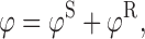
Abstract
This review is concerned with the motion of a point scalar charge, a point electric charge, and a point mass in a specified background spacetime. In each of the three cases the particle produces a field that behaves as outgoing radiation in the wave zone, and therefore removes energy from the particle. In the near zone the field acts on the particle and gives rise to a self-force that prevents the particle from moving on a geodesic of the background spacetime. The self-force contains both conservative and dissipative terms, and the latter are responsible for the radiation reaction. The work done by the self-force matches the energy radiated away by the particle.
The field’s action on the particle is difficult to calculate because of its singular nature: the field diverges at the position of the particle. But it is possible to isolate the field’s singular part and show that it exerts no force on the particle — its only effect is to contribute to the particle’s inertia. What remains after subtraction is a regular field that is fully responsible for the self-force. Because this field satisfies a homogeneous wave equation, it can be thought of as a free field that interacts with the particle; it is this interaction that gives rise to the self-force.
The mathematical tools required to derive the equations of motion of a point scalar charge, a point electric charge, and a point mass in a specified background spacetime are developed here from scratch. The review begins with a discussion of the basic theory of bitensors (Part I). It then applies the theory to the construction of convenient coordinate systems to chart a neighbourhood of the particle’s word line (Part II). It continues with a thorough discussion of Green’s functions in curved spacetime (Part III). The review presents a detailed derivation of each of the three equations of motion (Part IV). Because the notion of a point mass is problematic in general relativity, the review concludes (Part V) with an alternative derivation of the equations of motion that applies to a small body of arbitrary internal structure.
Introduction and summary
Invitation
The motion of a point electric charge in flat spacetime was the subject of active investigation since the early work of Lorentz, Abrahams, Poincaré, and Dirac [56], until Gralla, Harte, and Wald produced a definitive derivation of the equations motion [82] with all the rigour that one should demand, without recourse to postulates and renormalization procedures. (The field’s early history is well related in Ref. [154].) In 1960 DeWitt and Brehme [54] generalized Dirac’s result to curved spacetimes, and their calculation was corrected by Hobbs [95] several years later. In 1997 the motion of a point mass in a curved background spacetime was investigated by Mino, Sasaki, and Tanaka [130], who derived an expression for the particle’s acceleration (which is not zero unless the particle is a test mass); the same equations of motion were later obtained by Quinn and Wald [150] using an axiomatic approach. The case of a point scalar charge was finally considered by Quinn in 2000 [149], and this led to the realization that the mass of a scalar particle is not necessarily a constant of the motion.
This article reviews the achievements described in the preceding paragraph; it is concerned with the motion of a point scalar charge q, a point electric charge e, and a point mass m in a specified background spacetime with metric gαβ. These particles carry with them fields that behave as outgoing radiation in the wave zone. The radiation removes energy and angular momentum from the particle, which then undergoes a radiation reaction — its world line cannot be simply a geodesic of the background spacetime. The particle’s motion is affected by the near-zone field which acts directly on the particle and produces a self-force. In curved spacetime the self-force contains a radiation-reaction component that is directly associated with dissipative effects, but it contains also a conservative component that is not associated with energy or angular-momentum transport. The self-force is proportional to q2 in the case of a scalar charge, proportional to e2 in the case of an electric charge, and proportional to m2 in the case of a point mass.
In this review we derive the equations that govern the motion of a point particle in a curved background spacetime. The presentation is entirely self-contained, and all relevant materials are developed ab initio. The reader, however, is assumed to have a solid grasp of differential geometry and a deep understanding of general relativity. The reader is also assumed to have unlimited stamina, for the road to the equations of motion is a long one. One must first assimilate the basic theory of bitensors (Part I), then apply the theory to construct convenient coordinate systems to chart a neighbourhood of the particle’s world line (Part II). One must next formulate a theory of Green’s functions in curved spacetimes (Part III), and finally calculate the scalar, electromagnetic, and gravitational fields near the world line and figure out how they should act on the particle (Part IV). A dedicated reader, correctly skeptical that sense can be made of a point mass in general relativity, will also want to work through the last portion of the review (Part V), which provides a derivation of the equations of motion for a small, but physically extended, body; this reader will be reassured to find that the extended body follows the same motion as the point mass. The review is very long, but the satisfaction derived, we hope, will be commensurate.
In this introductory section we set the stage and present an impressionistic survey of what the review contains. This should help the reader get oriented and acquainted with some of the ideas and some of the notation. Enjoy!
Radiation reaction in flat spacetime
Let us first consider the relatively simple and well-understood case of a point electric charge e moving in flat spacetime [154, 101, 171]. The charge produces an electromagnetic vector potential Aα that satisfies the wave equation
 |
1.1 |
together with the Lorenz gauge condition ∂αAα = 0. (On page 294, Jackson [101] explains why the term “Lorenz gauge” is preferable to “Lorentz gauge”.) The vector jα is the charge’s current density, which is formally written in terms of a four-dimensional Dirac functional supported on the charge’s world line: the density is zero everywhere, except at the particle’s position where it is infinite. For concreteness we will imagine that the particle moves around a centre (perhaps another charge, which is taken to be fixed) and that it emits outgoing radiation. We expect that the charge will undergo a radiation reaction and that it will spiral down toward the centre. This effect must be accounted for by the equations of motion, and these must therefore include the action of the charge’s own field, which is the only available agent that could be responsible for the radiation reaction. We seek to determine this self-force acting on the particle.
An immediate difficulty presents itself: the vector potential, and also the electromagnetic field tensor, diverge on the particle’s world line, because the field of a point charge is necessarily infinite at the charge’s position. This behaviour makes it most difficult to decide how the field is supposed to act on the particle.
Difficult but not impossible. To find a way around this problem we note first that the situation considered here, in which the radiation is propagating outward and the charge is spiraling inward, breaks the time-reversal invariance of Maxwell’s theory. A specific time direction was adopted when, among all possible solutions to the wave equation, we chose  , the retarded solution, as the physically relevant solution. Choosing instead the advanced solution
 would produce a time-reversed picture in which the radiation is propagating inward and the charge is spiraling outward. Alternatively, choosing the linear superposition
 |
1.2 |
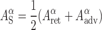
would restore time-reversal invariance: outgoing and incoming radiation would be present in equal amounts, there would be no net loss nor gain of energy by the system, and the charge would undergo no radiation reaction. In Eq. (1.2) the subscript ‘S’ stands for ‘symmetric’, as the vector potential depends symmetrically upon future and past.
Our second key observation is that while the potential of Eq. (1.2) does not exert a force on the charged particle, it is just as singular as the retarded potential in the vicinity of the world line. This follows from the fact that  , and
, and  all satisfy Eq. (1.1), whose source term is infinite on the world line. So while the wave-zone behaviours of these solutions are very different (with the retarded solution describing outgoing waves, the advanced solution describing incoming waves, and the symmetric solution describing standing waves), the three vector potentials share the same singular behaviour near the world line — all three electromagnetic fields are dominated by the particle’s Coulomb field and the different asymptotic conditions make no difference close to the particle. This observation gives us an alternative interpretation for the subscript ‘S’: it stands for ‘singular’ as well as ‘symmetric’.
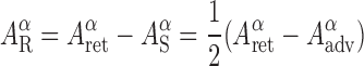
Because  is just as singular as
  , removing it from the retarded solution gives rise to a potential that is well behaved in a neighbourhood of the world line. And because
  is known not to affect the motion of the charged particle, this new potential must be entirely responsible for the radiation reaction. We therefore introduce the new potential
 |
1.3 |
and postulate that it, and it alone, exerts a force on the particle. The subscript ‘R’ stands for ‘regular’, because  is nonsingular on the world line. This property can be directly inferred from the fact that the regular potential satisfies the homogeneous version of Eq. (1.1),
  ; there is no singular source to produce a singular behaviour on the world line. Since
  satisfies the homogeneous wave equation, it can be thought of as a free radiation field, and the subscript ‘R’ could also stand for ‘radiative’.
The self-action of the charge’s own field is now clarified: a singular potential  can be removed from the retarded potential and shown not to affect the motion of the particle. What remains is a well-behaved potential
  that must be solely responsible for the radiation reaction. From the regular potential we form an electromagnetic field tensor
 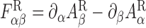 and we take the particle’s equations of motion to be
 |
1.4 |
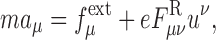
where uμ = dzμ/dτ is the charge’s four-velocity [zμ (τ) gives the description of the world line and τ is proper time], aμ = duμ/dτ its acceleration, m its (renormalized) mass, and  an external force also acting on the particle. Calculation of the regular field yields the more concrete expression
 |
1.5 |
in which the second term is the self-force that is responsible for the radiation reaction. We observe that the self-force is proportional to e2, it is orthogonal to the four-velocity, and it depends on the rate of change of the external force. This is the result that was first derived by Dirac [56]. (Dirac’s original expression actually involved the rate of change of the acceleration vector on the right-hand side. The resulting equation gives rise to the well-known problem of runaway solutions. To avoid such unphysical behaviour we have submitted Dirac’s equation to a reduction-of-order procedure whereby daν/dτ is replaced with  . This procedure is explained and justified, for example, in Refs. [112, 70], and further discussed in Section 24 below.)
To establish that the singular field exerts no force on the particle requires a careful analysis that is presented in the bulk of the paper. What really happens is that, because the particle is a monopole source for the electromagnetic field, the singular field is locally isotropic around the particle; it therefore exerts no force, but contributes to the particle’s inertia and renormalizes its mass. In fact, one could do without a decomposition of the field into singular and regular solutions, and instead construct the force by using the retarded field and averaging it over a small sphere around the particle, as was done by Quinn and Wald [150]. In the body of this review we will use both methods and emphasize the equivalence of the results. We will, however, give some emphasis to the decomposition because it provides a compelling physical interpretation of the self-force as an interaction with a free electromagnetic field.
Green’s functions in flat spacetime
To see how Eq. (1.5) can eventually be generalized to curved spacetimes, we introduce a new layer of mathematical formalism and show that the decomposition of the retarded potential into singular and regular pieces can be performed at the level of the Green’s functions associated with Eq. (1.1). The retarded solution to the wave equation can be expressed as
 |
1.6 |
in terms of the retarded Green’s function  . Here x = (t, x) is an arbitrary field point, x′ = (t′, x′) is a source point, and dV′:= d4x′; tensors at x are identified with unprimed indices, while primed indices refer to tensors at x′. Similarly, the advanced solution can be expressed as
 |
1.7 |
in terms of the advanced Green’s function  . The retarded Green’s function is zero whenever x lies outside of the future light cone of x′, and
  is infinite at these points. On the other hand, the advanced Green’s function is zero whenever x lies outside of the past light cone of x′, and
  is infinite at these points. The retarded and advanced Green’s functions satisfy the reciprocity relation
 |
1.8 |
this states that the retarded Green’s function becomes the advanced Green’s function (and vice versa) when x and x′ are interchanged.
From the retarded and advanced Green’s functions we can define a singular Green’s function by
 |
1.9 |
and a regular two-point function by
 |
1.10 |
By virtue of Eq. (1.8) the singular Green’s function is symmetric in its indices and arguments: 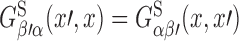 . The regular two-point function, on the other hand, is antisymmetric. The potential
 |
1.11 |
satisfies the wave equation of Eq. (1.1) and is singular on the world line, while
 |
1.12 |
satisfies the homogeneous equation □Aα = 0 and is well behaved on the world line.
Equation (1.6) implies that the retarded potential at x is generated by a single event in space-time: the intersection of the world line and x’s past light cone (see Figure 1). We shall call this the retarded point associated with x and denote it z (u); u is the retarded time, the value of the proper-time parameter at the retarded point. Similarly we find that the advanced potential of Eq. (1.7) is generated by the intersection of the world line and the future light cone of the field point x. We shall call this the advanced point associated with x and denote it z (v); v is the advanced time, the value of the proper-time parameter at the advanced point.
Figure 1.

In flat spacetime, the retarded potential at x depends on the particle’s state of motion at the retarded point z (u) on the world line; the advanced potential depends on the state of motion at the advanced point z (v).
Green’s functions in curved spacetime
In a curved spacetime with metric gαβ the wave equation for the vector potential becomes
 |
1.13 |
where □ = gαβ∇α∇β is the covariant wave operator and Rαβ is the spacetime’s Ricci tensor; the Lorenz gauge conditions becomes ∇αAα = 0, and ∇α denotes covariant differentiation. Retarded and advanced Green’s functions can be defined for this equation, and solutions to Eq. (1.13) take the same form as in Eqs. (1.6) and (1.7), except that dV′ now stands for  .
.
The causal structure of the Green’s functions is richer in curved spacetime: While in flat spacetime the retarded Green’s function has support only on the future light cone of x′, in curved spacetime its support extends inside the light cone as well;  is therefore nonzero when x ∈ I +(x′), which denotes the chronological future of x′. This property reflects the fact that in curved spacetime, electromagnetic waves propagate not just at the speed of light, but at all speeds smaller than or equal to the speed of light; the delay is caused by an interaction between the radiation and the spacetime curvature. A direct implication of this property is that the retarded potential at x is now generated by the point charge during its entire history prior to the retarded time u associated with x: the potential depends on the particle’s state of motion for all times τ ≤ u (see Figure 2).
Figure 2.

In curved spacetime, the retarded potential at x depends on the particle’s history before the retarded time u; the advanced potential depends on the particle’s history after the advanced time v.
Similar statements can be made about the advanced Green’s function and the advanced solution to the wave equation. While in flat spacetime the advanced Green’s function has support only on the past light cone of x′, in curved spacetime its support extends inside the light cone, and 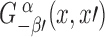 is nonzero when x ∈ I −(x′), which denotes the chronological past of x′. This implies that the advanced potential at x is generated by the point charge during its entire future history following the advanced time v associated with x: the potential depends on the particle’s state of motion for all times τ ≥ v.
The physically relevant solution to Eq. (1.13) is obviously the retarded potential  , and as in flat spacetime, this diverges on the world line. The cause of this singular behaviour is still the pointlike nature of the source, and the presence of spacetime curvature does not change the fact that the potential diverges at the position of the particle. Once more this behaviour makes it difficult to figure out how the retarded field is supposed to act on the particle and determine its motion. As in flat spacetime we shall attempt to decompose the retarded solution into a singular part that exerts no force, and a regular part that produces the entire self-force.
To decompose the retarded Green’s function into singular and regular parts is not a straightforward task in curved spacetime. The flat-spacetime definition for the singular Green’s function, Eq. (1.9), cannot be adopted without modification: While the combination half-retarded plus half-advanced Green’s functions does have the property of being symmetric, and while the resulting vector potential would be a solution to Eq. (1.13), this candidate for the singular Green’s function would produce a self-force with an unacceptable dependence on the particle’s future history. For suppose that we made this choice. Then the regular two-point function would be given by the combination half-retarded minus half-advanced Green’s functions, just as in flat spacetime. The resulting potential would satisfy the homogeneous wave equation, and it would be regular on the world line, but it would also depend on the particle’s entire history, both past (through the retarded Green’s function) and future (through the advanced Green’s function). More precisely stated, we would find that the regular potential at x depends on the particle’s state of motion at all times τ outside the interval u < τ < v; in the limit where x approaches the world line, this interval shrinks to nothing, and we would find that the regular potential is generated by the complete history of the particle. A self-force constructed from this potential would be highly noncausal, and we are compelled to reject these definitions for the singular and regular Green’s functions.
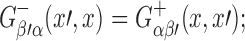
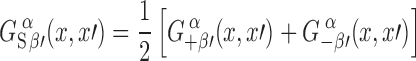
The proper definitions were identified by Detweiler and Whiting [53], who proposed the following generalization to Eq. (1.9):
 |
1.14 |
The two-point function  is introduced specifically to cure the pathology described in the preceding paragraph. It is symmetric in its indices and arguments, so that
  will be also (since the retarded and advanced Green’s functions are still linked by a reciprocity relation); and it is a solution to the homogeneous wave equation,
  , so that the singular, retarded, and advanced Green’s functions will all satisfy the same wave equation. Furthermore, and this is its key property, the two-point function is defined to agree with the advanced Green’s function when x is in the chronological past of
  when x ∈ I (x′). This ensures that
  vanishes when x is in the chronological past of x′. In fact, reciprocity implies that
  will also agree with the retarded Green’s function when x is in the chronological future of x′, and it follows that the symmetric Green’s function vanishes also when x is in the chronological future of x′.
The potential  constructed from the singular Green’s function can now be seen to depend on the particle’s state of motion at times τ restricted to the interval u ≤ τ ≤ v (see Figure 3). Because this potential satisfies Eq. (1.13), it is just as singular as the retarded potential in the vicinity of the world line. And because the singular Green’s function is symmetric in its arguments, the singular potential can be shown to exert no force on the charged particle. (This requires a lengthy analysis that will be presented in the bulk of the paper.)
Figure 3.

In curved spacetime, the singular potential at x depends on the particle’s history during the interval u ≤ τ ≤ v; for the regular potential the relevant interval is − ∞ < τ ≤ v.
The Detweiler-Whiting [53] definition for the regular two-point function is then
 |
1.15 |
The potential  constructed from this depends on the particle’s state of motion at all times τ prior to the advanced time v: τ ≤ v. Because this potential satisfies the homogeneous wave equation, it is well behaved on the world line and its action on the point charge is well defined. And because the singular potential
  can be shown to exert no force on the particle, we conclude that
  alone is responsible for the self-force.
From the regular potential we form an electromagnetic field tensor  and the curved-spacetime generalization to Eq. (1.4) is
 |
1.16 |
where uμ = dzμ/dτ is again the charge’s four-velocity, but aμ = Duμ/dτ is now its covariant acceleration.
World line and retarded coordinates
To flesh out the ideas contained in the preceding subsection we add yet another layer of mathematical formalism and construct a convenient coordinate system to chart a neighbourhood of the particle’s world line. In the next subsection we will display explicit expressions for the retarded, singular, and regular fields of a point electric charge.
Let γ be the world line of a point particle in a curved spacetime. It is described by parametric relations zμ (τ) in which τ is proper time. Its tangent vector is uμ = dzμ/dτ and its acceleration is aμ = Duμ/dτ; we shall also encounter ȧμ: = Daμ/dτ.
On γ we erect an orthonormal basis that consists of the four-velocity uμ and three spatial vectors  labelled by a frame index a = (1, 2, 3). These vectors satisfy the relations gμνuμuν = −1,
  , and
, and 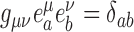 . We take the spatial vectors to be Fermi-Walker transported on the world line:
  , where
 |
1.17 |
are frame components of the acceleration vector; it is easy to show that Fermi-Walker transport preserves the orthonormality of the basis vectors. We shall use the tetrad to decompose various tensors evaluated on the world line. An example was already given in Eq. (1.17) but we shall also encounter frame components of the Riemann tensor,
 |
1.18 |
as well as frame components of the Ricci tensor,
 |
1.19 |
We shall use δab = diag(1, 1, 1) and its inverse δab = diag(1, 1, 1) to lower and raise frame indices, respectively.
Consider a point x in a neighbourhood of the world line γ. We assume that x is sufficiently close to the world line that a unique geodesic links x to any neighbouring point z on γ. The two-point function σ (x,z), known as Synge’s world function [169], is numerically equal to half the squared geodesic distance between z and x; it is positive if x and z are spacelike related, negative if they are timelike related, and σ (x, z) is zero if x and z are linked by a null geodesic. We denote its gradient ∂σ/∂zμ by σμ (x,z), and −σμ gives a meaningful notion of a separation vector (pointing from z tox).
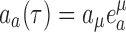
To construct a coordinate system in this neighbourhood we locate the unique point x′:= z (u) on γ which is linked to x by a future-directed null geodesic (this geodesic is directed from x′ to x); we shall refer to x′ as the retarded point associated with x, and u will be called the retarded time. To tensors at x′ we assign indices α′, β′, …; this will distinguish them from tensors at a generic point z (τ) on the world line, to which we have assigned indices μ, ν, …. We have σ (x, x′) = 0 and −σα′ (x, x′) is a null vector that can be interpreted as the separation between x′ and x.
The retarded coordinates of the point x are  where
where 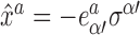 are the frame components of the separation vector. They come with a straightforward interpretation (see Figure 4). The invariant quantity
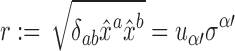 |
1.20 |
is an affine parameter on the null geodesic that links x to x′; it can be loosely interpreted as the time delay between x and x′ as measured by an observer moving with the particle. This therefore gives a meaningful notion of distance between x and the retarded point, and we shall call r the retarded distance between x and the world line. The unit vector
 |
1.21 |
is constant on the null geodesic that links x to x′. Because Ωa is a different constant on each null geodesic that emanates from x′, keeping u fixed and varying Ωa produces a congruence of null geodesics that generate the future light cone of the point x′ (the congruence is hypersurface orthogonal). Each light cone can thus be labelled by its retarded time u, each generator on a given light cone can be labelled by its direction vector Ωa, and each point on a given generator can be labelled by its retarded distance r. We therefore have a good coordinate system in a neighbourhood of γ.
Figure 4.

Retarded coordinates of a point x relative to a world line γ. The retarded time u selects a particular null cone, the unit vector  selects a particular generator of this null cone, and the retarded distance r selects a particular point on this generator.
To tensors at x we assign indices α, β, …. These tensors will be decomposed in a tetrad  that is constructed as follows: Given x we locate its associated retarded point x′ on the world line, as well as the null geodesic that links these two points; we then take the tetrad
  at x′ and parallel transport it to x along the null geodesic to obtain
  .
.
Retarded, singular, and regular electromagnetic fields of a point electric charge
The retarded solution to Eq. (1.13) is
 |
1.22 |
where the integration is over the world line of the point electric charge. Because the retarded solution is the physically relevant solution to the wave equation, it will not be necessary to put a label ‘ret’ on the vector potential.
From the vector potential we form the electromagnetic field tensor Fαβ, which we decompose in the tetrad  introduced at the end of Section 1.5. We then express the frame components of the field tensor in retarded coordinates, in the form of an expansion in powers of r. This gives
 |
1.23 |
 |
1.24 |
where
 |
1.25 |
are the frame components of the “tail part” of the field, which is given by
 |
1.26 |
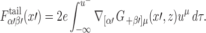
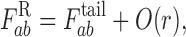
In these expressions, all tensors (or their frame components) are evaluated at the retarded point x′:= z (u) associated with x; for example,  . The tail part of the electromagnetic field tensor is written as an integral over the portion of the world line that corresponds to the interval −∞ < τ ≤ u− := u − 0+; this represents the past history of the particle. The integral is cut short at u to avoid the singular behaviour of the retarded Green’s function when z (τ) coincides with x′; the portion of the Green’s function involved in the tail integral is smooth, and the singularity at coincidence is completely accounted for by the other terms in Eqs. (1.23) and (1.24).
The expansion of Fαβ (x) near the world line does indeed reveal many singular terms. We first recognize terms that diverge when r → 0; for example the Coulomb field Fa0 diverges as r−2 when we approach the world line. But there are also terms that, though they stay bounded in the limit, possess a directional ambiguity at r = 0; for example Fab contains a term proportional to Ra0bcΩc whose limit depends on the direction of approach.
This singularity structure is perfectly reproduced by the singular field  obtained from the potential
 |
1.27 |
where  is the singular Green’s function of Eq. (1.14). Near the world line the singular field is given by
 |
1.28 |
 |
1.29 |
Comparison of these expressions with Eqs. (1.23) and (1.24) does indeed reveal that all singular terms are shared by both fields.
The difference between the retarded and singular fields defines the regular field  . Its frame components are
 |
1.30 |
 |
1.31 |
and at x′ the regular field becomes
 |
1.32 |
where 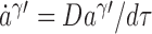 is the rate of change of the acceleration vector, and where the tail term was given by Eq. (1.26). We see that
  is a regular tensor field, even on the world line.
Motion of an electric charge in curved spacetime
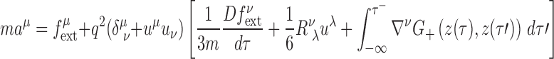
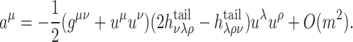
We have argued in Section 1.4 that the self-force acting on a point electric charge is produced by the regular field, and that the charge’s equations of motion should take the form of 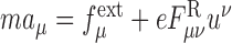 , where
  is an external force also acting on the particle. Substituting Eq. (1.32) gives
 |
1.33 |
in which all tensors are evaluated at z (τ), the current position of the particle on the world line. The primed indices in the tail integral refer to a point z (τ′) which represents a prior position; the integration is cut short at τ′ = τ− := τ − 0+ to avoid the singular behaviour of the retarded Green’s function at coincidence. To get Eq. (1.33) we have reduced the order of the differential equation by replacing ȧν with  on the right-hand side; this procedure was explained at the end of Section 1.2.
Equation (1.33) is the result that was first derived by DeWitt and Brehme [54] and later corrected by Hobbs [95]. (The original version of the equation did not include the Ricci-tensor term.) In flat spacetime the Ricci tensor is zero, the tail integral disappears (because the Green’s function vanishes everywhere within the domain of integration), and Eq. (1.33) reduces to Dirac’s result of Eq. (1.5). In curved spacetime the self-force does not vanish even when the electric charge is moving freely, in the absence of an external force: it is then given by the tail integral, which represents radiation emitted earlier and coming back to the particle after interacting with the spacetime curvature. This delayed action implies that in general, the self-force is nonlocal in time: it depends not only on the current state of motion of the particle, but also on its past history. Lest this behaviour should seem mysterious, it may help to keep in mind that the physical process that leads to Eq. (1.33) is simply an interaction between the charge and a free electromagnetic field  ; it is this field that carries the information about the charge’s past.
Motion of a scalar charge in curved spacetime
The dynamics of a point scalar charge can be formulated in a way that stays fairly close to the electromagnetic theory. The particle’s charge q produces a scalar field Φ(x) which satisfies a wave equation
 |
1.34 |
that is very similar to Eq. (1.13). Here, R is the spacetime’s Ricci scalar, and ξ is an arbitrary coupling constant; the scalar charge density μ (x) is given by a four-dimensional Dirac functional supported on the particle’s world line γ. The retarded solution to the wave equation is
 |
1.35 |
where G+(x, z) is the retarded Green’s function associated with Eq. (1.34). The field exerts a force on the particle, whose equations of motion are
 |
1.36 |
where m is the particle’s mass; this equation is very similar to the Lorentz-force law. But the dynamics of a scalar charge comes with a twist: If Eqs. (1.34) and (1.36) are to follow from a variational principle, the particle’s mass should not be expected to be a constant of the motion. It is found instead to satisfy the differential equation
 |
1.37 |
and in general m will vary with proper time. This phenomenon is linked to the fact that a scalar field has zero spin: the particle can radiate monopole waves and the radiated energy can come at the expense of the rest mass.
The scalar field of Eq. (1.35) diverges on the world line and its singular part ΦS(x) must be removed before Eqs. (1.36) and (1.37) can be evaluated. This procedure produces the regular field ΦR(x), and it is this field (which satisfies the homogeneous wave equation) that gives rise to a self-force. The gradient of the regular field takes the form of
 |
1.38 |
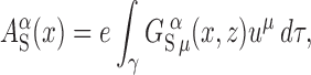
when it is evaluated on the world line. The last term is the tail integral
 |
1.39 |
and this brings the dependence on the particle’s past.
Substitution of Eq. (1.38) into Eqs. (1.36) and (1.37) gives the equations of motion of a point scalar charge. (At this stage we introduce an external force  and reduce the order of the differential equation.) The acceleration is given by
 |
1.40 |
and the mass changes according to
 |
1.41 |
These equations were first derived by Quinn [149]. (His analysis was restricted to a minimally coupled scalar field, so that ξ = 0 in his expressions. We extended Quinn’s results to an arbitrary coupling counstant for this review.)
In flat spacetime the Ricci-tensor term and the tail integral disappear and Eq. (1.40) takes the form of Eq. (1.5) with q2/(3m) replacing the factor of 2e2/(3m). In this simple case Eq. (1.41) reduces to dm/dτ = 0 and the mass is in fact a constant. This property remains true in a conformally flat spacetime when the wave equation is conformally invariant (ξ = 1/6): in this case the Green’s function possesses only a light-cone part and the right-hand side of Eq. (1.41) vanishes. In generic situations the mass of a point scalar charge will vary with proper time.
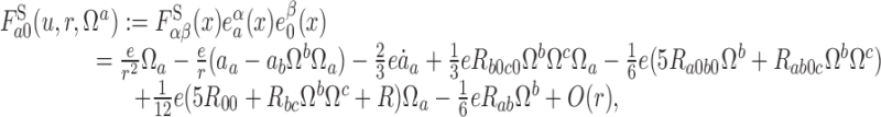
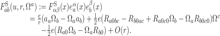
Motion of a point mass, or a small body, in a background spacetime
The case of a point mass moving in a specified background spacetime presents itself with a serious conceptual challenge, as the fundamental equations of the theory are nonlinear and the very notion of a “point mass” is somewhat misguided. Nevertheless, to the extent that the perturbation haβ (x) created by the point mass can be considered to be “small”, the problem can be formulated in close analogy with what was presented before.
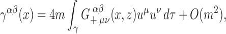
We take the metric gαβ of the background spacetime to be a solution of the Einstein field equations in vacuum. (We impose this condition globally.) We describe the gravitational perturbation produced by a point particle of mass m in terms of trace-reversed potentials γαβ defined by
 |
1.42 |
where haβ is the difference between gαβ, the actual metric of the perturbed spacetime, and gαβ. The potentials satisfy the wave equation
 |
1.43 |
together with the Lorenz gauge condition γαβ;β = 0. Here and below, covariant differentiation refers to a connection that is compatible with the background metric, □ = gαβ ∇α ∇β is the wave operator for the background spacetime, and Tαβ is the energy-momentum tensor of the point mass; this is given by a Dirac distribution supported on the particle’s world line γ. The retarded solution is
 |
1.44 |
where  is the retarded Green’s function associated with Eq. (1.43). The perturbation haβ (x) can be recovered by inverting Eq. (1.42).
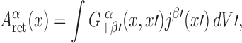
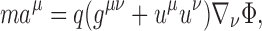
Equations of motion for the point mass can be obtained by formally demanding that the motion be geodesic in the perturbed spacetime with metric gαβ = gαβ + hαβ. After a mapping to the background spacetime, the equations of motion take the form of
 |
1.45 |
The acceleration is thus proportional to m; in the test-mass limit the world line of the particle is a geodesic of the background spacetime.
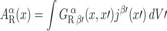
We now remove  from the retarded perturbation and postulate that it is the regular field
  that should act on the particle. (Note that
  satisfies the same wave equation as the retarded potentials, but that
  is a free gravitational field that satisfies the homogeneous wave equation.) On the world line we have
 |
1.46 |
where the tail term is given by
 |
1.47 |
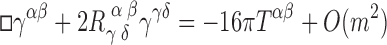
When Eq. (1.46) is substituted into Eq. (1.45) we find that the terms that involve the Riemann tensor cancel out, and we are left with
 |
1.48 |
Only the tail integral appears in the final form of the equations of motion. It involves the current position z (τ) of the particle, at which all tensors with unprimed indices are evaluated, as well as all prior positions z (τ′), at which tensors with primed indices are evaluated. As before the integral is cut short at τ′ = τ−:= τ − 0+ to avoid the singular behaviour of the retarded Green’s function at coincidence.
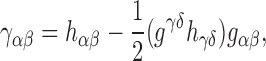
The equations of motion of Eq. (1.48) were first derived by Mino, Sasaki, and Tanaka [130], and then reproduced with a different analysis by Quinn and Wald [150]. They are now known as the MiSaTaQuWa equations of motion. As noted by these authors, the MiSaTaQuWa equation has the appearance of the geodesic equation in a metric  . Detweiler and Whiting [53] have contributed the more compelling interpretation that the motion is actually geodesic in a spacetime with metric
  . The distinction is important: Unlike the first version of the metric, the Detweiler-Whiting metric is regular on the world line and satisfies the Einstein field equations in vacuum; and because it is a solution to the field equations, it can be viewed as a physical metric — specifically, the metric of the background spacetime perturbed by a free field produced by the particle at an earlier stage of its history.
While Eq. (1.48) does indeed give the correct equations of motion for a small mass m moving in a background spacetime with metric gαβ, the derivation outlined here leaves much to be desired — to what extent should we trust an analysis based on the existence of a point mass? As a partial answer to this question, Mino, Sasaki, and Tanaka [130] produced an alternative derivation of their result, which involved a small nonrotating black hole instead of a point mass. In this alternative derivation, the metric of the black hole perturbed by the tidal gravitational field of the external universe is matched to the metric of the background spacetime perturbed by the moving black hole. Demanding that this metric be a solution to the vacuum field equations determines the motion of the black hole: it must move according to Eq. (1.48). This alternative derivation (which was given a different implementation in Ref. [142]) is entirely free of singularities (except deep within the black hole), and it suggests that that the MiSaTaQuWa equations can be trusted to describe the motion of any gravitating body in a curved background spacetime (so long as the body’s internal structure can be ignored). This derivation, however, was limited to the case of a non-rotating black hole, and it relied on a number of unjustified and sometimes unstated assumptions [83, 144, 145]. The conclusion was made firm by the more rigorous analysis of Gralla and Wald [83] (as extended by Pound [144]), who showed that the MiSaTaQuWa equations apply to any sufficiently compact body of arbitrary internal structure.
It is important to understand that unlike Eqs. (1.33) and (1.40), which are true tensorial equations, Eq. (1.48) reflects a specific choice of coordinate system and its form would not be preserved under a coordinate transformation. In other words, the MiSaTaQuWa equations are not gauge invariant, and they depend upon the Lorenz gauge condition γαβ;β = O (m2). Barack and Ori [17] have shown that under a coordinate transformation of the form xα → xα+ ξα, where xα are the coordinates of the background spacetime and ξα is a smooth vector field of order m, the particle’s acceleration changes according to aμ → aμ + a [ξ ]μ, where
 |
1.49 |
is the “gauge acceleration”; D2ξν/dτ2 = (ξν;μuμ);ρuρ is the second covariant derivative of ξν in the direction of the world line. This implies that the particle’s acceleration can be altered at will by a gauge transformation; ξα could even be chosen so as to produce aμ = 0, making the motion geodesic after all. This observation provides a dramatic illustration of the following point: The MiSaTaQuWa equations of motion are not gauge invariant and they cannot by themselves produce a meaningful answer to a well-posed physical question; to obtain such answers it is necessary to combine the equations of motion with the metric perturbation hαβ so as to form gauge-invariant quantities that will correspond to direct observables. This point is very important and cannot be over-emphasized.
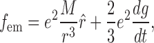
The gravitational self-force possesses a physical significance that is not shared by its scalar and electromagnetic analogues, because the motion of a small body in the strong gravitational field of a much larger body is a problem of direct relevance to gravitational-wave astronomy. Indeed, extreme-mass-ratio inspirals, involving solar-mass compact objects moving around massive black holes of the sort found in galactic cores, have been identified as promising sources of low-frequency gravitational waves for space-based interferometric detectors such as the proposed Laser Interferometer Space Antenna (LISA [115]). These systems involve highly eccentric, nonequatorial, and relativistic orbits around rapidly rotating black holes, and the waves produced by such orbital motions are rich in information concerning the strongest gravitational fields in the Universe. This information will be extractable from the LISA data stream, but the extraction depends on sophisticated data-analysis strategies that require a detailed and accurate modeling of the source. This modeling involves formulating the equations of motion for the small body in the field of the rotating black hole, as well as a consistent incorporation of the motion into a wave-generation formalism. In short, the extraction of this wealth of information relies on a successful evaluation of the gravitational self-force.
The finite-mass corrections to the orbital motion are important. For concreteness, let us assume that the orbiting body is a black hole of mass m = 10 M⊙ and that the central black hole has a mass M = 106 M⊙. Let us also assume that the small black hole is in the deep field of the large hole, near the innermost stable circular orbit, so that its orbital period P is of the order of minutes. The gravitational waves produced by the orbital motion have frequencies f of the order of the mHz, which is well within LISA’s frequency band. The radiative losses drive the orbital motion toward a final plunge into the large black hole; this occurs over a radiation-reaction timescale (M/m)P of the order of a year, during which the system will go through a number of wave cycles of the order of M/m = 105. The role of the gravitational self-force is precisely to describe this orbital evolution toward the final plunge. While at any given time the self-force provides fractional corrections of order m/M = 10−5 to the motion of the small black hole, these build up over a number of orbital cycles of order M/m = 105 to produce a large cumulative effect. As will be discussed in some detail in Section 2.6, the gravitational self-force is important, because it drives large secular changes in the orbital motion of an extreme-mass-ratio binary.
Case study: static electric charge in Schwarzschild spacetime
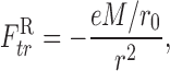
One of the first self-force calculations ever performed for a curved spacetime was presented by Smith and Will [163]. They considered an electric charge e held in place at position r = r0 outside a Schwarzschild black hole of mass M. Such a static particle must be maintained in position with an external force that compensates for the black hole’s attraction. For a particle without electric charge this force is directed outward, and its radial component in Schwarzschild coordinates is given by  , where m is the particle’s mass, f:= 1 − 2M/r0 is the usual metric factor, and a prime indicates differentiation with respect to r0, so that
  . Smith and Will found that for a particle of charge e, the external force is given instead by
 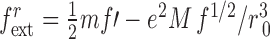 . The second term is contributed by the electromagnetic self-force, and implies that the external force is smaller for a charged particle. This means that the electromagnetic self-force acting on the particle is directed outward and given by
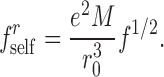 |
1.50 |
This is a repulsive force. It was shown by Zel’nikov and Frolov [186] that the same expression applies to a static charge outside a Reissner-Nordström black hole of mass M and charge Q, provided that f is replaced by the more general expression 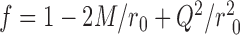 .
.
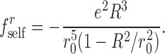
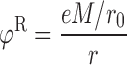
The repulsive nature of the electromagnetic self-force acting on a static charge outside a black hole is unexpected. In an attempt to gain some intuition about this result, it is useful to recall that a black-hole horizon always acts as perfect conductor, because the electrostatic potential φ:= −At is necessarily uniform across its surface. It is then tempting to imagine that the self-force should result from a fictitious distribution of induced charge on the horizon, and that it could be estimated on the basis of an elementary model involving a spherical conductor. Let us, therefore, calculate the electric field produced by a point charge e situated outside a spherical conductor of radius R. The charge is placed at a distance r0 from the centre of the conductor, which is taken at first to be grounded. The electrostatic potential produced by the charge can easily be obtained with the method of images. It is found that an image charge e′ = −eR/r0 is situated at a distance r′0 = R2/r0 from the centre of the conductor, and the potential is given by φ = e/s + e′/s′, where s is the distance to the charge, while s′ is the distance to the image charge. The first term can be identified with the singular potential φs, and the associated electric field exerts no force on the point charge. The second term is the regular potential φR, and the associated field is entirely responsible for the self-force. The regular electric field is 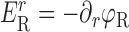 , and the self-force is
 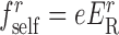 . A simple computation returns
 |
1.51 |
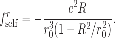
This is an attractive self-force, because the total induced charge on the conducting surface is equal to e′, which is opposite in sign to e. With R identified with M up to a numerical factor, we find that our intuition has produced the expected factor of  , but that it gives rise to the wrong sign for the self-force. An attempt to refine this computation by removing the net charge e′ on the conductor (to mimic more closely the black-hole horizon, which cannot support a net charge) produces a wrong dependence on r0 in addition to the same wrong sign. In this case the conductor is maintained at a constant potential φ0 = −e′/R, and the situation involves a second image charge −e′ situated at r = 0. It is easy to see that in this case,
 |
1.52 |
This is still an attractive force, which is weaker than the force of Eq. (1.51) by a factor of (R/r0)2; the force is now exerted by an image dipole instead of a single image charge.
The computation of the self-force in the black-hole case is almost as straightforward. The exact solution to Maxwell’s equations that describes a point charge e situated r = r0 and θ = 0 in the Schwarzschild spacetime is given by
 |
1.53 |
where
 |
1.54 |
is the solution first discovered by Copson in 1928 [43], while
 |
1.55 |
is the monopole field that was added by Linet [114] to obtain the correct asymptotic behaviour φ ∼ e/r when r is much larger than r0. It is easy to see that Copson’s potential behaves as e(1 − M/r0)/r at large distances, which reveals that in addition to e, φs comes with an additional (and unphysical) charge −eM/r0 situated at r = 0. This charge must be removed by adding to φs a potential that (i) is a solution to the vacuum Maxwell equations, (ii) is regular everywhere except at r = 0, and (iii) carries the opposite charge +eM/r0; this potential must be a pure monopole, because higher multipoles would produce a singularity on the horizon, and it is given uniquely by φR. The Copson solution was generalized to Reissner-Nordström spacetime by Léauté and Linet [113], who also showed that the regular potential of Eq. (1.55) requires no modification.
The identification of Copson’s potential with the singular potential φs is dictated by the fact that its associated electric field  is isotropic around the charge e and therefore exerts no force. The self-force comes entirely from the monopole potential, which describes a (fictitious) charge +eM/r0 situated at r = 0. Because this charge is of the same sign as the original charge e, the self-force is repulsive. More precisely stated, we find that the regular piece of the electric field is given by
 |
1.56 |
and that it produces the self-force of Eq. (1.50). The simple picture described here, in which the electromagnetic self-force is produced by a fictitious charge eM/r0 situated at the centre of the black hole, is not easily extracted from the derivation presented originally by Smith and Will [163]. To the best of our knowledge, the monopolar origin of the self-force was first noticed by Alan Wiseman [185]. (In his paper, Wiseman computed the scalar self-force acting on a static particle in Schwarzschild spacetime, and found a zero answer. In this case, the analogue of the Copson solution for the scalar potential happens to satisfy the correct asymptotic conditions, and there is no need to add another solution to it. Because the scalar potential is precisely equal to the singular potential, the self-force vanishes.)
We should remark that the identification of φS and φR with the Detweiler-Whiting singular and regular fields, respectively, is a matter of conjecture. Although φS and φR satisfy the essential properties of the Detweiler-Whiting decomposition — being, respectively, a regular homogenous solution and a singular solution sourced by the particle — one should accept the possibility that they may not be the actual Detweiler-Whiting fields. It is a topic for future research to investigate the precise relation between the Copson field and the Detweiler-Whiting singular field.
It is instructive to compare the electromagnetic self-force produced by the presence of a grounded conductor to the self-force produced by the presence of a black hole. In the case of a conductor, the total induced charge on the conducting surface is e′ = −eR/r0, and it is this charge that is responsible for the attractive self-force; the induced charge is supplied by the electrodes that keep the conductor grounded. In the case of a black hole, there is no external apparatus that can supply such a charge, and the total induced charge on the horizon necessarily vanishes. The origin of the self-force is therefore very different in this case. As we have seen, the self-force is produced by a fictitious charge eM/r0 situated at the centre of black hole; and because this charge is positive, the self-force is repulsive.
Organization of this review
After a detailed review of the literature in Section 2, the main body of the review begins in Part I (Sections 3 to 7) with a description of the general theory of bitensors, the name designating tensorial functions of two points in spacetime. We introduce Synge’s world function σ (x, x′) and its derivatives in Section 3, the parallel propagator  in Section 5, and the van Vleck determinant Δ(x, x′) in Section 7. An important portion of the theory (covered in Sections 4 and 6) is concerned with the expansion of bitensors when x is very close to x′; expansions such as those displayed in Eqs. (1.23) and (1.24) are based on these techniques. The presentation in Part I borrows heavily from Synge’s book [169] and the article by DeWitt and Brehme [54]. These two sources use different conventions for the Riemann tensor, and we have adopted Synge’s conventions (which agree with those of Misner, Thorne, and Wheeler [131]). The reader is therefore warned that formulae derived in Part I may look superficially different from those found in De Witt and Brehme.
In Part II (Sections 8 to 11) we introduce a number of coordinate systems that play an important role in later parts of the review. As a warmup exercise we first construct (in Section 8) Riemann normal coordinates in a neighbourhood of a reference point x′. We then move on (in Section 9) to Fermi normal coordinates [122], which are defined in a neighbourhood of a world line γ. The retarded coordinates, which are also based at a world line and which were briefly introduced in Section 1.5, are covered systematically in Section 10. The relationship between Fermi and retarded coordinates is worked out in Section 11, which also locates the advanced point z (v) associated with a field point x. The presentation in Part II borrows heavily from Synge’s book [169]. In fact, we are much indebted to Synge for initiating the construction of retarded coordinates in a neighbourhood of a world line. We have implemented his program quite differently (Synge was interested in a large neighbourhood of the world line in a weakly curved spacetime, while we are interested in a small neighbourhood in a strongly curved spacetime), but the idea is originally his.
In Part III (Sections 12 to 16) we review the theory of Green’s functions for (scalar, vectorial, and tensorial) wave equations in curved spacetime. We begin in Section 12 with a pedagogical introduction to the retarded and advanced Green’s functions for a massive scalar field in flat spacetime; in this simple context the all-important Hadamard decomposition [88] of the Green’s function into “light-cone” and “tail” parts can be displayed explicitly. The invariant Dirac functional is defined in Section 13 along with its restrictions on the past and future null cones of a reference point x′. The retarded, advanced, singular, and regular Green’s functions for the scalar wave equation are introduced in Section 14. In Sections 15 and 16 we cover the vectorial and tensorial wave equations, respectively. The presentation in Part III is based partly on the paper by DeWitt and Brehme [54], but it is inspired mostly by Friedlander’s book [71]. The reader should be warned that in one important aspect, our notation differs from the notation of DeWitt and Brehme: While they denote the tail part of the Green’s function by −v (x, x′), we have taken the liberty of eliminating the silly minus sign and call it instead +V (x, x′). The reader should also note that all our Green’s functions are normalized in the same way, with a factor of −4π multiplying a four-dimensional Dirac functional of the right-hand side of the wave equation. (The gravitational Green’s function is sometimes normalized with a −16π on the right-hand side.)
In Part IV (Sections 17 to 19) we compute the retarded, singular, and regular fields associated with a point scalar charge (Section 17), a point electric charge (Section 18), and a point mass (Section 19). We provide two different derivations for each of the equations of motion. The first type of derivation was outlined previously: We follow Detweiler and Whiting [53] and postulate that only the regular field exerts a force on the particle. In the second type of derivation we take guidance from Quinn and Wald [150] and postulate that the net force exerted on a point particle is given by an average of the retarded field over a surface of constant proper distance orthogonal to the world line — this rest-frame average is easily carried out in Fermi normal coordinates. The averaged field is still infinite on the world line, but the divergence points in the direction of the acceleration vector and it can thus be removed by mass renormalization. Such calculations show that while the singular field does not affect the motion of the particle, it nonetheless contributes to its inertia.
In Part V (Sections 20 to 23), we show that at linear order in the body’s mass m, an extended body behaves just as a point mass, and except for the effects of the body’s spin, the world line representing its mean motion is governed by the MiSaTaQuWa equation. At this order, therefore, the picture of a point particle interacting with its own field, and the results obtained from this picture, is justified. Our derivation utilizes the method of matched asymptotic expansions, with an inner expansion accurate near the body and an outer expansion accurate everywhere else. The equation of motion of the body’s world line, suitably defined, is calculated by solving the Einstein equation in a buffer region around the body, where both expansions are accurate.
Concluding remarks are presented in Section 24, and technical developments that are required in Part V are relegated to Appendices. Throughout this review we use geometrized units and adopt the notations and conventions of Misner, Thorne, and Wheeler [131].
Computing the self-force: a 2010 literature survey
Much progress has been achieved in the development of practical methods for computing the self-force. We briefly summarize these efforts in this section, with the goal of introducing the main ideas and some key issues. A more detailed coverage of the various implementations can be found in Barack’s excellent review [9]. The 2005 collection of reviews published in Classical and Quantum Gravity [118] is also recommended for an introduction to the various aspects of self-force theory and numerics. Among our favourites in this collection are the reviews by Detweiler [49] and Whiting [183].
An important point to bear in mind is that all the methods covered here mainly compute the self-force on a particle moving on a fixed world line of the background spacetime. A few numerical codes based on the radiative approximation have allowed orbits to evolve according to energy and angular-momentum balance. As will be emphasized below, however, these calculations miss out on important conservative effects that are only accounted for by the full self-force. Work is currently underway to develop methods to let the self-force alter the motion of the particle in a self-consistent manner.
Early work: DeWitt and DeWitt; Smith and Will
The first evaluation of the electromagnetic self-force in curved spacetime was carried out by DeWitt and DeWitt [132] for a charge moving freely in a weakly curved spacetime characterized by a Newtonian potential Φ ≪ 1. In this context the right-hand side of Eq. (1.33) reduces to the tail integral, because the particle moves in a vacuum region of the spacetime, and there is no external force acting on the charge. They found that the spatial components of the self-force are given by
 |
2.1 |
where M is the total mass contained in the spacetime, r = |x| is the distance from the centre of mass,  , and g = −∇Φ is the Newtonian gravitational field. (In these expressions the boldfaced symbols represent vectors in three-dimensional flat space.) The first term on the right-hand side of Eq. (2.1) is a conservative correction to the Newtonian force mg. The second term is the standard radiation-reaction force; although it comes from the tail integral, this is the same result that would be obtained in flat spacetime if an external force mg were acting on the particle. This agreement is necessary, but remarkable!
A similar expression was obtained by Pfenning and Poisson [141] for the case of a scalar charge. Here
 |
2.2 |
where ξ is the coupling of the scalar field to the spacetime curvature; the conservative term disappears when the field is minimally coupled. Pfenning and Poisson also computed the gravitational self-force acting on a point mass moving in a weakly curved spacetime. The expression they obtained is in complete agreement (within its domain of validity) with the standard post-Newtonian equations of motion.
The force required to hold an electric charge in place in a Schwarzschild spacetime was computed, without approximations, by Smith and Will [163]. As we reviewed previously in Section 1.10, the self-force contribution to the total force is given by
 |
2.3 |
where M is the black-hole mass, r the position of the charge (in Schwarzschild coordinates), and f:= 1 − 2M/r. When r ≫ M, this expression agrees with the conservative term in Eq. (2.1). This result was generalized to Reissner-Nordström spacetime by Zel’nikov and Frolov [186]. Wiseman [185] calculated the self-force acting on a static scalar charge in Schwarzschild spacetime. He found that in this case the self-force vanishes. This result is not incompatible with Eq. (2.2), even for nonminimal coupling, because the computation of the weak-field self-force requires the presence of matter, while Wiseman’s scalar charge lives in a purely vacuum spacetime.
Mode-sum method
Self-force calculations involving a sum over modes were pioneered by Barack and Ori [16, 7], and the method was further developed by Barack, Ori, Mino, Nakano, and Sasaki [15, 8, 18, 20, 19, 127]; a somewhat related approach was also considered by Lousto [117]. It has now emerged as the method of choice for self-force calculations in spacetimes such as Schwarzschild and Kerr. Our understanding of the method was greatly improved by the Detweiler-Whiting decomposition [53] of the retarded field into singular and regular pieces, as outlined in Sections 1.4 and 1.8, and subsequent work by Detweiler, Whiting, and their collaborators [51].
Detweiler-Whiting decomposition; mode decomposition; regularization parameters
For simplicity we consider the problem of computing the self-force acting on a particle with a scalar charge q moving on a world line γ. (The electromagnetic and gravitational problems are conceptually similar, and they will be discussed below.) The potential Φ produced by the particle satisfies Eq. (1.34), which we rewrite schematically as
 |
2.4 |
where □ is the wave operator in curved spacetime, and δ (x, z) represents a distributional source that depends on the world line γ through its coordinate representation z (τ). From the perspective of the Detweiler-Whiting decomposition, the scalar self-force is given by
 |
2.5 |
where Φ, ΦS, and ΦR are the retarded, singular, and regular potentials, respectively. To evaluate the self-force, then, is to compute the gradient of the regular potential.
From the point of view of Eq. (2.5), the task of computing the self-force appears conceptually straightforward: Either (i) compute the retarded and singular potentials, subtract them, and take a gradient of the difference; or (ii) compute the gradients of the retarded and singular potentials, and then subtract the gradients. Indeed, this is the basic idea for most methods of self-force computations. However, the apparent simplicity of this sequence of steps is complicated by the following facts: (i) except for a very limited number of cases, the retarded potential of a point particle cannot be computed analytically and must therefore be obtained by numerical means; and (ii) both the retarded and singular potential diverge at the particle’s position. Thus, any sort of subtraction will generally have to be performed numerically, and for this to be possible, one requires representations of the retarded and singular potentials (and/or their gradients) in terms of finite quantities.
In a mode-sum method, these difficulties are overcome with a decomposition of the potential in spherical-harmonic functions:
 |
2.6 |
When the background spacetime is spherically symmetric, Eq. (2.4) gives rise to a fully decoupled set of reduced wave equations for the mode coefficients Φlm (t, r), and these are easily integrated with simple numerical methods. The dimensional reduction of the wave equation implies that each Φlm (t, r) is finite and continuous (though nondifferentiable) at the position of the particle. There is, therefore, no obstacle to evaluating each l-mode of the field, defined by
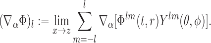 |
2.7 |
The sum over modes, however, must reproduce the singular field evaluated at the particle’s position, and this is infinite; the mode sum, therefore, does not converge.
Fortunately, there is a piece of each l-mode that does not contribute to the self-force, and that can be subtracted out; this piece is the corresponding l-mode of the singular field ∇α ΦS. Because the retarded and singular fields share the same singularity structure near the particle’s world line (as described in Section 1.6), the subtraction produces a mode decomposition of the regular field ∇αΦR. And because this field is regular at the particle’s position, the sum over all modes q (∇a ΦR,)l is guaranteed to converge to the correct value for the self-force. The key to the mode-sum method, therefore, is the ability to express the singular field as a mode decomposition.
This can be done because the singular field, unlike the retarded field, can always be expressed as a local expansion in powers of the distance to the particle; such an expansion was displayed in Eqs. (1.28) and (1.29). (In a few special cases the singular field is actually known exactly [43, 114, 33, 86, 162].) This local expansion can then be turned into a multipole decomposition. Barack and Ori [18, 15, 20, 19, 9], and then Mino, Nakano, and Sasaki [127], were the first to show that this produces the following generic structure:
 |
2.8 |
where Aα, Bα, Cα, and so on are l-independent functions that depend on the choice of field (i.e., scalar, electromagnetic, or gravitational), the choice of spacetime, and the particle’s state of motion. These so-called regularization parameters are now ubiquitous in the self-force literature, and they can all be determined from the local expansion for the singular field. The number of regularization parameters that can be obtained depends on the accuracy of the expansion. For example, expansions accurate through order r0 such as Eqs. (1.28) and (1.29) permit the determination of Aα, Bα, and Cα; to obtain Dα one requires the terms of order r, and to get Eα the expansion must be carried out through order r2. The particular polynomials in l that accompany the regularization parameters were first identified by Detweiler and his collaborators [51]. Because the Dα term is generated by terms of order r in the local expansion of the singular field, the sum of  from l = 0 to l = ∞ evaluates to zero. The sum of the polynomial in front of Eα also evaluates to zero, and this property is shared by all remaining terms in Eq. (2.8).
Mode sum
With these elements in place, the self-force is finally computed by implementing the mode-sum formula
 |
2.9 |
where the infinite sum over l is truncated to a maximum mode number L. (This truncation is necessary in practice, because in general the modes must be determined numerically.) The remainder consists of the remaining terms in the sum, from l = L + 1 to l = ∞; it is easy to see that since the next regularization term would scale as l−6 for large l, the remainder scales as L−5, and can be made negligible by summing to a suitably large value of l. This observation motivates the inclusion of the Dα and Eα terms within the mode sum, even though their complete sums evaluate to zero. These terms are useful because the sum must necessarily be truncated, and they permit a more rapid convergence of the mode sum. For example, exclusion of the Dα and Eα terms in Eq. (2.9) would produce a remainder that scales as L−1 instead of L−5; while this is sufficient for convergence, the rate of convergence is too slow to permit high-accuracy computations. Rapid convergence therefore relies on a knowledge of as many regularization parameters as possible, but unfortunately these parameters are not easy to calculate. To date, only Aα, Bα, Cα, and Dα have been calculated for general orbits in Schwarzschild spacetime [51, 87], and only Aα, Bα, Cα have been calculated for orbits in Kerr spacetime [19]. It is possible, however, to estimate a few additional regularization parameters by fitting numerical results to the structure of Eq. (2.8); this clever trick was first exploited by Detweiler and his collaborators [51] to achieve extremely high numerical accuracies. This trick is now applied routinely in mode-sum computations of the self-force.
Case study: static electric charge in extreme Reissner-Nordström spacetime
The practical use of the mode-sum method can be illustrated with the help of a specific example that can be worked out fully and exactly. We consider, as in Section 1.10, an electric charge e held in place at position r = r0 in the spacetime of an extreme Reissner-Nordström black hole of mass M and charge Q = M. The reason for selecting this spacetime resides in the resulting simplicity of the spherical-harmonic modes for the electromagnetic field.
The metric of the extreme Reissner-Nordström spacetime is given by
 |
2.10 |
where f = (1 − M/r)2. The only nonzero component of the electromagnetic field tensor is Ftr = −Er, and this is decomposed as
 |
2.11 |
This field diverges at r = r0, but the modes  are finite, though discontinuous. The multipole coefficients of the field are defined to be
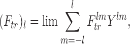 |
2.12 |
where the limit is taken in the direction of the particle’s position. The charge can be placed on the axis θ = 0, and this choice produces an axisymmetric field with contributions from m = 0 only. Because Yl0 = [(2l + 1)/4π ]1/2Pl (cosθ) and Pl (1) = 1, we have
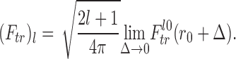 |
2.13 |
The sign of Δ is arbitrary, and (Ftr)l depends on the direction in which r0 is approached.
The charge density of a static particle can also be decomposed in spherical harmonics, and the mode coefficients are given by
 |
2.14 |
where f0 = (1 − M/r0)2. If we let
 |
2.15 |
then Gauss’s law in the extreme Reissner-Nordström spacetime can be shown to reduce to
 |
2.16 |
in which a prime indicates differentiation with respect to r, and the index l on Φ is omitted to simplify the expressions. The solution to Eq. (2.16) can be expressed as Φ(r) = Φ>(r)Θ(r − r0) + Φ<(r)Θ(r0 − r), where Φ> and Φ< are each required to satisfy the homogeneous equation (f Φ′)′ − l (l + 1)Φ/r2 = 0, as well as the junction conditions
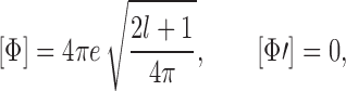 |
2.17 |
with [Φ]:= Φ>(r0) − Φ<(r0) denoting the jump across r = r0.
For l = 0 the general solution to the homogeneous equation is c1r* + c2, where c1 and c2 are constants and r * = ∫ f−1 dr. The solution for r < r0 must be regular at r = M, and we select Φ< = constant. The solution for r > r0 must produce a field that decays as r−2 at large r, and we again select Φ> = constant. Since each constant is proportional to the total charge enclosed within a sphere of radius r, we arrive at
 |
2.18 |
for l ≠ 0 the solutions to the homogeneous equation are
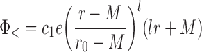 |
2.19 |
and
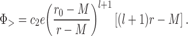 |
2.20 |
The constants c1 and c2 are determined by the junction conditions, and we get
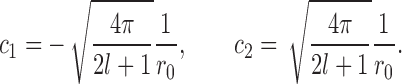 |
2.21 |
The modes of the electromagnetic field are now completely determined.
According to the foregoing results, and recalling the definition of Eq. (2.13), the multipole coefficients of the electromagnetic field at r = r0 + 0+ are given by
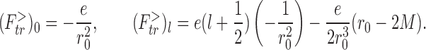 |
2.22 |
for r = r0 + 0− we have instead
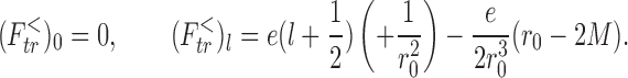 |
2.23 |
We observe that the multipole coefficients lead to a diverging mode sum. We also observe, however, that the multipole structure is identical to the decomposition of the singular field displayed in Eq. (2.8). Comparison of the two expressions allows us to determine the regularization parameters for the given situation, and we obtain
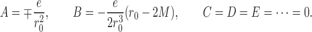 |
2.24 |
Regularization of the mode sum via Eq. (2.9) reveals that the modes l ≠ 0 give rise to the singular field, while the regular field comes entirely from the mode l = 0. In this case, therefore, we can state that the exact expression for the regular field evaluated at the position of the particle is 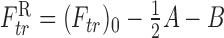 , or
, or 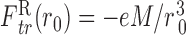 . Because the regular field must be a solution to the vacuum Maxwell equations, its monopole structure guarantees that its value at any position is given by
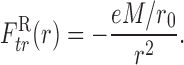 |
2.25 |
This is the field of an image charge e′ = +eM/r0 situated at the centre of the black hole.
The self-force acting on the static charge is then
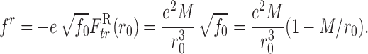 |
2.26 |
This expression agrees with the Smith-Will force of Eq. (1.50). The interpretation of the result in terms of an interaction between e and the image charge e′ was elaborated in Sec. 1.10.
Computations in Schwarzschild spacetime
The mode-sum method was successfully implemented in Schwarzschild spacetime to compute the scalar and electromagnetic self-forces on a static particle [31, 36]. It was used to calculate the scalar self-force on a particle moving on a radial trajectory [10], circular orbit [30, 51, 87, 37], and a generic bound orbit [84]. It was also developed to compute the electromagnetic self-force on a particle moving on a generic bound orbit [85], as well as the gravitational self-force on a point mass moving on circular [21, 1] and eccentric orbits [22]. The mode-sum method was also used to compute unambiguous physical effects associated with the gravitational self-force [50, 157, 11], and these results were involved in detailed comparisons with post-Newtonian theory [50, 29, 28, 44, 11]. These achievements will be described in more detail in Section 2.6.
An issue that arises in computations of the electromagnetic and gravitational self-forces is the choice of gauge. While the self-force formalism is solidly grounded in the Lorenz gauge (which allows the formulation of a wave equation for the potentials, the decomposition of the retarded field into singular and regular pieces, and the computation of regularization parameters), it is often convenient to carry out the numerical computations in other gauges, such as the popular Regge-Wheeler gauge and the Chrzanowski radiation gauge described below. Compatibility of calculations carried out in different gauges has been debated in the literature. It is clear that the singular field is gauge invariant when the transformation between the Lorenz gauge and the adopted gauge is smooth on the particle’s world line; in such cases the regularization parameters also are gauge invariant [17], the transformation affects the regular field only, and the self-force changes according to Eq. (1.49). The transformations between the Lorenz gauge and the Regge-Wheeler and radiation gauges are not regular on the world line, however, and in such cases the regularization of the retarded field must be handled with extreme care.
Computations in Kerr spacetime; metric reconstruction
The reliance of the mode-sum method on a spherical-harmonic decomposition makes it generally impractical to apply to self-force computations in Kerr spacetime. Wave equations in this spacetime are better analyzed in terms of a spheroidal-harmonic decomposition, which simultaneously requires a Fourier decomposition of the field’s time dependence. (The eigenvalue equation for the angular functions depends on the mode’s frequency.) For a static particle, however, the situation simplifies, and Burko and Liu [35] were able to apply the method to calculate the self-force on a static scalar charge in Kerr spacetime. More recently, Warburton and Barack [181] carried out a mode-sum calculations of the scalar self-force on a particle moving on equatorial orbits of a Kerr black hole. They first solve for the spheroidal multipoles of the retarded potential, and then re-express them in terms of spherical-harmonic multipoles. Fortunately, they find that a spheroidal multipole is well represented by summing over a limited number of spherical multipoles. The Warburton-Barack work represents the first successful computations of the self-force in Kerr spacetime, and it reveals the interesting effect of the black hole’s spin on the behaviour of the self-force.
The analysis of the scalar wave equation in terms of spheroidal functions and a Fourier decomposition permits a complete separation of the variables. For decoupling and separation to occur in the case of a gravitational perturbation, it is necessary to formulate the perturbation equations in terms of Newman-Penrose (NP) quantities [172], and to work with the Teukolsky equation that governs their behaviour. Several computer codes are now available that are capable of integrating the Teukolsky equation when the source is a point mass moving on an arbitrary geodesic of the Kerr spacetime. (A survey of these codes is given below.) Once a solution to the Teukolsky equation is at hand, however, there still remains the additional task of recovering the metric perturbation from this solution, a problem referred to as metric reconstruction.
Reconstruction of the metric perturbation from solutions to the Teukolsky equation was tackled in the past in the pioneering efforts of Chrzanowski [41], Cohen and Kegeles [42, 105], Stewart [166], and Wald [179]. These works have established a procedure, typically attributed to Chrzanowski, that returns the metric perturbation in a so-called radiation gauge. An important limitation of this method, however, is that it applies only to vacuum solutions to the Teukolsky equation. This makes the standard Chrzanowski procedure inapplicable in the self-force context, because a point particle must necessarily act as a source of the perturbation. Some methods were devised to extend the Chrzanowski procedure to accommodate point sources in specific circumstances [121, 134], but these were not developed sufficiently to permit the computation of a self-force. See Ref. [184] for a review of metric reconstruction from the perspective of self-force calculations.
A remarkable breakthrough in the application of metric-reconstruction methods in self-force calculations was achieved by Keidl, Wiseman, and Friedman [107, 106, 108], who were able to compute a self-force starting from a Teukolsky equation sourced by a point particle. They did it first for the case of an electric charge and a point mass held at a fixed position in a Schwarzschild space-time [107], and then for the case of a point mass moving on a circular orbit around a Schwarzschild black hole [108]. The key conceptual advance is the realization that, according to the Detweiler-Whiting perspective, the self-force is produced by a regularized field that satisfies vacuum field equations in a neighbourhood of the particle. The regular field can therefore be submitted to the Chrzanowski procedure and reconstructed from a source-free solution to the Teukolsky equation.
More concretely, suppose that we have access to the Weyl scalar ψ0 produced by a point mass moving on a geodesic of a Kerr spacetime. To compute the self-force from this, one first calculates the singular Weyl scalar  from the Detweiler-Whiting singular field
  , and subtracts it from ψ0. The result is a regularized Weyl scalar
  , which is a solution to the homogeneous Teukolsky equation. This sets the stage for the metric-reconstruction procedure, which returns (a piece of) the regular field
  in the radiation gauge selected by Chrzanowski. The computation must be completed by adding the pieces of the metric perturbation that are not contained in ψ0; these are referred to either as the nonradiative degrees of freedom (since ψ0 is purely radiative), or as the l = 0 and l = 1 field multipoles (because the sum over multipoles that make up ψ0 begins at l = 2). A method to complete the Chrzanowski reconstruction of
  was devised by Keidl et al. [107, 108], and the end result leads directly to the gravitational self-force. The relevance of the l = 0 and l = 1 modes to the gravitational self-force was emphasized by Detweiler and Poisson [52].
Time-domain versus frequency-domain methods
When calculating the spherical-harmonic components Φlm (t, r) of the retarded potential Φ — refer back to Eq. (2.6) — one can choose to work either directly in the time domain, or perform a Fourier decomposition of the time dependence and work instead in the frequency domain. While the time-domain method requires the integration of a partial differential equation in t and r, the frequency-domain method gives rise to set of ordinary differential equations in r, one for each frequency ω. For particles moving on circular or slightly eccentric orbits in Schwarzschild spacetime, the frequency spectrum is limited to a small number of discrete frequencies, and a frequency-domain method is easy to implement and yields highly accurate results. As the orbital eccentricity increases, however, the frequency spectrum broadens, and the computational burden of summing over all frequency components becomes more significant. Frequency-domain methods are less efficient for large eccentricities, the case of most relevance for extreme-mass-ratio inspirals, and it becomes advantageous to replace them with time-domain methods. (See Ref. [25] for a quantitative study of this claim.) This observation has motivated the development of accurate evolution codes for wave equations in 1+1 dimensions.
Such codes must be able to accommodate point-particle sources, and various strategies have been pursued to represent a Dirac distribution on a numerical grid, including the use of very narrow Gaussian pulses [116, 110, 34] and of “finite impulse representations” [168]. These methods do a good job with waveform and radiative flux calculations far away from the particle, but are of very limited accuracy when computing the potential in a neighborhood of the particle. A numerical method designed to provide an exact representation of a Dirac distribution in a time-domain computation was devised by Lousto and Price [120] (see also Ref. [123]). It was implemented by Haas [84, 85] for the specific purpose of evaluating Φlm (t, r) at the position of particle and computing the self-force. Similar codes were developed by other workers for scalar [176] and gravitational [21, 22] self-force calculations.
Most extant time-domain codes are based on finite-difference techniques, but codes based on pseudo-spectral methods have also been developed [67, 68, 37, 38]. Spectral codes are a powerful alternative to finite-difference codes, especially when dealing with smooth functions, because they produce much faster convergence. The fact that self-force calculations deal with point sources and field modes that are not differentiable might suggest that spectral convergence should not be expected in this case. This objection can be countered, however, by placing the particle at the boundary between two spectral domains. Functions are then smooth in each domain, and discontinuities are handled by formulating appropriate boundary conditions; spectral convergence is thereby achieved.
Effective-source method
The mode-sum methods reviewed in the preceding subsection have been developed and applied extensively, but they do not exhaust the range of approaches that may be exploited to compute a self-force. Another set of methods, devised by Barack and his collaborators [12, 13, 60] as well as Vega and his collaborators [176, 177, 175], begin by recognizing that an approximation to the exact singular potential can be used to regularize the delta-function source term of the original field equation. We shall explain this idea in the simple context of a scalar potential Φ.
We continue to write the wave equation for the retarded potential Φ in the schematic form
 |
2.27 |
where □ is the wave operator in curved spacetime, and δ (x, z) is a distributional source term that depends on the particle’s world line γ through its coordinate representation z (τ). By construction, the exact singular potential ΦS satisfies the same equation, and an approximation to the singular potential, denoted  , will generally satisfy an equation of the form
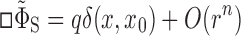 |
2.28 |
for some integer n > 0, where r is a measure of distance to the world line. A “better” approximation to the singular potential is one with a higher value of n. From the approximated singular potential we form an approximation to the regular potential by writing
 |
2.29 |
where W is a window function whose properties will be specified below. The approximated regular potential is governed by the wave equation
 |
2.30 |
and the right-hand side of this equation defines the effective source term S (x, z). This equation is much less singular than Eq. (2.27), and it can be integrated using numerical methods designed to handle smooth functions.
To see this, we write the effective source more specifically as
 |
2.31 |
With the window function W designed to approach unity as x → z, we find that the delta function that arises from the third term on the right-hand side precisely cancels out the fourth term. To keep the other terms in S well behaved on the world line, we further restrict the window function to satisfy ∇αW = O (rp) with p ≥ 2; this ensures that multiplication by 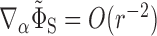 leaves behind a bounded quantity. In addition, we demand that □W = O (rq) with q ≥ 1, so that multiplication by
  again produces a bounded quantity. It is also useful to require that W (x) have compact (spatial) support, to ensure that the effective source term S (x, z) does not extend beyond a reasonably small neighbourhood of the world line; this property also has the virtue of making
  precisely equal to the retarded potential Φ outside the support of the window function. This implies, in particular, that
  can be used directly to compute radiative fluxes at infinity. Another considerable virtue of these specifications for the window function is that they guarantee that the gradient of
  is directly tied to the self-force. We indeed see that
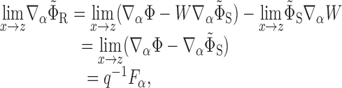 |
2.32 |
with the second line following by virtue of the imposed conditions on W, and the third line from the properties of the approximated singular field.
The effective-source method therefore consists of integrating the wave equation
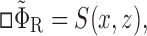 |
2.33 |
for the approximated regular potential  , with a source term S (x, z) that has become a regular function (of limited differentiability) of the spacetime coordinates x. The method is also known as a “puncture approach,” in reference to a similar regularization strategy employed in numerical relativity. It is well suited to a 3+1 integration of the wave equation, which can be implemented on mature codes already in circulation within the numerical-relativity community. An important advantage of a 3+1 implementation is that it is largely indifferent to the choice of background spacetime, and largely insensitive to the symmetries possessed by this spacetime; a self-force in Kerr spacetime is in principle just as easy to obtain as a self-force in Schwarzschild spacetime.
The method is also well suited to a self-consistent implementation of the self-force, in which the motion of the particle is not fixed in advance, but determined by the action of the computed self-force. This amounts to combining Eq. (2.33) with the self-force equation
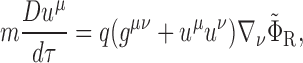 |
2.34 |
in which the field is evaluated on the dynamically determined world line. The system of equations is integrated jointly, and self-consistently. The 3+1 version of the effective-source approach presents a unique opportunity for the numerical-relativity community to get involved in self-force computations, with only a minimal amount of infrastructure development. This was advocated by Vega and Detweiler [176], who first demonstrated the viability of the approach with a 1+1 time-domain code for a scalar charge on a circular orbit around a Schwarzschild black hole. An implementation with two separate 3+1 codes imported from numerical relativity was also accomplished [177].
The work of Barack and collaborators [12, 13] is a particular implementation of the effective-source approach in a 2+1 numerical calculation of the scalar self-force in Kerr spacetime. (See also the independent implementation by Lousto and Nakano [119].) Instead of starting with Eq. (2.27), they first decompose Φ according to
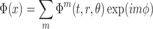 |
2.35 |
and formulate reduced wave equations for the Fourier coefficients Φm. Each coefficient is then regularized with an appropriate singular field  , which eliminates the delta-function from Eq. (2.27). This gives rise to regularized source terms for the reduced wave equations, which can then be integrated with a 2+1 evolution code. In the final stage of the computation, the self-force is recovered by summing over the regularized Fourier coefficients. This strategy, known as the m-mode regularization scheme, is currently under active development. Recently it was successfully applied by Dolan and Barack [60] to compute the self-force on a scalar charge in circular orbit around a Schwarzschild black hole.
Quasilocal approach with “matched expansions”
As was seen in Eqs. (1.33), (1.40), and (1.47), the self-force can be expressed as an integral over the past world line of the particle, the integrand involving the Green’s function for the appropriate wave equation. Attempts have been made to compute the Green’s function directly [132, 141, 33, 86], and to evaluate the world-line integral. The quasilocal approach, first introduced by Anderson and his collaborators [4, 3, 6, 5], is based on the expectation that the world-line integral might be dominated by the particle’s recent past, so that the Green’s function can be represented by its Hadamard expansion, which is restricted to the normal convex neighbourhood of the particle’s current position. To help with this enterprise, Ottewill and his collaborators [136, 182, 137, 39] have pushed the Hadamard expansion to a very high order of accuracy, building on earlier work by Décanini and Folacci [48].
The weak-field calculations performed by DeWitt and DeWitt [132] and Pfenning and Poisson [141] suggest that the world-line integral is not, in fact, dominated by the recent past. Instead, most of the self-force is produced by signals that leave the particle at some time in the past, scatter off the central mass, and reconnect with the particle at the current time; such signals mark the boundary of the normal convex neighbourhood. The quasilocal evaluation of the world-line integral must therefore be supplemented with contributions from the distant past, and this requires a representation of the Green’s function that is not limited to the normal convex neighbourhood. In some spacetimes it is possible to express the Green’s function as an expansion in quasi-normal modes, as was demonstrated by Casals and his collaborators for a static scalar charge in the Nariai spacetime [40]. Their study provided significant insights into the geometrical structure of Green’s functions in curved spacetime, and increased our understanding of the non-local character of the self-force.
Adiabatic approximations
The accurate computation of long-term waveforms from extreme-mass-ratio inspirals (EMRIs) involves a lengthy sequence of calculations that include the calculation of the self-force. One can already imagine the difficulty of numerically integrating the coupled linearized Einstein equation for durations much longer than has ever been attempted by existing numerical codes. While doing so, the code would also have to evaluate the self-force reasonably often (if not at each time step) in order to remain close to the true dynamics of the point mass. Moreover, gravitational-wave data analysis via matched filtering require full evolutions of the sort just described for a large sample of systems parameters. All these considerations underlie the desire for simplified approximations to fully self-consistent self-force EMRI models.
The adiabatic approximation refers to one such class of potentially useful approximations. The basic assumption is that the secular effects of the self-force occur on a timescale that is much longer than the orbital period. In an extreme-mass-ratio binary, this assumption is valid during the early stage of inspiral; it breaks down in the final moments, when the orbit transitions to a quasi-radial infall called the plunge. From the adiabaticity assumption, numerous approximations have been formulated: For example, (i) since the particle’s orbit deviates only slowly from geodesic motion, the self-force can be calculated from a field sourced by a geodesic; (ii) since the radiation-reaction timescale trr, over which a significant shrinking of the orbit occurs due to the self-force, is much longer than the orbital period, periodic effects of the self-force can be neglected; and (iii) conservative effects of the self-force can be neglected (the radiative approximation).
A seminal example of an adiabatic approximation is the Peters-Mathews formalism [140, 139], which determines the long-term evolution of a binary orbit by equating the time-averaged rate of change of the orbital energy E and angular momentum L to, respectively, the flux of gravitational-wave energy and angular momentum at infinity. This formalism was used to successfully predict the decreasing orbital period of the Hulse-Taylor pulsar, before more sophisticated methods, based on post-Newtonian equations of motion expanded to 2.5pn order, were incorporated in times-of-arrival formulae.
In the hope of achieving similar success in the context of the self-force, considerable work has been done to formulate a similar approximation for the case of an extreme-mass-ratio inspiral [124, 125, 126, 98, 61, 62, 159, 158, 78, 128, 94]. Bound geodesics in Kerr spacetime are specified by three constants of motion — the energy E, angular momentum L, and Carter constant C. If one could easily calculate the rates of change of these quantities, using a method analogous to the Peters-Mathews formalism, then one could determine an approximation to the long-term orbital evolution of the small body in an EMRI, avoiding the lengthy process of regularization involved in the direct integration of the self-forced equation of motion. In the early 1980s, Gal’tsov [77] showed that the average rates of change of E and L, as calculated from balance equations that assume geodesic source motion, agree with the averaged rates of change induced by a self-force constructed from a radiative Green’s function defined as  . As discussed in Section 1.4, this is equal to the regular two-point function Gr in flat spacetime, but Grad ≠ GR in curved spacetime; because of its time-asymmetry, it is purely dissipative. Mino [124], building on the work of Gal’tsov, was able to show that the true self-force and the dissipative force constructed from Grad cause the same averaged rates of change of all three constants of motion, lending credence to the radiative approximation. Since then, the radiative Green’s function was used to derive explicit expressions for the rates of change of E, L, and C in terms of the particle’s orbit and wave amplitudes at infinity [159, 158, 78], and radiative approximations based on such expressions have been concretely implemented by Drasco, Hughes and their collaborators [99, 61, 62].
The relevance of the conservative part of the self-force — the part left out when using Grad — was analyzed in numerous recent publications [32, 148, 146, 147, 94, 97]. As was shown by Pound et al. [148, 146, 147], neglect of the conservative effects of the self-force generically leads to long-term errors in the phase of an orbit and the gravitational wave it produces. These phasing errors are due to orbital precession and a direct shift in orbital frequency. This shift can be understood by considering a conservative force acting on a circular orbit: the force is radial, it alters the centripetal acceleration, and the frequency associated with a given orbital radius is affected. Despite these errors, a radiative approximation may still suffice for gravitational-wave detection [94]; for circular orbits, which have minimal conservative effects, radiative approximations may suffice even for parameter-estimation [97]. However, at this point in time, these analyses remain inconclusive because they all rely on extrapolations from post-Newtonian results for the conservative part of the self-force. For a more comprehensive discussion of these issues, the reader is referred to Ref. [94, 143].
Hinderer and Flanagan performed the most comprehensive study of these issues [69], utilizing a two-timescale expansion [109, 145] of the field equations and self-forced equations of motion in an EMRI. In this method, all dynamical variables are written in terms of two time coordinates: a fast time t and a slow time  . In the case of an EMRI, the dynamical variables are the metric and the phase-space variables of the world line. The fast-time dependence captures evolution on the orbital timescale ∼ M, while the slow-time dependence captures evolution on the radiation-reaction timescale ∼ M2/m. One obtains a sequence of fast-time and slow-time equations by expanding the full equations in the limit of small m while treating the two time coordinates as independent. Solving the leading-order fast-time equation, in which
  is held fixed, yields a metric perturbation sourced by a geodesic, as one would expect from the linearized field equations for a point particle. The leading-order effects of the self-force are incorporated by solving the slow-time equation and letting
  vary. (Solving the next-higher-order slow-time equation determines similar effects, but also the backreaction that causes the parameters of the large black hole to change slowly.)
Using this method, Hinderer and Flanagan identified the effects of the various pieces of the self-force. To describe this we write the self-force as
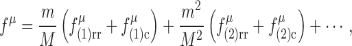 |
2.36 |
where ‘rr’ denotes a radiation-reaction, or dissipative, piece of the force, and ‘c’ denotes a conservative piece. Hinderer and Flanagan’s principal result is a formula for the orbital phase (which directly determines the phase of the emitted gravitational waves) in terms of these quantities:
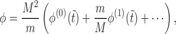 |
2.37 |
where ϕ(0) depends on an averaged piece of  , while ϕ(1) depends on
  , the oscillatory piece of
  , and the averaged piece of
  . From this result, we see that the radiative approximation yields the leading-order phase, but fails to determine the first subleading correction. We also see that the approximations (i)–(iii) mentioned above are consistent (so long as the parameters of the ‘geodesic’ source are allowed to vary slowly) at leading order in the two-timescale expansion, but diverge from one another beyond that order. Hence, we see that an adiabatic approximation is generically insufficient to extract parameters from a waveform, since doing so requires a description of the inspiral accurate up to small (i.e., smaller than order-1) errors. But we also see that an adiabatic approximation based on the radiative Green’s function may be an excellent approximation for other purposes, such as detection.
To understand this result, consider the following naive analysis of a quasicircular EMRI — that is, an orbit that would be circular were it not for the action of the self-force, and which is slowly spiraling into the large central body. We write the orbital frequency as  , where ω(0)(E) is the frequency as a function of energy on a circular geodesic, and
  is the correction to this due to the conservative part of the first-order self-force (part of the correction also arises due to oscillatory zeroth-order effects combining with oscillatory first-order effects, but for simplicity we ignore this contribution). Neglecting oscillatory effects, we write the energy in terms only of its slow-time dependence:
  . The leading-order term E(0) is determined by the dissipative part of first-order self-force, while E(1) is determined by both the dissipative part of the second-order force and a combination of conservative and dissipative parts of the first-order force. Substituting this into the frequency, we arrive at
 |
2.38 |
where  , in which the partial derivative is evaluated at E = E(0) Integrating this over a radiation-reaction time, we arrive at the orbital phase of Eq. (2.37). (In a complete description, E (t) will have oscillatory pieces, which are functions of t rather than
  , and one must know these in order to correctly determine ϕ(1).) Such a result remains valid even for generic orbits, where, for example, orbital precession due to the conservative force contributes to the analogue of
Physical consequences of the self-force
To be of relevance to gravitational-wave astronomy, the paramount goal of the self-force community remains the computation of waveforms that properly encode the long-term dynamical evolution of an extreme-mass-ratio binary. This requires a fully consistent orbital evolution fed to a wave-generation formalism, and to this day the completion of this program remains as a future challenge. In the meantime, a somewhat less ambitious, though no less compelling, undertaking is that of probing the physical consequences of the self-force on the motion of point particles.
Scalar charge in cosmological spacetimes
The intriguing phenomenon of a scalar charge changing its rest mass because of an interaction with its self-field was studied by Burko, Harte, and Poisson [33] and Haas and Poisson [86] in the simple context of a particle at rest in an expanding universe. The scalar Green’s function could be computed explicitly for a wide class of cosmological spacetimes, and the action of the field on the particle determined without approximations. It is found that for certain cosmological models, the mass decreases and then increases back to its original value. For other models, the mass is restored only to a fraction of its original value. For de Sitter spacetime, the particle radiates all of its rest mass into monopole scalar waves.
Physical consequences of the gravitational self-force
The earliest calculation of a gravitational self-force was performed by Barack and Lousto for the case of a point mass plunging radially into a Schwarzschild black hole [14]. The calculation, however, depended on a specific choice of gauge and did not identify unambiguous physical consequences of the self-force. To obtain such consequences, it is necessary to combine the self-force (computed in whatever gauge) with the metric perturbation (computed in the same gauge) in the calculation of a well-defined observable that could in principle be measured. For example, the conservative pieces of the self-force and metric perturbation can be combined to calculate the shifts in orbital frequencies that originate from the gravitational effects of the small body; an application of such a calculation would be to determine the shift (as measured by frequency) in the innermost stable circular orbit of an extreme-mass-ratio binary, or the shift in the rate of periastron advance for eccentric orbits. Such calculations, however, must exclude all dissipative aspects of the self-force, because these introduce an inherent ambiguity in the determination of orbital frequencies.
A calculation of this kind was recently achieved by Barack and Sago [22, 23], who computed the shift in the innermost stable circular orbit of a Schwarzschild black hole caused by the conservative piece of the gravitational self-force. The shift in orbital radius is gauge dependent (and was reported in the Lorenz gauge by Barack and Sago), but the shift in orbital frequency is measurable and therefore gauge invariant. Their main result — a genuine milestone in self-force computations — is that the fractional shift in frequency is equal to 0.4870m/M; the frequency is driven upward by the gravitational self-force. Barack and Sago compare this shift to the ambiguity created by the dissipative piece of the self-force, which was previously investigated by Ori and Thorne [135] and Sundararajan [167]; they find that the conservative shift is very small compared with the dissipative ambiguity. In a follow-up analysis, Barack, Damour, and Sago [11] computed the conservative shift in the rate of periastron advance of slightly eccentric orbits in Schwarzschild spacetime.
Conservative shifts in the innermost stable circular orbit of a Schwarzschild black hole were first obtained in the context of the scalar self-force by Diaz-Rivera et al. [55]; in this case they obtain a fractional shift of 0.0291657q2/(mM), and here also the frequency is driven upward.
Detweiler’s redshift factor
In another effort to extract physical consequences from the gravitational self-force on a particle in circular motion in Schwarzschild spacetime, Detweiler discovered [50] that ut, the time component of the velocity vector in Schwarzschild coordinates, is invariant with respect to a class of gauge transformations that preserve the helical symmetry of the perturbed spacetime. Detweiler further showed that 1/ut is an observable: it is the redshift that a photon suffers when it propagates from the orbiting body to an observer situated at a large distance on the orbital axis. This gaugeinvariant quantity can be calculated together with the orbital frequency Ω, which is a second gaugeinvariant quantity that can be constructed for circular orbits in Schwarzschild spacetime. Both ut and Ω acquire corrections of fractional order m/M from the self-force and the metric perturbation. While the functions ut (r) and Ω(r) are still gauge dependent, because of the dependence on the radial coordinate r, elimination of r from these relations permits the construction of ut (Ω), which is gauge invariant. A plot of ut as a function of Ω therefore contains physically unambiguous information about the gravitational self-force.
The computation of the gauge-invariant relation ut(Ω) opened the door to a detailed comparison between the predictions of the self-force formalism to those of post-Newtonian theory. This was first pursued by Detweiler [50], who compared ut (Ω) as determined accurately through second post-Newtonian order, to self-force results obtained numerically; he reported full consistency at the expected level of accuracy. This comparison was pushed to the third post-Newtonian order [29, 28, 44, 11]. Agreement is remarkable, and it conveys a rather deep point about the methods of calculation. The computation of ut(Ω), in the context of both the self-force and post-Newtonian theory, requires regularization of the metric perturbation created by the point mass. In the self-force calculation, removal of the singular field is achieved with the Detweiler-Whiting prescription, while in post-Newtonian theory it is performed with a very different prescription based on dimensional regularization. Each prescription could have returned a different regularized field, and therefore a different expression for ut(Ω). This, remarkably, does not happen; the singular fields are “physically the same” in the self-force and post-Newtonian calculations.
A generalization of Detweiler’s redshift invariant to eccentric orbits was recently proposed and computed by Barack and Sago [24], who report consistency with corresponding post-Newtonian results in the weak-field regime. They also computed the influence of the conservative gravitational self-force on the periastron advance of slightly eccentric orbits, and compared their results with full numerical relativity simulations for modest mass-ratio binaries. Thus, in spite of the unavailability of self-consistent waveforms, it is becoming clear that self-force calculations are already proving to be of value: they inform post-Newtonian calculations and serve as benchmarks for numerical relativity.
Part I: General Theory of Bitensors
Synge’s world function
Definition
In this and the following sections we will construct a number of bitensors, tensorial functions of two points in spacetime. The first is x′, which we call the “base point”, and to which we assign indices α′, β′, etc. The second is x, which we call the “field point”, and to which we assign indices α, β, etc. We assume that x belongs to N (x′), the normal convex neighbourhood of x′; this is the set of points that are linked to x′ by a unique geodesic. The geodesic segment β that links x to x′ is described by relations zμ (λ) in which λ is an affine parameter that ranges from λ0 to λ1; we have z (λ0):= x′ and z (λ1):= x. To an arbitrary point z on the geodesic we assign indices μ, ν, etc. The vector tμ = dzμ/dλ is tangent to the geodesic, and it obeys the geodesic equation Dtμ/dλ = 0. The situation is illustrated in Figure 5.
Figure 5.

The base point x′, the field point x, and the geodesic segment β that links them. The geodesic is described by parametric relations zμ (λ) and tμ = dzμ/dλ is its tangent vector.
Synge’s world function is a scalar function of the base point x′ and the field point x. It is defined by
 |
3.1 |
and the integral is evaluated on the geodesic β that links x to x′. You may notice that σ is invariant under a constant rescaling of the affine parameter,  , where a and b are constants.
By virtue of the geodesic equation, the quantity ε: = gμνtμtν is constant on the geodesic. The world function is therefore numerically equal to  . If the geodesic is timelike, then λ can be set equal to the proper time τ, which implies that ε = −1 and
  . If the geodesic is spacelike, then λ can be set equal to the proper distance s, which implies that ε = 1 and
  . If the geodesic is null, then σ = 0. Quite generally, therefore, the world function is half the squared geodesic distance between the points x′ and x.
In flat spacetime, the geodesic linking x to x′ is a straight line, and  in Lorentzian coordinates.
Differentiation of the world function
The world function σ (x, x′) can be differentiated with respect to either argument. We let σα = ∂σ/∂xα be its partial derivative with respect to x, and σα′ = ∂σ/∂xα′ its partial derivative with respect to x′. It is clear that σα behaves as a dual vector with respect to tensorial operations carried out at x, but as a scalar with respect to operations carried out x′. Similarly, σα′ is a scalar at x but a dual vector at x′.
We let σαβ:= ∇βσα be the covariant derivative of σα with respect to x; this is a rank-2 tensor at x and a scalar at x′. Because σ is a scalar at x, we have that this tensor is symmetric: σβα = σαβ. Similarly, we let σαβ′ := ∂β′σα = ∂2σ/∂xβ′ ∂xα be the partial derivative of σα with respect to x′; this is a dual vector both at x and x′. We can also define σα′β := ∂βσα ′ = ∂2σ/∂xβ∂xα′ to be the partial derivative of σα′ with respect to x. Because partial derivatives commute, these bitensors are equal: σβ′α = σαβ ′. Finally, we let σσα′β := ∇β′σα′ be the covariant derivative of σα′ with respect to x′; this is a symmetric rank-2 tensor at x′ and a scalar at x.
The notation is easily extended to any number of derivatives. For example, we let σσαβγ′:= ∇δ′∇γ∇β ∇ασ, which is a rank-3 tensor at x and a dual vector at x′. This bitensor is symmetric in the pair of indices α and β, but not in the pairs α and γ, nor β and γ. Because ∇δ′ is here an ordinary partial derivative with respect to x′, the bitensor is symmetric in any pair of indices involving δ′. The ordering of the primed index relative to the unprimed indices is therefore irrelevant: the same bitensor can be written as σδ′αβγ or σαδ′βγ or σαβδ′γ, making sure that the ordering of the unprimed indices is not altered.
More generally, we can show that derivatives of any bitensor Ω…(x,x′) satisfy the property
 |
3.2 |
in which “⋯” stands for any combination of primed and unprimed indices. We start by establishing the symmetry of Ω…;αβ′ with respect to the pair α and β′. This is most easily done by adopting Fermi normal coordinates (see Section 9) adapted to the geodesic β and setting the connection to zero both at x and x′. In these coordinates, the bitensor Ω…;α is the partial derivative of Ω… with respect to xα, and Ω…;αβ′ is obtained by taking an additional partial derivative with respect to xβ′. These two operations commute, and Ω…;β′ α = Ω…;αβ′ follows as a bitensorial identity. Equation (3.2) then follows by further differentiation with respect to either x or x′.
The message of Eq. (3.2), when applied to derivatives of the world function, is that while the ordering of the primed and unprimed indices relative to themselves is important, their ordering with respect to each other is arbitrary. For example, σα′β′γδ′δ = σα′β′δ′γδ = σγϵα′β′δ′.
Evaluation of first derivatives
We can compute σα by examining how σ varies when the field point x moves. We let the new field point be x + δx, and δσ:= σ (x + δx, x′) − σ (x, x′) is the corresponding variation of the world function. We let β + δβ be the unique geodesic segment that links x + δx to x′; it is described by relations zμ (λ) + δzμ (λ), in which the affine parameter is scaled in such a way that it runs from λ0 to λ1 also on the new geodesic. We note that δz (λ0) = δx′ = 0 and δz (λ1) = δx.
Working to first order in the variations, Eq. (3.1) implies
 |
where Δλ = λ1 − λ0, an overdot indicates differentiation with respect to λ, and the metric and its derivatives are evaluated on β. Integrating the first term by parts gives
 |
The integral vanishes because zμ (λ) satisfies the geodesic equation. The boundary term at λ0 is zero because the variation δzμ vanishes there. We are left with δσ = Δλgαβtα δxβ, or
 |
3.3 |
in which the metric and the tangent vector are both evaluated at x. Apart from a factor Δλ, we see that σα (x, x′) is equal to the geodesic’s tangent vector at x. If in Eq. (3.3) we replace x by a generic point z (λ) on β, and if we correspondingly replace λ1 by λ, we obtain σμ (z, x′) = (λ − λ0)tμ; we therefore see that σμ (z, x′) is a rescaled tangent vector on the geodesic.
A virtually identical calculation reveals how σ varies under a change of base point x′. Here the variation of the geodesic is such that δz (λ0) = δx′ and δz (λ1) = δx = 0, and we obtain δσ = −Δλgα′β′tα′ δxβ′. This shows that
 |
3.4 |
in which the metric and the tangent vector are both evaluated at x′. Apart from a factor Δλ, we see that σα′ (x, x′) is minus the geodesic’s tangent vector at x′.
It is interesting to compute the norm of σα. According to Eq. (3.3) we have  . According to Eq. (3.1), this is equal to 2σ. We have obtained
 |
3.5 |
and similarly,
 |
3.6 |
These important relations will be the starting point of many computations to be described below.
We note that in flat spacetime, σα = ηαβ (x − x′)β and σα′ = −ηαβ (x − x′)β in Lorentzian coordinates. From this it follows that σαβ = σα′β′ = −σαβ′ = −σα′β = ηαβ, and finally, gαβσαβ = 4 = ga′β′σa′β′.
Congruence of geodesics emanating from x′
If the base point x′ is kept fixed, σ can be considered to be an ordinary scalar function of x. According to Eq. (3.5), this function is a solution to the nonlinear differential equation  . Suppose that we are presented with such a scalar field. What can we say about it?
An additional differentiation of the defining equation reveals that the vector σα := σ;α satisfies
 |
3.7 |
which is the geodesic equation in a non-affine parameterization. The vector field is therefore tangent to a congruence of geodesics. The geodesics are timelike where σ < 0, they are spacelike where σ > 0, and they are null where σ = 0. Here, for concreteness, we shall consider only the timelike subset of the congruence.
The vector
 |
3.8 |
is a normalized tangent vector that satisfies the geodesic equation in affine-parameter form: uα ;βuβ = 0. The parameter λ is then proper time τ. If λ* denotes the original parameterization of the geodesics, we have that dλ*/dτ = |2σ |−1/2, and we see that the original parameterization is singular at σ = 0.
In the affine parameterization, the expansion of the congruence is calculated to be
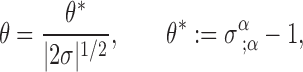 |
3.9 |
where θ* = (δV)−1(d/dλ*)(δV) is the expansion in the original parameterization (δV is the congruence’s cross-sectional volume). While θ* is well behaved in the limit σ → 0 (we shall see below that θ* → 3), we have that θ → ∞. This means that the point x′ at which σ = 0 is a caustic of the congruence: all geodesics emanate from this point.
These considerations, which all follow from a postulated relation  , are clearly compatible with our preceding explicit construction of the world function.
Coincidence limits
It is useful to determine the limiting behaviour of the bitensors σ… as x approaches x′. We introduce the notation
 |
to designate the limit of any bitensor Ω…(x,x′) as x approaches x′; this is called the coincidence limit of the bitensor. We assume that the coincidence limit is a unique tensorial function of the base point x′, independent of the direction in which the limit is taken. In other words, if the limit is computed by letting λ → λ0 after evaluating Ω… (z, x′) as a function of λ on a specified geodesic β, it is assumed that the answer does not depend on the choice of geodesic.
Computation of coincidence limits
From Eqs. (3.1), (3.3), and (3.4) we already have
 |
4.1 |
Additional results are obtained by repeated differentiation of the relations (3.5) and (3.6). For example, Eq. (3.5) implies σγ = gαβσασβγ = σβσβγ, or (gβγ − σβγ)tβ = 0 after using Eq. (3.3). From the assumption stated in the preceding paragraph, σβγ becomes independent of tβ in the limit x → x′, and we arrive at [σαβ] = gα′β′. By very similar calculations we obtain all other coincidence limits for the second derivatives of the world function. The results are
 |
4.2 |
From these relations we infer that [ 4, so that [θ* ] = 3, where θ* was defined in Eq. (3.9).
To generate coincidence limits of bitensors involving primed indices, it is efficient to invoke Synge’s rule,
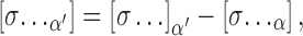 |
4.3 |
in which “⋯” designates any combination of primed and unprimed indices; this rule will be established below. For example, according to Synge’s rule we have [σαβ′] = [σα ];β′ − [σαβ ], and since the coincidence limit of σα is zero, this gives us [σαβ′] = − [σαβ] = −gα′β′, as was stated in Eq. (4.2). Similarly, [σα′β′] = [σα′];β′, − [σα′β] = − [σβα′] = ga′β′. The results of Eq. (4.2) can thus all be generated from the known result for [σαβ].
The coincidence limits of Eq. (4.2) were derived from the relation 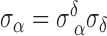 . We now differentiate this twice more and obtain
  . At coincidence we have
 |
or [σγαβ ] + [σβαγ ] = 0 if we recognize that the operations of raising or lowering indices and taking the limit x → x′ commute. Noting the symmetries of σαβ, this gives us 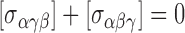 , or
, or  , or
, or  . Since the last factor is zero, we arrive at
 |
4.4 |
The last three results were derived from [σαβγ] = 0 by employing Synge’s rule. We now differentiate the relation  three times and obtain
 |
At coincidence this reduces to [σσαβγ ] + [σσαδβ ] + [σσαγβ ] =0. To simplify the third term we differentiate Ricci’s identity  with respect to xδ and then take the coincidence limit. This gives us [σσαγβ ] = [σσαβγ ] + Rα′δ′β′γ′. The same manipulations on the second term give [σαδβγ] = [σαβδγ]+ Rα′γ′β′δ′. Using the identity
  and the symmetries of the Riemann tensor, it is then easy to show that [σσαβδ ] = [σσαβγ ]. Gathering the results, we obtain 3[σσαβγ ] + Rα′γ′β′δ′ + Rα′δ′β′γ′ = 0, and Synge’s rule allows us to generalize this to any combination of primed and unprimed indices. Our final results are
 |
4.5 |
Derivation of Synge’s rule
We begin with any bitensor ΩAB′ (x,x′) in which A = α ⋯ β is a multi-index that represents any number of unprimed indices, and B′ = γ′ ⋯ δ′ a multi-index that represents any number of primed indices. (It does not matter whether the primed and unprimed indices are segregated or mixed.) On the geodesic β that links x to x′ we introduce an ordinary tensor PM (z) where M is a multi-index that contains the same number of indices as A. This tensor is arbitrary, but we assume that it is parallel transported on β; this means that it satisfies  . Similarly, we introduce an ordinary tensor QN (z) in which N contains the same number of indices as B′. This tensor is arbitrary, but we assume that it is parallel transported on β; at x′ it satisfies
  . With Ω, P, and Q we form a biscalar H (x,x′) defined by
 |
Having specified the geodesic that links x to x′, we can consider H to be a function of λ0 and λ1. If λ1 is not much larger than λ0 (so that x is not far from x′), we can express H (λ1, λ0) as
 |
Alternatively,
 |
and these two expressions give
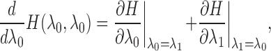 |
because the left-hand side is the limit of [H (λ1, λ1) − H (λ0, λ0)]/(λ1 − λ0) when λ1 → λ0. The partial derivative of H with respect to λ0 is equal to ΩAB′;α′tα′
PA
QB′, and in the limit this becomes [ΩAB′;α′]tα′
PA′
QB′. Similarly, the partial derivative of H with respect to λ1 is ΩAB′;αtαPAQB′, and in the limit λ1 → λ0 this becomes  . Finally,
 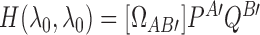 , and its derivative with respect to λ0 is
  . Gathering the results we find that
 |
and the final statement of Synge’s rule,
 |
4.6 |
follows from the fact that the tensors PM and QN, and the direction of the selected geodesic β, are all arbitrary. Equation (4.6) reduces to Eq. (4.3) when σ… is substituted in place of ΩAB′.
Parallel propagator
Tetrad on β
On the geodesic segment β that links x to x′ we introduce an orthonormal basis  that is parallel transported on the geodesic. The frame indices a, b,…, run from 0 to 3 and the basis vectors satisfy
 |
5.1 |
where ηab = diag(−1, 1, 1, 1) is the Minkowski metric (which we shall use to raise and lower frame indices). We have the completeness relations
 |
5.2 |
and we define a dual tetrad  by
by
 |
5.3 |
this is also parallel transported on β. In terms of the dual tetrad the completeness relations take the form
 |
5.4 |
and it is easy to show that the tetrad and its dual satisfy  and
and  . Equations (5.1) — (5.4) hold everywhere on β. In particular, with an appropriate change of notation they hold at x′ and x; for example,
  zz is the metric at x.
(You will have noticed that we use sans-serif symbols for the frame indices. This is to distinguish them from another set of frame indices that will appear below. The frame indices introduced here run from 0 to 3; those to be introduced later will run from 1 to 3.)
Definition and properties of the parallel propagator
Any vector field Aμ (z) on β can be decomposed in the basis  , and the vector’s frame components are given by
  . If Aμ is parallel transported on the geodesic, then the coefficients Aa are constants. The vector at x can then be expressed as
  , or
, or
 |
5.5 |
The object  is the parallel propagator: it takes a vector at x′ and parallel-transports it to x along the unique geodesic that links these points.
Similarly, we find that
 |
5.6 |
and we see that  performs the inverse operation: it takes a vector at x and parallel-transports it back to x′. Clearly,
 |
5.7 |
and these relations formally express the fact that  is the inverse of
  .
.
The relation  can also be expressed as
  , and this reveals that
 |
5.8 |
The ordering of the indices, and the ordering of the arguments, are arbitrary.
The action of the parallel propagator on tensors of arbitrary rank is easy to figure out. For example, suppose that the dual vector  is parallel transported on β. Then the frame components
  are constants, and the dual vector at x can be expressed as
  , or
, or
 |
5.9 |
It is therefore the inverse propagator  that takes a dual vector at x′ and parallel-transports it to x. As another example, it is easy to show that a tensor Aαβ at x obtained by parallel transport from x′ must be given by
 |
5.10 |
Here we need two occurrences of the parallel propagator, one for each tensorial index. Because the metric tensor is covariantly constant, it is automatically parallel transported on β, and a special case of Eq. (5.10) is  .
.
Because the basis vectors are parallel transported on β, they satisfy  at x and
  at x′. This immediately implies that the parallel propagators must satisfy
 |
5.11 |
Another useful property of the parallel propagator follows from the fact that if tμ = dzμ/dλ is tangent to the geodesic connecting x to x′, then  . Using Eqs. (3.3) and (3.4), this observation gives us the relations
 |
5.12 |
Coincidence limits
Eq. (5.5) and the completeness relations of Eqs. (5.2) or (5.4) imply that
 |
5.13 |
Other coincidence limits are obtained by differentiation of Eqs. (5.11). For example, the relation  implies
  , and at coincidence we have
 |
5.14 |
the second result was obtained by applying Synge’s rule on the first result. Further differentiation gives
 |
and at coincidence we have  , or
, or  . The coincidence limit for
  can then be obtained from Synge’s rule, and an additional application of the rule gives
  . Our results are
 |
5.15 |
Expansion of bitensors near coincidence
General method
We would like to express a bitensor Ωα′β′ (x, x′) near coincidence as an expansion in powers of −σα′ (x, x′), the closest analogue in curved spacetime to the flat-spacetime quantity (x − x′)α. For concreteness we shall consider the case of rank-2 bitensor, and for the moment we will assume that the tensorial indices all refer to the base point x′.
The expansion we seek is of the form
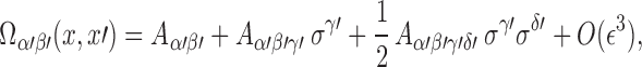 |
6.1 |
in which the “expansion coefficients” Aα′β′, Aα′β′γ′, and Aα′β′γ′δ′ are all ordinary tensors at x′; this last tensor is symmetric in the pair of indices γ′ and δ′, and ϵ measures the size of a typical component of σα′.
To find the expansion coefficients we differentiate Eq. (6.1) repeatedly and take coincidence limits. Equation (6.1) immediately implies  . After one differentiation we obtain
  , and at coincidence this reduces to
 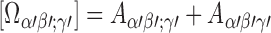 . Taking the coincidence limit after two differentiations yields
  . The expansion coefficients are therefore
 |
6.2 |
These results are to be substituted into Eq. (6.1), and this gives us Ωα′β′ (x,x′) to second order in ϵ.
Suppose now that the bitensor is Ωα′β, with one index referring to x′ and the other to x. The previous procedure can be applied directly if we introduce an auxiliary bitensor  whose indices all refer to the point x′. Then
  can be expanded as in Eq. (6.1), and the original bitensor is reconstructed as
  , or
, or
 |
6.3 |
The expansion coefficients can be obtained from the coincidence limits of  and its derivatives. It is convenient, however, to express them directly in terms of the original bitensor Ωα′β by substituting the relation
  and its derivatives. After using the results of Eq. (5.13) — (5.15) we find
 |
6.4 |
The only difference with respect to Eq. (6.3) is the presence of a Riemann-tensor term in Bα′β′γ′δ′.
Suppose finally that the bitensor to be expanded is Ωαβ, whose indices all refer to x. Much as we did before, we introduce an auxiliary bitensor  whose indices all refer to x′, we expand
  as in Eq. (6.1), and we then reconstruct the original bitensor. This gives us
 |
6.5 |
and the expansion coefficients are now
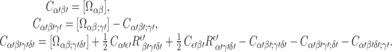 |
6.6 |
This differs from Eq. (6.4) by the presence of an additional Riemann-tensor term in Cα′β′γ′δ′.
Special cases
We now apply the general expansion method developed in the preceding subsection to the bitensors σα′β′, σα′β, and σαβ. In the first instance we have Aα′β′ = gα′β′, Aα′β′γ′ = 0, and  . In the second instance we have
  , and
, and  . In the third instance we have Cα′β′ = gα′β′, Cα′β′γ′ = 0, and
  . This gives us the expansions
 |
6.7 |
 |
6.8 |
 |
6.9 |
Taking the trace of the last equation returns 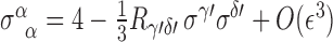 , or
, or
 |
6.10 |
where  was shown in Section 3.4 to describe the expansion of the congruence of geodesics that emanate from x′. Equation (6.10) reveals that timelike geodesics are focused if the Ricci tensor is nonzero and the strong energy condition holds: when
 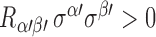 we see that θ* is smaller than 3, the value it would take in flat spacetime
The expansion method can easily be extended to bitensors of other tensorial ranks. In particular, it can be adapted to give expansions of the first derivatives of the parallel propagator. The expansions
 |
6.11 |
and thus easy to establish, and they will be needed in part III of this review.
Expansion of tensors
The expansion method can also be applied to ordinary tensor fields. For concreteness, suppose that we wish to express a rank-2 tensor Aαβ at a point x in terms of its values (and that of its covariant derivatives) at a neighbouring point x′. The tensor can be written as an expansion in powers of −σα′ (x, x′) and in this case we have
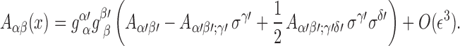 |
6.12 |
if the tensor field is parallel transported on the geodesic β that links x to x′, then Eq. (6.12) reduces to Eq. (5.10). The extension of this formula to tensors of other ranks is obvious.
To derive this result we express Aμν (z), the restriction of the tensor field on β, in terms of its tetrad components  . Recall from Section 5.1 that is an orthonormal basis that is parallel transported on β; recall also that the affine parameter γ ranges from γ0 (its value at x′) to γ1 (its value at x). We have
  , and Aab(γ1) can be expressed in terms of quantities at γ = γ0 by straightforward Taylor expansion. Since, for example,
 |
where we have used Eq. (3.4), we arrive at Eq. (6.12) after involving Eq. (5.6).
van Vleck determinant
Definition and properties
The van Vleck biscalar Δ(x, x′) is defined by
 |
7.1 |
As we shall show below, it can also be expressed as
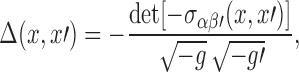 |
7.2 |
where g is the metric determinant at x and g′ the metric determinant at x′.
Eqs. 4.2) and (5.13) imply that at coincidence, 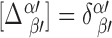 and [Δ] = 1. Equation (6.8), on the other hand, implies that near coincidence,
 |
7.3 |
so that
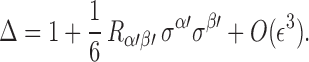 |
7.4 |
This last result follows from the fact that for a “small” matrix a, det(1 + a) = 1 + tr(a) + O (a2).
We shall prove below that the van Vleck determinant satisfies the differential equation
 |
7.5 |
which can also be written as (ln Δ),  , or
, or
 |
7.6 |
in the notation introduced in Section 3.4. Equation (7.6) reveals that the behaviour of the van Vleck determinant is governed by the expansion of the congruence of geodesics that emanate from x′. If θ* < 3, then the congruence expands less rapidly than it would in flat spacetime, and Δ increases along the geodesics. If, on the other hand, θ* > 3, then the congruence expands more rapidly than it would in flat spacetime, and Δ decreases along the geodesics. Thus, Δ > 1 indicates that the geodesics are undergoing focusing, while Δ < 1 indicates that the geodesics are undergoing defocusing. The connection between the van Vleck determinant and the strong energy condition is well illustrated by Eq. (7.4): the sign of Δ − 1 near x′ is determined by the sign of  .
.
Derivations
To show that Eq. (7.2) follows from Eq. (7.1) we rewrite the completeness relations at x,  , in the matrix form g−1 = EηET, where E denotes the 4 × 4 matrix whose entries correspond to
  . (In this translation we put tensor and frame indices on an equal footing.) With e denoting the determinant of this matrix, we have
  , or
, or  . Similarly, we rewrite the completeness relations at
  , in the matrix form g′−1 = E′ηE′T, where E′ is the matrix corresponding to
  . With e′ denoting its determinant, we have 1/g′ = − e′2, or
  . Now, the parallel propagator is defined by
  , and the matrix form of this equation is
  . The determinant of the parallel propagator is therefore
  . So we have
 |
7.7 |
and Eq. (7.2) follows from the fact that the matrix form of Eq. (7.1) is  , where σ is the matrix corresponding to σββ′.
To establish Eq. (7.5) we differentiate the relation  twice and obtain
 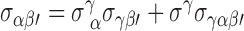 . If we replace the last factor by σσαβ′ and multiply both sides by − gα′α we find
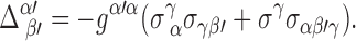 |
In this expression we make the substitution 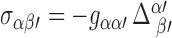 , which follows directly from Eq. (7.1). This gives us
 |
7.8 |
where we have used Eq. (5.11). At this stage we introduce an inverse  , to the van Vleck bitensor, defined by
 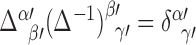 . After multiplying both sides of Eq. (7.8) by
  , we find
 |
and taking the trace of this equation yields
 |
We now recall the identity δ ln detM = Tr(M−1δM), which relates the variation of a determinant to the variation of the matrix elements. It implies, in particular, that  and we finally obtain
 |
7.9 |
Part II: Coordinate Systems
Riemann normal coordinates
Definition and coordinate transformation
Given a fixed base point x′ and a tetrad  (x′), we assign to a neighbouring point x the four coordinates
 |
8.1 |
where  is the dual tetrad attached to x′. The new coordinates
  are called Riemann normal coordinates (RNC), and they are such that
  , or
, or
 |
8.2 |
Thus,  is the squared geodesic distance between x and the base point x′. It is obvious that x′ is at the origin of the RNC, where
  .
.
If we move the point x to x + δx, the new coordinates change to  , so that
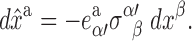 |
8.3 |
The coordinate transformation is therefore determined by  , and at coincidence we have
 |
8.4 |
the second result follows from the identities  and
and  .
.
It is interesting to note that the Jacobian of the transformation of Eq. (8.3),  , is given by
  , where g is the determinant of the metric in the original coordinates, and Δ(x,x′) is the Van Vleck determinant of Eq. (7.2). This result follows simply by writing the coordinate transformation in the form
  and computing the product of the determinants. It allows us to deduce that in RNC, the determinant of the metric is given by
 |
8.5 |
It is easy to show that the geodesics emanating from x′ are straight coordinate lines in RNC. The proper volume of a small comoving region is then equal to  , and this is smaller than the flat-spacetime value of
  if Δ > 1, that is, if the geodesics are focused by the spacetime curvature.
Metric near x′
We now would like to invert Eq. (8.3) in order to express the line element  in terms of the displacements
  . We shall do this approximately, by working in a small neighbourhood of x′. We recall the expansion of Eq. (6.8),
 |
and in this we substitute the frame decomposition of the Riemann tensor,  and the tetrad decomposition of the parallel propagator,
  , where
  (x) is the dual tetrad at x obtained by parallel transport of
  (x′). After some algebra we obtain
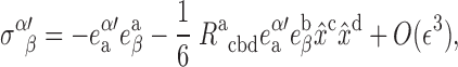 |
where we have used Eq. (8.1). Substituting this into Eq. (8.3) yields
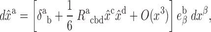 |
8.6 |
and this is easily inverted to give
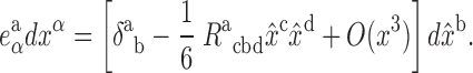 |
8.7 |
This is the desired approximate inversion of Eq. (8.3). It is useful to note that Eq. (8.7), when specialized from the arbitrary coordinates xα to  , gives us the components of the dual tetrad at x in RNC. And since
  in RNC, we immediately obtain the components of the parallel propagator:
 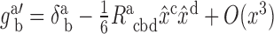 .
.
We are now in a position to calculate the metric in the new coordinates. We have  , and in this we substitute Eq. (8.7). The final result is
  , with
 |
8.8 |
The quantities Racbd appearing in Eq. (8.8) are the frame components of the Riemann tensor evaluated at the base point x′,
 |
8.9 |
and these are independent of  . They are also, by virtue of Eq. (8.4), the components of the (base-point) Riemann tensor in RNC, because Eq. (8.9) can also be expressed as
 |
which is the standard transformation law for tensor components.
It is obvious from Eq. (8.8) that  and
and  , where
 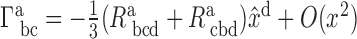 is the connection compatible with the metric gab. The Riemann normal coordinates therefore provide a constructive proof of the local flatness theorem.
Fermi normal coordinates
Fermi-Walker transport
Let γ be a timelike curve described by parametric relations zμ (τ) in which τ is proper time. Let uμ = dzμ/dτ be the curve’s normalized tangent vector, and let aμ = Duμ/dτ be its acceleration vector.
A vector field vμ is said to be Fermi-Walker transported on γ if it is a solution to the differential equation
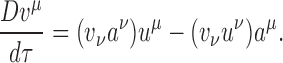 |
9.1 |
Notice that this reduces to parallel transport when aμ = 0 and γ is a geodesic.
The operation of Fermi-Walker (FW) transport satisfies two important properties. The first is that uμ is automatically FW transported along γ; this follows at once from Eq. (9.1) and the fact that uμ is orthogonal to aμ. The second is that if the vectors vμ and wμ are both FW transported along γ, then their inner product vμwμ is constant on γ: D (vμwμ)/dτ = 0; this also follows immediately from Eq. (9.1).
Tetrad and dual tetrad on γ
Let  be an arbitrary reference point on γ. At this point we erect an orthonormal tetrad
  where, as a modification to former usage, the frame index a runs from 1 to 3. We then propagate each frame vector on γ by FW transport; this guarantees that the tetrad remains orthonormal everywhere on γ. At a generic point z (τ) we have
 |
9.2 |
From the tetrad on γ we define a dual tetrad  by the relations
 |
9.3 |
this also is FW transported on γ. The tetrad and its dual give rise to the completeness relations
 |
9.4 |
Fermi normal coordinates
To construct the Fermi normal coordinates (FNC) of a point x in the normal convex neighbourhood of γ we locate the unique spacelike geodesic β that passes through x and intersects γ orthogonally. We denote the intersection point by  := z (t), with t denoting the value of the proper-time parameter at this point. To tensors at
  we assign indices
  and so on. The FNC of x are defined by
 |
9.5 |
the last statement determines  from the requirement that
  , the vector tangent to β at
  , be orthogonal to
  , the vector tangent to γ. From the definition of the FNC and the completeness relations of Eq. (9.4) it follows that
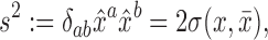 |
9.6 |
so that s is the spatial distance between  and x along the geodesic β. This statement gives an immediate meaning to
  , the spatial Fermi normal coordinates, and the time coordinate
  is simply proper time at the intersection point
  . The situation is illustrated in Figure 6.
Figure 6.

Fermi normal coordinates of a point x relative to a world line γ. The time coordinate t selects a particular point on the word line, and the disk represents the set of spacelike geodesics that intersect γ orthogonally at z (t). The unit vector  selects a particular geodesic among this set, and the spatial distance s selects a particular point on this geodesic.
Suppose that x is moved to x + δx. This typically induces a change in the spacelike geodesic β, which moves to β + δδβ, and a corresponding change in the intersection point  , which moves to
  , with
 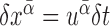 . The FNC of the new point are then
  and
and  , with x″ determined by
  . Expanding these relations to first order in the displacements, and simplifying using Eqs. (9.2), yields
 |
9.7 |
where μ is determined by  .
.
Coordinate displacements near γ
The relations of Eq. (9.7) can be expressed as expansions in powers of s, the spatial distance from  to x. For this we use the expansions of Eqs. (6.7) and (6.8), in which we substitute
  and
and  , where
  is a dual tetrad at x obtained by parallel transport of
  on the spacelike geodesic β. After some algebra we obtain
 |
where  are frame components of the acceleration vector, and
  are frame components of the Riemann tensor evaluated on γ. This last result is easily inverted to give
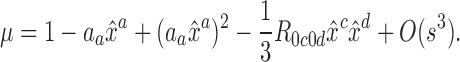 |
Proceeding similarly for the other relations of Eq. (9.7), we obtain
 |
9.8 |
and
 |
9.9 |
where 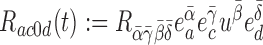 and
and 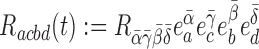 are additional frame components of the Riemann tensor evaluated on γ. (Note that frame indices are raised with δab.)
As a special case of Eqs. (9.8) and (9.9) we find that
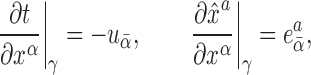 |
9.10 |
because in the limit  , the dual tetrad
  at x coincides with the dual tetrad
  at
at  . It follows that on γ, the transformation matrix between the original coordinates xα and the FNC (
 ) is formed by the Fermi-Walker transported tetrad:
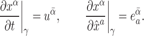 |
9.11 |
This implies that the frame components of the acceleration vector, aa (t), are also the components of the acceleration vector in FNC; orthogonality between  and
and  means that a0 = 0. Similarly, R0c 0d(t), R0cbd(t), and Racbd (t) are the components of the Riemann tensor (evaluated on γ) in Fermi normal coordinates.
Metric near γ
Inversion of Eqs. (9.8) and (9.9) gives
 |
9.12 |
and
 |
9.13 |
These relations, when specialized to the FNC, give the components of the dual tetrad at x. They can also be used to compute the metric at x, after invoking the completeness relations  . This gives
 |
9.14 |
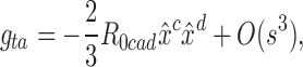 |
9.15 |
 |
9.16 |
This is the metric near γ in the Fermi normal coordinates. Recall that aa (t) are the components of the acceleration vector of γ — the timelike curve described by  — while R0c 0d(t), R0cbd(t), and Racbd (t) are the components of the Riemann tensor evaluated on γ.
Notice that on γ, the metric of Eqs. (9.14) — (9.16) reduces to gtt = −1 and gab = δab. On the other hand, the nonvanishing Christoffel symbols (on γ) are  ; these are zero (and the FNC enforce local flatness on the entire curve) when γ is a geodesic.
Thorne—Hartle—Zhang coordinates
The form of the metric can be simplified when the Ricci tensor vanishes on the world line:
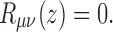 |
9.17 |
In such circumstances, a transformation from the Fermi normal coordinates  to the Thorne-Hartle-Zhang (THZ) coordinates
 brings the metric to the form
 |
9.18 |
 |
9.19 |
 |
9.20 |
We see that the transformation leaves gtt and gta unchanged, but that it diagonalizes gab. This metric was first displayed in Ref. [174] and the coordinate transformation was later produced by Zhang [187].
The key to the simplification comes from Eq. (9.17), which dramatically reduces the number of independent components of the Riemann tensor. In particular, Eq. (9.17) implies that the frame components Racbd of the Riemann tensor are completely determined by  , which in this special case is a symmetric-tracefree tensor. To prove this we invoke the completeness relations of Eq. (9.4) and take frame components of Eq. (9.17). This produces the three independent equations
 |
the last of which stating that  has a vanishing trace. Taking the trace of the first equation gives
  , and this implies that Racbd has five independent components. Since this is also the number of independent components of
  , we see that the first equation can be inverted — Racbd can be expressed in terms of
  . A complete listing of the relevant relations is
  , and
, and 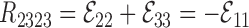 . These are summarized by
 |
9.21 |
and  satisfies
  .
.
We may also note that the relation δcdR0cad = 0, together with the usual symmetries of the Riemann tensor, imply that R0cad too possesses five independent components. These may thus be related to another symmetric-tracefree tensor  . We take the independent components to be
  , and
, and  , and it is easy to see that all other components can be expressed in terms of these. For example,
  and
and  . These relations are summarized by
 |
9.22 |
where εabc is the three-dimensional permutation symbol. The inverse relation is  .
.
Substitution of Eq. (9.21) into Eq. (9.16) gives
 |
and we have not yet achieved the simple form of Eq. (9.20). The missing step is the transformation from the FNC  to the THZ coordinates
  . This is given by
 |
9.23 |
It is easy to see that this transformation does not affect gtt nor gta at orders s and s2. The remaining components of the metric, however, transform according to gab (THZ) = gab (FNC) − ξa;b − ξb;a, where
 |
It follows that 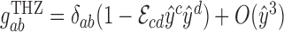 , which is just the same statement as in Eq. (9.20).
Alternative expressions for the components of the THZ metric are
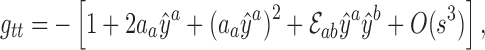 |
9.24 |
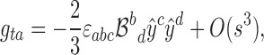 |
9.25 |
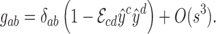 |
9.26 |
Retarded coordinates
Geometrical elements
We introduce the same geometrical elements as in Section 9: we have a timelike curve γ described by relations zμ (τ), its normalized tangent vector uμ = dzμ/dτ, and its acceleration vector aμ = Duμ/dτ. We also have an orthonormal triad  that is FW transported on the world line according to
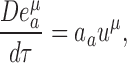 |
10.1 |
where 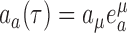 are the frame components of the acceleration vector. Finally, we have a dual tetrad
  , with
  and
and 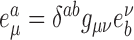 . The tetrad and its dual give rise to the completeness relations
 |
10.2 |
which are the same as in Eq. (9.4).
The Fermi normal coordinates of Section 9 were constructed on the basis of a spacelike geodesic connecting a field point x to the world line. The retarded coordinates are based instead on a null geodesic going from the world line to the field point. We thus let x be within the normal convex neighbourhood of γ, β be the unique future-directed null geodesic that goes from the world line to x, and x′ := z (u) be the point at which β intersects the world line, with u denoting the value of the proper-time parameter at this point.
From the tetrad at x′ we obtain another tetrad  at x by parallel transport on β. By raising the frame index and lowering the vectorial index we also obtain a dual tetrad at
  and
and  . The metric at x can be then be expressed as
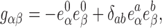 |
10.3 |
and the parallel propagator from x′ to x is given by
 |
10.4 |
Definition of the retarded coordinates
The quasi-Cartesian version of the retarded coordinates are defined by
 |
10.5 |
the last statement indicates that x′ and x are linked by a null geodesic. From the fact that σβ′ is a null vector we obtain
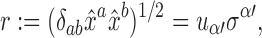 |
10.6 |
and r is a positive quantity by virtue of the fact that β is a future-directed null geodesic — this makes σβ′ past-directed. In flat spacetime, σβ′ = − (x − x′)β, and in a Lorentz frame that is momentarily comoving with the world line, r = t − t′ > 0; with the speed of light set equal to unity, r is also the spatial distance between x′ and x as measured in this frame. In curved spacetime, the quantity  can still be called the retarded distance between the point x and the world line. Another consequence of Eq. (10.5) is that
 |
10.7 |
where  is a unit spatial vector that satisfies δab Ωa Ωb = 1.
A straightforward calculation reveals that under a displacement of the point x, the retarded coordinates change according to
 |
10.8 |
where kα = σβ/r is a future-directed null vector at x that is tangent to the geodesic β. To obtain these results we must keep in mind that a displacement of x typically induces a simultaneous displacement of x′ because the new points x + δx and x′ + δx′ must also be linked by a null geodesic. We therefore have 0 = σ (x + δx, x′ + δx′) = σα δxα + σα′ δxα′, and the first relation of Eq. (10.8) follows from the fact that a displacement along the world line is described by δxα′ = uα′ δu.
The scalar field r (x) and the vector field kα(x)
If we keep x′ linked to x by the relation σ (x, x′) = 0, then the quantity
 |
10.9 |
can be viewed as an ordinary scalar field defined in a neighbourhood of γ. We can compute the gradient of r by finding how r changes under a displacement of x (which again induces a displacement of x′). The result is
 |
10.10 |
Similarly, we can view
 |
10.11 |
as an ordinary vector field, which is tangent to the congruence of null geodesics that emanate from x′. It is easy to check that this vector satisfies the identities
 |
10.12 |
from which we also obtain  . From this last result and Eq. (10.10) we deduce the important relation
 |
10.13 |
In addition, combining the general statement  cf. Eq. (5.12) — with Eq. (10.7) gives
 |
10.14 |
the vector at x is therefore obtained by parallel transport of  on α. From this and Eq. (10.4) we get the alternative expression
 |
10.15 |
which confirms that kα is a future-directed null vector field (recall that  is a unit vector).
The covariant derivative of kα can be computed by finding how the vector changes under a displacement of x. (It is in fact easier to calculate first how rkα changes, and then substitute our previous expression for ∂αr.) The result is
 |
10.16 |
From this we infer that kα satisfies the geodesic equation in affine-parameter form,  , and Eq. (10.13) informs us that the affine parameter is in fact r. A displacement along a member of the congruence is therefore given by dxα = kα
dr. Specializing to retarded coordinates, and using Eqs. (10.8) and (10.12), we find that this statement becomes du = 0 and
, and Eq. (10.13) informs us that the affine parameter is in fact r. A displacement along a member of the congruence is therefore given by dxα = kα
dr. Specializing to retarded coordinates, and using Eqs. (10.8) and (10.12), we find that this statement becomes du = 0 and 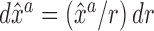 , which integrate to u = constant and
  , respectively, with Ωa still denoting a constant unit vector. We have found that the congruence of null geodesics emanating from x′ is described by
 |
10.17 |
in the retarded coordinates. Here, the two angles θA (A = 1, 2) serve to parameterize the unit vector Ωa, which is independent of r.
Eq. (10.16) also implies that the expansion of the congruence is given by
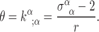 |
10.18 |
Using Eq. (6.10), we find that this becomes 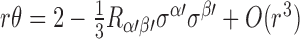 , or
, or
 |
10.19 |
after using Eq. (10.7). Here,  , and
, and  are the frame components of the Ricci tensor evaluated at x′. This result confirms that the congruence is singular at r = 0, because θ diverges as 2/r in this limit; the caustic coincides with the point x′.
Finally, we infer from Eq. (10.16) that kα is hypersurface orthogonal. This, together with the property that kα satisfies the geodesic equation in affine-parameter form, implies that there exists a scalar field u (x) such that
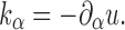 |
10.20 |
This scalar field was already identified in Eq. (10.8): it is numerically equal to the proper-time parameter of the world line at x′. We conclude that the geodesics to which kα is tangent are the generators of the null cone u = constant. As Eq. (10.17) indicates, a specific generator is selected by choosing a direction Ωa (which can be parameterized by two angles θA), and r is an affine parameter on each generator. The geometrical meaning of the retarded coordinates is now completely clear; it is illustrated in Figure 7.
Figure 7.

Retarded coordinates of a point x relative to a world line γ. The retarded time u selects a particular null cone, the unit vector 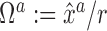 selects a particular generator of this null cone, and the retarded distance r selects a particular point on this generator. This figure is identical to Figure 4.
Frame components of tensor fields on the world line
The metric at x in the retarded coordinates will be expressed in terms of frame components of vectors and tensors evaluated on the world line γ. For example, if aα′ is the acceleration vector at x′, then as we have seen,
 |
10.21 |
are the frame components of the acceleration at proper time u.
Similarly,
 |
10.22 |
are the frame components of the Riemann tensor evaluated on γ. From these we form the useful combinations
 |
10.23 |
 |
10.24 |
 |
10.25 |
in which the quantities  depend on the angles θA only — they are independent of u and r.
We have previously introduced the frame components of the Ricci tensor in Eq. (10.19). The identity
 |
10.26 |
follows easily from Eqs. (10.23) — (10.25) and the definition of the Ricci tensor.
In Section 9 we saw that the frame components of a given tensor were also the components of this tensor (evaluated on the world line) in the Fermi normal coordinates. We should not expect this property to be true also in the case of the retarded coordinates: the frame components of a tensor are not to be identified with the components of this tensor in the retarded coordinates. The reason is that the retarded coordinates are in fact singular on the world line. As we shall see, they give rise to a metric that possesses a directional ambiguity at r = 0. (This can easily be seen in Minkowski spacetime by performing the coordinate transformation  .) Components of tensors are therefore not defined on the world line, although they are perfectly well defined for r ≠ 0. Frame components, on the other hand, are well defined both off and on the world line, and working with them will eliminate any difficulty associated with the singular nature of the retarded coordinates.
Coordinate displacements near γ
The changes in the quasi-Cartesian retarded coordinates under a displacement of x are given by Eq. (10.8). In these we substitute the standard expansions for σα′β′ and σα′β, as given by Eqs. (6.7) and (6.8), as well as Eqs. (10.7) and (10.14). After a straightforward (but fairly lengthy) calculation, we obtain the following expressions for the coordinate displacements:
 |
10.27 |
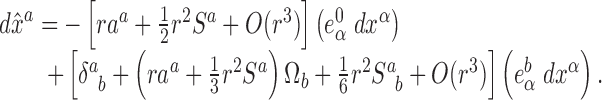 |
10.28 |
Notice that the result for du is exact, but that  is expressed as an expansion in powers of r
These results can also be expressed in the form of gradients of the retarded coordinates:
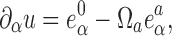 |
10.29 |
 |
10.30 |
Notice that Eq. (10.29) follows immediately from Eqs. (10.15) and (10.20). From Eq. (10.30) and the identity 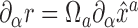 we also infer
 |
10.31 |
where we have used the facts that Sa = Sab Ωb and S = SaΩa; these last results were derived in Eqs. (10.24) and (10.25). It may be checked that Eq. (10.31) agrees with Eq. (10.10).
Metric near γ
It is straightforward (but fairly tedious) to invert the relations of Eqs. (10.27) and (10.28) and solve for  and
and  . The results are
 |
10.32 |
 |
10.33 |
These relations, when specialized to the retarded coordinates, give us the components of the dual tetrad  at x. The metric is then computed by using the completeness relations of Eq. (10.3). We find
 |
10.34 |
 |
10.35 |
 |
10.36 |
where a2 := δabaaab. We see (as was pointed out in Section 10.4) that the metric possesses a directional ambiguity on the world line: the metric at r = 0 still depends on the vector 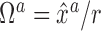 that specifies the direction to the point x. The retarded coordinates are therefore singular on the world line, and tensor components cannot be defined on γ.
By setting Sab = Sa = S = 0 in Eqs. (10.34)–(10.36) we obtain the metric of flat spacetime in the retarded coordinates. This we express as
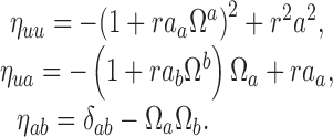 |
10.37 |
In spite of the directional ambiguity, the metric of flat spacetime has a unit determinant everywhere, and it is easily inverted:
 |
10.38 |
The inverse metric also is ambiguous on the world line.
To invert the curved-spacetime metric of Eqs. (10.34) — (10.36) we express it as gαβ = ηαβ + hαβ + O (r3) and treat hαβ = O (r2) as a perturbation. The inverse metric is then  , or
, or
 |
10.39 |
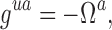 |
10.40 |
 |
10.41 |
The results for guu and gua are exact, and they follow from the general relations gαβ (∂αu)(∂βu) = 0 and gαβ (∂αu)(∂βr) = −1 that are derived from Eqs. (10.13) and (10.20).
The metric determinant is computed from 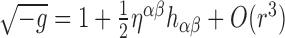 , which gives
 |
10.42 |
where we have substituted the identity of Eq. (10.26). Comparison with Eq. (10.19) gives us the interesting relation  , where θ is the expansion of the generators of the null cones u = constant.
Transformation to angular coordinates
Because the vector  satisfies δab Ωa Ωb = 1, it can be parameterized by two angles θA. A canonical choice for the parameterization is Ωa = (sin θ cos sin θ sin ϕ, cos θ). It is then convenient to perform a coordinate transformation from
  to (r, θA), using the relations
  . (Recall from Section 10.3 that the angles θA are constant on the generators of the null cones u = constant, and that r is an affine parameter on these generators. The relations
  therefore describe the behaviour of the generators.) The differential form of the coordinate transformation is
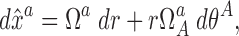 |
10.43 |
where the transformation matrix
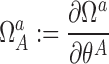 |
10.44 |
satisfies the identity  .
.
We introduce the quantities
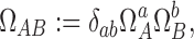 |
10.45 |
which act as a (nonphysical) metric in the subspace spanned by the angular coordinates. In the canonical parameterization, Ωab = diag(1, sin2 θ). We use the inverse of Ωab, denoted ΩAB, to raise upper-case Latin indices. We then define the new object
 |
10.46 |
which satisfies the identities
 |
10.47 |
The second result follows from the fact that both sides are simultaneously symmetric in a and b, orthogonal to Ωa and Ωb, and have the same trace.
From the preceding results we establish that the transformation from  to (r, θA) is accomplished by
 |
10.48 |
while the transformation from (r, θA) to  is accomplished by
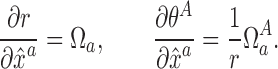 |
10.49 |
With these transformation rules it is easy to show that in the angular coordinates, the metric is given by
 |
10.50 |
 |
10.51 |
 |
10.52 |
 |
10.53 |
The results gru = −1, grr = 0, and grA = 0 are exact, and they follow from the fact that in the retarded coordinates, kα dxα = −du and kα∂α = ∂r.
The nonvanishing components of the inverse metric are
 |
10.54 |
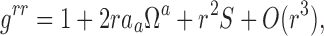 |
10.55 |
 |
10.56 |
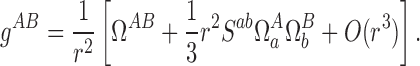 |
10.57 |
The results guu = 0, gur = −1, and guA = 0 are exact, and they follow from the same reasoning as before.
Finally, we note that in the angular coordinates, the metric determinant is given by
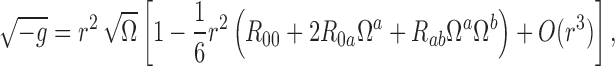 |
10.58 |
where Ω is the determinant of Ωab; in the canonical parameterization,  .
.
Specialization to aμ = 0 = Rμν
In this subsection we specialize our previous results to a situation where γ is a geodesic on which the Ricci tensor vanishes. We therefore set aμ = 0 = Rμν everywhere on γ.
We have seen in Section 9.6 that when the Ricci tensor vanishes on γ, all frame components of the Riemann tensor can be expressed in terms of the symmetric-tracefree tensors  and
and  . The relations are
  , and
, and  . These can be substituted into Eqs. (10.23) — (10.25) to give
 |
10.59 |
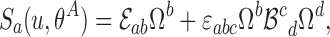 |
10.60 |
 |
10.61 |
In these expressions the dependence on retarded time u is contained in  and
and  , while the angular dependence is encoded in the unit vector Ωa.
It is convenient to introduce the irreducible quantities
 |
10.62 |
 |
10.63 |
 |
10.64 |
 |
10.65 |
 |
10.66 |
These are all orthogonal to  and
and  . In terms of these Eqs. (10.59) — (10.61) become
 |
10.67 |
 |
10.68 |
 |
10.69 |
When Eqs. (10.67) — (10.69) are substituted into the metric tensor of Eqs. (10.34) — (10.36) — in which aa is set equal to zero — we obtain the compact expressions
 |
10.70 |
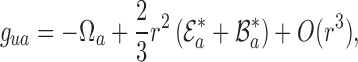 |
10.71 |
 |
10.72 |
The metric becomes
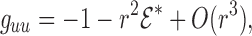 |
10.73 |
 |
10.74 |
 |
10.75 |
 |
10.76 |
after transforming to angular coordinates using the rules of Eq. (10.48). Here we have introduced the projections
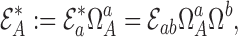 |
10.77 |
 |
10.78 |
 |
10.79 |
 |
10.80 |
It may be noted that the inverse relations are  , and
, and 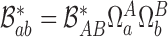 , where
  was introduced in Eq. (10.46).
Transformation between Fermi and retarded coordinates; advanced point
A point x in the normal convex neighbourhood of a world line γ can be assigned a set of Fermi normal coordinates (as in Section 9), or it can be assigned a set of retarded coordinates (Section 10). These coordinate systems can obviously be related to one another, and our first task in this section (which will occupy us in Sections 11.1–11.3) will be to derive the transformation rules. We begin by refining our notation so as to eliminate any danger of ambiguity.
The Fermi normal coordinates of x refer to a point  on γ that is related to x by a spacelike geodesic that intersects γ orthogonally; see Figure 8. We refer to this point as x’s simultaneous point, and to tensors at
  we assign indices
  etc. We let (t, sωa) be the Fermi normal coordinates of x, with t denoting the value of γ’s proper-time parameter at
  representing the proper distance from
  to x along the spacelike geodesic, and ωa denoting a unit vector (δabωaωb = 1) that determines the direction of the geodesic. The Fermi normal coordinates are defined by
  and
and  . Finally, we denote by
  the tetrad at x that is obtained by parallel transport of
  on the spacelike geodesic.
Figure 8.

The retarded, simultaneous, and advanced points on a world line γ. The retarded point x′ := z (u) is linked to x by a future-directed null geodesic. The simultaneous point  is linked to x by a spacelike geodesic that intersects γ orthogonally. The advanced point x″:= z (μ) is linked to x by a past-directed null geodesic.
The retarded coordinates of x refer to a point x′ := z (u) on γ that is linked to x by a future-directed null geodesic; see Figure 8. We refer to this point as x’s retarded point, and to tensors at x′ we assign indices α′, β′, etc. We let (u, r Ωa) be the retarded coordinates of x, with u denoting the value of γ’s proper-time parameter at x″ representing the affine-parameter distance from x′ to x along the null geodesic, and Ωa denoting a unit vector (δab Ωa Ωb = 1) that determines the direction of the geodesic. The retarded coordinates are defined by  and σ (x, x′) = 0. Finally, we denote by
  the tetrad at x that is obtained by parallel transport of
  on the null geodesic.
The reader who does not wish to follow the details of this discussion can be informed that: (i) our results concerning the transformation from the retarded coordinates (u, r, Ωa) to the Fermi normal coordinates (t, s, ωa) are contained in Eqs. (11.1) — (11.3) below; (ii) our results concerning the transformation from the Fermi normal coordinates (t, s, ωa) to the retarded coordinates (u, r, Ωa) are contained in Eqs. (11.4) — (11.6); (iii) the decomposition of each member of  in the tetrad
  is given in retarded coordinates by Eqs. (11.7) and (11.8); and (iv) the decomposition of each member of
  in the tetrad
  is given in Fermi normal coordinates by Eqs. (11.9) and (11.10).
Our final task will be to define, along with the retarded and simultaneous points, an advanced point x″ on the world line γ; see Figure 8. This is taken on in Section 11.4.
From retarded to Fermi coordinates
Quantities at  can be related to quantities at x′ := z (u) by Taylor expansion along the world line γ. To implement this strategy we must first find an expression for Δ := t − u. (Although we use the same notation, this should not be confused with the van Vleck determinant introduced in Section 7.)
Consider the function p (τ) of the proper-time parameter τ defined by
 |
in which x is kept fixed and in which z (τ) is an arbitrary point on the world line. We have that p (u) = r and p (t) = 0, and Δ can ultimately be obtained by expressing p (t) as p (u + Δ) and expanding in powers of Δ. Formally,
 |
where overdots (or a number within brackets) indicate repeated differentiation with respect to τ. We have
 |
where aμ = Duμ/dτ, ȧμ = Daμ/dτ, and äμ = Dȧμ/dτ.
We now express all of this in retarded coordinates by invoking the expansion of Eq. (6.7) for σσα′β (as well as additional expansions for the higher derivatives of the world function, obtained by further differentiation of this result) and the relation  first derived in Eq. (10.7). With a degree of accuracy sufficient for our purposes we obtain
 |
where S = Ra0b0Ωa Ωb was first introduced in Eq. (10.25), and where  are the frame components of the covariant derivative of the acceleration vector. To arrive at these results we made use of the identity
  that follows from the fact that aμ is orthogonal to uμ. Notice that there is no distinction between the two possible interpretations ȧa := daa/dτ and
  for the quantity ȧa (τ); their equality follows at once from the substitution of
  (which states that the basis vectors are Fermi-Walker transported on the world line) into the identity
 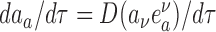 .
.
Collecting our results we obtain
 |
which can readily be solved for Δ := t − u expressed as an expansion in powers of r. The final result is
 |
11.1 |
where we show explicitly that all frame components are evaluated at the retarded point z (u).
To obtain relations between the spatial coordinates we consider the functions
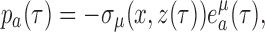 |
in which x is fixed and z (τ) is an arbitrary point on γ. We have that the retarded coordinates are given by r Ωa = pa (u), while the Fermi coordinates are given instead by sωa = pa (t) = pa (u + Δ). This last expression can be expanded in powers of Δ, producing
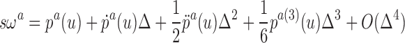 |
with
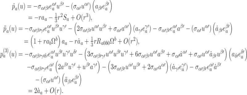 |
To arrive at these results we have used the same expansions as before and re-introduced Sa = Ra0b0Ωb − Rab0cΩb Ωc, as it was first defined in Eq. (10.24).
Collecting our results we obtain
 |
which becomes
 |
11.2 |
after substituting Eq. (11.1) for Δ := t − u. From squaring Eq. (11.2) and using the identity δabωa ωb = 1 we can also deduce
 |
11.3 |
for the spatial distance between x and z (t).
From Fermi to retarded coordinates
The techniques developed in the preceding subsection can easily be adapted to the task of relating the retarded coordinates of x to its Fermi normal coordinates. Here we use  as the reference point and express all quantities at x′ := z (u) as Taylor expansions about τ = t.
We begin by considering the function
 |
of the proper-time parameter τ on γ. We have that 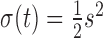 and σ (u) = 0, and Δ := t − u is now obtained by expressing σ (u) as σ (t − Δ) and expanding in powers of Δ. Using the fact that
  , we have
 |
Expressions for the derivatives of p (τ) evaluated at τ = t can be constructed from results derived previously in Section 11.1: it suffices to replace all primed indices by barred indices and then substitute the relation 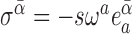 that follows immediately from Eq. (9.5). This gives
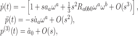 |
and then
 |
after recalling that p (t) = 0. Solving for Δ as an expansion in powers of s returns
 |
11.4 |
in which we emphasize that all frame components are evaluated at the simultaneous point z (t).
An expression for r = p (u) can be obtained by expanding p (t − Δ) in powers of Δ. We have
 |
and substitution of our previous results gives
 |
11.5 |
for the retarded distance between x and z (u).
Finally, the retarded coordinates r Ωa = pa (u) can be related to the Fermi coordinates by expanding pa (t − Δ) in powers of Δ, so that
 |
Results from the preceding subsection can again be imported with mild alterations, and we find
 |
This, together with Eq. (11.4), gives
 |
11.6 |
It may be checked that squaring this equation and using the identity δab Ωa Ωb = 1 returns the same result as Eq. (11.5).
Transformation of the tetrads at x
Recall that we have constructed two sets of basis vectors at x. The first set is the tetrad  that is obtained by parallel transport of
  on the spacelike geodesic that links x to the simultaneous point
  . The second set is the tetrad
  that is obtained by parallel transport of
  on the null geodesic that links x to the retarded point x′ := z (u). Since each tetrad forms a complete set of basis vectors, each member of
  can be decomposed in the tetrad
  , and correspondingly, each member of
  can be decomposed in the tetrad
  . These decompositions are worked out in this subsection. For this purpose we shall consider the functions
 |
in which x is a fixed point in a neighbourhood of γ, z (τ) is an arbitrary point on the world line, and  is the parallel propagator on the unique geodesic that links x to z. We have
  , and
, and  .
.
We begin with the decomposition of  in the tetrad
  associated with the retarded point z (u). This decomposition will be expressed in the retarded coordinates as an expansion in powers of r. As in Section 9.1 we express quantities at z (t) in terms of quantities at z (u) by expanding in powers of Δ := t − u. We have
 |
with
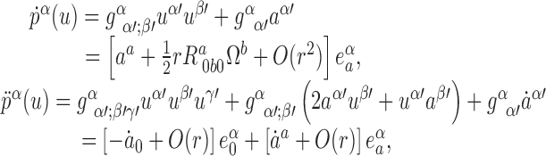 |
where we have used the expansions of Eq. (6.11) as well as the decompositions of Eq. (10.4). Collecting these results and substituting Eq. (11.1) for Δ yields
 |
11.7 |
Similarly, we have
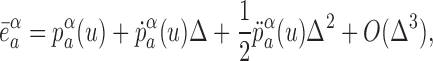 |
with
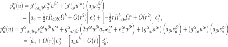 |
and all this gives
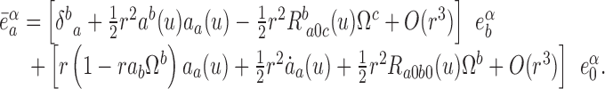 |
11.8 |
We now turn to the decomposition of  in the tetrad
  associated with the simultaneous point z (t). This decomposition will be expressed in the Fermi normal coordinates as an expansion in powers of. Here, as in Section 9.2, we shall express quantities at z (u) in terms of quantities at z (t). We begin with
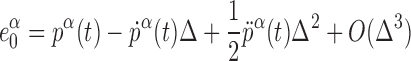 |
and we evaluate the derivatives of pα (τ) at τ = t. To accomplish this we rely on our previous results (replacing primed indices with barred indices), on the expansions of Eq. (6.11), and on the decomposition of  in the tetrads at x and
  . This gives
 |
and we finally obtain
 |
11.9 |
Similarly, we write
 |
in which we substitute
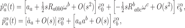 |
as well as Eq. (11.4) for Δ := t − u. Our final result is
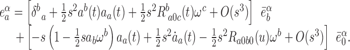 |
11.10 |
Advanced point
It will prove convenient to introduce on the world line, along with the retarded and simultaneous points, an advanced point associated with the field point x. The advanced point will be denoted x ″ := z (v), with v denoting the value of the proper-time parameter at x ″; to tensors at this point we assign indices α ″, β ″, etc. The advanced point is linked to by a past-directed null geodesic (refer back to Figure 8), and it can be located by solving σ (x, x″) = 0 together with the requirement that σα″ (x,x ″) be a future-directed null vector. The affine-parameter distance between x and x″ along the null geodesic is given by
 |
11.11 |
and we shall call this the advanced distance between x and the world line. Notice that radv is a positive quantity.
We wish first to find an expression for v in terms of the retarded coordinates of x. For this purpose we define Δ″ := v − u and re-introduce the function σ (τ) := σ (x, z (τ)) first considered in Section 11.2. We have that σ (v) = σ (u) = 0, and Δ′ can ultimately be obtained by expressing σ (v) as σ (u + Δ′) and expanding in powers of Δ′. Recalling that 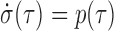 , we have
 |
Using the expressions for the derivatives of p (τ) that were first obtained in Section 11.1, we write this as
 |
Solving for Δ′ as an expansion in powers of r, we obtain
 |
11.12 |
in which all frame components are evaluated at the retarded point z (u).
Our next task is to derive an expression for the advanced distance radv. For this purpose we observe that radv = −p (v) = − p (u + Δ′), which we can expand in powers of Δ′ := v − u. This gives
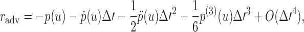 |
which then becomes
 |
After substituting Eq. (11.12) for Δ′ and witnessing a number of cancellations, we arrive at the simple expression
 |
11.13 |
From Eqs. (10.29), (10.30), and (11.12) we deduce that the gradient of the advanced time is given by
 |
11.14 |
where the expansion in powers of r was truncated to a sufficient number of terms. Similarly, Eqs. (10.30), (10.31), and (11.13) imply that the gradient of the advanced distance is given by
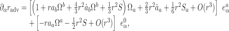 |
11.15 |
where Sa and S were first introduced in Eqs. (10.24) and (10.25), respectively. We emphasize that in Eqs. (11.14) and (11.15), all frame components are evaluated at the retarded point z (u).
Part III: Green’s Functions
Scalar Green’s functions in flat spacetime
Green’s equation for a massive scalar field
To prepare the way for our discussion of Green’s functions in curved spacetime, we consider first the slightly nontrivial case of a massive scalar field Φ(x) in flat spacetime. This field satisfies the wave equation
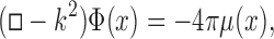 |
12.1 |
where □ = ηαβ∂α∂β is the wave operator, μ (x) a prescribed source, and where the parameter k has a dimension of inverse length. We seek a Green’s function G (x, x′) such that a solution to Eq. (12.1) can be expressed as
 |
12.2 |
where the integration is over all of Minkowski spacetime. The relevant wave equation for the Green’s function is
 |
12.3 |
where δ4(x − x′) = δ (t − t′)δ (x − x′)δ (y − y′)δ (z − z′) is a four-dimensional Dirac distribution in flat spacetime. Two types of Green’s functions will be of particular interest: the retarded Green’s function, a solution to Eq. (12.3) with the property that it vanishes when is in the past of x′, and the advanced Green’s function, which vanishes when x is in the future of x′.
To solve Eq. (12.3) we appeal to Lorentz invariance and the fact that the spacetime is homogeneous to argue that the retarded and advanced Green’s functions must be given by expressions of the form
 |
12.4 |
where 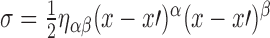 is Synge’s world function in flat spacetime, and where g (σ) is a function to be determined. For the remainder of this section we set x′ = 0 without loss of generality.
Integration over the source
The Dirac functional on the right-hand side of Eq. (12.3) is a highly singular quantity, and we can avoid dealing with it by integrating the equation over a small four-volume V that contains x′ = 0. This volume is bounded by a closed hypersurface ∂V. After using Gauss’ theorem on the first term of Eq. (12.3), we obtain ∮∂VGαd∑α −k2 ∫V G dV = −4π, where dσα is a surface element on ∂V. Assuming that the integral of G over V goes to zero in the limit V → 0, we have
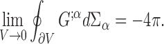 |
12.5 |
It should be emphasized that the four-volume V must contain the point x′.
To examine Eq. (12.5) we introduce coordinates (w, χ, θ, θ) defined by
 |
and we let ∂V be a surface of constant w. The metric of flat spacetime is given by
 |
in the new coordinates, where d Ω2 = dθ2 + sin2
θ dϕ2. Notice that w is a timelike coordinate when cos2χ > 0, and that χ is then a spacelike coordinate; the roles are reversed when cos2χ < 0. Straightforward computations reveal that in these coordinates,  , and the only nonvanishing component of the surface element is dΣw = w3 sin2
χdχd Ω, where d Ω = sin θ dθdϕ. To calculate the gradient of the Green’s function we express it as
, and the only nonvanishing component of the surface element is dΣw = w3 sin2
χdχd Ω, where d Ω = sin θ dθdϕ. To calculate the gradient of the Green’s function we express it as  , with the upper (lower) sign belonging to the retarded (advanced) Green’s function. Calculation gives G;α
dΣα = θ (± cos χ)w4 sin2
χg′(σ) dχd Ω, with a prime indicating differentiation with respect to σ; it should be noted that derivatives of the step function do not appear in this expression.
, with the upper (lower) sign belonging to the retarded (advanced) Green’s function. Calculation gives G;α
dΣα = θ (± cos χ)w4 sin2
χg′(σ) dχd Ω, with a prime indicating differentiation with respect to σ; it should be noted that derivatives of the step function do not appear in this expression.
Integration of G;αdΣα with respect to d Ω is immediate, and we find that Eq. (12.5) reduces to
 |
12.6 |
for the retarded Green’s function, the step function restricts the domain of integration to 0 < χ < π/2, in which σ increases from  to
to  . Changing the variable of integration from χ to σ transforms Eq. (12.6) into
 |
12.7 |
where  . For the advanced Green’s function, the domain of integration is π/2 < χ < π, in which σ decreases from
  to
to  . Changing the variable of integration from χ to σ also produces Eq. (12.7).
Singular part of g (σ)
We have seen that Eq. (12.7) properly encodes the influence of the singular source term on both the retarded and advanced Green’s function. The function g (σ) that enters into the expressions of Eq. (12.4) must therefore be such that Eq. (12.7) is satisfied. It follows immediately that g (σ) must be a singular function, because for a smooth function the integral of Eq. (12.7) would be of order ϵ and the left-hand side of Eq. (12.7) could never be made equal to −1. The singularity, however, must be integrable, and this leads us to assume that g′(σ) must be made out of Dirac δ-functions and derivatives.
We make the ansatz
 |
12.8 |
where V (σ) is a smooth function, and A, B, C, … are constants. The first term represents a function supported within the past and future light cones of x′ = 0; we exclude a term proportional to θ (σ) for reasons of causality. The other terms are supported on the past and future light cones. It is sufficient to take the coefficients in front of the δ-functions to be constants. To see this we invoke the distributional identities
 |
12.9 |
from which it follows that σ2δ′(σ) = σ3δ ″(σ) = … =0. A term like f (σ)δ (σ) is then distributionally equal to f (0)δ (σ), while a term like f (σ)δ′(σ) is distributionally equal to f (σ)δ′(σ) − f′(0)δ (σ), and a term like f (σ)δ ″(σ) is distributionally equal to f (0)δ ″(σ) − 2f′(0)δ′ (σ) + 2f ″(0)δ (σ); here f (σ) is an arbitrary test function. Summing over such terms, we recover an expression of the form of Eq. (12.9), and there is no need to make A, B, C, … functions of σ.
Differentiation of Eq. (12.8) and substitution into Eq. (12.7) yields
 |
where overdots (or a number within brackets) indicate repeated differentiation with respect to ξ:= σ/ϵ. The limit ϵ → 0 exists if and only if B = C = … = 0. In the limit we must then have Aẇ (0) = 1, which implies A =1. We conclude that g (σ) must have the form of
 |
12.10 |
with V (σ) a smooth function that cannot be determined from Eq. (12.7) alone.
Smooth part of g (σ)
To determine V (σ) we must go back to the differential equation of Eq. (12.3). Because the singular structure of the Green’s function is now under control, we can safely set x ≠ x′ = 0 in the forthcoming operations. This means that the equation to solve is in fact (□ − 2)g (σ) = 0, the homogeneous version of Eq. (12.3). We have ∇αg = g′σα, ∇α ∇βg = g ″σασβ + g′σαβ, □g = 2σg ″ + 4g′, so that Green’s equation reduces to the ordinary differential equation
 |
12.11 |
if we substitute Eq. (12.10) into this we get
 |
where we have used the identities of Eq. (12.9). The left-hand side will vanish as a distribution if we set
 |
12.12 |
These equations determine V (σ) uniquely, even in the absence of a second boundary condition at σ = 0, because the differential equation is singular at σ = 0 while V is known to be smooth.
To solve Eq. (12.12) we let V = F (z)/z, with  . This gives rise to Bessel’s equation for the new function F:
 |
The solution that is well behaved near z = 0 is F = aJ1(z), where a is a constant to be determined. We have that  for small values of z, and it follows that V ∼ a/2. From Eq. (12.12) we see that a = − k2. So we have found that the only acceptable solution to Eq. (12.12) is
 |
12.13 |
To summarize, the retarded and advanced solutions to Eq. (12.3) are given by Eq. (12.4) with g (σ) given by Eq. (12.10) and V (σ) given by Eq. (12.13).
Advanced distributional methods
The techniques developed previously to find Green’s functions for the scalar wave equation are limited to flat spacetime, and they would not be very useful for curved spacetimes. To pursue this generalization we must introduce more powerful distributional methods. We do so in this subsection, and in the next we shall use them to recover our previous results.
Let θ+ (x, Σ) be a generalized step function, defined to be one when x is in the future of the spacelike hypersurface Σ and zero otherwise. Similarly, define θ−(x, Σ) := 1 − θ+ (x, Σ) to be one when x is in the past of the spacelike hypersurface Σ and zero otherwise. Then define the light-cone step functions
 |
12.14 |
so that θ+ (−σ) is one if x is within I+ (x′), the chronological future of x′, and zero otherwise, and θ−(−σ) is one if x is within I−(x′), the chronological past of x′, and zero otherwise; the choice of hypersurface is immaterial so long as Σ is spacelike and contains the reference point x′. Notice that θ+ (−σ) + θ−(−σ) = θ (−σ). Define also the light-cone Dirac functionals
 |
12.15 |
so that δ+ (σ), when viewed as a function of x, is supported on the future light cone of x′, while δ−(σ) is supported on its past light cone. Notice that δ+ (σ) + δ−(σ) = δ (σ). In Eqs. (12.14) and (12.15), σ is the world function for flat spacetime; it is negative when x and x′ are timelike related, and positive when they are spacelike related.
The distributions θ±(−σ) and δ±(σ) are not defined at x = x′ and they cannot be differentiated there. This pathology can be avoided if we shift σ by a small positive quantity ϵ. We can therefore use the distributions θ±(−σ − ϵ) and θ±(σ + ϵ) in some sensitive computations, and then take the limit ϵ → 0+. Notice that the equation σ + ϵ = 0 describes a two-branch hyperboloid that is located just within the light cone of the reference point x′. The hyperboloid does not include x′, and θ+ (x, Σ) is one everywhere on its future branch, while θ −(x, Σ) is one everywhere on its past branch. These factors, therefore, become invisible to differential operators. For example, θ′+ (−σ − ϵ) = θ+ (x, Σ)θ′(−σ − ϵ) = −θ+(x, Σ)δ (σ + ϵ) = − δ+ (σ + ϵ). This manipulation shows that after the shift from σ to σ + ϵ, the distributions of Eqs. (12.14) and (12.15) can be straightforwardly differentiated with respect to σ.
In the next paragraphs we shall establish the distributional identities
 |
12.16 |
 |
12.17 |
 |
12.18 |
in four-dimensional flat spacetime. These will be used in the next subsection to recover the Green’s functions for the scalar wave equation, and they will be generalized to curved spacetime in Section 13.
The derivation of Eqs. (12.16) — (12.18) relies on a “master” distributional identity, formulated in three-dimensional flat space:
 |
12.19 |
with  . This follows from yet another identity, ∇2r−1 = − 4πδ3(x), in which we write the left-hand side as limϵ→0+ ∇2R−1; since R−1 is nonsingular at x = 0 it can be straightforwardly differentiated, and the result is ∇2R −1 = −6ϵ/R5, from which Eq. (12.19) follows.
To prove Eq. (12.16) we must show that ϵδ±(σ + ϵ) vanishes as a distribution in the limit ϵ − 0+. For this we must prove that a functional of the form
 |
where f (x) = f (t, x) is a smooth test function, vanishes for all such functions f. Our first task will be to find a more convenient expression for θ±(σ + ϵ). Once more we set x′ = 0 (without loss of generality) and we note that 2(σ + ϵ) = −t2 + r2 + 2ϵ = −(t − R)(t + R), where we have used Eq. (12.19). It follows that
 |
12.20 |
and from this we find
 |
which establishes Eq. (12.16).
The validity of Eq. (12.17) is established by a similar computation. Here we must show that a functional of the form
 |
vanishes for all test functions f. We have
 |
and the identity of Eq. (12.17) is proved. In these manipulations we have let an overdot indicate partial differentiation with respect to t, and we have used ∂R/de = 1/R.
To establish Eq. (12.18) we consider the functional
 |
and show that it evaluates to 2πf (0, 0). We have
 |
as required. This proves that Eq. (12.18) holds as a distributional identity in four-dimensional flat spacetime.
Alternative computation of the Green’s functions
The retarded and advanced Green’s functions for the scalar wave equation are now defined as the limit of the functions  when ϵ → 0+. For these we make the ansatz
 |
12.21 |
and we shall prove that  satisfies Eq. (12.3) in the limit. We recall that the distributions θ± and δ± were defined in the preceding subsection, and we assume that V (σ) is a smooth function of
  ; because this function is smooth, it is not necessary to evaluate V at σ + ϵ in Eq. (12.21). We recall also that θ+ and δ+ are nonzero when x is in the future of x′, while θ− and δ− are nonzero when x is in the past of x′. We will therefore prove that the retarded and advanced Green’s functions are of the form
 |
12.22 |
and
 |
12.23 |
where Σ is a spacelike hypersurface that contains x′. We will also determine the form of the function V (σ).
The functions that appear in Eq. (12.21) can be straightforwardly differentiated. The manipulations are similar to what was done in Section 12.4, and dropping all labels, we obtain (□ − k2)G = 2σ G″ + 4G′ − k2G, with a prime indicating differentiation with respect to σ. From Eq. (12.21) we obtain G′ = δ′ − Vδ + V′θ and G″ = δ″ − Vδ′ − 2V′δ + V″θ. The identities of Eq. (12.9) can be expressed as (σ + ϵ)δ′(σ + ϵ) = − δ (σ + ϵ) and (σ + ϵ)δ″ (σ + ϵ) = −2δ′(σ + ϵ), and combining this with our previous results gives
 |
According to Eq. (12.16) — (12.18), the last two terms on the right-hand side disappear in the limit ϵ → 0+, and the third term becomes − 4πδ4(x − x′). Provided that the first two terms vanish also, we recover (□ − k2)G (x, x′) = − 4πδ4(x − x′) in the limit, as required. Thus, the limit of  when ϵ − 0+ will indeed satisfy Green’s equation provided that V (σ) is a solution to
 |
12.24 |
these are the same statements as in Eq. (12.12). The solution to these equations was produced in Eq. (12.13):
 |
12.25 |
and this completely determines the Green’s functions of Eqs. (12.22) and (12.23).
Distributions in curved spacetime
The distributions introduced in Section 12.5 can also be defined in a four-dimensional spacetime with metric gαβ. Here we produce the relevant generalizations of the results derived in that section.
Invariant Dirac distribution
We first introduce δ4(x,x′), an invariant Dirac functional in a four-dimensional curved spacetime. This is defined by the relations
 |
13.1 |
where f (x) is a smooth test function, V any four-dimensional region that contains x′, and V′ any four-dimensional region that contains x. These relations imply that δ4(x,x′) is symmetric in its arguments, and it is easy to see that
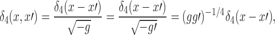 |
13.2 |
where δ4(x − x′) = δ (x0 − x′0)δ (x1 − x′1)δ (x2 − x′2)δ (x3 − x′3) is the ordinary (coordinate) four-dimensional Dirac functional. The relations of Eq. (13.2) are all equivalent because f (x)δ4(x, x′) = f (x′)δ4(x,x′) is a distributional identity; the last form is manifestly symmetric in x and x′.
The invariant Dirac distribution satisfies the identities
 |
13.3 |
where Ω…(x, x′) is any bitensor and  are parallel propagators. The first identity follows immediately from the definition of the δ-function. The second and third identities are established by showing that integration against a test function f (x) gives the same result from both sides. For example, the first of the Eqs. (13.1) implies
 |
and on the other hand,
 |
which establishes the second identity of Eq. (13.3). Notice that in these manipulations, the integrations involve scalar functions of the coordinates x; the fact that these functions are also vectors with respect to x′ does not invalidate the procedure. The third identity of Eq. (13.3) is proved in a similar way.
Light-cone distributions
For the remainder of Section 13 we assume that  , so that a unique geodesic β links these two points. We then let σ (x,x′) be the curved spacetime world function, and we define light-cone step functions by
 |
13.4 |
where θ+ (x, Σ) is one when x is in the future of the spacelike hypersurface Σ and zero otherwise, and θ −(x, Σ) = 1 − θ+ (x, Σ). These are immediate generalizations to curved spacetime of the objects defined in flat spacetime by Eq. (12.14). We have that θ+ (−σ) is one when x is within I+(x′), the chronological future of x′, and zero otherwise, and θ −(−σ) is one when x is within I−(x′), the chronological past of x′, and zero otherwise. We also have θ+ (−σ) + θ−(−σ) = θ (−σ).
We define the curved-spacetime version of the light-cone Dirac functionals by
 |
13.5 |
an immediate generalization of Eq. (12.15). We have that δ+ (σ), when viewed as a function of x, is supported on the future light cone of x′, while δ − (σ) is supported on its past light cone. We also have δ+(σ) + δ −(σ) = δ (σ), and we recall that σ is negative when x and x′ are timelike related, and positive when they are spacelike related.
For the same reasons as those mentioned in Section 12.5, it is sometimes convenient to shift the argument of the step and δ-functions from σ to σ + ϵ, where ϵ is a small positive quantity. With this shift, the light-cone distributions can be straightforwardly differentiated with respect to σ. For example,  , with a prime indicating differentiation with respect to σ.
We now prove that the identities of Eq. (12.16)–(12.18) generalize to
 |
13.6 |
 |
13.7 |
 |
13.8 |
in a four-dimensional curved spacetime; the only differences lie with the definition of the world function and the fact that it is the invariant Dirac functional that appears in Eq. (13.8). To establish these identities in curved spacetime we use the fact that they hold in flat spacetime — as was shown in Section 12.5 — and that they are scalar relations that must be valid in any coordinate system if they are found to hold in one. Let us then examine Eqs. (13.6) — (13.7) in the Riemann normal coordinates of Section 8; these are denoted  and are based at x′. We have that
  and δ4(x,x′) = Δ(x,x′)δ4(x − x′) = δ4(x − x′), where Δ(x,x′) is the van Vleck determinant, whose coincidence limit is unity. In Riemann normal coordinates, therefore, Eqs. (13.6) — (13.8) take exactly the same form as Eqs. (12.16) — (12.18). Because the identities are true in flat spacetime, they must be true also in curved spacetime (in Riemann normal coordinates based at x′); and because these are scalar relations, they must be valid in any coordinate system.
Scalar Green’s functions in curved spacetime
Green’s equation for a massless scalar field in curved spacetime
We consider a massless scalar field Φ(x) in a curved spacetime with metric gαβ. The field satisfies the wave equation
 |
14.1 |
where □ = gαβ ∇α∇β is the wave operator, R the Ricci scalar, ξ an arbitrary coupling constant, and μ (x) is a prescribed source. We seek a Green’s function G (x,x′) such that a solution to Eq. (14.1) can be expressed as
 |
14.2 |
where the integration is over the entire spacetime. The wave equation for the Green’s function is
 |
14.3 |
where δ4(x, x′) is the invariant Dirac functional introduced in Section 13.1. It is easy to verify that the field defined by Eq. (14.2) is truly a solution to Eq. (14.1).
We let G +(x,x′) be the retarded solution to Eq. (14.3), and G− (x,x′) is the advanced solution; when viewed as functions of x, G+(x,x′) is nonzero in the causal future of x′, while G−(x,x′) is nonzero in its causal past. We assume that the retarded and advanced Green’s functions exist as distributions and can be defined globally in the entire spacetime.
Hadamard construction of the Green’s functions
Assuming throughout this subsection that x is restricted to the normal convex neighbourhood of x′, we make the ansatz
 |
14.4 |
where U (x,x′) and V (x,x′) are smooth biscalars; the fact that the spacetime is no longer homogeneous means that these functions cannot depend on σ alone.
Before we substitute the Green’s functions of Eq. (14.4) into the differential equation of Eq. (14.3) we proceed as in Section 12.6 and shift σ by the small positive quantity ϵ. We shall therefore consider the distributions
 |
and later recover the Green’s functions by taking the limit ϵ → 0+. Differentiation of these objects is straightforward, and in the following manipulations we will repeatedly use the relation σασα = 2σ satisfied by the world function. We will also use the distributional identities  , and
, and  . After a routine calculation we obtain
 |
which becomes
 |
14.5 |
in the limit ϵ → 0+, after using the identities of Eqs. (13.6) — (13.8).
According to Eq. (14.3), the right-hand side of Eq. (14.5) should be equal to − 4πδ4(x, x′). This immediately gives us the coincidence condition
 |
14.6 |
for the biscalar U (x,x′). To eliminate the δ′± term we make its coefficient vanish:
 |
14.7 |
As we shall now prove, these two equations determine U (x,x′) uniquely.
Recall from Section 3.3 that σα is a vector at x that is tangent to the unique geodesic β that connects x to x′. This geodesic is affinely parameterized by λ and a displacement along β is described by dxα = (σα/λ)d λ. The first term of Eq. (14.7) therefore represents the logarithmic rate of change of U (x,x′) along β, and this can be expressed as 2λdU/d λ. For the second term we recall from Section 7.1 the differential equation Δ−1(Δσα);α = 4 satisfied by Δ(x,x′), the van Vleck determinant. This gives us  , and Eq. (14.7) becomes
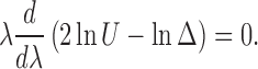 |
It follows that U2/Δ is constant on β, and this must therefore be equal to its value at the starting point x′: U2/Δ = [U2/Δ] = 1, by virtue of Eq. (14.6) and the property [Δ] = 1 of the van Vleck determinant. Because this statement must be true for all geodesics β that emanate from x′, we have found that the unique solution to Eqs. (14.6) and (14.7) is
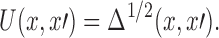 |
14.8 |
We must still consider the remaining terms in Eq. (14.5). The δ± term can be eliminated by demanding that its coefficient vanish when σ = 0. This, however, does not constrain its value away from the light cone, and we thus obtain information about V |σ=0 only. Denoting this by  the restriction of V (x,x′) on the light cone σ (x,x′) = 0 — we have
 |
14.9 |
where we indicate that the right-hand side also must be restricted to the light cone. The first term of Eq. (14.9) can be expressed as  and this equation can be integrated along any null geodesic that generates the null cone σ (x,x′) = 0. For these integrations to be well posed, however, we must provide initial values at x = x′. As we shall now see, these can be inferred from Eq. (14.9) and the fact that V (x, x′) must be smooth at coincidence.
Eqs. (7.4) and (14.8) imply that near coincidence, U (x,x′) admits the expansion
 |
14.10 |
where Rα′β′ is the Ricci tensor at x′ and λ is the affine-parameter distance to x (which can be either on or off the light cone). Differentiation of this relation gives
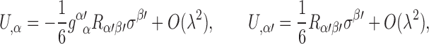 |
14.11 |
and eventually,
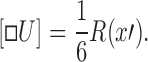 |
14.12 |
Using also  , we find that the coincidence limit of Eq. (14.9) gives
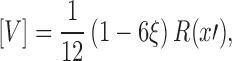 |
14.13 |
and this provides the initial values required for the integration of Eq. (14.9) on the null cone.
Eqs. (14.9) and (14.13) give us a means to construct  , the restriction of V (x, x′) on the null cone σ(x, x′) = 0. These values can then be used as characteristic data for the wave equation
 |
14.14 |
which is obtained by elimination of the θ± term in Eq. (14.5). While this certainly does not constitute a practical method to compute the biscalar V (x,x′), these considerations show that V (x,x′) exists and is unique.
To summarize: We have shown that with U (x, x′) given by Eq. (14.8) and V (x,x′) determined uniquely by the wave equation of Eq. (14.14) and the characteristic data constructed with Eqs. (14.9) and (14.13), the retarded and advanced Green’s functions of Eq. (14.4) do indeed satisfy Eq. (14.3). It should be emphasized that the construction provided in this subsection is restricted to  , the normal convex neighbourhood of the reference point x′.
Reciprocity
We shall now establish the following reciprocity relation between the (globally defined) retarded and advanced Green’s functions:
 |
14.15 |
Before we get to the proof we observe that by virtue of Eq. (14.15), the biscalar V (x,x′) must be symmetric in its arguments:
 |
14.16 |
To go from Eq. (14.15) to Eq. (14.16) we simply note that when  and belongs to I+ (x′), then G+ (x,x′) = V (x,x′) and G−(x′,x) = V (x′,x).
To prove the reciprocity relation we invoke the identities
 |
and
 |
and take their difference. On the left-hand side we have
 |
while the right-hand side gives
 |
. Integrating both sides over a large four-dimensional region that contains both x′ and x ″, we obtain
 |
where ∂V is the boundary of V. Assuming that the Green’s functions fall off sufficiently rapidly at infinity (in the limit ∂V → ∞; this statement imposes some restriction on the spacetime’s asymptotic structure), we have that the left-hand side of the equation evaluates to zero in the limit. This gives us the statement G+ (x ″,x′) = G−(x′,x ″), which is just Eq. (14.15) with x ″ replacing x.
Kirchhoff representation
Suppose that the values for a scalar field Φ(x′) and its normal derivative 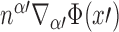 are known on a spacelike hypersurface Σ. Suppose also that the scalar field satisfies the homogeneous wave equation
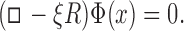 |
14.17 |
then the value of the field at a point x in the future of Σ is given by Kirchhoff’s formula,
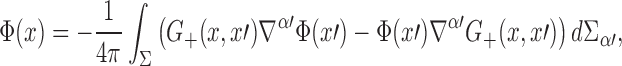 |
14.18 |
where  is the surface element on Σ. If nx′ is the future-directed unit normal, then
  , with dV denoting the invariant volume element on Σ; notice that
  is past directed.
To establish this result we start with the equations
 |
in which x and x′ refer to arbitrary points in spacetime. Taking their difference gives
 |
and this we integrate over a four-dimensional region V that is bounded in the past by the hyper-surface Σ. We suppose that V contains x and we obtain
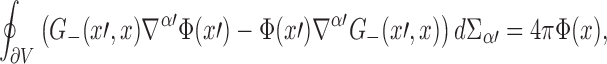 |
where  is the outward-directed surface element on the boundary ∂V. Assuming that the Green’s function falls off sufficiently rapidly into the future, we have that the only contribution to the hypersurface integral is the one that comes from Σ. Since the surface element on Σ points in the direction opposite to the outward-directed surface element on ∂V, we must change the sign of the left-hand side to be consistent with the convention adopted previously. With this change we have
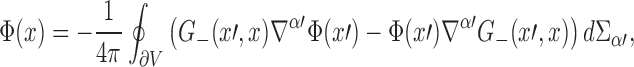 |
which is the same statement as Eq. (14.18) if we take into account the reciprocity relation of Eq. (14.15).
Singular and regular Green’s functions
In Part IV of this review we will compute the retarded field of a moving scalar charge, and we will analyze its singularity structure near the world line; this will be part of our effort to understand the effect of the field on the particle’s motion. The retarded solution to the scalar wave equation is the physically relevant solution because it properly incorporates outgoing-wave boundary conditions at infinity — the advanced solution would come instead with incoming-wave boundary conditions. The retarded field is singular on the world line because a point particle produces a Coulomb field that diverges at the particle’s position. In view of this singular behaviour, it is a subtle matter to describe the field’s action on the particle, and to formulate meaningful equations of motion.
When facing this problem in flat spacetime (recall the discussion of Section 1.3) it is convenient to decompose the retarded Green’s function G+ (x, x′) into a singular Green’s function  and a regular two-point function
  . The singular Green’s function takes its name from the fact that it produces a field with the same singularity structure as the retarded solution: the diverging field near the particle is insensitive to the boundary conditions imposed at infinity. We note also that GS(x,x′) satisfies the same wave equation as the retarded Green’s function (with a Dirac functional as a source), and that by virtue of the reciprocity relations, it is symmetric in its arguments. The regular two-point function, on the other hand, takes its name from the fact that it satisfies the homogeneous wave equation, without the Dirac functional on the right-hand side; it produces a field that is regular on the world line of the moving scalar charge. (We reserve the term “Green’s function” to a two-point function that satisfies the wave equation with a Dirac distribution on the right-hand side; when the source term is absent, the object is called a “two-point function”.)
Because the singular Green’s function is symmetric in its argument, it does not distinguish between past and future, and it produces a field that contains equal amounts of outgoing and incoming radiation — the singular solution describes a standing wave at infinity. Removing GS(x, x′) from the retarded Green’s function will have the effect of removing the singular behaviour of the field without affecting the motion of the particle. The motion is not affected because it is intimately tied to the boundary conditions: If the waves are outgoing, the particle loses energy to the radiation and its motion is affected; if the waves are incoming, the particle gains energy from the radiation and its motion is affected differently. With equal amounts of outgoing and incoming radiation, the particle neither loses nor gains energy and its interaction with the scalar field cannot affect its motion. Thus, subtracting GS(x,x′) from the retarded Green’s function eliminates the singular part of the field without affecting the motion of the scalar charge. The subtraction leaves behind the regular two-point function, which produces a field that is regular on the world line; it is this field that will govern the motion of the particle. The action of this field is well defined, and it properly encodes the outgoing-wave boundary conditions: the particle will lose energy to the radiation.
In this subsection we attempt a decomposition of the curved-spacetime retarded Green’s function into singular and regular pieces. The flat-spacetime relations will have to be amended, however, because of the fact that in a curved spacetime, the advanced Green’s function is generally nonzero when x′ is in the chronological future of x. This implies that the value of the advanced field at x depends on events x′ that will unfold in the future; this dependence would be inherited by the regular field (which acts on the particle and determines its motion) if the naive definition  were to be adopted.
We shall not adopt this definition. Instead, we shall follow Detweiler and Whiting [53] and introduce a singular Green’s function with the properties
- S1: GS(x,x′) satisfies the inhomogeneous scalar wave equation,

14.19 - S2: GS(x,x′) is symmetric in its arguments,

14.20 - S3: GS(x,x′) vanishes if x is in the chronological past or future of x′,

14.21
Properties S1 and S2 ensure that the singular Green’s function will properly reproduce the singular behaviour of the retarded solution without distinguishing between past and future; and as we shall see, property S3 ensures that the support of the regular two-point function will not include the chronological future of x.
The regular two-point function is then defined by
 |
14.22 |
where G+ (x,x′) is the retarded Green’s function. This comes with the properties
- R1: GR(x,x′) satisfies the homogeneous wave equation,
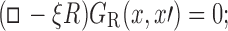
14.23 - R2: GR(x,x′) agrees with the retarded Green’s function if x is in the chronological future of

14.24 - R3: GR(x,x′) vanishes if x is in the chronological past of x′,

14.25
Property R1 follows directly from Eq. (14.22) and property S1 of the singular Green’s function. Properties R2 and R3 follow from S3 and the fact that the retarded Green’s function vanishes if x is in past of x′. The properties of the regular two-point function ensure that the corresponding regular field will be nonsingular at the world line, and will depend only on the past history of the scalar charge.
We must still show that such singular and regular Green’s functions can be constructed. This relies on the existence of a two-point function H (x,x′) that would possess the properties
- H1: H (x,x′) satisfies the homogeneous wave equation,
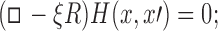
14.26 - H2: H (x,x′) is symmetric in its arguments,
14.27 - H3: H (x,x′) agrees with the retarded Green’s function if x is in the chronological future of

14.28 - H4: H (x,x′) agrees with the advanced Green’s function if x is in the chronological past of

14.29
With a biscalar H (x, x′) satisfying these relations, a singular Green’s function defined by
 |
14.30 |
will satisfy all the properties listed previously: S1 comes as a consequence of H1 and the fact that both the advanced and the retarded Green’s functions are solutions to the inhomogeneous wave equation, S2 follows directly from H2 and the definition of Eq. (14.30), and S3 comes as a consequence of H3, H4 and the properties of the retarded and advanced Green’s functions.
The question is now: does such a function H (x, x′) exist? We will present a plausibility argument for an affirmative answer. Later in this section we will see that H (x,x′) is guaranteed to exist in the local convex neighbourhood of x′, where it is equal to V (x,x′). And in Section 14.6 we will see that there exist particular spacetimes for which H (x, x′) can be defined globally.
To satisfy all of H1–H4 might seem a tall order, but it should be possible. We first note that property H4 is not independent from the rest: it follows from H2, H3, and the reciprocity relation (14.15) satisfied by the retarded and advanced Green’s functions. Let x ∈ I−(x′), so that x′ ∈ I+ (x). Then H (x,x′) = H (x′,x) by H2, and by H3 this is equal to G+ (x′,x). But by the reciprocity relation this is also equal to G−(x,x′), and we have obtained H4. Alternatively, and this shall be our point of view in the next paragraph, we can think of H3 as following from H2 and H4.
Because H (x,x′) satisfies the homogeneous wave equation (property H1), it can be given the Kirkhoff representation of Eq. (14.18): if Σ is a spacelike hypersurface in the past of both x and x′, then
 |
where  is a surface element on Σ. The hypersurface can be partitioned into two segments, Σ−(x′) and Σ − Σ−(x′), with Σ−(x′) denoting the intersection of Σ with I−(x′). To enforce H4 it suffices to choose for H (x,x′) initial data on Σ−(x′) that agree with the initial data for the advanced Green’s function; because both functions satisfy the homogeneous wave equation in I−(x′), the agreement will be preserved in the entire domain of dependence of Σ−(x′). The data on Σ − Σ−(x′) is still free, and it should be possible to choose it so as to make H (x, x′) symmetric. Assuming that this can be done, we see that H2 is enforced and we conclude that the properties H1, H2, H3, and H4 can all be satisfied.
When x is restricted to the normal convex neighbourhood of x′, properties H1–H4 imply that
 |
14.31 |
it should be stressed here that while H (x, x′) is assumed to be defined globally in the entire spacetime, the existence of V (x, x′) is limited to  . With Eqs. (14.4) and (14.30) we find that the singular Green’s function is given explicitly by
 |
14.32 |
in the normal convex neighbourhood. Equation (14.32) shows very clearly that the singular Green’s function does not distinguish between past and future (property S2), and that its support excludes I±(x′), in which θ (σ) = 0 (property S3). From Eq. (14.22) we get an analogous expression for the regular two-point function:
 |
14.33 |
This reveals directly that the regular two-point function coincides with G+(x,x′) in I+(x′), in which θ (σ) = 0 and θ+(−σ) = 1 (property R2), and that its support does not include I−(x′), in which θ (σ) = θ+(−σ) = 0 (property R3).
Example: Cosmological Green’s functions
To illustrate the general theory outlined in the previous subsections we consider here the specific case of a minimally coupled (ξ = 0) scalar field in a cosmological spacetime with metric
 |
14.34 |
where a (η) is the scale factor expressed in terms of conformal time. For concreteness we take the universe to be matter dominated, so that a (η) = Cη2, where is a constant. This spacetime is one of the very few for which Green’s functions can be explicitly constructed. The calculation presented here was first carried out by Burko, Harte, and Poisson [33]; it can be extended to other cosmologies [86].
To solve Green’s equation □G (x,x′) = −4πδ4(x,x′) we first introduce a reduced Green’s function g (x,x′) defined by
 |
14.35 |
Substitution yields
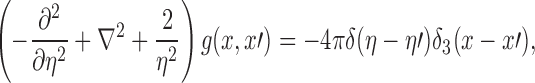 |
14.36 |
where x = (x, y, z) is a vector in three-dimensional flat space, and ∇2 is the Laplacian operator in this space. We next expand g (x, x′) in terms of plane-wave solutions to Laplace’s equation,
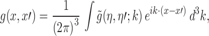 |
14.37 |
and we substitute this back into Eq. (14.36). The result, after also Fourier transforming δ3(x − x′), is an ordinary differential equation for  :
:
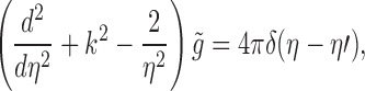 |
14.38 |
where k2 = k · k. To generate the retarded Green’s function we set
 |
14.39 |
in which we indicate that  depends only on the modulus of the vector k. To generate the advanced Green’s function we would set instead
  . The following manipulations will refer specifically to the retarded Green’s function; they are easily adapted to the case of the advanced Green’s function.
Substitution of Eq. (14.39) into Eq. (14.38) reveals that  must satisfy the homogeneous equation
 |
14.40 |
together with the boundary conditions
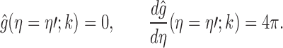 |
14.41 |
Inserting Eq. (14.39) into Eq. (14.37) and integrating over the angular variables associated with the vector k yields
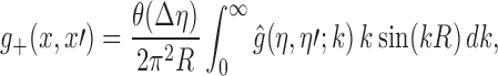 |
14.42 |
where Δη:= η − η′ and R:= |x − x′|.
Eq. (14.40) has cos(k Δη) − (kη)−1 sin(k Δη) and sin(k Δη) + (kη)−1 cos(k Δη) as linearly independent solutions, and  must be given by a linear superposition. The coefficients can be functions of η′, and after imposing Eqs. (14.41) we find that the appropriate combination is
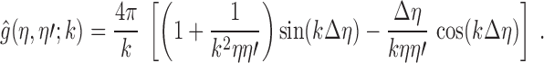 |
14.43 |
Substituting this into Eq. (14.42) and using the identity  yields
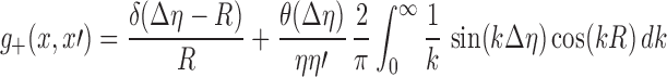 |
after integration by parts. The integral evaluates to θ (Δη − R).
We have arrived at
 |
14.44 |
for our final expression for the retarded Green’s function. The advanced Green’s function is given instead by
 |
14.45 |
The distributions g±(x,x′) are solutions to the reduced Green’s equation of Eq. (14.36). The actual Green’s functions are obtained by substituting Eqs. (14.44) and (14.45) into Eq. (14.35). We note that the support of the retarded Green’s function is given by η − η′ ≥ |x − x′|, while the support of the advanced Green’s function is given by η − η′ ≤ − |x − x′|.
It may be verified that the symmetric two-point function
 |
14.46 |
satisfies all of the properties H1–H4 listed in Section 14.5; it may thus be used to define singular and regular Green’s functions. According to Eq. (14.30) the singular Green’s function is given by
 |
14.47 |
and its support is limited to the interval − |x − x ′| ≤ η − η′ ≤ |x −x′| According to Eq. (14.22) the regular two-point function is given by
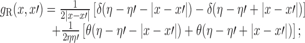 |
14.48 |
its support is given by η − η′ ≥ − |x − x′| and for η − η′ ≥ |x − x′| the regular two-point function agrees with the retarded Green’s function.
As a final observation we note that for this cosmological spacetime, the normal convex neighbourhood of any point x consists of the whole spacetime manifold (which excludes the cosmological singularity at a = 0). The Hadamard construction of the Green’s functions is therefore valid globally, a fact that is immediately revealed by Eqs. (14.44) and (14.45).
Electromagnetic Green’s functions
Equations of electromagnetism
The electromagnetic field tensor Fαβ = ∇αAβ − ∇βAα is expressed in terms of a vector potential Aα. In the Lorenz gauge ∇αAα = 0, the vector potential satisfies the wave equation
 |
15.1 |
where □ = gαβ ∇α ∇β is the wave operator,  the Ricci tensor, and jα a prescribed current density. The wave equation enforces the condition ∇αjα = 0, which expresses charge conservation.
The solution to the wave equation is written as
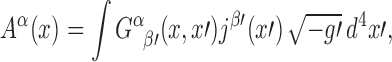 |
15.2 |
in terms of a Green’s function  that satisfies
 |
15.3 |
where  is a parallel propagator and η4(x,x′) an invariant Dirac distribution. The parallel propagator is inserted on the right-hand side of Eq. (15.3) to keep the index structure of the equation consistent from side to side; because
  is distributionally equal to
  , it could have been replaced by either
  . It is easy to check that by virtue of Eq. (15.3), the vector potential of Eq. (15.2) satisfies the wave equation of Eq. (15.1).
We will assume that the retarded Green’s function  , which is nonzero if x is in the causal future of x′, and the advanced Green’s function
  , which is nonzero if x is in the causal past of x′, exist as distributions and can be defined globally in the entire spacetime.
Hadamard construction of the Green’s functions
Assuming throughout this subsection that x is in the normal convex neighbourhood of x′, we make the ansatz
 |
15.4 |
where θ±(−σ), δ±(σ) are the light-cone distributions introduced in Section 13.2, and where  are smooth bitensors.
To conveniently manipulate the Green’s functions we shift σ by a small positive quantity ϵ. The Green’s functions are then recovered by the taking the limit of
 |
as ϵ → 0+. When we substitute this into the left-hand side of Eq. (15.3) and then take the limit, we obtain
 |
after a routine computation similar to the one presented at the beginning of Section 14.2. Comparison with Eq. (15.3) returns: (i) the equations
 |
15.5 |
and
 |
15.6 |
that determine  (ii) the equation
 |
15.7 |
that determines  , the restriction of
  on the light cone σ (x, x′) = 0; and (iii) the wave equation
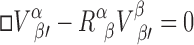 |
15.8 |
that determines  inside the light cone.
Eq. (15.6) can be integrated along the unique geodesic β that links x′ to x. The initial conditions are provided by Eq. (15.5), and if we set  , we find that these equations reduce to Eqs. (14.7) and (14.6), respectively. According to Eq. (14.8), then, we have
 |
15.9 |
which reduces to
 |
15.10 |
near coincidence, with λ denoting the affine-parameter distance between x′ and x. Differentiation of this relation gives
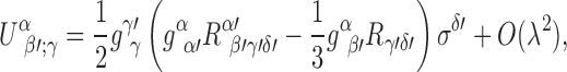 |
15.11 |
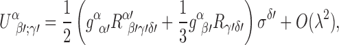 |
15.12 |
and eventually,
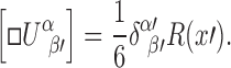 |
15.13 |
Similarly, Eq. (15.7) can be integrated along each null geodesic that generates the null cone σ (x, x′) = 0. The initial values are obtained by taking the coincidence limit of this equation, using Eqs. (15.5), (15.13), and the additional relation  . We arrive at
 |
15.14 |
With the characteristic data obtained by integrating Eq. (15.7), the wave equation of Eq. (15.8) admits a unique solution.
To summarize, the retarded and advanced electromagnetic Green’s functions are given by Eq. (15.4) with  given by Eq. (15.9) and
  determined by Eq. (15.8) and the characteristic data constructed with Eqs. (15.7) and (15.14). It should be emphasized that the construction provided in this subsection is restricted to
  , the normal convex neighbourhood of the reference point x′.
Reciprocity and Kirchhoff representation
Like their scalar counterparts, the (globally defined) electromagnetic Green’s functions satisfy a reciprocity relation, the statement of which is
 |
15.15 |
The derivation of Eq. (15.15) is virtually identical to what was presented in Section 14.3, and we shall not present the details. It suffices to mention that it is based on the identities
 |
and
 |
A direct consequence of the reciprocity relation is
 |
15.16 |
the statement that the bitensor Vαβ′ (x,x′) is symmetric in its indices and arguments.
The Kirchhoff representation for the electromagnetic vector potential is formulated as follows. Suppose that Aα (x) satisfies the homogeneous version of Eq. (15.1) and that initial values Aα′ (x′), nβ′ ∇β′ Aα′ (x′) are specified on a spacelike hypersurface Σ. Then the value of the potential at a point x in the future of Σ is given by
 |
15.17 |
where d Σγ′ = −nγ′dV is a surface element on Σ; nγ′ is the future-directed unit normal and dV is the invariant volume element on the hypersurface. The derivation of Eq. (15.17) is virtually identical to what was presented in Section 14.4.
Relation with scalar Green’s functions
In a spacetime that satisfies the Einstein field equations in vacuum, so that Rαβ = 0 everywhere in the spacetime, the (retarded and advanced) electromagnetic Green’s functions satisfy the identities [54]
 |
15.18 |
where G± are the corresponding scalar Green’s functions.
To prove this we differentiate Eq. (15.3) covariantly with respect to xα and use Eq. (13.3) to express the right-hand side as + 4π∂β′δ4(x,x′). After repeated use of Ricci’s identity to permute the ordering of the covariant derivatives on the left-hand side, we arrive at the equation
 |
15.19 |
all terms involving the Riemann tensor disappear by virtue of the fact that the spacetime is Ricciflat. Because Eq. (15.19) is also the differential equation satisfied by G;β′, and because the solutions are chosen to satisfy the same boundary conditions, we have established the validity of Eq. (15.18).
Singular and regular Green’s functions
We shall now construct singular and regular Green’s functions for the electromagnetic field. The treatment here parallels closely what was presented in Section 14.5, and the reader is referred to that section for a more complete discussion.
We begin by introducing the bitensor  with properties
- H1:
 satisfies the homogeneous wave equation,
15.20 - H2:
 is symmetric in its indices and arguments,
15.21 - H3:
 agrees with the retarded Green’s function if x is in the chronological future of x′,
15.22 - H4:
 agrees with the advanced Green’s function if x is in the chronological past of x′,
15.23
It is easy to prove that property H4 follows from H2, H3, and the reciprocity relation (15.15) satisfied by the retarded and advanced Green’s functions. That such a bitensor exists can be argued along the same lines as those presented in Section 14.5.
Equipped with the bitensor  we define the singular Green’s function to be
 |
15.24 |
This comes with the properties
- S1:
 satisfies the inhomogeneous wave equation,
15.25 - S2:
 is symmetric in its indices and arguments,
15.26 - S3:
 vanishes if x is in the chronological past or future of x′,
15.27
These can be established as consequences of H1–H4 and the properties of the retarded and advanced Green’s functions.
The regular two-point function is then defined by
 |
15.28 |
and it comes with the properties
- R1:
 satisfies the homogeneous wave equation,
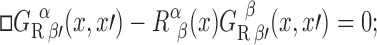
15.29 - R2:
 agrees with the retarded Green’s function if x is in the chronological future of x′,
15.30 - R3:
 vanishes if x is in the chronological past of x′,
15.31
Those follow immediately from S1—S3 and the properties of the retarded Green’s function.
When x is restricted to the normal convex neighbourhood of x′, we have the explicit relations
 |
15.32 |
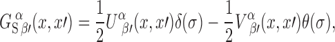 |
15.33 |
 |
15.34 |
From these we see clearly that the singular Green’s function does not distinguish between past and future (property S2), and that its support excludes I±(x′) (property S3). We see also that the regular two-point function coincides with  in I+ (x′) (property R2), and that its support does not include I−(x′) (property R3).
Gravitational Green’s functions
Equations of linearized gravity
We are given a background spacetime for which the metric gαβ satisfies the Einstein field equations in vacuum. We then perturb the metric from gαβ to
 |
16.1 |
The metric perturbation hαβ is assumed to be small, and when working out the Einstein field equations to be satisfied by the new metric gαβ, we work consistently to first order in hαβ. To simplify the expressions we use the trace-reversed potentials γαβ defined by
 |
16.2 |
and we impose the Lorenz gauge condition,
 |
16.3 |
In this equation, and in all others below, indices are raised and lowered with the background metric gαβ. Similarly, the connection involved in Eq. (16.3), and in all other equations below, is the one that is compatible with the background metric. If is the perturbing energy-momentum tensor, then by virtue of the linearized Einstein field equations the perturbation field obeys the wave equation
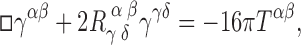 |
16.4 |
in which □ = gαβ ∇α ∇β is the wave operator and Rγαδβ the Riemann tensor. In first-order perturbation theory, the energy-momentum tensor must be conserved in the background spacetime:  .
.
The solution to the wave equation is written as
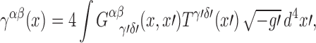 |
16.5 |
in terms of a Green’s function  that satisfies [161]
 |
16.6 |
where  is a parallel propagator and δ4(x,x′) an invariant Dirac functional. The parallel propagators are inserted on the right-hand side of Eq. (16.6) to keep the index structure of the equation consistent from side to side; in particular, both sides of the equation are symmetric in α and β, and in γ′ and δ′. It is easy to check that by virtue of Eq. (16.6), the perturbation field of Eq. (16.5) satisfies the wave equation of Eq. (16.4). Once γαβ is known, the metric perturbation can be reconstructed from the relation
  .
.
We will assume that the retarded Green’s function  , which is nonzero if x is in the causal future of x′, and the advanced Green’s function
  , which is nonzero if x is in the causal past of x′, exist as distributions and can be defined globally in the entire background spacetime.
Hadamard construction of the Green’s functions
Assuming throughout this subsection that is in the normal convex neighbourhood of x′, we make the ansatz
 |
16.7 |
where θ±(−σ), δ±(σ) are the light-cone distributions introduced in Section 13.2, and where  are smooth bitensors.
To conveniently manipulate the Green’s functions we shift σ by a small positive quantity ϵ. The Green’s functions are then recovered by the taking the limit of
 |
as ϵ → 0+. When we substitute this into the left-hand side of Eq. (16.6) and then take the limit, we obtain
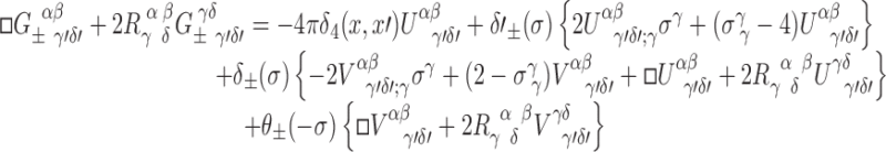 |
after a routine computation similar to the one presented at the beginning of Section 14.2. Comparison with Eq. (16.6) returns: (i) the equations
 |
16.8 |
and
 |
16.9 |
that determine  (ii) the equation
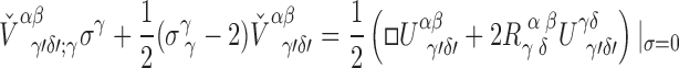 |
16.10 |
that determine  , the restriction of
  on the light cone σ (x, x′) = 0; and (iii) the wave equation
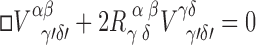 |
16.11 |
that determines  inside the light cone.
Eq. (16.9) can be integrated along the unique geodesic β that links x′ to x. The initial conditions are provided by Eq. (16.8), and if we set 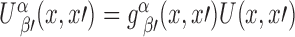 , we find that these equations reduce to Eqs. (14.7) and (14.6), respectively. According to Eq. (14.8), then, we have
 |
16.12 |
which reduces to
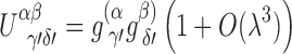 |
16.13 |
near coincidence, with λ denoting the affine-parameter distance between x′ and x; there is no term of order λ2 because by assumption, the background Ricci tensor vanishes at x′ (as it does in the entire spacetime). Differentiation of this relation gives
 |
16.14 |
 |
16.15 |
and eventually,
 |
16.16 |
this last result follows from the fact that  is antisymmetric in the last pair of indices.
Similarly, Eq. (16.10) can be integrated along each null geodesic that generates the null cone σ (x, x′) = 0. The initial values are obtained by taking the coincidence limit of this equation, using Eqs. (16.8), (16.16), and the additional relation  . We arrive at
 |
16.17 |
With the characteristic data obtained by integrating Eq. (16.10), the wave equation of Eq. (16.11) admits a unique solution.
To summarize, the retarded and advanced gravitational Green’s functions are given by Eq. (16.7) with  given by Eq. (16.12) and
  determined by Eq. (16.11) and the characteristic data constructed with Eqs. (16.10) and (16.17). It should be emphasized that the construction provided in this subsection is restricted to
  , the normal convex neighbourhood of the reference point x′.
Reciprocity and Kirchhoff representation
The (globally defined) gravitational Green’s functions satisfy the reciprocity relation
 |
16.18 |
The derivation of this result is virtually identical to what was presented in Sections 14.3 and 15.3. A direct consequence of the reciprocity relation is the statement
 |
16.19 |
The Kirchhoff representation for the trace-reversed gravitational perturbation γαβ is formulated as follows. Suppose that γαβ (x) satisfies the homogeneous version of Eq. (16.4) and that initial values  are specified on a spacelike hypersurface Σ. Then the value of the perturbation field at a point x in the future of Σ is given by
 |
16.20 |
where dΣϵ′= − nϵ′dV is a surface element on Σ; nϵ′ is the future-directed unit normal and dV is the invariant volume element on the hypersurface. The derivation of Eq. (16.20) is virtually identical to what was presented in Sections 14.4 and 15.3.
Relation with electromagnetic and scalar Green’s functions
In a spacetime that satisfies the Einstein field equations in vacuum, so that Rαβ = 0 everywhere in the spacetime, the (retarded and advanced) gravitational Green’s functions satisfy the identities [144]
 |
16.21 |
and
 |
16.22 |
where  are the corresponding electromagnetic Green’s functions, and G± the corresponding scalar Green’s functions.
To prove Eq. (16.21) we differentiate Eq. (16.6) covariantly with respect to xβ, use Eq. (13.3) to work on the right-hand side, and invoke Ricci’s identity to permute the ordering of the covariant derivatives on the left-hand side. After simplification and involvement of the Ricci-flat condition (which, together with the Bianchi identities, implies that  , we arrive at the equation
 |
16.23 |
Because this is also the differential equation satisfied by  , and because the solutions are chosen to satisfy the same boundary conditions, we have established the validity of Eq. (16.21).
The identity of Eq. (16.22) follows simply from the fact that  and gαβG satisfy the same tensorial wave equation in a Ricci-flat spacetime.
Singular and regular Green’s functions
We shall now construct singular and regular Green’s functions for the linearized gravitational field. The treatment here parallels closely what was presented in Sections 14.5 and 15.5.
We begin by introducing the bitensor  with properties
- H1:
 satisfies the homogeneous wave equation,
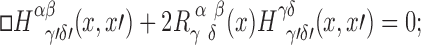
16.24 - H2:
 is symmetric in its indices and arguments,
16.25 - H3:
 agrees with the retarded Green’s function if x is in the chronological future of x′,
16.26 - H4:
 agrees with the advanced Green’s function if x is in the chronological past of x′,
16.27
It is easy to prove that property H4 follows from H2, H3, and the reciprocity relation (16.18) satisfied by the retarded and advanced Green’s functions. That such a bitensor exists can be argued along the same lines as those presented in Section 14.5.
Equipped with  we define the singular Green’s function to be
 |
16.28 |
This comes with the properties
- S1:
 satisfies the inhomogeneous wave equation,
16.29 - S2:
 is symmetric in its indices and arguments,
16.30 - S3:
 vanishes if x is in the chronological past or future of x′,
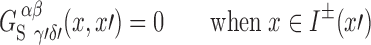
16.31
These can be established as consequences of H1–H4 and the properties of the retarded and advanced Green’s functions.
The regular two-point function is then defined by
 |
16.32 |
and it comes with the properties
- R1:
 satisfies the homogeneous wave equation,
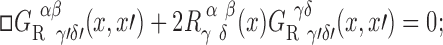
16.33 - R2:
 agrees with the retarded Green’s function if x is in the chronological future of x′,
16.34 - R3:
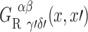 vanishes if x is in the chronological past of x′,
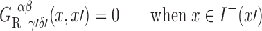
16.35
Those follow immediately from S1–S3 and the properties of the retarded Green’s function.
When x is restricted to the normal convex neighbourhood of x′, we have the explicit relations
 |
16.36 |
 |
16.37 |
 |
16.38 |
From these we see clearly that the singular Green’s function does not distinguish between past and future (property S2), and that its support excludes I±(x′) (property S3). We see also that the regular two-point function coincides with  in I+(x′) (property R2), and that its support does not include I−(x′) (property R3).
Part IV: Motion of Point Particles
Motion of a scalar charge
Dynamics of a point scalar charge
A point particle carries a scalar charge q and moves on a world line γ described by relations zμ(λ), in which λ is an arbitrary parameter. The particle generates a scalar potential Φ(x) and a field Φα(x) := ∇αΦ(x). The dynamics of the entire system is governed by the action
 |
17.1 |
where Sfield is an action functional for a free scalar field in a spacetime with metric gαβ, Sparticle is the action of a free particle moving on a world line γ in this spacetime, and Sinteraction is an interaction term that couples the field to the particle.
The field action is given by
 |
17.2 |
where the integration is over all of spacetime; the field is coupled to the Ricci scalar R by an arbitrary constant ξ. The particle action is
 |
17.3 |
where m0 is the bare mass of the particle and  is the differential of proper time along the world line; we use an overdot on zμ(λ) to indicate differentiation with respect to the parameter λ. Finally, the interaction term is given by
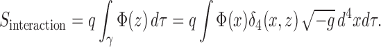 |
17.4 |
Notice that both Sparticle and Sinteraction are invariant under a reparameterization λ → λ′(λ) of the world line.
Demanding that the total action be stationary under a variation δΦ(x) of the field configuration yields the wave equation
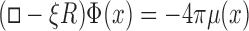 |
17.5 |
for the scalar potential, with a charge density μ(x) defined by
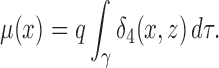 |
17.6 |
These equations determine the field Φα(x) once the motion of the scalar charge is specified. On the other hand, demanding that the total action be stationary under a variation δzμ(λ) of the world line yields the equations of motion
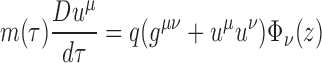 |
17.7 |
for the scalar charge. We have here adopted τ as the parameter on the world line, and introduced the four-velocity uμ(τ) := dzμ/dτ. The dynamical mass that appears in Eq. (17.7) is defined by m(τ) := m0 − qΦ(z), which can also be expressed in differential form as
 |
17.8 |
It should be clear that Eqs. (17.7) and (17.8) are valid only in a formal sense, because the scalar potential obtained from Eqs. (17.5) and (17.6) diverges on the world line. Before we can make sense of these equations we have to analyze the field’s singularity structure near the world line.
Retarded potential near the world line
The retarded solution to Eq. (17.5) is 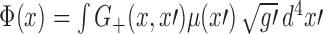 , where G+(x, x′) is the retarded Green’s function introduced in Section 14. After substitution of Eq. (17.6) we obtain
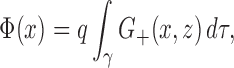 |
17.9 |
in which z(τ) gives the description of the world line γ. Because the retarded Green’s function is defined globally in the entire spacetime, Eq. (17.9) applies to any field point x.
We now specialize Eq. (17.9) to a point x near the world line; see Figure 9. We let  be the normal convex neighbourhood of this point, and we assume that the world line traverses
  . Let τ< be the value of the proper-time parameter at which γ enters
  from the past, and let τ> be its value when the world line leaves
  . Then Eq. (17.9) can be broken up into the three integrals
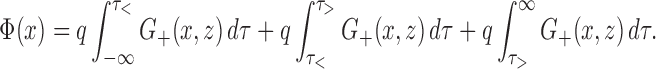 |
The third integration vanishes because x is then in the past of z(τ), and G+(x, z) = 0. For the second integration, x is the normal convex neighbourhood of z(τ), and the retarded Green’s function can be expressed in the Hadamard form produced in Section 14.2. This gives
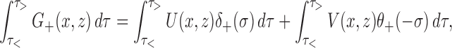 |
and to evaluate this we refer back to Section 10 and let x′ := z(u) be the retarded point associated with x; these points are related by σ(x, x′) = 0 and  is the retarded distance between x and the world line. We resume the index convention of Section 10: to tensors at x we assign indices α, β, etc.; to tensors at x′ we assign indices α′, β′, etc.; and to tensors at a generic point z(τ) on the world line we assign indices μ, ν, etc.
Figure 9.

The region within the dashed boundary represents the normal convex neighbourhood of the point x. The world line γ enters the neighbourhood at proper time τ< and exits at proper time τ>. Also shown are the retarded point z(u) and the advanced point z(v).
To perform the first integration we change variables from τ to σ, noticing that σ increases as z(τ) passes through x′. The change of σ on the world line is given by dσ:= σ(x, z + dz) − σ(x, z) = σμuμ dτ, and we find that the first integral evaluates to U(x, z)/(σμuμ) with z identified with x′. The second integration is cut off at τ = u by the step function, and we obtain our final expression for the retarded potential of a point scalar charge:
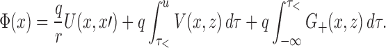 |
17.10 |
This expression applies to a point x sufficiently close to the world line that there exists a nonempty intersection between  and γ.
Field of a scalar charge in retarded coordinates
When we differentiate the potential of Eq. (17.10) we must keep in mind that a variation in x induces a variation in x′ because the new points x + δx and x′ + δx′ must also be linked by a null geodesic — you may refer back to Section 10.2 for a detailed discussion. This means, for example, that the total variation of U(x, x′) is  . The gradient of the scalar potential is therefore given by
 |
17.11 |
where the “tail integral” is defined by
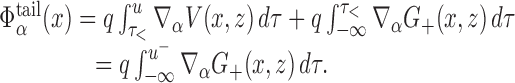 |
17.12 |
In the second form of the definition we integrate ∇αG+(x, z) from τ = −∞ to almost τ = u, but we cut the integration short at τ = u− := u − 0+ to avoid the singular behaviour of the retarded Green’s function at σ = 0. This limiting procedure gives rise to the first form of the definition, with the advantage that the integral need not be broken up into contributions that refer to  and its complement, respectively.
We shall now expand Φα(x) in powers of r, and express the results in terms of the retarded coordinates (u, r, Ωa) introduced in Section 10. It will be convenient to decompose Φα(x) in the tetrad  that is obtained by parallel transport of
  on the null geodesic that links x to x′ := z(u); this construction is detailed in Section 10. The expansion relies on Eq. (10.29) for ∂αu, Eq. (10.31) for ∂αr, and we shall need
 |
17.13 |
which follows from Eq. (14.10) and the relation  first encountered in Eq. (10.7); recall that
 |
are frame components of the Ricci tensor evaluated at x′. We shall also need the expansions
 |
17.14 |
and
 |
17.15 |
which follow from Eqs. (14.11); recall from Eq. (10.4) that the parallel propagator can be expressed as 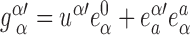 . And finally, we shall need
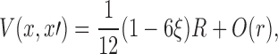 |
17.16 |
a relation that was first established in Eq. (14.13); here R:= R(u) is the Ricci scalar evaluated at x′.
Collecting all these results gives
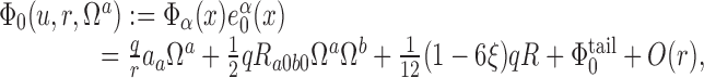 |
17.17 |
 |
17.18 |
where  are the frame components of the acceleration vector,
 |
are frame components of the Riemann tensor evaluated at x′, and
 |
17.19 |
are the frame components of the tail integral evaluated at x′. Equations (17.17) and (17.18) show clearly that Φα(x) is singular on the world line: the field diverges as r−2 when r → 0, and many of the terms that stay bounded in the limit depend on Ωa and therefore possess a directional ambiguity at r = 0.
Field of a scalar charge in Fermi normal coordinates
The gradient of the scalar potential can also be expressed in the Fermi normal coordinates of Section 9. To effect this translation we make x:= z(t) the new reference point on the world line. We resume here the notation of Section 11 and assign indices  to tensors at
  . The Fermi normal coordinates are denoted (t, s, ωa), and we let
  be the tetrad at x that is obtained by parallel transport of
  on the spacelike geodesic that links x to
  .
.
Our first task is to decompose Φα(x) in the tetrad  , thereby defining
  and
and 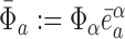 . For this purpose we use Eqs. (11.7), (11.8), (17.17), and (17.18) to obtain
 |
and
 |
where all frame components are still evaluated at x′, except for  and
and  which are evaluated at
  .
.
We must still translate these results into the Fermi normal coordinates (t, s, ωa). For this we involve Eqs. (11.4), (11.5), and (11.6), from which we deduce, for example,
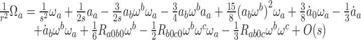 |
and
 |
in which all frame components (on the right-hand side of these relations) are now evaluated at  ; to obtain the second relation we expressed aa(u) as aa(t) − sȧa(t) + O(s2) since according to Eq. (11.4), u = t − s + O(s2).
Collecting these results yields
 |
17.20 |
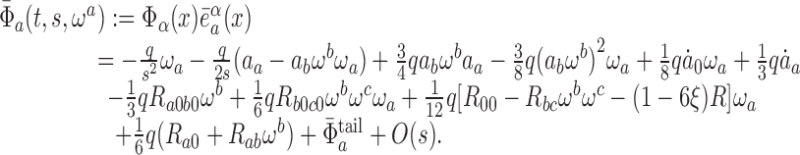 |
17.21 |
In these expressions, 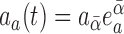 are the frame components of the acceleration vector evaluated at
 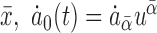 and
and 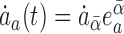 are frame components of its covariant derivative,
  are frame components of the Riemann tensor evaluated at
  ,
,
 |
are frame components of the Ricci tensor, and R(t) is the Ricci scalar evaluated at  . Finally, we have that
 |
17.22 |
are the frame components of the tail integral — see Eq. (17.12) — evaluated at  .
.
We shall now compute the averages of  and
and  over S(t, s), a two-surface of constant t and s; these will represent the mean value of the field at a fixed proper distance away from the world line, as measured in a reference frame that is momentarily comoving with the particle. The two-surface is charted by angles θA (A = 1, 2) and it is described, in the Fermi normal coordinates, by the parametric relations
  ; a canonical choice of parameterization is ωa = (sin θ cos ϕ, sin θ sin ϕ, cos θ). Introducing the transformation matrices
  , we find from Eq. (9.16) that the induced metric on S(t, s) is given by
 |
17.23 |
where  is the metric of the unit two-sphere, and where
  depends on t and the angles θA. From this we infer that the element of surface area is given by
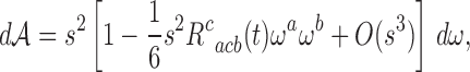 |
17.24 |
where  is an element of solid angle — in the canonical parameterization, dω = sin θ dθdϕ. Integration of Eq. (17.24) produces the total surface area of S(t, s), and
  .
.
The averaged fields are defined by
 |
17.25 |
where the quantities to be integrated are scalar functions of the Fermi normal coordinates. The results
 |
17.26 |
are easy to establish, and we obtain
 |
17.27 |
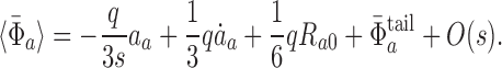 |
17.28 |
The averaged field is still singular on the world line. Regardless, we shall take the formal limit s → 0 of the expressions displayed in Eqs. (17.27) and (17.28). In the limit the tetrad  reduces to
  ), and we can reconstruct the field at
  by invoking the completeness relations
 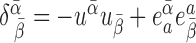 . We thus obtain
 |
17.29 |
where the tail integral can be copied from Eq. (17.12),
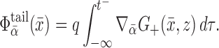 |
17.30 |
The tensors appearing in Eq. (17.29) all refer to  , which now stands for an arbitrary point on the world line γ.
Singular and regular fields
The singular potential
 |
17.31 |
is the (unphysical) solution to Eqs. (17.5) and (17.6) that is obtained by adopting the singular Green’s function of Eq. (14.30) instead of the retarded Green’s function. As we shall see, the resulting singular field  reproduces the singular behaviour of the retarded solution; the difference,
 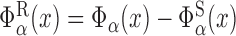 , is smooth on the world line.
To evaluate the integral of Eq. (17.31) we assume once more that x is sufficiently close to γ that the world line traverses  ; refer back to Figure 9. As before we let τ< and τ> be the values of the proper-time parameter at which γ enters and leaves
  , respectively. Then Eq. (17.31) can be broken up into the three integrals
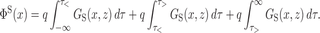 |
The first integration vanishes because x is then in the chronological future of z(τ), and Gs(x, z) = 0 by Eq. (14.21). Similarly, the third integration vanishes because x is then in the chronological past of z(τ). For the second integration, x is the normal convex neighbourhood of z(τ), the singular Green’s function can be expressed in the Hadamard form of Eq. (14.32), and we have
 |
To evaluate these we re-introduce the retarded point x′ := z(u) and let x″:= z(v) be the advanced point associated with x; we recall from Section 11.4 that these points are related by σ(x, x″) = 0 and that  is the advanced distance between x and the world line.
To perform the first integration we change variables from τ to σ, noticing that σ increases as z(τ) passes through x′; the integral evaluates to U(x, x′)/r. We do the same for the second integration, but we notice now that σ decreases as z(τ) passes through x″; the integral evaluates to U(x, x″)/radv. The third integration is restricted to the interval u ≤ τ ≤ v by the step function, and we obtain our final expression for the singular potential of a point scalar charge:
 |
17.32 |
We observe that ΦS (x) depends on the state of motion of the scalar charge between the retarded time u and the advanced time v; contrary to what was found in Section 17.2 for the retarded potential, there is no dependence on the particle’s remote past.
We use the techniques of Section 17.3 to differentiate the potential of Eq. (17.32). We find
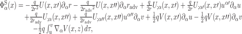 |
17.33 |
and we would like to express this as an expansion in powers of r. For this we shall rely on results already established in Section 17.3, as well as additional expansions that will involve the advanced point x″. Those we develop now.
We recall first that a relation between retarded and advanced times was worked out in Eq. (11.12), that an expression for the advanced distance was displayed in Eq. (11.13), and that Eqs. (11.14) and (11.15) give expansions for ∂αv and ∂αradv, respectively.
To derive an expansion for U(x, x″) we follow the general method of Section 11.4 and define a function U(τ) := U(x, z(τ)) of the proper-time parameter on γ. We have that
 |
where overdots indicate differentiation with respect to τ, and where Δ′ := v − u. The leading term U(u) := U(x, x′) was worked out in Eq. (17.13), and the derivatives of U(τ) are given by
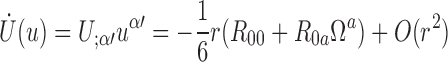 |
and
 |
according to Eqs. (17.15) and (14.11). Combining these results together with Eq. (11.12) for Δ′ gives
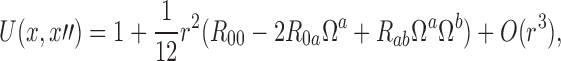 |
17.34 |
which should be compared with Eq. (17.13). It should be emphasized that in Eq. (17.34) and all equations below, the frame components of the Ricci tensor are evaluated at the retarded point x′ := z(u), and not at the advanced point. The preceding computation gives us also an expansion for  . This becomes
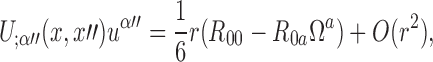 |
17.35 |
which should be compared with Eq. (17.15).
We proceed similarly to derive an expansion for U;α(x, x″). Here we introduce the functions Uα(τ) := U;α(x, z(τ)) and express U;α(x, x″) as  . The leading term Uα(u) := U;α(x, x′) was computed in Eq. (17.14), and
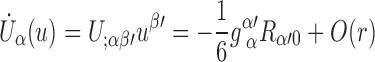 |
follows from Eq. (14.11). Combining these results together with Eq. (11.12) for Δ′ gives
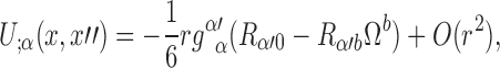 |
17.36 |
and this should be compared with Eq. (17.14).
The last expansion we shall need is
 |
17.37 |
which follows at once from Eq. (17.16) and the fact that V(x, x″) − V(x, x′) = O(r); the Ricci scalar is evaluated at the retarded point x′.
It is now a straightforward (but tedious) matter to substitute these expansions (all of them!) into Eq. (17.33) and obtain the projections of the singular field  in the same tetrad
  that was employed in Section 17.3. This gives
 |
17.38 |
 |
17.39 |
in which all frame components are evaluated at the retarded point x′ := z(u). Comparison of these expressions with Eqs. (17.17) and (17.18) reveals that the retarded and singular fields share the same singularity structure.
The difference between the retarded field of Eqs. (17.17), (17.18) and the singular field of Eqs. (17.38), (17.39) defines the regular field  . Its frame components are
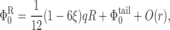 |
17.40 |
 |
17.41 |
and we see that  is a regular vector field on the world line. There is therefore no obstacle in evaluating the regular field directly at x = x′, where the tetrad
  becomes
  . Reconstructing the field at x′ from its frame components, we obtain
 |
17.42 |
where the tail term can be copied from Eq. (17.12),
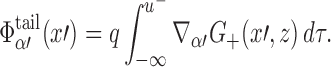 |
17.43 |
The tensors appearing in Eq. (17.42) all refer to the retarded point x′ := z(u), which now stands for an arbitrary point on the world line γ.
Equations of motion
The retarded field Φα(x) of a point scalar charge is singular on the world line, and this behaviour makes it difficult to understand how the field is supposed to act on the particle and affect its motion. The field’s singularity structure was analyzed in Sections 17.3 and 17.4, and in Section 17.5 it was shown to originate from the singular field  ; the regular field
  was then shown to be regular on the world line.
To make sense of the retarded field’s action on the particle we temporarily model the scalar charge not as a point particle, but as a small hollow shell that appears spherical when observed in a reference frame that is momentarily comoving with the particle; the shell’s radius is s0 in Fermi normal coordinates, and it is independent of the angles contained in the unit vector ωa. The net force acting at proper time τ on this hollow shell is the average of qΦα(τ, s0, ωa) over the surface of the shell. Assuming that the field on the shell is equal to the field of a point particle evaluated at s = s0, and ignoring terms that disappear in the limit s0 → 0, we obtain from Eq. (17.29)
 |
17.44 |
where
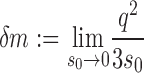 |
17.45 |
is formally a divergent quantity and
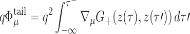 |
17.46 |
is the tail part of the force; all tensors in Eq. (17.44) are evaluated at an arbitrary point z(τ) on the world line.
Substituting Eqs. (17.44) and (17.46) into Eq. (17.7) gives rise to the equations of motion
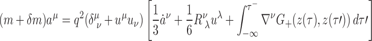 |
17.47 |
for the scalar charge, with m:= m0 − qΦ(z) denoting the (also formally divergent) dynamical mass of the particle. We see that m and δm combine in Eq. (17.47) to form the particle’s observed mass mobs, which is taken to be finite and to give a true measure of the particle’s inertia. All diverging quantities have thus disappeared into the process of mass renormalization. Substituting Eqs. (17.44) and (17.46) into Eq. (17.8), in which we replace m by mobs = m + δm, returns an expression for the rate of change of the observed mass,
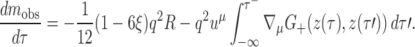 |
17.48 |
That the observed mass is not conserved is a remarkable property of the dynamics of a scalar charge in a curved spacetime. Physically, this corresponds to the fact that in a spacetime with a time-dependent metric, a scalar charge radiates monopole waves and the radiated energy comes at the expense of the particle’s inertial mass.
We must confess that the derivation of the equations of motion outlined above returns the wrong expression for the self-energy of a spherical shell of scalar charge. We obtained δm = q2/(3s0), while the correct expression is δm = q2/(2s0); we are wrong by a factor of 2/3. We believe that this discrepancy originates in a previously stated assumption, that the field on the shell (as produced by the shell itself) is equal to the field of a point particle evaluated at s = s0. We believe that this assumption is in fact wrong, and that a calculation of the field actually produced by a spherical shell would return the correct expression for δm. We also believe, however, that except for the diverging terms that determine δm, the difference between the shell’s field and the particle’s field should vanish in the limit s0 → 0. Our conclusion is therefore that while our expression for δm is admittedly incorrect, the statement of the equations of motion is reliable.
Apart from the term proportional to δm, the averaged field of Eq. (17.44) has exactly the same form as the regular field of Eq. (17.42), which we re-express as
 |
17.49 |
The force acting on the point particle can therefore be thought of as originating from the regular field, while the singular field simply contributes to the particle’s inertia. After mass renormalization, Eqs. (17.47) and (17.48) are equivalent to the statements
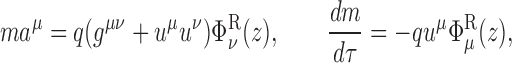 |
17.50 |
where we have dropped the superfluous label “obs” on the particle’s observed mass. Another argument in support of the claim that the motion of the particle should be affected by the regular field only was presented in Section 14.5.
The equations of motion displayed in Eqs. (17.47) and (17.48) are third-order differential equations for the functions zμ(τ). It is well known that such a system of equations admits many unphysical solutions, such as runaway situations in which the particle’s acceleration increases exponentially with τ, even in the absence of any external force [56, 101]. And indeed, our equations of motion do not yet incorporate an external force which presumably is mostly responsible for the particle’s acceleration. Both defects can be cured in one stroke. We shall take the point of view, the only admissible one in a classical treatment, that a point particle is merely an idealization for an extended object whose internal structure — the details of its charge distribution — can be considered to be irrelevant. This view automatically implies that our equations are meant to provide only an approximate description of the object’s motion. It can then be shown [112, 70] that within the context of this approximation, it is consistent to replace, on the right-hand side of the equations of motion, any occurrence of the acceleration vector by  , where
  is the external force acting on the particle. Because
  is a prescribed quantity, differentiation of the external force does not produce higher derivatives of the functions zμ(τ), and the equations of motion are properly of the second order.
We shall strengthen this conclusion in Part V of the review, when we consider the motion of an extended body in a curved external spacetime. While the discussion there will concern the gravitational self-force, many of the lessons learned in Part V apply just as well to the case of a scalar (or electric) charge. And the main lesson is this: It is natural — indeed it is an imperative — to view an equation of motion such as Eq. (17.47) as an expansion of the acceleration in powers of q2, and it is therefore appropriate — indeed imperative — to insert the zeroth-order expression for ȧν within the term of order q2. The resulting expression for the acceleration is then valid up to correction terms of order q4. Omitting these error terms, we shall write, in final analysis, the equations of motion in the form
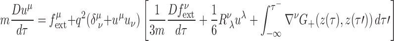 |
17.51 |
and
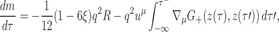 |
17.52 |
where m denotes the observed inertial mass of the scalar charge, and where all tensors are evaluated at z(τ). We recall that the tail integration must be cut short at τ′ = τ− := τ − 0+ to avoid the singular behaviour of the retarded Green’s function at coincidence; this procedure was justified at the beginning of Section 17.3. Equations (17.51) and (17.52) were first derived by Theodore C. Quinn in 2000 [149]. In his paper Quinn also establishes that the total work done by the scalar self-force matches the amount of energy radiated away by the particle.
Motion of an electric charge
Dynamics of a point electric charge
A point particle carries an electric charge e and moves on a world line γ described by relations zμ(λ), in which λ is an arbitrary parameter. The particle generates a vector potential Aα(x) and an electromagnetic field Fαβ(x) = ∇αAβ − ∇βAα. The dynamics of the entire system is governed by the action
 |
18.1 |
where Sfield is an action functional for a free electromagnetic field in a spacetime with metric gαβ, Sparticle is the action of a free particle moving on a world line γ in this spacetime, and Sinteraction is an interaction term that couples the field to the particle.
The field action is given by
 |
18.2 |
where the integration is over all of spacetime. The particle action is
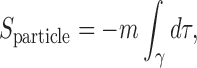 |
18.3 |
where m is the bare mass of the particle and  is the differential of proper time along the world line; we use an overdot to indicate differentiation with respect to the parameter λ. Finally, the interaction term is given by
 |
18.4 |
Notice that both Sparticle and Sinteraction are invariant under a reparameterization λ → λ′(λ) of the world line.
Demanding that the total action be stationary under a variation δAα(x) of the vector potential yields Maxwell’s equations
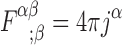 |
18.5 |
with a current density jα(x) defined by
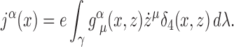 |
18.6 |
These equations determine the electromagnetic field Fαβ once the motion of the electric charge is specified. On the other hand, demanding that the total action be stationary under a variation δzμ(λ) of the world line yields the equations of motion
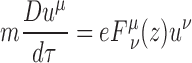 |
18.7 |
for the electric charge. We have adopted τ as the parameter on the world line, and introduced the four-velocity uμ(τ) := dzμ/dτ.
The electromagnetic field Fαβ is invariant under a gauge transformation of the form Aα → Aα + ∇αΛ, in which Λ(x) is an arbitrary scalar function. This function can always be chosen so that the vector potential satisfies the Lorenz gauge condition,
 |
18.8 |
Under this condition the Maxwell equations of Eq. (18.5) reduce to a wave equation for the vector potential,
 |
18.9 |
where D = gαβ∇α∇β is the wave operator and  is the Ricci tensor. Having adopted τ as the parameter on the world line, we can re-express the current density of Eq. (18.6) as
 |
18.10 |
and we shall use Eqs. (18.9) and (18.10) to determine the electromagnetic field of a point electric charge. The motion of the particle is in principle determined by Eq. (18.7), but because the vector potential obtained from Eq. (18.9) is singular on the world line, these equations have only formal validity. Before we can make sense of them we will have to analyze the field’s singularity structure near the world line. The calculations to be carried out parallel closely those presented in Section 17 for the case of a scalar charge; the details will therefore be kept to a minimum and the reader is referred to Section 17 for additional information.
Retarded potential near the world line
The retarded solution to Eq. (18.9) is  , where
  is the retarded Green’s function introduced in Section 15. After substitution of Eq. (18.10) we obtain
 |
18.11 |
in which zμ(τ) gives the description of the world line γ and uμ(τ) = dzμ/dτ. Because the retarded Green’s function is defined globally in the entire spacetime, Eq. (18.11) applies to any field point x.
We now specialize Eq. (18.11) to a point x close to the world line. We let  be the normal convex neighbourhood of this point, and we assume that the world line traverses
  ; refer back to Figure 9. As in Section 17.2 we let τ< and τ> be the values of the proper-time parameter at which γ enters and leaves
  , respectively. Then Eq. (18.11) can be expressed as
 |
The third integration vanishes because x is then in the past of z(τ), and  . For the second integration, x is the normal convex neighbourhood of z(τ), and the retarded Green’s function can be expressed in the Hadamard form produced in Section 15.2. This gives
 |
and to evaluate this we let x′ := z(u) be the retarded point associated with x; these points are related by σ(x, x′) = 0 and 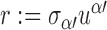 is the retarded distance between x and the world line. To perform the first integration we change variables from τ to σ, noticing that σ increases as z(τ) passes through x′; the integral evaluates to
  . The second integration is cut off at τ = u by the step function, and we obtain our final expression for the vector potential of a point electric charge:
 |
18.12 |
This expression applies to a point x sufficiently close to the world line that there exists a nonempty intersection between  and γ.
Electromagnetic field in retarded coordinates
When we differentiate the vector potential of Eq. (18.12) we must keep in mind that a variation in x induces a variation in x′, because the new points x + δx and x′ + δx′ must also be linked by a null geodesic. Taking this into account, we find that the gradient of the vector potential is given by
 |
18.13 |
where the “tail integral” is defined by
 |
18.14 |
The second form of the definition, in which we integrate the gradient of the retarded Green’s function from τ = −∞ to τ = u− := u − 0+ to avoid the singular behaviour of the retarded Green’s function at σ = 0, is equivalent to the first form.
We shall now expand Fαβ = ∇αAβ − ∇βAα in powers of r, and express the result in terms of the retarded coordinates (u, r, Ωa) introduced in Section 10. It will be convenient to decompose the electromagnetic field in the tetrad  that is obtained by parallel transport of
  on the null geodesic that links x to x′ := z(u); this construction is detailed in Section 10. We recall from Eq. (10.4) that the parallel propagator can be expressed as
 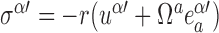 . The expansion relies on Eq. (10.29) for ∂αu, Eq. (10.31) for ∂αr, and we shall need
 |
18.15 |
which follows from Eq. (15.10) and the relation  first encountered in Eq. (10.7). We shall also need the expansions
 |
18.16 |
and
 |
18.17 |
that follow from Eqs. (15.10)–(15.12). And finally, we shall need
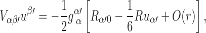 |
18.18 |
a relation that was first established in Eq. (15.14).
Collecting all these results gives
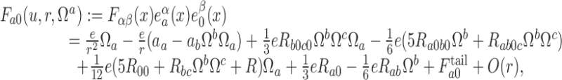 |
18.19 |
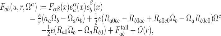 |
18.20 |
where
 |
18.21 |
are the frame components of the tail integral; this is obtained from Eq. (18.14) evaluated at x′:
 |
18.22 |
It should be emphasized that in Eqs. (18.19) and (18.20), all frame components are evaluated at the retarded point x′ := z(u) associated with x; for example,  . It is clear from these equations that the electromagnetic field Fαβ(x) is singular on the world line.
Electromagnetic field in Fermi normal coordinates
We now wish to express the electromagnetic field in the Fermi normal coordinates of Section 9; as before those will be denoted (t, s, ωa). The translation will be carried out as in Section 17.4, and we will decompose the field in the tetrad  that is obtained by parallel transport of
  on the spacelike geodesic that links x to the simultaneous point x:= z(t).
Our first task is to decompose Fαβ(x) in the tetrad  , thereby defining
  and
and  . For this purpose we use Eqs. (11.7), (11.8), (18.19), and (18.20) to obtain
 |
and
 |
where all frame components are still evaluated at x′, except for
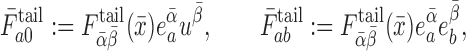 |
which are evaluated at  .
.
We must still translate these results into the Fermi normal coordinates (t, s, ωa). For this we involve Eqs. (11.4), (11.5), and (11.6), and we recycle some computations that were first carried out in Section 17.4. After some algebra, we arrive at
 |
18.23 |
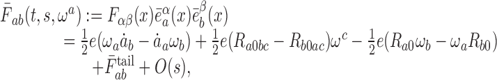 |
18.24 |
where all frame components are now evaluated at x:= z(t); for example,  .
.
Our next task is to compute the averages of  and
and  over S(t, s), a two-surface of constant t and s. These are defined by
 |
18.25 |
where  is the element of surface area on S(t, s), and
  . Using the methods developed in Section 17.4, we find
 |
18.26 |
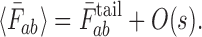 |
18.27 |
The averaged field is singular on the world line, but we nevertheless take the formal limit s → 0 of the expressions displayed in Eqs. (18.26) and (18.27). In the limit the tetrad  becomes
  , and we can easily reconstruct the field at
  from its frame components. We thus obtain
 |
18.28 |
where the tail term can be copied from Eq. (18.22),
 |
18.29 |
The tensors appearing in Eq. (18.28) all refer to  , which now stands for an arbitrary point on the world line γ.
Singular and regular fields
The singular vector potential
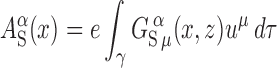 |
18.30 |
is the (unphysical) solution to Eqs. (18.9) and (18.10) that is obtained by adopting the singular Green’s function of Eq. (15.24) instead of the retarded Green’s function. We will see that the singular field  reproduces the singular behaviour of the retarded solution, and that the difference,
  , is smooth on the world line.
To evaluate the integral of Eq. (18.30) we assume once more that x is sufficiently close to γ that the world line traverses  ; refer back to Figure 9. As before we let τ< and τ> be the values of the proper-time parameter at which γ enters and leaves
  , respectively. Then Eq. (18.30) becomes
 |
The first integration vanishes because x is then in the chronological future of z(τ), and  by Eq. (15.27). Similarly, the third integration vanishes because x is then in the chronological past of z(τ). For the second integration, x is the normal convex neighbourhood of z(τ), the singular Green’s function can be expressed in the Hadamard form of Eq. (15.33), and we have
 |
To evaluate these we let x′ := z(u) and x″:= z(v) be the retarded and advanced points associated with x, respectively. To perform the first integration we change variables from τ to σ, noticing that σ increases as z(τ) passes through x′; the integral evaluates to  . We do the same for the second integration, but we notice now that σ decreases as z(τ) passes through x″; the integral evaluates to
 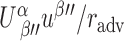 , where
 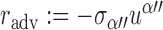 is the advanced distance between x and the world line. The third integration is restricted to the interval u ≤ τ ≤ v by the step function, and we obtain the expression
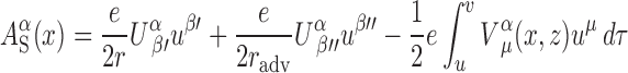 |
18.31 |
for the singular vector potential.
Differentiation of Eq. (18.31) yields
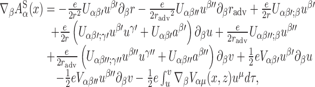 |
18.32 |
and we would like to express this as an expansion in powers of r. For this we will rely on results already established in Section 18.3, as well as additional expansions that will involve the advanced point x″. We recall that a relation between retarded and advanced times was worked out in Eq. (11.12), that an expression for the advanced distance was displayed in Eq. (11.13), and that Eqs. (11.14) and (11.15) give expansions for ∂αv and ∂αradv, respectively.
To derive an expansion for  we follow the general method of Section 11.4 and introduce the functions Uα(τ) := Uαμ(x, z)uμ. We have that
 |
where overdots indicate differentiation with respect to τ, and Δ′ := v − u. The leading term  was worked out in Eq. (18.15), and the derivatives of Uα(τ) are given by
 |
and
 |
according to Eqs. (18.17) and (15.12). Combining these results together with Eq. (11.12) for Δ′ gives
 |
18.33 |
which should be compared with Eq. (18.15). It should be emphasized that in Eq. (18.33) and all equations below, all frame components are evaluated at the retarded point x′, and not at the advanced point. The preceding computation gives us also an expansion for
 |
which becomes
 |
18.34 |
and which should be compared with Eq. (18.17).
We proceed similarly to derive an expansion for  . Here we introduce the functions
  and express
  as
as  . The leading term
  was computed in Eq. (18.16), and
 |
follows from Eq. (15.11). Combining these results together with Eq. (11.12) for Δ′ gives
 |
18.35 |
and this should be compared with Eq. (18.16). The last expansion we shall need is
 |
18.36 |
which follows at once from Eq. (18.18).
It is now a straightforward (but still tedious) matter to substitute these expansions into Eq. (18.32) to obtain the projections of the singular electromagnetic field 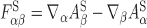 in the same tetrad
  that was employed in Section 18.3. This gives
 |
18.37 |
 |
18.38 |
in which all frame components are evaluated at the retarded point x′. Comparison of these expressions with Eqs. (18.19) and (18.20) reveals that the retarded and singular fields share the same singularity structure.
The difference between the retarded field of Eqs. (18.19), (18.20) and the singular field of Eqs. (18.37), (18.38) defines the regular field  . Its tetrad components are
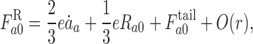 |
18.39 |
 |
18.40 |
and we see that  is a regular tensor field on the world line. There is therefore no obstacle in evaluating the regular field directly at x = x′, where the tetrad
  becomes
  . Reconstructing the field at x′ from its frame components, we obtain
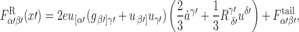 |
18.41 |
where the tail term can be copied from Eq. (18.22),
 |
18.42 |
The tensors appearing in Eq. (18.41) all refer to the retarded point x′ := z(u), which now stands for an arbitrary point on the world line γ.
Equations of motion
The retarded field Fαβ of a point electric charge is singular on the world line, and this behaviour makes it difficult to understand how the field is supposed to act on the particle and exert a force. The field’s singularity structure was analyzed in Sections 18.3 and 18.4, and in Section 18.5 it was shown to originate from the singular field  ; the regular field
 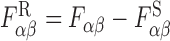 was then shown to be regular on the world line.
To make sense of the retarded field’s action on the particle we follow the discussion of Section 17.6 and temporarily picture the electric charge as a spherical hollow shell; the shell’s radius is s0 in Fermi normal coordinates, and it is independent of the angles contained in the unit vector ωa. The net force acting at proper time τ on this shell is proportional to the average of Fαβ(τ, s0, ωa) over the shell’s surface. Assuming that the field on the shell is equal to the field of a point particle evaluated at s = s0, and ignoring terms that disappear in the limit s0 → 0, we obtain from Eq. (18.28)
 |
18.43 |
where
 |
18.44 |
is formally a divergent quantity and
 |
18.45 |
is the tail part of the force; all tensors in Eq. (18.43) are evaluated at an arbitrary point z(τ) on the world line.
Substituting Eqs. (18.43) and (18.45) into Eq. (18.7) gives rise to the equations of motion
 |
18.46 |
for the electric charge, with m denoting the (also formally divergent) bare mass of the particle. We see that m and δm combine in Eq. (18.46) to form the particle’s observed mass mobs, which is finite and gives a true measure of the particle’s inertia. All diverging quantities have thus disappeared into the procedure of mass renormalization.
We must confess, as we did in the case of the scalar self-force, that the derivation of the equations of motion outlined above returns the wrong expression for the self-energy of a spherical shell of electric charge. We obtained δm = 2e2/(3s0), while the correct expression is δm = e2/(2s0); we are wrong by a factor of 4/3. As before we believe that this discrepancy originates in a previously stated assumption, that the field on the shell (as produced by the shell itself) is equal to the field of a point particle evaluated at s = s0. We believe that this assumption is in fact wrong, and that a calculation of the field actually produced by a spherical shell would return the correct expression for δm. We also believe, however, that except for the diverging terms that determine δm, the difference between the shell’s field and the particle’s field should vanish in the limit s0 → 0. Our conclusion is therefore that while our expression for δm is admittedly incorrect, the statement of the equations of motion is reliable.
Apart from the term proportional to δm, the averaged force of Eq. (18.43) has exactly the same form as the force that arises from the regular field of Eq. (18.41), which we express as
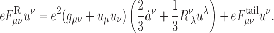 |
18.47 |
The force acting on the point particle can therefore be thought of as originating from the regular field, while the singular field simply contributes to the particle’s inertia. After mass renormalization, Eq. (18.46) is equivalent to the statement
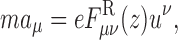 |
18.48 |
where we have dropped the superfluous label “obs” on the particle’s observed mass.
For the final expression of the equations of motion we follow the discussion of Section 17.6 and allow an external force  to act on the particle, and we replace, on the right-hand side of the equations, the acceleration vector by
  . This produces
 |
18.49 |
in which m denotes the observed inertial mass of the electric charge and all tensors are evaluated at z(τ), the current position of the particle on the world line; the primed indices in the tail integral refer to the point z(τ′), which represents a prior position. We recall that the integration must be cut short at τ′ = τ− := τ − 0+ to avoid the singular behaviour of the retarded Green’s function at coincidence; this procedure was justified at the beginning of Section 18.3. Equation (18.49) was first derived (without the Ricci-tensor term) by Bryce S. DeWitt and Robert W. Brehme in 1960 [54], and then corrected by J.M. Hobbs in 1968 [95]. An alternative derivation was produced by Theodore C. Quinn and Robert M. Wald in 1997 [150]. In a subsequent publication [151], Quinn and Wald proved that the total work done by the electromagnetic self-force matches the energy radiated away by the particle.
Motion of a point mass
Dynamics of a point mass
Introduction
In this section we consider the motion of a point particle of mass m subjected to its own gravitational field in addition to an external field. The particle moves on a world line γ in a curved spacetime whose background metric gαβ is assumed to be a vacuum solution to the Einstein field equations. We shall suppose that m is small, so that the perturbation hαβ created by the particle can also be considered to be small. In the final analysis we shall find that hαβ obeys a linear wave equation in the background spacetime, and this linearization of the field equations will allow us to fit the problem of determining the motion of a point mass within the general framework developed in Sections 17 and 18. We shall find that γ is not a geodesic of the background spacetime because hαβ acts on the particle and produces an acceleration proportional to m; the motion is geodesic in the test-mass limit only.
While we can make the problem fit within the general framework, it is important to understand that the problem of motion in gravitation is conceptually very different from the versions encountered previously in the case of a scalar or electromagnetic field. In these cases, the field equations satisfied by the scalar potential Φ or the vector potential Aα are fundamentally linear; in general relativity the field equations satisfied by hαβ are fundamentally nonlinear, and this makes a major impact on the formulation of the problem. (In all cases the coupled problem of determining the field and the motion of the particle is nonlinear.) Another difference resides with the fact that in the previous cases, the field equations and the law of motion could be formulated independently of each other (because the action functional could be varied independently with respect to the field and the world line); in general relativity the law of motion follows from energy-momentum conservation, which is itself a consequence of the field equations.
The dynamics of a point mass in general relativity must therefore be formulated with care. We shall describe a formal approach to this problem, based on the fiction that the spacetime of a point particle can be constructed exactly in general relativity. (This is indeed a fiction, because it is known [80] that the metric of a point particle, as described by a Dirac distribution on a world line, is much too singular to be defined as a distribution in spacetime. The construction, however, makes distributional sense at the level of the linearized theory.) The outcome of this approach will be an approximate formulation of the equations of motion that relies on a linearization of the field equations, and which turns out to be closely analogous to the scalar and electromagnetic cases encountered previously. We shall put the motion of a small mass on a much sounder foundation in Part V, where we take m to be a (small) extended body instead of a point particle.
Exact formulation
Let a point particle of mass m move on a world line γ in a curved spacetime with metric gαβ. This is the exact metric of the perturbed spacetime, and it depends on m as well as all other relevant parameters. At a later stage of the discussion gαβ will be expressed as sum of a “background” part gαβ that is independent of m, and a “perturbation” part hαβ that contains the dependence on m. The world line is described by relations zμ(λ) in which λ is an arbitrary parameter — this will later be identified with proper time τ in the background spacetime. We use sans-serif symbols to denote tensors that refer to the perturbed spacetime; tensors in the background spacetime will be denoted, as usual, by italic symbols.
The particle’s action functional is
 |
19.1 |
where żμ = dzμ/dλ is tangent to the world line and the metric is evaluated at z. We assume that the particle provides the only source of matter in the spacetime — an explanation will be provided below — so that the Einstein field equations take the form of
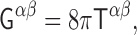 |
19.2 |
where Gαβ is the Einstein tensor constructed from gαβ and
 |
19.3 |
is the particle’s energy-momentum tensor, obtained by functional differentiation of Sparticle with respect to gαβ(x); the parallel propagators appear naturally by expressing gμν as  .
.
On a formal level the metric gαβ is obtained by solving the Einstein field equations, and the world line is determined by the equations of energy-momentum conservation, which follow from the field equations. From Eqs. (5.14), (13.3), and (19.3) we obtain
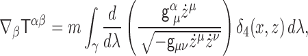 |
and additional manipulations reduce this to
 |
19.4 |
where Dżμ/dλ is the covariant acceleration and k is a scalar field on the world line. Energy-momentum conservation therefore produces the geodesic equation
 |
19.5 |
and
 |
19.6 |
measures the failure of λ to be an affine parameter on the geodesic γ.
Decomposition into background and perturbation
At this stage we begin treating m as a small quantity, and we write
 |
19.7 |
with gαβ denoting the m → 0 limit of the metric gαβ, and hαβ containing the dependence on m. We shall refer to gαβ as the “metric of the background spacetime” and to hαβ as the “perturbation” produced by the particle. We insist, however, that no approximation is introduced at this stage; the perturbation hαβ is the exact difference between the exact metric gαβ and the background metric gαβ. Below we shall use the background metric to lower and raise indices.
We introduce the tensor field
 |
19.8 |
as the exact difference between  , the connection compatible with the exact metric gαβ, and
  , the connection compatible with the background metric gαβ. A covariant differentiation indicated by; α will refer to
  , while a covariant differentiation indicated by ∇α will continue to refer to
  .
.
We express the exact Einstein tensor as
 |
19.9 |
where Gαβ is the Einstein tensor of the background spacetime, which is assumed to vanish. The second term δGαβ is the linearized Einstein operator defined by
 |
19.10 |
where □γαβ := gγδηαβ;γδ is the wave operator in the background spacetime, and
 |
19.11 |
is the “trace-reversed” metric perturbation (with all indices raised with the background metric). The third term ΔGαβ contains the remaining nonlinear pieces that are excluded from δGαβ.
Field equations and conservation statement
The exact Einstein field equations can be expressed as
 |
19.12 |
where the effective energy-momentum tensor is defined by
 |
19.13 |
Because δGαβ satisfies the Bianchi-like identities δGαβ ;β, the effective energy-momentum tensor is conserved in the background spacetime:
 |
19.14 |
This statement is equivalent to ∇β⊺αβ = 0, as can be inferred from the equations  , and the definition of
  . Equation (19.14), in turn, is equivalent to Eq. (19.5), which states that the motion of the point particle is geodesic in the perturbed spacetime.
Integration of the field equations
Eq. (19.12) expresses the full and exact content of Einstein’s field equations. It is written in such a way that the left-hand side is linear in the perturbation hαβ, while the right-hand side contains all nonlinear terms. It may be viewed formally as a set of linear differential equations for hαβ with a specified source term  . This equation is of mixed hyperbolic-elliptic type, and as such it is a poor starting point for the selection of retarded solutions that enforce a strict causal link between the source and the field. This inadequacy, however, can be remedied by imposing the Lorenz gauge condition
 |
19.15 |
which converts δGαβ into a strictly hyperbolic differential operator. In this gauge the field equations become
 |
19.16 |
This is a tensorial wave equation formulated in the background spacetime, and while the left-hand side is manifestly linear in hαβ, the right-hand side continues to incorporate all nonlinear terms. Equations (19.15) and (19.16) still express the full content of the exact field equations.
A formal solution to Eq. (19.16) is
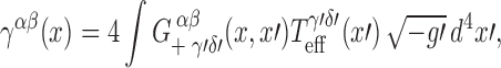 |
19.17 |
where 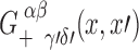 is the retarded Green’s function introduced in Section 16. With the help of Eq. (16.21), it is easy to show that
 |
19.18 |
follows directly from Eq. (19.17);  is the electromagnetic Green’s function introduced in Section 15. This equation indicates that the Lorenz gauge condition is automatically enforced when the conservation equation
  is imposed. Conversely, Eq. (19.18) implies that
 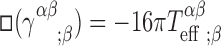 , which indicates that imposition of
  automatically enforces the conservation equation. There is a one-to-one correspondence between the conservation equation and the Lorenz gauge condition.
The split of the Einstein field equations into a wave equation and a gauge condition directly tied to the conservation of the effective energy-momentum tensor is a most powerful tool, because it allows us to disentangle the problems of obtaining hαβ and determining the motion of the particle. This comes about because the wave equation can be solved first, independently of the gauge condition, for a particle moving on an arbitrary world line γ; the world line is determined next, by imposing the Lorenz gauge condition on the solution to the wave equation. More precisely stated, the source term  for the wave equation can be evaluated for any world line γ, without demanding that the effective energy-momentum tensor be conserved, and without demanding that γ be a geodesic of the perturbed spacetime. Solving the wave equation then returns hαβ[γ] as a functional of the arbitrary world line, and the metric is not yet fully specified. Because imposing the Lorenz gauge condition is equivalent to imposing conservation of the effective energy-momentum tensor, inserting hαβ[γ] within Eq. (19.15) finally determines γ, and forces it to be a geodesic of the perturbed spacetime. At this stage the full set of Einstein field equations is accounted for, and the metric is fully specified as a tensor field in spacetime. The split of the field equations into a wave equation and a gauge condition is key to the formulation of the gravitational self-force; in this specific context the Lorenz gauge is conferred a preferred status among all choices of gauge.
An important question to be addressed is how the wave equation is to be integrated. A method of principle, based on the assumed smallness of m and hαβ, is suggested by post-Minkowskian theory [180, 26]. One proceeds by iterations. In the first iterative stage, one fixes γ and substitutes  within
  ; evaluation of the integral in Eq. (19.17) returns the first-order approximation
 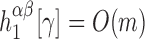 for the perturbation. In the second stage
  is inserted within
  and Eq. (19.17) returns the second-order approximation
  for the perturbation. Assuming that this procedure can be repeated at will and produces an adequate asymptotic series for the exact perturbation, the iterations are stopped when the nth-order approximation
  is deemed to be sufficiently accurate. The world line is then determined, to order mn, by subjecting the approximated field to the Lorenz gauge condition. It is to be noted that the procedure necessarily produces an approximation of the field, and an approximation of the motion, because the number of iterations is necessarily finite. This is the only source of approximation in our formulation of the dynamics of a point mass.
Equations of motion
Conservation of energy-momentum implies Eq. (19.5), which states that the motion of the point mass is geodesic in the perturbed spacetime. The equation is expressed in terms of the exact connection  , and with the help of Eq. (19.8) it can be re-written in terms of the background connection
  . We get
  , where the left-hand side is the covariant acceleration in the background spacetime, and k is given by Eq. (19.6). At this stage the arbitrary parameter λ can be identified with proper time τ in the background spacetime. With this choice the equations of motion become
 |
19.19 |
where uμ := dzμ/dτ is the velocity vector in the background spacetime, aμ := Duμ/dτ the covariant acceleration, and
 |
19.20 |
Eq. (19.19) is an exact statement of the equations of motion. It expresses the fact that while the motion is geodesic in the perturbed spacetime, it may be viewed as accelerated motion in the background spacetime. Because hαβ is calculated as an expansion in powers of m, the acceleration also is eventually obtained as an expansion in powers of m. Here, in keeping with the preceding sections, we will use order-reduction to make that expansion well-behaved; in Part V of the review, we will formulate the expansion more clearly as part of more systematic approach.
Implementation to first order in m
While our formulation of the dynamics of a point mass is in principle exact, any practical implementation will rely on an approximation method. As we saw previously, the most immediate source of approximation concerns the number of iterations involved in the integration of the wave equation. Here we perform a single iteration and obtain the perturbation hαβ and the equations of motion to first order in the mass m.
In a first iteration of the wave equation we fix γ and set ΔGαβ = 0, ⊺αβ = Tαβ, where
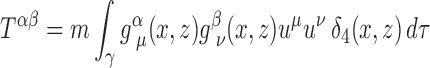 |
19.21 |
is the particle’s energy-momentum tensor in the background spacetime. This implies that  , and Eq. (19.16) becomes
 |
19.22 |
Its solution is
 |
19.23 |
and from this we obtain hαβ. Equation (19.8) gives rise to  , and from Eq. (19.20) we obtain
  ; we can discard the second term because it is clear that the acceleration will be of order m. Inserting these results within Eq. (19.19), we obtain
 |
19.24 |
We express this in the equivalent form
 |
19.25 |
to emphasize the fact that the acceleration is orthogonal to the velocity vector.
It should be clear that Eq. (19.25) is valid only in a formal sense, because the potentials obtained from Eqs. (19.23) diverge on the world line. To make sense of these equations we will proceed as in Sections 17 and 18 with a careful analysis of the field’s singularity structure; regularization will produce a well-defined version of Eq. (19.25). Our formulation of the dynamics of a point mass makes it clear that a proper implementation requires that the wave equation of Eq. (19.22) and the equations of motion of Eq. (19.25) be integrated simultaneously, in a self-consistent manner.
Failure of a strictly linearized formulation
In the preceding discussion we started off with an exact formulation of the problem of motion for a small mass m in a background spacetime with metric gαβ, but eventually boiled it down to an implementation accurate to first order in m. Would it not be simpler and more expedient to formulate the problem directly to first order? The answer is a resounding no: By doing so we would be driven toward a grave inconsistency; the nonlinear formulation is absolutely necessary if one wishes to contemplate a self-consistent integration of Eqs. (19.22) and (19.25).
A strictly linearized formulation of the problem would be based on the field equations δGαβ = 8πTαβ, where Tαβ is the energy-momentum tensor of Eq. (19.21). The Bianchi-like identities δGαβ;β = 0 dictate that Tαβ must be conserved in the background spacetime, and a calculation identical to the one leading to Eq. (19.5) would reveal that the particle’s motion must be geodesic in the background spacetime. In the strictly linearized formulation, therefore, the gravitational potentials of Eq. (19.23) must be sourced by a particle moving on a geodesic, and there is no opportunity for these potentials to exert a self-force. To get the self-force, one must provide a formulation that extends beyond linear order. To be sure, one could persist in adopting the linearized formulation and “save the phenomenon” by relaxing the conservation equation. In practice this could be done by adopting the solutions of Eq. (19.23), demanding that the motion be geodesic in the perturbed spacetime, and relaxing the linearized gauge condition to γαβ;β = O(m2). While this prescription would produce the correct answer, it is largely ad hoc and does not come with a clear justification. Our exact formulation provides much more control, at least in a formal sense. We shall do even better in Part V.
An alternative formulation of the problem provided by Gralla and Wald [83] avoids the inconsistency by refraining from performing a self-consistent integration of Eqs. (19.22) and (19.25). Instead of an expansion of the acceleration in powers of m, their approach is based on an expansion of the world line itself, and it returns the equations of motion for a deviation vector which describes the offset of the true world line relative to a reference geodesic. While this approach is mathematically sound, it eventually breaks down as the deviation vector becomes large, and it does not provide a justification of the self-consistent treatment of the equations.
The difference between the Gralla-Wald approach and a self-consistent one is the difference between a regular expansion and a general one. In a regular expansion, all dependence on a small quantity m is expanded in powers:
 |
19.26 |
In a general expansion, on the other hand, the functions  are allowed to retain some dependence on the small quantity:
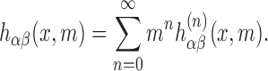 |
19.27 |
Put simply, the goal of a general expansion is to expand only part of a function’s dependence on a small quantity, while holding fixed some specific dependence that captures one or more of the function’s essential features. In the self-consistent expansion that we advocate here, our iterative solution returns
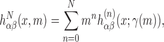 |
19.28 |
in which the functional dependence on the world line γ incorporates a dependence on the expansion parameter m. We deliberately introduce this functional dependence on a mass-dependent world line in order to maintain a meaningful and accurate description of the particle’s motion. Although the regular expansion can be retrieved by further expanding the dependence within γ(m), the reverse statement does not hold: the general expansion cannot be justified on the basis of the regular one. The notion of a general expansion is at the core of singular perturbation theory [63, 96, 109, 111, 178, 145]. We shall return to these issues in our treatment of asymptotically small bodies, and in particular, in Section 22.5 below.
Vacuum background spacetime
To conclude this subsection we should explain why it is desirable to restrict our discussion to spacetimes that contain no matter except for the point particle. Suppose, in contradiction with this assumption, that the background spacetime contains a distribution of matter around which the particle is moving. (The corresponding vacuum situation has the particle moving around a black hole. Notice that we are still assuming that the particle moves in a region of spacetime in which there is no matter; the issue is whether we can allow for a distribution of matter somewhere else.) Suppose also that the matter distribution is described by a collection of matter fields Ψ. Then the field equations satisfied by the matter have the schematic form E[Ψ; g] = 0, and the background metric is determined by the Einstein field equations G[g] = 8πM[Ψ; g], in which M[Ψ; g] stands for the matter’s energy-momentum tensor. We now insert the point particle in the spacetime, and recognize that this displaces the background solution (Ψ, g) to a new solution (Ψ + δΨ, g + δg). The perturbations are determined by the coupled set of equations E[Ψ + δΨ; g + δg] = 0 and G[g + δg] = 8πM[Ψ + δΨ; g + δg] + 8πT[g]. After linearization these take the form of
 |
where EΨ, Eg, MΦ, and Mg are suitable differential operators acting on the perturbations. This is a coupled set of partial differential equations for the perturbations δΨ and δg. These equations are linear, but they are much more difficult to deal with than the single equation for δg that was obtained in the vacuum case. And although it is still possible to solve the coupled set of equations via a Green’s function technique, the degree of difficulty is such that we will not attempt this here. We shall, therefore, continue to restrict our attention to the case of a point particle moving in a vacuum (globally Ricci-flat) background spacetime.
Retarded potentials near the world line
Going back to Eq. (19.23), we have that the gravitational potentials associated with a point particle of mass m moving on world line γ are given by
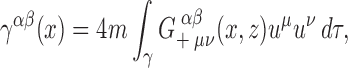 |
19.29 |
up to corrections of order m; here zμ(τ) gives the description of the world line, uμ = dzμ/dτ is the velocity vector, and  is the retarded Green’s function introduced in Section 16. Because the retarded Green’s function is defined globally in the entire background spacetime, Eq. (19.29) describes the gravitational perturbation created by the particle at any point x in that spacetime.
For a more concrete expression we take x to be in a neighbourhood of the world line. The manipulations that follow are very close to those performed in Section 17.2 for the case of a scalar charge, and in Section 18.2 for the case of an electric charge. Because these manipulations are by now familiar, it will be sufficient here to present only the main steps. There are two important simplifications that occur in the case of a massive particle. First, it is clear that
 |
19.30 |
and we will take the liberty of performing a pre-emptive order-reduction by dropping all terms involving the acceleration vector when computing γαβ and γαβ;γ to first order in m; otherwise we would arrive at an equation for the acceleration that would include an antidamping term  [92, 93, 150]. Second, because we take gαβ to be a solution to the vacuum field equations, we are also allowed to set
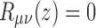 |
19.31 |
in our computations.
With the understanding that x is close to the world line (refer back to Figure 9), we substitute the Hadamard construction of Eq. (16.7) into Eq. (19.29) and integrate over the portion of γ that is contained in  . The result is
 |
19.32 |
in which primed indices refer to the retarded point x′ := z(u) associated with  is the retarded distance from x′ to x, and τ< is the proper time at which γ enters
  from the past.
In the following subsections we shall refer to γαβ(x) as the gravitational potentials at x produced by a particle of mass m moving on the world line γ, and to γαβ;γ(x) as the gravitational field at x. To compute this is our next task.
Gravitational field in retarded coordinates
Keeping in mind that x′ and x are related by σ(x, x′) = 0, a straightforward computation reveals that the covariant derivatives of the gravitational potentials are given by
 |
19.33 |
where the “tail integral” is defined by
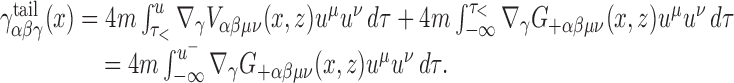 |
19.34 |
The second form of the definition, in which the integration is cut short at τ = u− := u − 0+ to avoid the singular behaviour of the retarded Green’s function at σ = 0, is equivalent to the first form.
We wish to express γαβ;γ(x) in the retarded coordinates of Section 10, as an expansion in powers of r. For this purpose we decompose the field in the tetrad  that is obtained by parallel transport of
  on the null geodesic that links x to x′; this construction is detailed in Section 10. We recall from Eq. (10.4) that the parallel propagator can be expressed as
  . The expansion relies on Eq. (10.29) for ∂γu and Eq. (10.31) for ∂γr, both simplified by setting aa = 0. We shall also need
 |
19.35 |
which follows from Eq. (16.13),
 |
19.36 |
 |
19.37 |
which follow from Eqs. (16.14) and (16.15), respectively, as well as the relation  first encountered in Eq. (10.7). And finally, we shall need
 |
19.38 |
which follows from Eq. (16.17).
Making these substitutions in Eq. (19.3) and projecting against various members of the tetrad gives
 |
19.39 |
 |
19.40 |
 |
19.41 |
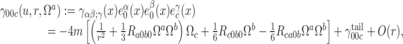 |
19.42 |
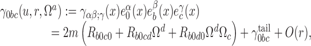 |
19.43 |
 |
19.44 |
where, for example, 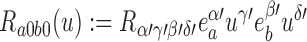 are frame components of the Riemann tensor evaluated at x′ := z(u). We have also introduced the frame components of the tail part of the gravitational field, which are obtained from Eq. (19.34) evaluated at x′ instead of x; for example,
  . We may note here that while γ00c is the only component of the gravitational field that diverges when r → 0, the other components are nevertheless singular because of their dependence on the unit vector Ωa; the only exception is γab0, which is regular.
Gravitational field in Fermi normal coordinates
The translation of the results contained in Eqs. (19.39)–(19.44) into the Fermi normal coordinates of Section 9 proceeds as in Sections 17.4 and 18.4, but is simplified by setting aa = ȧ0 = ȧa = 0 in Eqs. (11.7), (11.8), (11.4), (11.5), and (11.6) that relate the Fermi normal coordinates (t, s, ωa) to the retarded coordinates. We recall that the Fermi normal coordinates refer to a point x:= z(t) on the world line that is linked to x by a spacelike geodesic that intersects γ orthogonally.
The translated results are
 |
19.45 |
 |
19.46 |
 |
19.47 |
 |
19.48 |
 |
19.49 |
 |
19.50 |
where all frame components are now evaluated at  instead of x′.
It is then a simple matter to average these results over a two-surface of constant t and s. Using the area element of Eq. (17.24) and definitions analogous to those of Eq. (17.25), we obtain
 |
19.51 |
 |
19.52 |
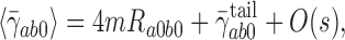 |
19.53 |
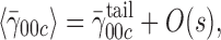 |
19.54 |
 |
19.55 |
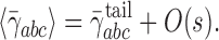 |
19.56 |
The averaged gravitational field is regular in the limit s → 0, in which the tetrad  coincides with
  . Reconstructing the field at x from its frame components gives
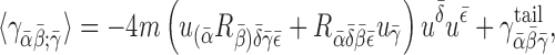 |
19.57 |
where the tail term can be copied from Eq. (19.34),
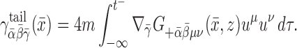 |
19.58 |
The tensors that appear in Eq. (19.57) all refer to the simultaneous point  , which can now be treated as an arbitrary point on the world line γ.
Singular and regular fields
The singular gravitational potentials
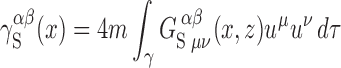 |
19.59 |
are solutions to the wave equation of Eq. (19.22); the singular Green’s function was introduced in Section 16.5. We will see that the singular field  reproduces the singular behaviour of the retarded solution near the world line, and that the difference,
 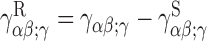 , is smooth on the world line.
To evaluate the integral of Eq. (19.59) we take x to be close to the world line (see Figure 9), and we invoke Eq. (16.31) as well as the Hadamard construction of Eq. (16.37). This gives
 |
19.60 |
where primed indices refer to the retarded point x′ := z(u), double-primed indices refer to the advanced point x″:= z(v), and where  is the advanced distance between x and the world line.
Differentiation of Eq. (19.60) yields
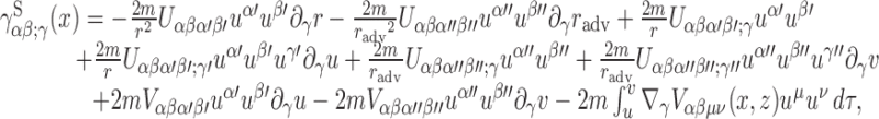 |
19.61 |
and we would like to express this as an expansion in powers of r. For this we will rely on results already established in Section 19.3, as well as additional expansions that will involve the advanced point x″. We recall that a relation between retarded and advanced times was worked out in Eq. (11.12), that an expression for the advanced distance was displayed in Eq. (11.13), and that Eqs. (11.14) and (11.15) give expansions for ∂γv and ∂γradv, respectively; these results can be simplified by setting aa = ȧ0 = ȧa = 0, which is appropriate in this computation.
To derive an expansion for 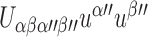 we follow the general method of Section 11.4 and introduce the functions Uαβ(τ) := Uαβμν(x, z)uμuν. We have that
 |
where overdots indicate differentiation with respect to τ and Δ′ := v − u. The leading term  was worked out in Eq. (19.35), and the derivatives of Uαβ(τ) are given by
 |
and
 |
according to Eqs. (19.37) and (16.15). Combining these results together with Eq. (11.12) for Δ′ gives
 |
19.62 |
which should be compared with Eq. (19.35). It should be emphasized that in Eq. (19.62) and all equations below, all frame components are evaluated at the retarded point x′, and not at the advanced point. The preceding computation gives us also an expansion for
 |
which becomes
 |
19.63 |
and which is identical to Eq. (19.37).
We proceed similarly to obtain an expansion for  . Here we introduce the functions Uαβγ(τ) := Uαβμν;γuμuν and express
  as
as  . The leading term
  was computed in Eq. (19.36), and
 |
follows from Eq. (16.14). Combining these results together with Eq. (11.12) for Δ′ gives
 |
19.64 |
and this should be compared with Eq. (19.36). The last expansion we shall need is
 |
19.65 |
which is identical to Eq. (19.38).
We obtain the frame components of the singular gravitational field by substituting these expansions into Eq. (19.61) and projecting against the tetrad  . After some algebra we arrive at
 |
19.66 |
 |
19.67 |
 |
19.68 |
 |
19.69 |
 |
19.70 |
 |
19.71 |
in which all frame components are evaluated at the retarded point x′. Comparison of these expressions with Eqs. (19.39)–(19.44) reveals identical singularity structures for the retarded and singular gravitational fields.
The difference between the retarded field of Eqs. (19.39)–(19.44) and the singular field of Eqs. (19.66)–(19.71) defines the regular gravitational field  . Its frame components are
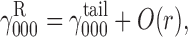 |
19.72 |
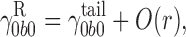 |
19.73 |
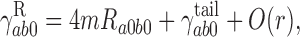 |
19.74 |
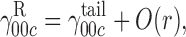 |
19.75 |
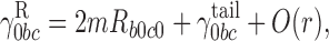 |
19.76 |
 |
19.77 |
and we see that  is regular in the limit r → 0. We may therefore evaluate the regular field directly at x = x′, where the tetrad
  coincides with
  . After reconstructing the field at x′ from its frame components, we obtain
 |
19.78 |
where the tail term can be copied from Eq. (19.34),
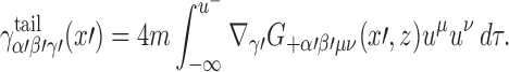 |
19.79 |
The tensors that appear in Eq. (19.79) all refer to the retarded point x′ := z(u), which can now be treated as an arbitrary point on the world line γ.
Equations of motion
The retarded gravitational field γαβ;γ of a point particle is singular on the world line, and this behaviour makes it difficult to understand how the field is supposed to act on the particle and influence its motion. The field’s singularity structure was analyzed in Sections 19.3 and 19.4, and in Section 19.5 it was shown to originate from the singular field  ; the regular field
  was then shown to be regular on the world line.
To make sense of the retarded field’s action on the particle we can follow the discussions of Section 17.6 and 18.6 and postulate that the self gravitational field of the point particle is either 〈γμν;λ〉, as worked out in Eq. (19.57), or  , as worked out in Eq. (19.78). These regularized fields are both given by
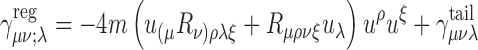 |
19.80 |
and
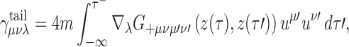 |
19.81 |
in which all tensors are now evaluated at an arbitrary point z(τ) on the world line γ.
The actual gravitational perturbation hαβ is obtained by inverting Eq. (19.10), which leads to  . Substituting Eq. (19.80) yields
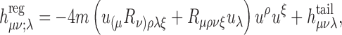 |
19.82 |
where the tail term is given by the trace-reversed counterpart to Eq. (19.81):
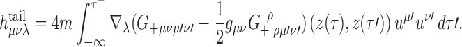 |
19.83 |
When this regularized field is substituted into Eq. (19.13), we find that the terms that depend on the Riemann tensor cancel out, and we are left with
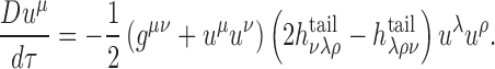 |
19.84 |
We see that only the tail term is involved in the final form of the equations of motion. The tail integral of Eq. (19.83) involves the current position z(τ) of the particle, at which all tensors with unprimed indices are evaluated, as well as all prior positions z(τ′), at which all tensors with primed indices are evaluated. The tail integral is cut short at τ′ = τ− := τ − 0+ to avoid the singular behaviour of the retarded Green’s function at coincidence; this limiting procedure was justified at the beginning of Section 19.3.
Eq. (19.84) was first derived by Yasushi Mino, Misao Sasaki, and Takahiro Tanaka in 1997 [130]. (An incomplete treatment had been given previously by Morette-DeWitt and Ging [133].) An alternative derivation was then produced, also in 1997, by Theodore C. Quinn and Robert M. Wald [150]. These equations are now known as the MiSaTaQuWa equations of motion, and other derivations [83, 144], based on an extended-body approach, will be reviewed below in Part V. It should be noted that Eq. (19.84) is formally equivalent to the statement that the point particle moves on a geodesic in a spacetime with metric  , where
  is the regular metric perturbation obtained by trace-reversal of the potentials
 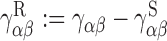 ; this perturbed metric is regular on the world line, and it is a solution to the vacuum field equations. This elegant interpretation of the MiSaTaQuWa equations was proposed in 2003 by Steven Detweiler and Bernard F. Whiting [53]. Quinn and Wald [151] have shown that under some conditions, the total work done by the gravitational self-force is equal to the energy radiated (in gravitational waves) by the particle.
Part V: Motion of a Small Body
Point-particle limits and matched asymptotic expansions
The expansion presented in the previous section is based on an exact point-particle source. But in the full, nonlinear theory, no distributional solution would exist for such a source [80]. Although the expansion nevertheless yields a well-behaved linear approximation, it is ill-behaved beyond that order, since the second- and higher-order Einstein tensors will contain products of delta functions, which have no meaning as distributions. It may be possible to overcome this limitation using more advanced methods such as Colombeau algebras [164], which allow for the multiplication of distributions, but little work has been done to that end. Instead, the common approach, and the one we shall pursue here, has been to abandon the fiction of a point particle in favor of considering an asymptotically small body. As we shall see, we can readily generalize the self-consistent expansion scheme to this case. Furthermore, we shall find that the results of the previous section are justified by this approach: at linear order, the metric perturbation due to an asymptotically small body is precisely that of a point particle moving on a world line with an acceleration given by the MiSaTaQuWa equation (plus higher-order corrections).
In order for the body to be considered “small”, its mass and size must be much smaller than all external lengthscales. We denote these external scales collectively as ℛ, which we may define to be the radius of curvature of the spacetime (were the small body removed from it) in the region in which we seek an approximation. Given this definition, a typical component of the spacetime’s Riemann tensor is equal to 1/ℛ2 up to a numerical factor of order unity. Now, we consider a family of metrics gαβ(ε) containing a body whose mass scales as ε in the limit ε → 0; that is, ε ∼ m/ℛ. If each member of the family is to contain a body of the same type, then the size of the body must also approach zero with ε. The precise scaling of size with ε is determined by the type of body, but it is not generally relevant. What is relevant is the “gravitational size” — the length scale determining the metric outside the body — and this size always scales linearly with the mass. If the body is compact, as is a neutron star or a black hole, then its gravitational size is also its actual linear size. In what remains, we assume that all lengths have been scaled by ℛ, such that we can write, for example, m ≪ 1. Our goal is to determine the metric perturbation and the equation of motion produced by the body in this limit.
Point-particle limits such as this have been used to derive equations of motion many times in the past, including in derivations of geodesic motion at leading order [100, 79, 64] and in constructing post-Newtonian limits [74]. Perhaps the most obvious means of approaching the problem is to first work nonperturbatively, with a body of arbitrary size, and then take the limit. Using this approach (though with some restrictions on the body’s size and compactness) and generalized definitions of momenta, Harte has calculated the self-force in the case of scalar [89] and electromagnetic [90] charge distributions in fixed backgrounds, following the earlier work of Dixon [57, 58, 59]. However, while this approach is conceptually compelling, at this stage it applies only to material bodies, not black holes, and has not yet been presented as part of a systematic expansion of the Einstein equation. Here, we focus instead on a more general method.
Alternatively, one could take the opposite approach, essentially taking the limit first and then trying to recover the higher-order effects, by treating the body as an effective point particle at leading order, with finite size effects introduced as higher-order effective fields, as done by Galley and Hu [76, 75]. However, while this approach is computationally efficient, allowing one to perform high-order calculations with (relative) ease, it requires methods such as dimensional regularization and mass renormalization in order to arrive at meaningful results. Because of these undesirable requirements, we will not consider it here.
In the approach we review, we make use of the method of matched asymptotic expansions [46, 47, 102, 103, 174, 130, 129, 2, 142, 49, 74, 170, 83, 82, 144, 145]. Broadly speaking, this method consists of constructing two different asymptotic expansions, each valid in a specific region, and combining them to form a global expansion. In the present context, the method begins with two types of point-particle limits: an outer limit, in which ε → 0 at fixed coordinate values (we will slightly modify this in a moment); and an inner limit, in which ε → 0 at fixed values of  , where R is a measure of radial distance from the body. In the outer limit, the body shrinks toward zero size as all other distances remain roughly constant; in the inner limit, the small body keeps a constant size while all other distances blow up toward infinity. Thus, the inner limit serves to “zoom in” on a small region around the body. The outer limit can be expected to be valid in regions where R ∼ 1, while the inner limit can be expected to be valid in regions where
  (or R ∼ ε), though both of these regions can be extended into larger domains.
More precisely, consider an exact solution gαβ on a manifold  with two coordinate systems: a local coordinate system Xα = (T, R, ΘA) that is centered (in some approximate sense) on the small body, and a global coordinate system xα. For example, in an extreme-mass-ratio inspiral, the local coordinates might be the Schwarzschild-type coordinates of the small body, and the global coordinates might be the Boyer-Lindquist coordinates of the supermassive Kerr black hole. In the outer limit, we expand gαβ for small ε while holding xα fixed. The leading-order solution in this case is the background metric gαβ on a manifold
  ; this is the external spacetime, which contains no small body. It might, for example, be the spacetime of the supermassive black hole. In the inner limit, we expand gαβ for small ε while holding
  fixed. The leading-order solution in this case is the metric
  on a manifold
  ; this is the spacetime of the small body if it were isolated (though it may include slow evolution due to its interaction with the external spacetime — this will be discussed below). Note that
  and
and  generically differ: in an extreme-mass-ratio inspiral, for example, if the small body is a black hole, then
  will contain a spacelike singularity in the black hole’s interior, while
  will be smooth at the “position” where the small black hole would be. What we are interested in is that “position” — the world line in the smooth external spacetime
  that represents the motion of the small body. Note that this world line generically appears only in the external spacetime, rather than as a curve in the exact spacetime
  ; in fact, if the small body is a black hole, then obviously no such curve exists.
Determining this world line presents a fundamental problem. In the outer limit, the body vanishes at ε = 0, leaving only a remnant, ε-independent curve in  . (Outside any small body, the metric will contain terms such as m/R, such that in the limit m → 0, the limit exists everywhere except at R = 0, which leaves a removable discontinuity in the external spacetime; the removal of this discontinuity defines the remnant world line of the small body.) But the true motion of the body will generically be ε-dependent. If we begin with the remnant world line and correct it with the effects of the self-force, for example, then the corrections must be small: they are small deviation vectors defined on the remnant world line. Put another way, if we expand gαβ in powers of ε, then all functions in it must similarly be expanded, including any representation of the motion, and in particular, any representative world line. We would then have a representation of the form
 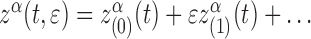 where
where  is a vector defined on the remnant curve described by
  . The remnant curve would be a geodesic, and the small corrections would incorporate the self-force and finite-size effects [83] (see also [102]). However, because the body will generically drift away from any such geodesic, the small corrections will generically grow large with time, leading to the failure of the regular expansion. So we will modify this approach by performing a self-consistent expansion in the outer limit, following the same scheme as presented in the point-particle case. Refs. [144, 145, 143] contain far more detailed discussions of these points.
Regardless of whether the self-consistent expansion is used, the success of matched asymptotic expansions relies on the buffer region defined by ε ≪ R ≪ 1 (see Figure 10). In this region, both the inner and outer expansions are valid. From the perspective of the outer expansion, this corresponds to an asymptotically small region around the world line: R ≪ 1. From the perspective of the inner expansion, it corresponds to asymptotic spatial infinity:  . Because both expansions are valid in this region, and because both are expansions of the same exact metric gαβ and hence must “match,” by working in the buffer region we can use information from the inner expansion to determine information about the outer expansion (or vice versa). We shall begin by solving the Einstein equation in the buffer region, using information from the inner expansion to determine the form of the external metric perturbation therein. In so doing, we shall determine the acceleration of the small body’s world line. Finally, using the field values in the buffer region, we shall construct a global solution for the metric perturbation.
Figure 10.

A small body, represented by the black disk, is immersed in a background spacetime. The internal zone is defined by R ≪ 1, while the external zone is defined by R ≫ ε. Since ε ≪ 1, there exists a buffer region defined by ε ≪ R ≪ 1. In the buffer region ε/R. and R are both small.
In this calculation, the structure of the body is left unspecified. Our only condition is that part of the buffer region must lie outside the body, because we wish to solve the Einstein field equations in vacuum. This requires the body to be sufficiently compact. For example, our calculation would fail for a diffuse body such as our Sun; likewise, it would fail if a body became tidally disrupted. Although we will detail only the case of an uncharged body, the same techniques would apply to charged bodies; Gralla et al. [82] have recently performed a similar calculation for the electromagnetic self-force on an asymptotically small body in a flat background spacetime. Using very different methods, Futamase et al. [73] have calculated equations of motion for an asymptotically small charged black hole.
The structure of our discussion is as follows: In Section 21, we present the self-consistent expansion of the Einstein equation. Next, in Section 22, we solve the equations in the buffer region up to second order in the outer expansion. Last, in Section 23, we discuss the global solution in the outer expansion and show that it is that of a point particle at first order. Over the course of this calculation, we will take the opportunity to incorporate several details that we could have accounted for in the point-particle case but opted to neglect for simplicity: an explicit expansion of the acceleration vector that makes the self-consistent expansion properly systematic, and a finite time domain that accounts for the fact that large errors eventually accumulate if the approximation is truncated at any finite order. For more formal discussions of matched asymptotic expansions in general relativity, see Refs. [104, 145]; the latter reference, in particular, discusses the method as it pertains to the motion of small bodies. For background on the use of matched asymptotic expansions in applied mathematics, see Refs. [63, 96, 109, 111, 178]; the text by Eckhaus [63] provides the most rigorous treatment.
Self-consistent expansion
Introduction
We wish to represent the motion of the body through the external background spacetime  , rather than through the exact spacetime
  . In order to achieve this, we begin by surrounding the body with a (hollow, three-dimensional) world tube Γ embedded in the buffer region. We define the tube to be a surface of constant radius
  in Fermi normal coordinates centered on a world line
  , though the exact definition of the tube is immaterial. Since there exists a diffeomorphism between
  and
and  in the buffer region, this defines a tube
  . Now, the problem is the following: what equation of motion must γ satisfy in order for ΓI to be “centered” about the body?
How shall we determine if the body lies at the centre of the tube’s interior? Since the tube is close to the small body (relative to all external length scales), the metric on the tube is primarily determined by the small body’s structure. Recall that the buffer region corresponds to an asymptotically large spatial distance in the inner expansion. Hence, on the tube, we can construct a multipole expansion of the body’s field, with the form ∑R−n (or ∑s−n — we will assume s ∼ R in the buffer region). Although alternative definitions could be used, we define the tube to be centered about the body if the mass dipole moment vanishes in this expansion. Note that this is the typical approach in general relativity: Whereas in Newtonian mechanics one directly finds the equation of motion for the centre of mass of a body, in general relativity one typically seeks a world line about which the mass dipole of the body vanishes (or an equation of motion for the mass dipole relative to a given nearby world line) [66, 152, 83, 144]. This definition of the world line is sufficiently general to apply to a black hole. If the body is material, one could instead imagine a centre-of-mass world line that lies in the interior of the body in the exact spacetime. This world line would then be the basis of our self-consistent expansion. We use our more general definition to cover both cases. See Ref. [173] and references therein for discussion of multipole expansions in general relativity, see Refs. [173, 174] for discussions of mass-centered coordinates in the buffer region, and see, e.g., Refs. [160, 65] for alternative definitions of centre of mass in general relativity.
As in the point-particle case, in order to determine the equation of motion of the world line, we consider a family of metrics, now denoted gE(x, ε; γ), parametrized by γ, such that when γ is given by the correct equation of motion for a given value of ε, we have gE(x, ε; γ(ε)) = g(x). The metric in the outer limit is, thus, taken to be the general expansion
 |
21.1 |
where
 |
21.2 |
In the point-particle case, solving Einstein’s equations determined the equation of motion of the particle’s world line; in this case, it will determine the world line γ for which the inner expansion is mass-centered. In this self-consistent expansion, the perturbations produced by the body are constructed about a fixed world line determined by the particular value of ε at which one seeks an approximation.
In the remainder of this section, we present a sequence of perturbation equations that arise in this expansion scheme, along with a complementary sequence for the inner expansion.
Field equations in outer expansion
In the outer expansion, we seek a solution in a vacuum region Ω outside of Γ. We specify  to be an open set consisting of the future domain of dependence of the spacelike initial-data surface Σ, excluding the interior of the world tube Γ. This implies that the future boundary of Ω is a null surface
  . Refer to Figure 11 for an illustration. The boundary of the domain is
  . The spatial surface Σ is chosen to intersect Γ at the initial time t = 0.
Figure 11.

The spacetime region Ω is bounded by the union of the spacelike surface Σ, the timelike tube Γ, and the null surface  .
.
Historically, in derivations of the self-force, solutions to the perturbative field equations were taken to be global in time, with tail integrals extended to negative infinity, as we wrote them in the preceding sections. But as was first noted in Ref. [144], because the self-force drives long-term, cumulative changes, any approximation truncated at a given order will be accurate to that order only for a finite time; and this necessites working in a finite region such as Ω. This is also true in the case of point charges and masses. For simplicity, we neglected this detail in the preceding sections, but for completeness, we account for it here.
Field equations
Within this region, we follow the methods presented in the case of a point mass. We begin by reformulating the Einstein equation such that it can be solved for an arbitrary world line. To accomplish this, we assume that the Lorenz gauge can be imposed on the whole of hαβ, everywhere in Ω, such that Lμ[h] = 0. Here
 |
21.3 |
is the Lorenz-gauge operator that was first introduced in Sections 16.1 and 19.1; the condition Lμ[h] = 0 is the same statement as ∇νγμν = 0, where γμν := hμv − ½gμvgαβhαβ is the “trace-reversed” metric perturbation. We discuss the validity of this assumption below.
Just as in the case of a point mass, this choice of gauge reduces the vacuum Einstein equation Rμν = 0 to a weakly nonlinear wave equation that can be expanded and solved at fixed γ. However, we now seek a solution only in the region Ω, where the energy-momentum tensor vanishes, so the resulting sequence of wave equations reads
 |
21.4 |
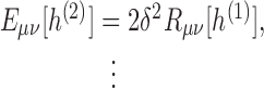 |
21.5 |
where
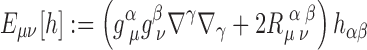 |
21.6 |
is the tensorial wave operator that was first introduced in Sections 16.1 and 19.1, and the second-order Ricci tensor δ2Rμν, which is quadratic in its argument, is shown explicitly in Eq (A.1). More generally, we can write the nth-order equation as
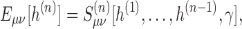 |
21.7 |
where the source term  consists of nonlinear terms in the expansion of the Ricci tensor.
Again as in the case of a point particle, we can easily write down formal solutions to the wave equations, for arbitrary γ. Using the same methods as were used to derive the Kirchoff representation in Section 16.3, we find
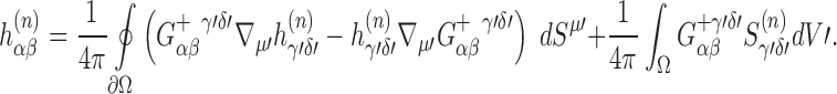 |
21.8 |
Because  is a future null surface, the integral over it vanishes. Hence, this formal solution requires only initial data on Σ and boundary data on Γ. Since Γ lies in the buffer region, the boundary data on it is determined by information from the inner expansion.
One should note several important properties of these integral representations: First, x must lie in the interior of Ω; an alternative expression must be derived if x lies on the boundary [153]. Second, the integral over the boundary is, in each case, a homogeneous solution to the wave equation, while the integral over the volume is an inhomogeneous solution. Third, if the field at the boundary satisfies the Lorenz gauge condition, then by virtue of the wave equation, it satisfies the gauge condition everywhere; hence, imposing the gauge condition to some order in the buffer region ensures that it is imposed to the same order everywhere.
While the integral representation is satisfied by any solution to the associated wave equation, it does not provide a solution. That is, one cannot prescribe arbitrary boundary values on Γ and then arrive at a solution. The reason is that the tube is a timelike boundary, which means that field data on it can propagate forward in time and interfere with the data at a later time. However, by applying the wave operator Eαβ onto Eq. (21.8), we see that the integral representation of  is guaranteed to satisfy the wave equation at each point x ∈ Ω. In other words, the problem arises not in satisfying the wave equation in a pointwise sense, but in simultaneously satisfying the boundary conditions. But since the tube is chosen to lie in the buffer region, these boundary conditions can be supplied by the buffer-region expansion. And as we will discuss in Section 23, because of the asymptotic smallness of the tube, the pieces of the buffer-region expansion diverging as s−n are sufficient boundary data to fully determine the global solution.
Finally, just as in the point-particle case, in order to split the gauge condition into a set of exactly solvable equations, we assume that the acceleration of γ possesses an expansion
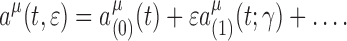 |
21.9 |
This leads to the set of equations
 |
21.10 |
 |
21.11 |
or, more generally, for n > 0,
 |
21.12 |
In these expressions,  is the Lorenz-gauge operator acting on the tensor field fαβ evaluated with
  consists of the terms in Lμ[f] that are linear in
  , and
, and  contains the terms linear in a(n)μ, the combinations a(n − 1)μa(1)ν, and so on. Imposing these gauge conditions on the solutions to the wave equations will determine the acceleration of the world line. Although we introduce an expansion of the acceleration vector in order to obtain a systematic sequence of equations that can be solved exactly, such an expansion also trivially eliminates the need for order-reduction of the resulting equations of motion, since it automatically leads to equations for a(1)μ in terms of a(0)μ, a(2)μ in terms of a(0)μ and a(1)μ, and so on.
Gauge transformations and the Lorenz condition
The outer expansion is defined not only by holding xα fixed, but also by demanding that the mass dipole of the body vanishes when calculated in coordinates centered on γ. If we perform a gauge transformation generated by a vector ξ(1)α(x; γ), then the mass dipole will no longer vanish in those coordinates. Hence, a new world line γ′ must be constructed, such that the mass dipole vanishes when calculated in coordinates centered on that new world line. In other words, in the outer expansion we have the usual gauge freedom of regular perturbation theory, so long as the world line is appropriately transformed as well: (hαβ, γ) → (h′αβ, γ′). The transformation law for the world line was first derived by Barack and Ori [17]; it was displayed in Eq. (1.49), and it will be worked out again in Section 22.6.
Using this gauge freedom, we now justify, to some extent, the assumption that the Lorenz gauge condition can be imposed on the entirety of hαβ. If we begin with the metric in an arbitrary gauge, then the gauge vectors  , etc., induce the transformation
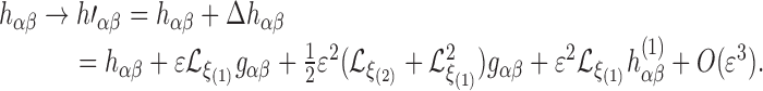 |
21.13 |
if h′αβ is to satisfy the gauge condition Lμ [h′], then ξ must satisfy Lμ [Δh] = −Lμ[h]. After a trivial calculation, this equation becomes
 |
21.14 |
Solving this equation for arbitrary γ, we equate coefficients of powers of ε, leading to a sequence of wave equations of the form
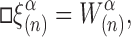 |
21.15 |
where  is a functional of
  and
and  . We seek a solution in the region Ω described in the preceding section. The formal solution reads
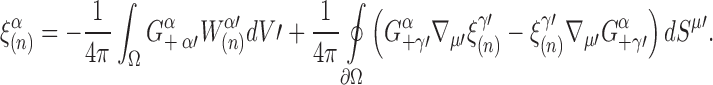 |
21.16 |
From this we see that the Lorenz gauge condition can be adopted to any desired order of accuracy, given the existence of self-consistent data on a tube Γ of asymptotically small radius. We leave the question of the data’s existence to future work. This argument was first presented in Ref. [145].
Field equations in inner expansion
For the inner expansion, we assume the existence of some local polar coordinates Xα = (T, R, ΘA), such that the metric can be expanded for ε → 0 while holding fixed  , and T; to relate the inner and outer expansions, we assume R ∼ s, but otherwise leave the inner expansion completely general.
This leads to the ansatz
 |
21.17 |
where Hαβ at fixed values of  is a perturbation beginning at order ε. This equation represents an asymptotic expansion along flow lines of constant R/ε as ε → 0. It is tensorial in the usual sense of perturbation theory: the decomposition into
  and Hαβ is valid in any coordinates that can be decomposed into ε-independent functions of the scaled coordinates plus O(ε) functions of them. As written, with
  depending only on the scaled coordinates and independent of ε, the indices in Eq. (21.17) can be taken to refer to the unscaled coordinates (T, R, ΘA). However, writing the components in the scaled coordinates will not alter the form of the expansion, but only introduce an overall rescaling of spatial components due to the spatial forms transforming as, e.g.,
  . For example, if the body is a small Schwarzschild black hole of ADM mass εm(T), then in scaled Schwarzschild coordinates
  is given by
 |
21.18 |
As we would expect from the fact that the inner limit follows the body down as it shrinks, all points are mapped to the curve R = 0 at ε = 0, such that the metric in the scaled coordinates naturally becomes one-dimensional at ε = 0. This singular limit can be made regular by rescaling time as well, such that  , and then rescaling the entire metric by a conformal factor 1/ε2. In order to arrive at a global-in-time inner expansion, rather than a different expansion at each time T0, we forgo this extra step. We do, however, make an equivalent assumption, which is that the metric
  and its perturbations are quasistatic (evolving only on timescales ∼ 1). Both approaches are equivalent to assuming that the exact metric contains no high-frequency oscillations occurring on the body’s natural timescale ∼ ε. In other words, the body is assumed to be in equilibrium. If we did not make this assumption, high-frequency oscillations could propagate throughout the external spacetime, invalidating our external expansion.
Since we are interested in the inner expansion only insofar as it informs the outer expansion, we shall not seek to explicitly solve the perturbative Einstein equation in the inner expansion. See Ref. [144] for the forms of the equations and an example of an explicit solution in the case of a perturbed black hole.
General expansion in the buffer region
We now seek the general solution to the equations of the outer expansion in the buffer region. To perform the expansion, we adopt Fermi coordinates centered about γ and expand for small s. In solving the first-order equations, we will determine a(0)μ; in solving the second-order equations, we will determine a(1)μ, including the self-force on the body. Although we perform this calculation in the Lorenz gauge, the choice of gauge is not essential for our purposes here — the essential aspect is our assumed expansion of the acceleration of the world line γ.
Metric expansions
The method of matched asymptotic expansions relies on the fact that the inner and outer expansion agree term by term when re-expanded in the buffer region, where ε ≪ s ≪ 1. To illustrate this idea of matching, consider the forms of the two expansions in the buffer region. The inner expansion holds  constant (since R ∼ s) while expanding for small ε. But if
  is replaced with its value s/ε, the inner expansion takes the form
  , where each term has a dependence on ε that can be expanded in the limit ε → 0 to arrive at the schematic forms gbody(s/ε) = 1⊕ε/s⊕ε2/s2⊕… and εH(1)(s/ε) = s⊕ε⊕ε2/s⊕ ⋯, where ⊕ signifies “plus terms of the form” and the expanded quantities can be taken to be components in Fermi coordinates. Here we have preemptively restricted the form of the expansions, since terms such as s2/ε must vanish because they would have no corresponding terms in the outer expansion. Putting these two expansions together, we arrive at
 |
22.1 |
Since this expansion relies on both an expansion at fixed  and an expansion at fixed s, it can be expected to be accurate if s ≪ 1 and ε ≪ s — that is, in the buffer region ε ≪ s ≪ 1.
On the other hand, the outer expansion holds s constant (since s is formally of the order of the global external coordinates) while expanding for small ε, leading to the form  . But very near the world line, each term in this expansion can be expanded for small s, leading to g = l⊕s⊕s2⊕⋯ and εh(1) = ε/s⊕ε⊕εs⊕ ⋯. (Again, we have restricted this form because terms such as ε/s2 cannot arise in the inner expansion.) Putting these two expansions together, we arrive at
 |
22.2 |
Since this expansion relies on both an expansion at fixed s and an expansion for small s, it can be expected to be accurate in the buffer region ε ≪ s ≪ 1. As we can see, the two buffer-region expansions have an identical form; and because they are expansions of the same exact metric g, they must agree term by term.
One can make use of this fact by first determining the inner and outer expansions as fully as possible, then fixing any unknown functions in them by matching them term by term in the buffer region; this was the route taken in, e.g., Refs. [130, 142, 49, 170]. However, such an approach is complicated by the subtleties of matching in a diffeomorphism-invariant theory, where the inner and outer expansions are generically in different coordinate systems. See Ref. [145] for an analysis of the limitations of this approach as it has typically been implemented. Alternatively, one can take the opposite approach, working in the buffer region first, constraining the forms of the two expansions by making use of their matching, then using the buffer-region information to construct a global solution; this was the route taken in, e.g., Refs. [102, 83, 144]. In general, some mixture of these two approaches can be taken. Our calculation follows Ref. [144]. The only information we take from the inner expansion is its general form, which is characterized by the multipole moments of the body. From this information, we determine the external expansion, and thence the equation of motion of the world line.
Over the course of our calculation, we will find that the external metric perturbation in the buffer region is expressed as the sum of two solutions: one that formally diverges at s = 0 and is entirely determined from a combination of (i) the multipole moments of the internal background metric  , (ii) the Riemann tensor of the external background gαβ, and (iii) the acceleration of the world line γ; and a second solution that is formally regular at s = 0 and depends on the past history of the body and the initial conditions of the field. At leading order, these two solutions are identified as the Detweiler-Whiting singular and regular fields
  and
and  , respectively, and the self-force is determined entirely by
  . Along with the self-force, the acceleration of the world line includes the Papapetrou spin force [138]. This calculation leaves us with the self-force in terms of the the metric perturbation in the neighbourhood of the body. In Section 23, we use the local information from the buffer region to construct a global solution for the metric perturbation, completing the solution of the problem.
The form of the expansion
Before proceeding, we define some notation. We use the multi-index notation  . Angular brackets denote the STF combination of the enclosed indices, and a tensor bearing a hat is an STF tensor. To accommodate this, we now write the Fermi spatial coordinates as xa, instead of
  as they were written in previous sections. Finally, we define the one-forms tα := ∂αt and
  .
.
One should note that the coordinate transformation xα(t, xa) between Fermi coordinates and the global coordinates is ε-dependent, since Fermi coordinates are tethered to an ε-dependent world line. If one were using a regular expansion, then this coordinate transformation would devolve into a background coordinate transformation to a Fermi coordinate system centered on a geodesic world line, combined with a gauge transformation to account for the ε-dependence. But in the self-consistent expansion, the transformation is purely a background transformation, because the ε-dependence in it is reducible to that of the fixed world line.
Because the dependence on ε in the coordinate transformation cannot be reduced to a gauge transformation, in Fermi coordinates the components gαβ of the background metric become ε-dependent. This dependence takes the explicit form of factors of the acceleration aμ(t, ε) and its derivatives, for which we have assumed the expansion ai(t, ε) = a(0)i(t) + a(1)i(t; γ) + O(ε2). There is also an implicit dependence on ε in that the proper time t on the world line depends on ε if written as a function of the global coordinates; but this dependence can be ignored so long as we work consistently with Fermi coordinates.
Of course, even in these ε-dependent coordinates, gμν remains the background metric of the outer expansion, and  is an exact solution to the wave equation (21.7). At first order we will, therefore, obtain
  exactly in Fermi coordinates, for arbitrary aμ. However, for some purposes an approximate solution of the wave equation may suffice, in which case we may utilize the expansion of aμ. Substituting that expansion into gμν and
  yields the buffer-region expansions
 |
22.3 |
 |
22.4 |
where indices refer to Fermi coordinates,  is linear in a(1)i and its derivatives, and for future compactness of notation we define
  , where the subscript ‘B’ stands for ‘buffer’. In the case that a(0)i = 0, these expansions will significantly reduce the complexity of calculations in the buffer region. For that reason, we shall use them in solving the second-order wave equation, but we stress that they are simply a means of economizing calculations in Fermi coordinates; they do not play a fundamental role in the formalism, and one could readily do without them.
Now, we merely assume that in the buffer region there exists a smooth coordinate transformation between the local coordinates (T, R, ΘA) and the Fermi coordinates (t, xa) such that T ∼ t, R ∼ s, and ΘA ∼ θA. The buffer region corresponds to asymptotic infinity s ≫ ε (or  ) in the internal spacetime. So after re-expressing
  as s/ε, the internal background metric can be expanded as
 |
22.5 |
As mentioned above, since the outer expansion has no negative powers of ε, we exclude them from the inner expansion. Furthermore, since  , we must have
  , since these are the only terms independent of both ε and s. Thus, noting that gαβ(xa = 0) = ηαβ := diag(−1, 1, 1, 1), we can write
 |
22.6 |
implying that the internal background spacetime is asymptotically flat.
We assume that the perturbation Hαβ can be similarly expanded in powers of ε at fixed  ,
,
 |
22.7 |
and that each coefficient can be expanded in powers of  to yield
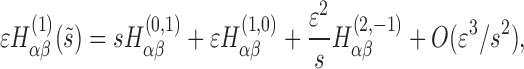 |
22.8 |
 |
22.9 |
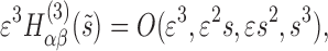 |
22.10 |
where  , the coefficient of εn and sm, is a function of t and θA (and potentially a functional of γ). Again, the form of this expansion is constrained by the fact that no negative powers of ε can appear in the buffer region. (One might think that terms with negative powers of ε could be allowed in the expansion of
  if they are exactly canceled by terms in the expansion of Hαβ, but the differing powers of s in the two expansions makes this impossible.) Note that explicit powers of s appear because
  . Also note that we allow for a logarithmic term at second order in ε; this term arises because the retarded time in the internal background includes a logarithmic correction of the form ε ln s (e.g., t − r → t − r* in Schwarzschild coordinates). Since we seek solutions to a wave equation, this correction to the characteristic curves induces a corresponding correction to the first-order perturbations.
The expansion of Hαβ may or may not hold the acceleration fixed. Regardless of this choice, the general form of the expansion remains valid: incorporating the expansion of the acceleration would merely shuffle terms from one coefficient to another. And since the internal metric  must equal the external metric gαβ + hαβ, the general form of the above expansions of
  and Hαβ completely determines the general form of the external perturbations:
 |
22.11 |
 |
22.12 |
where each  depends only on t and θA, along with an implicit functional dependence on γ. If the internal expansion is performed with aμ held fixed, then the internal and external quantities are related order by order: e.g.,
  , and
, and  . Since we are not concerned with determining the internal perturbations, the only such relationship of interest is
 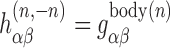 . This equality tells us that the most divergent, s−n piece of the nth-order perturbation
  is defined entirely by the nth-order piece of the internal background metric
  , which is the metric of the body if it were isolated.
To obtain a general solution to the Einstein equation, we write each  as an expansion in terms of irreducible symmetric trace-free pieces:
 |
22.13 |
 |
22.14 |
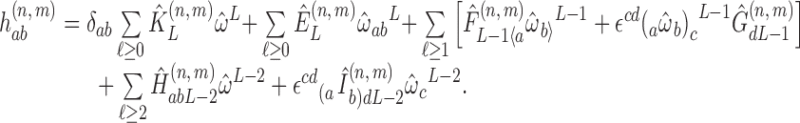 |
22.15 |
Here a hat indicates that a tensor is STF with respect to δab, angular brackets 〈〉 indicate the STF combination of enclosed indices, parentheses indicate the symmetric combination of enclosed indices, and symbols such as  are functions of time (and potentially functionals of γ) and are STF in all their indices. Each term in this expansion is linearly independent of all the other terms. All the quantities on the right-hand side are flat-space Cartesian tensors; their indices can be raised or lowered with δab. Refer to Appendix B for more details about this expansion.
Now, since the wave equations (21.4) and (21.5) are covariant, they must still hold in the new coordinate system, despite the additional ε-dependence. Thus, both equations could be solved for arbitrary acceleration in the buffer region. However, due to the length of the calculations involved, we will instead solve the equations
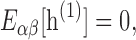 |
22.16 |
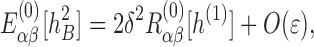 |
22.17 |
where E(0)[f] := E[f]|a=a(0) and δ2R(0)[f] := δ2R[f]|a=a(0). In analogy with the notation used for  and
and  would be linear in
  and
and  would be linear in
  and quadratic in
  , and so on. For a function f ∼ 1,
  , and
, and  correspond to the coefficients of εn in expansions in powers of ε. Equation (22.16) is identical to Eq. (21.4). Equation (22.17) follows directly from substituting Eqs. (22.3) and (22.4) into Eq. (21.5); in the buffer region, it captures the dominant behaviour of
  represented by the approximation
  , but it does not capture its full dependence on acceleration. If one desired a global second-order solution, one might need to solve Eq. (21.5), but for our purpose, which is to determine the first-order acceleration
  , Eq. (22.17) will suffice.
Unlike the wave equations, the gauge conditions (21.10) and (21.11) already incorporate the expansion of the acceleration. As such, they are unmodified by the replacement of the second-order wave equation (21.5) with its approximation (22.17). So we can write
 |
22.18 |
 |
22.19 |
where the first equation is identical to Eq. (21.10), and the second to Eq. (21.11). (The second identity holds because  , since
  differs from
  by
by  , and higher acceleration terms, which are set to zero in
  .) We remind the reader that while this gauge choice is important for finding the external perturbations globally, any other choice would suffice in the buffer region calculation.
In what follows, the reader may safely assume that all calculations are lengthy unless noted otherwise.
First-order solution in the buffer region
In principle, solving the first-order Einstein equation in the buffer region is straightforward. One need simply substitute the expansion of  , given in Eq. (22.11), into the linearized wave equation (22.16) and the gauge condition (22.18). Equating powers of s in the resulting expansions then yields a sequence of equations that can be solved for successively higher-order terms in
  . Solving these equations consists primarily of expressing each quantity in its irreducible STF form, using the decompositions (B.3) and (B.7); since the terms in this STF decomposition are linearly independent, we can solve each equation term by term. This calculation is aided by the fact that
  , so that, for example, the wave operator Eαβ consists of a flat-space Laplacian ∂a∂a plus corrections of order 1/s. Appendix B also lists many useful identities, particularly
  , and the fact that
  is an eigenvector of the flat-space Laplacian:
  .
.
Summary of results
Before proceeding with the calculation, which consists mostly of tedious and lengthy algebra, we summarize the results. The first-order perturbation  consists of two pieces, which we will eventually identify with the Detweiler-Whiting regular and singular fields. In the buffer-region expansion, the regular field consists entirely of unknowns, which is to be expected since as a free radiation field, it must be provided by boundary data. Only when we consider the global solution, in Section 23, will we express it in terms of a tail integral. On the other hand, the singular field is locally determined, and it is characterized by the body’s monopole moment m. More precisely, it is fully determined by the tidal fields of the external background spacetime and the Arnowitt-Deser-Misner mass of the internal background spacetime
  . By itself the wave equation does not restrict the behaviour of this monopole moment, but imposing the gauge condition produces the evolution equations
 |
22.20 |
Hence, at leading order, the body behaves as a test particle, with constant mass and vanishing acceleration.
Order (1,-1)
We now proceed to the details of the calculation. We begin with the most divergent term in the wave equation: the order 1/s3, flat-space Laplacian term
 |
22.21 |
The tt-component of this equation is
 |
22.22 |
from which we read off that Â(1,−1) is arbitrary and  must vanish for all ℓ ≥ 1. The ta-component is
 |
22.23 |
from which we read off that  is arbitrary and all other coefficients must vanish. Lastly, the ab-component is
 |
22.24 |
from which we read off that  and
and  are arbitrary and all other coefficients must vanish. Thus, we find that the wave equation constrains
  to be
to be
 |
22.25 |
This is further constrained by the most divergent, 1/s2 term in the gauge condition, which reads
 |
22.26 |
From the t-component of this equation, we read off  ; from the a-component,
  and
and  . Thus,
  depends only on a single function of time, Â(1,−1). By the definition of the ADM mass, this function (times ε) must be twice the mass of the internal background spacetime. Thus,
  is fully determined to be
 |
22.27 |
where m(t) is defined to be the mass at time t divided by the initial mass ε:= m0. (Because the mass will be found to be a constant, m(t) is merely a placeholder; it is identically unity. We could instead set ε equal to unity at the end of the calculation, in which case m would simply be the mass at time t. Obviously, the difference between the two approaches is immaterial.)
Order (1,0)
At the next order,  , along with the acceleration of the world line and the time-derivative of the mass, first appears in the Einstein equation. The order 1/s2 term in the wave equation is
 |
22.28 |
where the terms on the right arise from the wave operator acting on  . This equation constrains
  to be
to be
 |
22.29 |
Substituting this result into the order 1/s term in the gauge condition, we find
 |
22.30 |
Thus, both the leading-order part of the acceleration and the rate of change of the mass of the body vanish:
 |
22.31 |
Order (1,1)
At the next order,  , along with squares and derivatives of the acceleration, first appears in the Einstein equation, and the tidal fields of the external background couple to
  . The order 1/s term in the wave equation becomes
 |
22.32 |
 |
22.33 |
 |
22.34 |
From the tt-component, we read off that  is arbitrary, Â(1,1) = 4maiai, and
  ; from the ta-component,
  , and
, and  are arbitrary, Ĉi(1,1) = − 2mȧi, and
  , from the ab component,
  , 1),and
  are arbitrary, and
  , and
, and  .
.
Substituting this into the order s0 terms in the gauge condition, we find
 |
22.35 |
where the equation is to be evaluated at  . From the t-component, we read off
 |
22.36 |
From the a-component,
 |
22.37 |
It is understood that both these equations hold only when evaluated at ai = 0.
Thus, the order s component of  is
is
 |
22.38 |
where  and
and  are constrained to satisfy Eqs. (22.36) and (22.37).
First-order solution
To summarize the results of this section, we have  , where
  is given in Eq. (22.27),
  is given in Eq. (22.29), and
  is given in Eq. (22.38). In addition, we have determined that the ADM mass of the internal background spacetime is time-independent, and that the acceleration of the body’s world line vanishes at leading order.
Second-order solution in the buffer region
Though the calculations are much lengthier, solving the second-order Einstein equation in the buffer region is essentially no different from solving the first. We seek to solve the approximate wave equation (22.17), along with the gauge condition (22.19), for the second-order perturbation  ; doing so will also, more importantly, determine the acceleration
  . In this calculation, the acceleration is set to
  everywhere except in the left-hand side of the gauge condition,
  , which is linear in
  .
.
Summary of results
We first summarize the results. As at first order, the metric perturbation contains a regular, free radiation field and a singular, bound field; but in addition to these pieces, it also contains terms sourced by the first-order perturbation. Again, the regular field requires boundary data to be fully determined. And again, the singular field is characterized by the multipole moments of the body: the mass dipole Mi of the internal background metric  , which measures the shift of the body’s centre of mass relative to the world line; the spin dipole Si of
  , which measures the spin of the body about the world line; and an effective correction δm to the body’s mass. The wave equation by itself imposes no restriction on these quantities, but by imposing the gauge condition we find the evolution equations
 |
22.39 |
 |
22.40 |
 |
22.41 |
The first of these tells us that the free radiation field created by the body creates a time-varying shift in the body’s mass. We can immediately integrate it to find
 |
22.42 |
We note that this mass correction is entirely gauge dependent; it could be removed by redefining the time coordinate on the world line. In addition, one could choose to incorporate δm(0) into the leading-order mass m. The second of the equations tells us that the body’s spin is constant at this order; at higher orders, time-dependent corrections to the spin dipole would arise. The last of the equations is the principal result of this section. It tells us that the relationship between the acceleration of the world line and the drift of the body away from it is governed by (i) the local curvature of the background spacetime, as characterized by  — this is the same term that appears in the geodesic deviation equation — (ii) the coupling of the body’s spin to the local curvature — this is the Papapetrou spin force [138] — and (iii) the free radiation field created by the body — this is the self-force. We identify the world line as the body’s by the condition Mi = 0. If we start with initial conditions Mi(0) = 0 = ∂tMi(0), then the mass dipole remains zero for all times if and only if the world line satisfies the equation
 |
22.43 |
This is the equation of motion we sought. It, along with the more general equation containing Mi, will be discussed further in the following section.
Order (2,−2)
We now proceed to the details of the calculation. Substituting the expansion
 |
22.44 |
and the results for  from the previous section into the wave equation and the gauge condition again yields a sequence of equations that can be solved for coefficients of successively higher-order powers (and logarithms) of s. Due to its length, the expansion of the second-order Ricci tensor is given in Appendix A. Note that since the approximate wave equation (22.17) contains an explicit O (ε) correction,
  will be determined only up to O (ε) corrections. For simplicity, we omit these O (ε) symbols from the equations in this section; note, however, that these corrections do not effect the gauge condition, as discussed above.
To begin, the most divergent, order 1/s4 term in the wave equation reads
 |
22.45 |
where the right-hand side is the most divergent part of the second-order Ricci tensor, as given in Eq. (A.3). From the tt-component of this equation, we read off Â(2,−2) = −2m2 and that  is arbitrary. From the ta-component,
  , and
, and  are arbitrary. From the ab-component,
  , and
, and  , and
, and  are arbitrary.
The most divergent, order 1/s3 terms in the gauge condition similarly involve only  ; they read
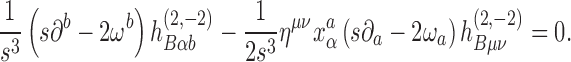 |
22.46 |
After substituting the results from the wave equation, the t-component of this equation determines that  . The a-component determines that
  , and
, and
 |
22.47 |
Thus, the order 1/s2 part of  is given by
 |
22.48 |
where  is given by Eq. (22.47).
The metric perturbation in this form depends on five free functions of time. However, from calculations in flat spacetime, we know that order ε2/s2 terms in the metric perturbation can be written in terms of two free functions: a mass dipole and a spin dipole. We transform the perturbation into this “canonical” form by performing a gauge transformation (cf. Ref. [45]). The transformation is generated by  , the effect of which is to remove
  and.
and. from the metric. This transformation is a refinement of the Lorenz gauge. (Effects at higher order in ε and s will be automatically incorporated into the higher-order perturbations.) The condition
  then becomes
  . The remaining two functions are related to the ADM momenta of the internal spacetime:
 |
22.49 |
where Mi is such that ∂tMi is proportional to the ADM linear momentum of the internal spacetime, and Si is the ADM angular momentum. Mi is a mass dipole term; it is what would result from a transformation xa → xa + Ma/m applied to the 1/s term in  . Si is a spin dipole term. Thus, the order 1/s2 part of
  reads
reads
 |
22.50 |
Order (2,−1)
At the next order, 1/s3, because the acceleration is set to zero,  does not contribute to
  , and
, and  does not contribute to
  . The wave equation hence reads
 |
22.51 |
where  is given in Eqs. (A.4)–(A.6). The tt-component of this equation implies
  , from which we read off that Â(2,−1) is arbitrary and
  . The ta-component implies
  , from which we read off
  and that
  is arbitrary. The ab-component implies
 |
22.52 |
from which we read off that  is arbitrary,
  and
and  is arbitrary. This restricts
  to the form
 |
22.53 |
We next substitute  and
and  into the order 1/s2 terms in the gauge condition. The t-component becomes
 |
22.54 |
from which we read off
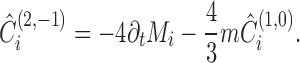 |
22.55 |
And the a-component becomes
 |
22.56 |
from which we read off
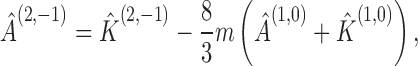 |
22.57 |
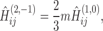 |
22.58 |
and that the angular momentum of the internal background is constant at leading order:
 |
22.59 |
Thus, the order 1/s term in  is given by
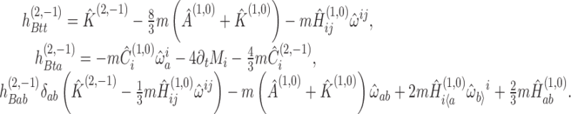 |
22.60 |
Note that the undetermined function  appears in precisely the form of a mass monopole. The value of this function will never be determined (though its time-dependence will be). This ambiguity arises because the mass m that we have defined is the mass of the internal background spacetime, which is based on the inner limit that holds ε/R fixed. A term of the form ε2/R appears as a perturbation of this background, even when, as in this case, it is part of the mass monopole of the body. This is equivalent to the ambiguity in any expansion in one’s choice of small parameter: one could expand in powers of ε, or one could expand in powers of ε + ε2, and so on. It is also equivalent to the ambiguity in defining the mass of a non-isolated body; whether the “mass” of the body is taken to be m or
  is a matter of taste. As we shall discover, the time-dependent part of
  is constructed from the tail terms in the first-order metric perturbation. Hence, the ambiguity in the definition of the mass is, at least in part, equivalent to whether or not one chooses to include the free gravitational field induced by the body in what one calls its mass. (In fact, any order ε incoming radiation, not just that originally produced by the body, will contribute to this effective mass.) In any case, we will define the “correction” to the mass as
Order (2,0,ln)
We next move to the order ln(s)/s2 terms in the wave equation, and the order ln(s)/s terms in the gauge condition, which read
 |
22.61 |
 |
22.62 |
From this we determine
 |
22.63 |
Finally, we arrive at the order 1/s2 terms in the wave equation. At this order, the body’s tidal moments become coupled to those of the external background. The equation reads
 |
22.64 |
where Ẽαβ comprises the contributions from  and
and  , given in Eqs. (A.10), (A.15), and (A.21). The contribution from the second-order Ricci tensor is given in Eqs. (A.7)–(A.9).
Foregoing the details, after some algebra we can read off the solution
 |
22.65 |
 |
22.66 |
 |
22.67 |
where each one of the STF tensors is listed in Table 1.
Table 1.
Symmetric trace-free tensors appearing in the order ε2s0 part of the metric perturbation in the buffer region around the body. Each tensor is a function of the proper time t on the world line γ, and each is STF with respect to the Euclidean metric δij.
|

|
|
|
|
|

|

|
|
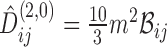
|
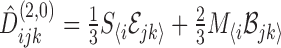
|
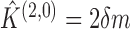
|

|
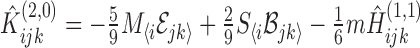
|

|
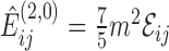
|

|

|
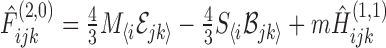
|
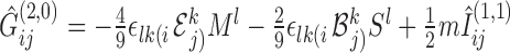
|

|
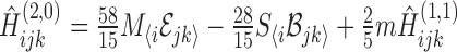
|

|
In solving Eq. (22.64), we also find that the logarithmic term in the expansion becomes uniquely determined:
 |
22.68 |
This term arises because the sources in the wave equation (22.64) contain a term  , which cannot be equated to any term in
  . Thus, the wave equation cannot be satisfied without including a logarithmic term.
Gauge condition
We now move to the final equation in the buffer region: the order 1/s gauge condition. This condition will determine the acceleration  . At this order,
  first contributes to Eq. (22.19):
 |
22.69 |
The contribution from  is most easily calculated by making use of Eqs. (B.24) and (B.25). After some algebra, we find that the t-component of the gauge condition reduces to
 |
22.70 |
and the a-component reduces to
 |
22.71 |
After removing common factors, these equations become Eqs. (22.39) and (22.41). We remind the reader that these equations are valid only when evaluated at  , except in the term
  that arose from
  .
.
Second-order solution
We have now completed our calculation in the buffer region. In summary, the second-order perturbation in the buffer region is given by  ), where
  is given in Eq. (22.50),
  in Eq. (22.60),
  in Eq. (22.65), and
  in Eq. (22.68). In addition, we have found evolution equations for an effective correction to the body’s mass, given by Eq. (22.39), and mass and spin dipoles, given by Eqs. (22.59) and (22.71).
The equation of motion
Master equation of motion
Eq. (22.71) is the principal result of our calculation. After simplification, it reads
 |
22.72 |
We recall that Ma is the body’s mass dipole moment,  and
and  are components of the Riemann tensor of the background spacetime evaluated on the world line,
  is the first-order acceleration of the world line, Sa is the body’s spin angular momentum, and
 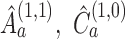 are vector fields on the world line that have yet to be determined. The equation is formulated in Fermi normal coordinates.
Eq. (22.72) is a type of master equation of motion, describing the position of the body relative to a world line of unspecified (though small) acceleration, in terms of the metric perturbation on the world line, the tidal fields of the spacetime it lies in, and the spin of the body. It contains two types of accelerations:  and
and  . The first type is the second time derivative of the body’s mass dipole moment (or the first derivative of its ADM linear momentum), as measured in a frame centered on the world line γ. The second type is the covariant acceleration of the world line through the external spacetime. In other words,
  measures the acceleration of the body’s centre of mass relative to the centre of the coordinate system, while measures the acceleration of the coordinate system itself. As discussed in Section 21, our aim is to identify the world line as that of the body, and we do so via the condition that the mass dipole vanishes for all times, meaning that the body is centered on the world line for all times. If we start with initial conditions Mi (0) = 0 = ∂tMi (0), then the mass dipole remains zero for all times if and only if the world line satisfies the equation
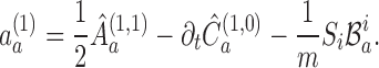 |
22.73 |
This equation of motion contains two types of terms: a Papapetrou spin force, given by  , which arises due to the coupling of the body’s spin to the local magnetic-type tidal field of the external spacetime; and a self-force, arising from homogenous terms in the wave equation. Note that the right-hand side of this equation is to be evaluated at aμ =a(0)μ = 0, and that it would contain an antidamping term
  [92, 93, 150] if we had not assumed that the acceleration possesses an expansion of the form given in Eq. (21.9).
In our self-consistent approach, we began with the aim of identifying γ by the condition that the body must be centered about it for all time. However, we could have begun with a regular expansion, in which the world line is taken to be the remnant γ(0) of the body in the outer limit of ε → 0 with only xμ fixed. In that case the acceleration of the world line would necessarily be ε-independent, so  would be the full acceleration of γ(0). Hence, when we found
  , we would have identified the world line as a geodesic, and there would be no corrections
  for n > 0. We would then have arrived at the equation of motion
 |
22.74 |
This equation of motion was first derived by Gralla and Wald [83] (although they phrased their expansion in terms of an explicit expansion of the world line, with a deviation vector on γ(0), rather than the mass dipole, measuring the correction to the motion). It describes the drift of the body away from the reference geodesic γ(0). This drift is driven partially by the local curvature of the background, as seen in the geodesic-deviation term  , and by the coupling between the body’s spin and the local curvature. It is also driven by the self-force, as seen in the terms containing
  and
and  , but unlike in the self-consistent equation, the fields that produce the self-force are generated by a geodesic past history (plus free propagation from initial data) rather than by the corrected motion.
Although perfectly valid, such an equation is of limited use. If the external background is curved, then Mi has meaning only if the body is “close” to the world line. Thus,  is a meaningful acceleration only for a short time, since Mi will generically grow large as the body drifts away from the reference world line. On that short timescale of validity, the deviation vector defined by Mi accurately points from γ(0) to a “corrected” world line γ; that world line, the approximate equation of motion of which is given in Eq. (22.73), accurately tracks the motion of the body. After a short time, when the mass dipole grows large and the regular expansion scheme begins to break down, the deviation vector will no longer correctly point to the corrected world line. Errors will also accumulate in the field itself, because it is being sourced by the geodesic, rather than corrected, motion.
The self-consistent equation of motion appears to be more robust, and offers a much wider range of validity. Furthermore, even beyond the above step, where we had the option to choose to set either Mi or  to zero, the self-consistent expansion continues to contain within it the regular expansion. Starting from the solution in the self-consistent expansion, one can recover the regular expansion, and its equation of motion (22.74), simply by assuming an expansion for the world line and following the usual steps of deriving the geodesic deviation equation.
Detweiler-Whiting decomposition
Regardless of which equation of motion we opt to use, we have now completed the derivation of the gravitational self-force, in the sense that, given the metric perturbation in the neighbourhood of the body, the self-force is uniquely determined by irreducible pieces of that perturbation. Explicitly, the terms that appear in the self-force are given by
 |
22.75 |
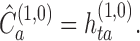 |
22.76 |
This is all that is needed to incorporate the motion of the body into a dynamical system that can be numerically evolved; at each timestep, one simply needs to calculate the field near the world line and decompose it into irreducible pieces in order to determine the acceleration of the body. The remaining difficulty is to actually determine the field at each timestep. In the next section, we will use the formal integral representation of the solution to determine the metric perturbation at the location of the body in terms of a tail integral.
However, before doing so, we emphasize some important features of the self-force and the field near the body. First, note that the first-order external field  splits into two distinct pieces. There is the singular piece
  , given by
 |
22.77 |
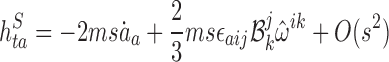 |
22.78 |
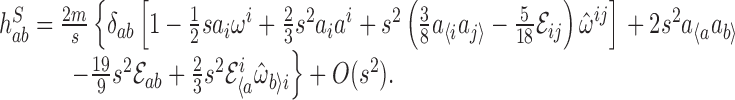 |
22.79 |
This field is a solution to the homogenous wave equation for s > 0, but it is divergent at s = 0. It is the generalization of the 1/s Newtonian field of the body, as perturbed by the tidal fields of the external spacetime gαβ Comparing with results to be derived below in Section 23.2, we find that it is precisely the Detweiler-Whiting singular field for a point mass.
Next, there is the Detweiler-Whiting regular field  , given by
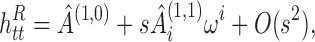 |
22.80 |
 |
22.81 |
 |
22.82 |
This field is a solution to the homogeneous wave equation even at s = 0. It is a free radiation field in the neighbourhood of the body. And it contains all the free functions in the buffer-region expansion.
Now, the acceleration of the body is given by
 |
22.83 |
which we can rewrite as
 |
22.84 |
where  . In other words, up to order ε2 errors, a body with order ε or smaller spin (i.e., one for which Sγδ = 0), moves on a geodesic of a spacetime
  , where
  is a free radiation field in the neighbourhood of the body; a local observer would measure the “background spacetime,” in which the body is in free fall, to have the metric
  instead of gαβ. If we performed a transformation into Fermi coordinates in
  , the metric would contain no acceleration term, and it would take the simple form of a smooth background plus a singular perturbation. Hence, the Detweiler-Whiting axiom is a consequence, rather than an assumption, of our derivation, and we have recovered precisely the picture it provides in the point particle case. In the electromagnetic and scalar cases, Harte has shown that this result is quite general: even for a finite extended body, the field it produces can be split into a homogeneous field [89, 90, 91] that exerts a direct force on the body, and a nonhomogeneous field that exerts only an indirect force by altering the body’s multipole moments. His results should be generalizable to the gravitational case as well.
The effect of a gauge transformation on the force
We now turn to the question of how the world line transforms under a gauge transformation. We begin with the equation of motion (22.41), presented again here:
 |
22.85 |
Setting Mi = 0, we derive the first-order acceleration of γ, given in Eq. (22.73). If, for simplicity, we neglect the Papapetrou spin term, then that acceleration is given by
 |
22.86 |
where it is understood that explicit appearances of the acceleration are to be set to zero on the right-hand side. The first equality follows directly from Eq. (22.73) and the definitions of  and
and  . The second equality follows from the STF decomposition of
  and the integral identities (B.26)–(B.28). We could also readily derive the form of the force given by the Quinn-Wald method of regularization:
  . However, in order to derive a gauge-invariant equation of motion, we shall use the form in Eq. (22.86).
Suppose that we had not chosen a world line for which the mass dipole vanishes, but instead had chosen some “nearby” world line. Then Eq. (22.85) provides the relationship between the acceleration of that world line, the mass dipole relative to it, and the first-order metric perturbations (we again neglect spin for simplicity). The mass dipole is given by  , which has the covariant form
 |
22.87 |
where a primed index corresponds to a point on the world line. Note that the parallel propagator does not interfere with the angle-averaging, because in Fermi coordinates,  . One can also rewrite the first-order-metric-perturbation terms in Eq. (22.85) using the form given in Eq. (22.86). We then have Eq. (22.85) in the covariant form
 |
22.88 |
Now consider a gauge transformation generated by 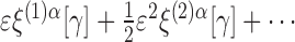 , where is bounded as s → 0, and ξ(2)α diverges as 1/s. More specifically, we assume the expansions ξ(1)α = ξ(1,0)α(t,, θA) + O (s) and
  . (The dependence on γ appears in the form of dependence on proper time t. Other dependences could appear, but it would not affect the result.) This transformation preserves the presumed form of the outer expansion, both in powers of ε and in powers of s. The metric perturbations transform as
 |
22.89 |
 |
22.90 |
Using the results for  , the effect of this transformation on
  is given by
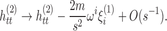 |
22.91 |
The order 1/s2 term arises from  in the gauge transformation. On the right-hand side of Eq. (22.88), the metric-perturbation terms transform as
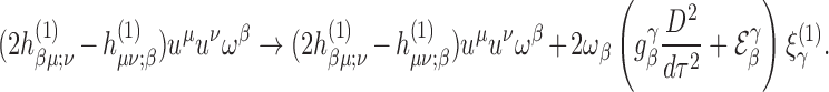 |
22.92 |
The only remaining term in the equation is  . If we extend the acceleration off the world line in any smooth manner, then it defines a vector field that transforms as
  . Since
  , this means that
  — it is invariant under a gauge transformation. It is important to note that this statement applies to the acceleration on the original world line; it does not imply that the acceleration of the body itself is gauge-invariant.
From these results, we find that the left- and right-hand sides of Eq. (22.88) transform in the same way:
 |
22.93 |
Therefore, Eq. (22.88) provides a gauge-invariant relationship between the acceleration of a chosen fixed world line, the mass dipole of the body relative to that world line, and the first-order metric perturbations. So suppose that we begin in the Lorenz gauge, and we choose the fixed world line γ such that the mass dipole vanishes relative to it. Then in some other gauge, the mass dipole will no longer vanish relative to γ, and we must adopt a different, nearby fixed world line γ′. If the mass dipole is to vanish relative to γ′ then the acceleration of that new world line must be given by  , where
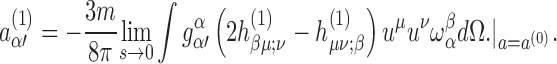 |
22.94 |
Hence, this is a covariant and gauge-invariant form of the first-order acceleration. By that we mean the equation is valid in any gauge, not that the value of the acceleration is the same in every gauge. Under a gauge transformation, a new fixed world line is adopted, and the value of the acceleration on it is related to that on the old world line according to Eq. (22.93). In the particular case that  has no angle-dependence on the world line, this relationship reduces to
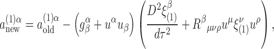 |
22.95 |
as first derived by Barack and Ori [17]. (Here we’ve replaced the tidal field with its expression in terms of the Riemann tensor to more transparently agree with equations in the literature.) An argument of this form was first presented by Gralla [81] for the case of a regular expansion, and was extended to the case of a self-consistent expansion in Ref. [145].
Global solution in the external spacetime
In the previous sections, we have determined the equation of motion of γ in terms of the metric perturbation; we now complete the first-order solution by determining the metric perturbation. In early derivations of the gravitational self-force (excluding those in Refs. [72, 83]), the first-order external perturbation was simply assumed to be that of a point particle. This was first justified by Gralla and Wald [83]. An earlier argument made by D’Eath [46, 47] (and later used by Rosenthal [155]) provided partial justification but was incomplete [144]. Here, we follow the derivation in Ref. [144], which makes use of the same essential elements as D’Eath’s: the integral formulation of the perturbative Einstein equation and the asymptotically small radius of the tube Γ.
Integral representation
Suppose we take our buffer-region expansion of  to be valid everywhere in the interior of Γ (in
  , rather than just in the buffer region. This is a meaningful supposition in a distributional sense, since the 1/s singularity in
  is locally integrable even at γ. Note that the extension of the buffer-region expansion is not intended to provide an accurate or meaningful approximation in the interior; it is used only as a means of determining the field in the exterior. We can do this because the field values in Ω are entirely determined by the field values on γ, so using the buffer-region expansion in the interior of Γ leaves the field values in Ω unaltered. Now, given the extension of the buffer-region expansion, it follows from Stokes’ law that the integral over Γ in Eq. (21.8) can be replaced by a volume integral over the interior of the tube, plus two surface integrals over the “caps”
  and
and  , which fill the “holes” in
  and Σ, respectively, where they intersect Γ. Schematically, we can write Stokes’ law as
 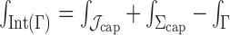 , where Int(Γ) is the interior of Γ. This is now valid as a distributional identity. (Note that the “interior” here means the region bounded by
  ; Int(Γ) does not refer to the set of interior points in the point-set defined by Γ.) The minus sign in front of the integral over Γ accounts for the fact that the directed surface element in Eq. (21.8) points into the tube. Because
  does not lie in the past of any point in Ω, it does not contribute to the perturbation at x ∈ Ω. Hence, we can rewrite Eq. (21.8) as
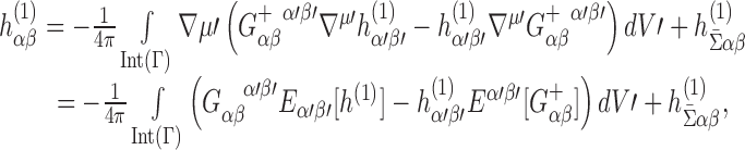 |
23.1 |
where  is the contribution from the spatial surface
  , and
, and  denotes the action of the wave-operator on
  . Now note that
 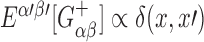 ; since x ∉ Int(Γ), this term integrates to zero. Next note that
  vanishes everywhere except at γ. This means that the field at x can be written as
 |
23.2 |
Making use of the fact that  , along with the identity ∂c∂c (1/s) = −4πδ3(xa), where δ3 is a coordinate delta function in Fermi coordinates, we arrive at the desired result
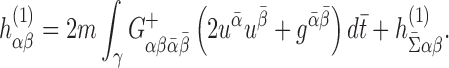 |
23.3 |
Therefore, in the region Ω, the leading-order perturbation produced by the asymptotically small body is identical to the field produced by a point particle. At second order, the same method can be used to simplify Eq. (21.5) by replacing at least part of the integral over Γ with an integral over γ. We will not pursue this simplification here, however.
Gralla and Wald [83] provided an alternative derivation of the same result, using distributional methods to prove that the distributional source for the linearized Einstein equation must be that of a point particle in order for the solution to diverge as 1/s. One can understand this by considering that the most divergent term in the linearized Einstein tensor is a Laplacian acting on the perturbation, and the Laplacian of 1/s is a flat-space delta function; the less divergent corrections are due to the curvature of the background, which distorts the flat-space distribution into a covariant curved-spacetime distribution.
Metric perturbation in Fermi coordinates
Metric perturbation
We have just seen that the solution to the wave equation with a point-mass source is given by
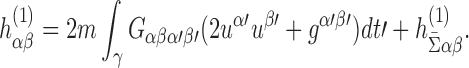 |
23.4 |
One can also obtain this result from Eq. (19.29) by taking the trace-reversal and making use of the Green’s function identity (16.22). In this section, we seek an expansion of the perturbation in Fermi coordinates. Following the same steps as in Section 19.2, we arrive at
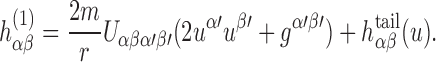 |
23.5 |
Here, primed indices now refer to the retarded point zα (u) on the world line, r is the retarded radial coordinate at x, and the tail integral is given by
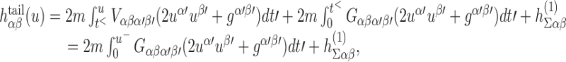 |
23.6 |
where t< is the first time at which the world line enters  , and t = 0 denotes the time when it crosses the initial-data surface Σ.
We expand the direct term in  , in powers of s using the following: the near-coincidence expansion
  ; the relationship between r and s, given by Eq. (11.5); and the coordinate expansion of the parallel-propagators, obtained from the formula
 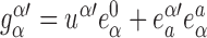 , where the retarded tetrad
  can be expanded in terms of s using Eqs. (11.9), (11.10), (9.12), and (9.13). We expand the tail integral similarly: noting that u = t − s + O (s2), we expand
  about t as
 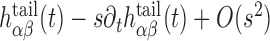 ; each term is then expanded using the near-coincidence expansions
 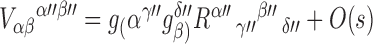 and
and 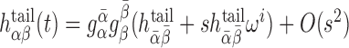 , where barred indices correspond to the point
  , and
, and  . is given by
 |
23.7 |
This yields the expansion
 |
23.8 |
As with the direct part, the final coordinate expansion is found by expressing  in terms of the Fermi tetrad.
Combining the expansions of the direct and tail parts of the perturbation, we arrive at the expansion in Fermi coordinates:
 |
23.9 |
 |
23.10 |
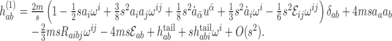 |
23.11 |
As the final step, each of these terms is decomposed into irreducible STF pieces using the formulas (B.1), (B.3), and (B.7), yielding
 |
23.12 |
 |
23.13 |
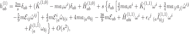 |
23.14 |
where the uppercase hatted tensors are specified in Table 2. Because the STF decomposition is unique, these tensors must be identical to the free functions in Eq. (22.38); hence, those free functions, comprising a regular, homogenous solution in the buffer region, have been uniquely determined by boundary conditions and waves emitted by the particle in the past.
Table 2.
Symmetric trace-free tensors in the first-order metric perturbation in the buffer region, written in terms of the electric-type tidal field  , the acceleration ai, and the tail of the perturbation.

|

|
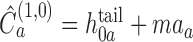
|

|
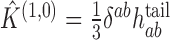
|

|
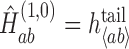
|

|

|

|

|

|
Singular and regular pieces
The Detweiler-Whiting singular field is given by
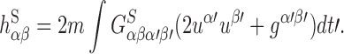 |
23.15 |
Using the Hadamard decomposition  , we can write this as
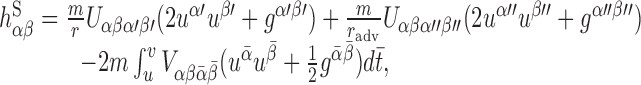 |
23.16 |
where primed indices now refer to the retarded point x′ = z (u); double-primed indices refer to the advanced point x ″ = z (v); barred indices refer to points in the segment of the world line between z (u) and z (v) The first term in Eq. (23.16) can be read off from the calculation of the retarded field. The other terms are expanded using the identities v = u + 2s + O (s2) and 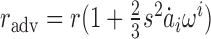 . The final result is
 |
23.17 |
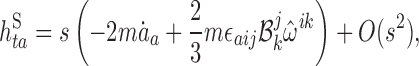 |
23.18 |
 |
23.19 |
The regular field could be calculated from the regular Green’s function. But it is more straight-forwardly calculated using 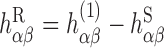 . The result is
 |
23.20 |
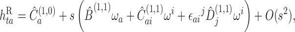 |
23.21 |
 |
23.22 |
Equation of motion
With the metric perturbation fully determined, we can now express the self-force in terms of tail integrals. Reading off the components of  from Table 2 and inserting the results into Eq. (22.84), we arrive at
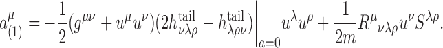 |
23.23 |
We have now firmly established the results of the point-particle analysis.
Concluding remarks
We have presented a number of derivations of the equations that determine the motion of a point scalar charge a point electric charge e, and a point mass m in a specified background spacetime. In this concluding section we summarize these derivations and their foundations. We conclude by describing the next step in the gravitational case: obtaining an approximation scheme sufficiently accurate to extract the parameters of an extreme-mass-ratio inspiral from an observed gravitational waveform.
Our derivations are of two types. The first is based on the notion of an exact point particle. In this approach, we assume that the self-force on the particle arises from a particular piece of its field, either that which survives angle-averaging or the Detweiler-Whiting regular field. The second type is based on the notion of an asymptotically small body, and abandons the fiction of a point particle. In this approach, we don’t assume anything about the body’s equation of motion, but rather derive it directly from the field equations. Although we have presented such a derivation only in the gravitational case, analogous ones could be performed in the scalar and electromagnetic cases, using conservation of energy-momentum instead of the field equations alone. Such a calculation was performed by Gralla et al. [82] in the restricted case of an electric charge in a flat background.
Perhaps the essential result of our derivation based on an asymptotically small body is that it confirms all of the results derived using point particles: at linear order in the body’s mass, the field it creates is identical to that of a point particle, and its equation of motion is precisely that derived from physically motivated axioms for a point particle. In other words, at linear order, not only can we get away with the fiction of a point particle, but our assumptions about the physics governing its motion are also essentially correct.
The motion of a point particle
Spatial averaging
Our first means of deriving equations of motion for point particles is based on spatial averaging. In this approach, we assume the following axiom:
the force on the particle arises from the piece of the field that survives angle averaging.
For convenience in our review, we consider the case of a point electric charge and adopt the Detweiler-Whiting decomposition of the Faraday tensor into singular and regular pieces,  . We average Fαβ over a sphere of constant proper distance from the particle. We then evaluate the averaged field at the particle’s position. Because the regular field is nonsingular on the world line, this yields
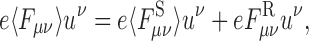 |
where
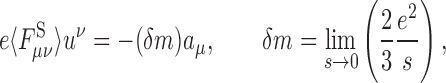 |
and
 |
We now postulate that the equations of motion are maμ = e 〈Fμν 〉uν, where m is the particle’s bare mass. With the preceding results we arrive at 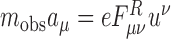 where mobs ≡ rn +δm is the particle’s observed (renormalized) inertial mass.
In this approach, the fiction of a point particle manifests itself in the need for mass renormalization. Such a requirement can be removed, even within the point-particle picture, by adopting the “comparison axiom” proposed by Quinn and Wald [150]. If we consider extended (but small) bodies, no such renormalization is required, and the equations of motion follow directly from the conservation of energy-momentum. However, the essential assumption about the nature of the force is valid: only the piece of the field that survives angle-averaging exerts a force on the body.
The Detweiler—Whiting Axiom
Our second means of deriving equations of motion for point particles is based on the Detweiler-Whiting axiom, which asserts that
the singular field exerts no force on the particle; the entire self-force arises from the action of the regular field.
This axiom, which is motivated by the symmetric nature of the singular field, and also its causal structure, gives rise to the same equations of motion as the averaging method. In this picture, the particle simply interacts with a free field (whose origin can be traced to the particle’s past), and the procedure of mass renormalization is sidestepped. In the scalar and electromagnetic cases, the picture of a particle interacting with a free radiation field removes any tension between the nongeodesic motion of the charge and the principle of equivalence. In the gravitational case the Detweiler-Whiting axiom produces a generalized equivalence principle (cf. Ref. [74]): up to order ε2 errors, a point mass m moves on a geodesic of the spacetime with metric  , which is nonsingular and a solution to the vacuum field equations. This is a conceptually powerful, and elegant, formulation of the MiSaTaQuWa equations of motion. And it remains valid for (non-spinning) small bodies.
Resolving historical ambiguities
Although they yield the correct physical description, the above axioms are by themselves insufficient, and historically, two problems have arisen in utilizing them: One, they led to ill-behaved equations of motion, requiring a process of order reduction; and two, in the gravitational case they led to equations of motion that are inconsistent with the field equations, requiring the procedure of gauge-relaxation. Both of these problems arose because the expansions were insufficiently systematic, in the sense that they did not yield exactly solvable perturbation equations. In the approach taken in our review, we have shown that these problems do not arise within the context of a systematic expansion. Although we have done so only in the case of an extended body, where we sought a higher degree of rigor, one could do the same in the case of point particles by expanding in the limit of small charge or mass (see, e.g., the treatment of a point mass in Ref. [144]).
Consider the Abraham-Lorentz-Dirac equation 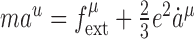 . To be physically meaningful and mathematically well-justified, it must be thought of as an approximate equation of motion for a localized matter distribution with small charge e ≪ 1. But it contains terms of differing orders e0 and e2, and the acceleration itself is obviously a function of e. Hence, the equation has not been fully expanded. One might think that it is somehow an exact equation, despite its ill behaviour. Or one might replace it with the order-reduced equation
  to eliminate that ill behaviour. But one can instead assume that aμ (e), like other functions of e, possesses an expansion in powers of e, leading to the two well-behaved equations
  and
and  . However, the fact that such an equation can even arise indicates that one has not begun with a systematic expansion of the governing field equations (in this case, the conservation equation and the Maxwell equations). If one began with a systematic expansion, with equations exactly solvable at each order, no such ambiguity would arise.
The same can be said of the second problem. It is well known that in general relativity, the motion of gravitating bodies is determined by the Einstein field equations; the equations of motion cannot be separately imposed. And specifically, if we deal with the linearized Einstein equation δGαβ [h(1)] = 8πTαβ [γ ], where Tαβ is the energy-momentum tensor of a point particle in the background spacetime, then the linearized Bianchi identity requires the point particle to move on a geodesic of the background spacetime. This seems to contradict the MiSaTaQuWa equation and therefore the assumptions we made in deriving it. In order to remove this inconsistency, the earliest derivations [130, 150] invoked an a posteriori gauge-relaxation: rather than solving a linearized Einstein equation exactly, they solved the wave equation Eαβ [h(1)] = − 16πTαβ in combination with the relaxed gauge condition Lα [εh(1)] = O (ε2). The allowed errors in the gauge condition carry over into the linearized Bianchi identity, such that it no longer restricts the motion to be geodesic. In this approach, one is almost solving the linearized problem one set out to solve. But again, such an a posteriori corrective measure is required only if one begins without a systematic expansion. The first-order metric perturbation is a functional of a world line; if we allow that world line to depend on ε, then the metric has evidently not been fully expanded in powers of ε. To resolve the problem, one needs to carefully deal with this fact.
In the approach we have adopted here, following Ref. [144], we have resolved these problems via a self-consistent expansion in which the world line is held fixed while expanding the metric. Rather than beginning with the linear field equation, we began by reformulating the exact equation in the form
 |
24.1 |
 |
24.2 |
These equations we systematically expanded by (i) treating the metric perturbation as a functional of a fixed world line, keeping the dependence on the world line fixed while expanding, and (ii) expanding the acceleration of the world line. Since we never sought a solution to the equation δGαβ [h(1)] = 8πTαβ [γ ] [7], no tension arose between the equation of motion and the field equation. In addition, we dealt only with exactly solvable perturbative equations: rather then imposing the ad hoc a posteriori gauge condition Lμ [εh(1)] = O (ε2), our approach systematically led to the conditions  and
and  , which can be solved exactly. Like in the issue of order reduction, the essential step in arriving at exactly solvable equations is assuming an expansion of the particle’s acceleration.
Historically, these issues were first resolved by Gralla and Wald [83] using a different method. Rather than allowing an ε-dependence in the first-order perturbation, they fully expanded every function in the problem in a power series, including the world line itself. In this approach, the world line of the body is found to be a geodesic, but higher-order effects arise in deviation vectors measuring the drift of the particle away from that geodesic. Such a method has the drawback of being limited to short timescales, since the deviation vectors will eventually grow large as the body moves away from the initial reference geodesic.
The motion of a small body
Although the above results for point particles require assumptions about the form of the force, their results have since been derived from first principles, and the physical pictures they are based on have proven to be justified: An asymptotically small body behaves as a point particle moving on a geodesic of the smooth part of the spacetime around it, or equivalently, it moves on a world line accelerated by the asymmetric part of its own field.
In addition to a derivation from first principles, we also seek a useful approximation scheme. Any such scheme must deal with the presence of multiple distinct scales. Most obviously, these are the mass and size of the body itself and the lengthscales of the external universe, but other scales also arise. For example, in order to accurately represent the physics of an extreme-mass-ratio system, we must consider changes over four scales: First, there is the large body’s mass, which is the characteristic lengthscale of the external universe. For convenience, since all lengths are measured relative to this one, we rescale them such that this global lengthscale is ∼ 1. Second, there is the small body’s mass ∼ ε, which is the scale over which the gravitational field changes near the body; since the body is compact, this is also the scale of its linear size. Third, there is the radiation-reaction time ∼ 1/ε; this is the time over which the small effects of the self-force accumulate to produce significant changes, specifically the time required for quantities such as the small body’s energy and angular momentum to accumulate order 1 changes. Fourth, there is the large distance to the wave zone. We will not discuss this last scale here, but dealing with it analytically would likely require matching a wave solution at null infinity to an expansion formally expected to be valid in a region of size ∼ 1/ε.
Self-consistent and matched asymptotic expansions
In this review, we have focused on a self-consistent approximation scheme first presented in Refs. [144, 145, 143]. It deals with the small size of the body using two expansions. Near the body, to capture changes on the short distances ∼ ε, we adopt an inner expansion in which the body remains of constant size while all other distances approach infinity. Outside of this small neibourhood around the body, we adopt an outer expansion in which the body shrinks to zero mass and size about an ε-dependent world line that accurately reflects its long-term motion. The world line γ is defined in the background spacetime of the outer expansion. Its acceleration is found by solving the Einstein equation in a buffer region surrounding the body, where both expansions are valid; in this region, both expansions must agree, and we can use the multipole moments of the inner expansion to determine the outer one. In particular, we define γ to be the body’s world line if and only if the body’s mass dipole moment vanishes when calculated in coordinates centered on it. As in the point-particle calculation, the essential step in arriving at exactly solvable equations and a well-behaved equation of motion is an assumed expansion of the acceleration on the world line.
In order to construct a global solution in the outer expansion, we first recast the Einstein equation in a form that can be expanded and solved for an arbitrary world line. As in the point-particle case, we accomplish this by adopting the Lorenz gauge for the total metric perturbation. We can then write formal solutions to the perturbation equations at each order as integrals over a small tube surrounding the body (plus an initial data surface). By embedding the tube in the buffer region, we can use the data from the buffer-region expansion to determine the global solution. At first order, we find that the metric perturbation is precisely that of a point particle moving on the world line γ. While the choice of gauge is not essential in finding an expression for the force in terms of the field in the buffer-region expansion, it is essential in our method of determining the global field. Without making use of the relaxed Einstein equations, no clear method of globally solving the Einstein equation presents itself, and no simple split between the perturbation and the equation of motion arises.
Because this expansion self-consistently incorporates the corrections to the body’s motion, it promises to be accurate on long timescales. Specifically, when combined with the first-order metric perturbation, the first-order equation of motion defines a solution to the Einstein equation that we expect to be accurate up to order ε2 errors over times t ≲ 1/ε. When combined with the second-order perturbation, it defines a solution we expect to be accurate up to order ε3 errors on the shorter timescale ∼ 1.
This approach closely mirrors the extremely successful methods of post-Newtonian theory [74]. In particular, both schemes recast the Einstein equation in a relaxed form before expanding it. Also, our use of an inner limit near the body is analogous to the “strong-field point particle limit” exploited by Futamase and his collaborators [74]. And our calculation of the equation of motion is somewhat similar to the methods used by Futamase and others [74, 152], in that it utilizes a multipole expansion of the body’s metric in the buffer region.
Alternative methods
Various other approaches have been taken to deal with the multiple scales in the problem. In particular, even the earliest paper on the gravitational self-force [130] made use of inner and outer limits, which were also used in different forms in later derivations [142, 49, 72]. However, those early derivations are problematic. Specifically, they never adequately define the world line for which they derive equations of motion.
In the method of matched asymptotic expansions used in Refs. [130, 142, 49], the first-order perturbation in the outer expansion is assumed to be that of a point particle, with an attendant world line, and the inner expansion is assumed to be that of a perturbed black hole; by matching the two expansions in the buffer region, the acceleration of the world line is determined. Since the forms of the inner and outer expansions are already restricted, this approach’s conclusions have somewhat limited strength, but it has more fundamental problems as well. The matching procedure begins by expanding the outer expansion in powers of distance s (or r) from the world line, and the inner expansion for large spacial distances R ≫ ε. But the two expansions begin in different coordinate systems with an unknown relationship between them. In particular, there is no given relationship between the world line and the “position” of the black hole. The two expansions are matched by finding a coordinate transformation that makes them agree in the buffer region. However, because there is no predetermined relationship between the expansions, this transformation is not in fact unique, and it does not yield a unique equation of motion. One can increase the strength of the matching condition in order to arrive at unique results, but that further weakens the strength of the conclusions. Refer to Ref. [145] for a discussion of these issues.
Rather than finding the equation of motion from the field equations, as in the above calculations, Fukumoto et al. [72] found the equation of motion by defining the body’s linear momentum as an integral over the body’s interior and then taking the derivative of that momentum. But they then required an assumed relationship between the momentum and the four-velocity of a representative world line in the body’s interior. Hence, the problem is again an inadequate definition of the body’s motion. Because it involves integrals over the body’s interior, and takes the world line to lie therein, this approach is also limited to material bodies; it does not apply to black holes.
The first reliable derivation of the first-order equation of motion for an asymptotically small body was performed by Gralla and Wald [83], who used a method of the same nature as the one presented here, deriving equations of motion by solving the field equations in the buffer region. As we have seen, however, their derivation is based on an expansion of the world line in powers of ε instead of a self-consistent treatment that keeps it fixed.
Using very different methods, Harte has also provided reliable derivations of equations of motion for extended bodies interacting with their own scalar and electromagnetic fields in fixed background spacetimes [89, 90, 91]. His approach is based on generalized definitions of momenta, the evolution of which is equivalent to energy-momentum conservation. The momenta are defined in terms of generalized Killing fields the essential property of which is that they satisfy £ξgαβ|γ = ∇γ£ξgαβ|γ = 0 − that is, they satisfy Killing’s equation on the body’s world line and approximately satisfy it “nearby.” Here the world line can be defined in multiple ways using, for example, center-of-mass conditions. This approach is nonperturbative, with no expansion in the limit of small mass and size (though it does require an upper limit on the body’s size and a lower limit on its compactness). It has the advantage of very naturally deriving a generalization of the Detweiler-Whiting axiom: The field of an extended body can be split into (i) a solution to the vacuum field equations which exerts a direct self-force, and (ii) a solution to the equations sourced by the body, which shifts the body’s multipole moments. This approach has not yet been applied to gravity, but such an application should be relatively straightforward. However, as with the approach of Fukumoto et al. [72], this one does not apply to black holes.
Other methods have also been developed (or suggested) to accomplish the same goals as the self-consistent expansion. Most prominent among these is the two-timescale expansion suggested by Hinderer and Flanagan [94]. As discussed in Section 2, their method splits the orbital evolution into slow and fast dynamics by introducing slow and fast time variables. In the terminology of Section 22, this method constructs a general expansion by smoothly transitioning between regular expansions constructed at each value of the slow time variable, with the transition determined by the evolution with respect to the slow time. On the scale of the fast time, the world line is a geodesic; but when the slow time is allowed to vary, the world line transitions between geodesics to form the true, accelerated world line. This results in a global, uniform-in-time approximation. One should note that simply patching together a sequence of regular expansions, by shifting to a new geodesic every so often using the deviation vector, would not accomplish this: Such a procedure would accumulate a secular error in both the metric perturbation and the force, because the perturbation would be sourced by a world line secularly deviating from the position of the body, and the force would be calculated from this erroneous perturbation. The error would be proportional to the number of “shifts” multiplied by a nonlinear factor depending on the time between them. And this error would, formally at least, be of the same magnitude as the solution itself.
The fundamental difference between the self-consistent expansion and the two-timescale expansion is the following: In the two-timescale method, the Einstein equation, coupled to the equation of motion of the small body, is reduced to a dynamical system that can be evolved in time. The true world line of the body then emerges from the evolution of this system. In the method presented here, we have instead sought global, formal solutions to the Einstein equation, written in terms of global integrals; to accomplish this, we have treated the world line of the body as a fixed structure in the external spacetime. However, the two methods should agree. Note, though, that the two-timescale expansion is limited to orbits in Kerr, and it requires evolution equations for the slow evolution of the large black hole’s mass and spin parameters, which have not yet been derived. Since the changes in mass and spin remain small on a radiation-reaction timescale, in the self-consistent expansion presented here they are automatically incorporated into the perturbations  . It is possible that this incorporation leads to errors on long timescales, in which case a different approach, naturally allowing slow changes in the background, would be more advantageous.
Beyond first order
The primary experimental motivation for researching the self-force is to produce waveform templates for LISA. In order to extract the parameters of an extreme-mass-ratio binary from a waveform, we require a waveform that is accurate up to errors of order after a radiation-reaction time ∼ 1/ε. If we use the first-order equation of motion, we will be neglecting an acceleration ∼ ε2, which will lead to secular errors of order unity after a time ∼ 1/ε. Thus, the second-order self-force is required in order to obtain a sufficiently accurate waveform template. In order to achieve the correct waveform, we must also obtain the second-order part of the metric perturbation; this can be easily done, at least formally, using the global integral representations outside a world tube. However, a practical numerical calculation may prove difficult, since one would not wish to excise the small tube from one’s numerical domain, and the second-order perturbation would diverge too rapidly on the world line to be treated straightforwardly.
A formal expression for the second-order force has already been derived by Rosenthal [155, 156]. However, he expresses the second-order force in a very particular gauge in which the first-order self-force vanishes. This is sensible on short timescales, but not on long timescales, since it forces secular changes into the first-order perturbation, presumably leading to the first-order perturbation becoming large with time. Furthermore, it is not a convenient gauge, since it does not provide what we wish it to: a correction to the nonzero leading-order force in the Lorenz gauge.
Thus, we wish to obtain an alternative to Rosenthal’s derivation. Based on the methods reviewed in this article, there is a clear route to deriving the second-order force. One would construct a buffer-region expansion accurate up to order ε3. Since one would require the order ε2s terms in this expansion, in order to determine the acceleration, one would need to increase the order of the expansion in r as well. Specifically, one would need terms up to orders ε0s3, εs2, ε2s, and ε3s0. In such a calculation, one would expect the following terms to appear: the body’s quadrupole moment Qab, corrections ∂Mi and ∂Si to its mass and spin dipoles, and a second-order correction ∂2m to its mass. Although some ambiguity may arise in defining the world line of the body at this order, a reasonable definition appears to be to guarantee that ∂Mi vanishes. However, at this order one may require some model of the body’s internal dynamics, since the equation of motion will involve the body’s quadrupole moment, for which the Einstein equation is not expected to yield an evolution equation. But if one seeks only the second-order self-force, one could simply neglect the quadrupole by assuming that the body is spherically symmetric in isolation. In any case, the force due to the body’s quadrupole moment is already known from various other methods: see, e.g., the work of Dixon [57, 58, 59]; more recent methods can be found in Ref. [165] and references therein.
Because such a calculation could be egregiously lengthy, one may consider simpler methods, perhaps requiring stronger assumptions. For example, one could straightforwardly implement the method of matched asymptotic expansions with the matching conditions discussed in Ref. [145], in which one makes strong assumptions about the relationship between the inner and outer expansions. The effective field theory method used by Galley and Hu [75] offers another possible route.
Alternatively, one could calculate only part of the second-order force. Specifically, as described in Section 2.5, Hinderer and Flanagan [94, 69] have shown that one requires in fact only the averaged dissipative part of the second-order force. This piece of the force can be calculated within an adiabatic approximation, in which the rates of change of orbital parameters are calculated from the radiative Green’s function, asymptotic wave amplitudes, and information about the orbit that sources them. Hence, we might be able to forgo a complete calculation of the second-order force, and use instead the complete first-order force in conjunction with an adiabatic approximation for the second-order force.
The self-force, however, is of interest beyond its relevance to LISA. The full second-order force would be useful for more general purposes, such as more accurate comparisons to post-Newtonian theory, and analysis of other systems, such as intermediate mass ratio binaries. Perhaps most importantly, it is of fundamental importance in our understanding of the motion of small bodies. For these reasons, proceeding to second order in a systematic expansion, and thereby obtaining second-order expressions for the force on a small body, remains an immediate goal.
Acknowledgments
Our understanding of the work presented in this review was shaped by a series of annual meetings named after the movie director Frank Capra. The first of these meetings took place in 1998 and was held at Capra’s ranch in Southern California; the ranch now belongs to Caltech, Capra’s alma mater. Subsequent meetings were held in Dublin (1999), Pasadena (2000), Potsdam (2001), State College PA (2002), Kyoto (2003), Brownsville (2004), Oxford (2005), Milwaukee (2006), Hunstville (2007), Orléans (2008), Bloomington (2009), and Waterloo (2010). At these meetings and elsewhere we have enjoyed many instructive conversations with Paul Anderson, Warren Anderson, Patrick Brady, Claude Barrabès, Leor Barack, Luc Blanchet, Lior Burko, Manuela Campanelli, Marc Casals, Peter Diener, Steve Detweiler, Sam Dolan, Steve Drasco, Scott Field, Éanna Flanagan, John Friedman, Ryuichi Fujita, Chad Galley, Darren Golbourn, Sam Gralla, Roland Haas, Abraham Harte, Wataru Hikida, Tanja Hinderer, Scott Hughes, Werner Israel, Toby Keidl, Dong-hoon Kim, Alexandre Le Tiec, Carlos Lousto, Eirini Messaritaki, Yasushi Mino, Hiroyuki Nakano, Amos Ori, Larry Price, Eran Rosenthal, Norichika Sago, Misao Sasaki, Abhay Shah, Carlos Sopuerta, Alessandro Spallicci, Hideyuki Tagoshi, Takahiro Tanaka, Jonathan Thornburg, Bill Unruh, Bob Wald, Niels Warburton, Barry Wardell, Alan Wiseman, and Bernard Whiting. This work was supported by the Natural Sciences and Engineering Research Council of Canada.
Second-order expansions of the Ricci tensor
We present here various expansions used in solving the second-order Einstein equation in Section 22.4. We require an expansion of the second-order Ricci tensor δ2Rαβ, defined by
 |
A.1 |
where γ is the trace-reversed metric perturbation, and an expansion of a certain piece of Eμν [h(2)] Specifically, we require an expansion of  in powers of the Fermi radial coordinate s, where for a function f
 consists of δ2Rαβ [f ]with the acceleration set to zero. We write
 |
A.2 |
where the second superscript index in parentheses denotes the power of s Making use of the expansion of  obtained by setting the acceleration to zero in the results for
  found in Section 22.3, one finds
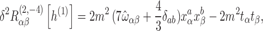 |
A.3 |
and
 |
A.4 |
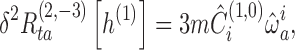 |
A.5 |
 |
A.6 |
and
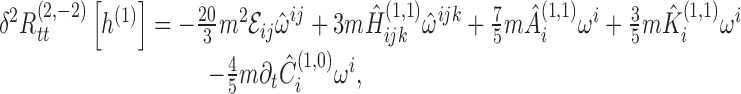 |
A.7 |
 |
A.8 |
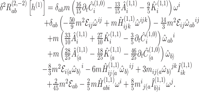 |
A.9 |
Next, we require an analogous expansion of  , where
  is defined for any f by setting the acceleration to zero in Eaβ [f ]. The coefficients of the 1/r4 and 1/r3 terms in this expansion can be found in Section 22.4; the coefficient of 1/r2 will be given here. For compactness, we define this coefficient to be Ẽαβ. The tt-component of this quantity is given by
 |
A.10 |
The ta-component is given by
 |
A.11 |
This can be decomposed into irreducible STF pieces via the identities
 |
A.12 |
 |
A.13 |
 |
A.14 |
which follow from Eqs. (B.3) and (B.7), and which lead to
 |
A.15 |
The ab-component is given by
 |
A.16 |
Again, this can be decomposed, using the identities
 |
A.17 |
 |
A.18 |
 |
A.19 |
 |
A.20 |
which lead to
 |
A.21 |
STF multipole decompositions
All formulas in this appendix are either taken directly from Refs. [27] and [45] or are easily derivable from formulas therein.
Any Cartesian tensor field depending on two angles θA spanning a sphere can be expanded in a unique decomposition in symmetric trace-free tensors. Such a decomposition is equivalent to a decomposition in tensorial harmonics, but it is sometimes more convenient. It begins with the fact that the angular dependence of a Cartesian tensor Ts (θA) can be expanded in a series of the form
 |
B.1 |
where S and L denote multi-indices S = i1…is and L = j1… jℓ, angular brackets denote an STF combination of indices, is a Cartesian unit vector, ωL := ωj1 … ωjℓ, and  . This is entirely equivalent to an expansion in spherical harmonics. Each coefficient Ts〈L 〉 can be foundfrom the formula
 |
B.2 |
where the double factorial is defined by x !! = x (x − 2) ⋯ 1. These coefficients can then be decomposed into irreducible STF tensors. For example, for s = 1, we have
 |
B.3 |
where the  are STF tensors given by
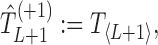 |
B.4 |
 |
B.5 |
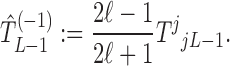 |
B.6 |
Similarly, for a symmetric tensor Ts with s = 2, we have
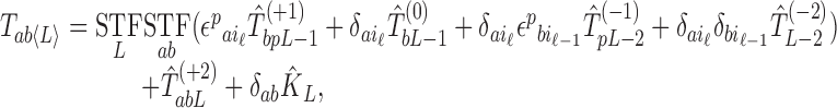 |
B.7 |
where
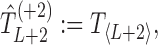 |
B.8 |
 |
B.9 |
 |
B.10 |
 |
B.11 |
 |
B.12 |
 |
B.13 |
These decompositions are equivalent to the formulas for addition of angular momenta, J = S + L, which results in terms with angular momentum ℓ − s ≤ j ≤ ℓ + s; the superscript labels (±n) in these formulas indicate by how much each term’s angular momentum differs from ℓ.
By substituting Eqs. (B.3) and (B.7) into Eq. (B.1), we find that a scalar, a Cartesian 3-vector, and the symmetric part of a rank-2 Cartesian 3-tensor can be decomposed as, respectively,
 |
B.14 |
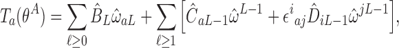 |
B.15 |
 |
B.16 |
Each term in these decompositions is algebraically independent of all the other terms.
We can also reverse a decomposition to “peel off” a fixed index from an STF expression:
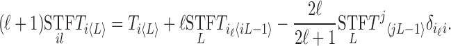 |
B.17 |
In evaluating the action of the wave operator on a decomposed tensor, the following formulas are useful:
 |
B.18 |
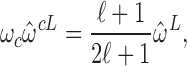 |
B.19 |
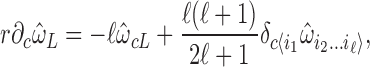 |
B.20 |
 |
B.21 |
 |
B.22 |
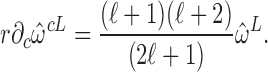 |
B.23 |
In evaluating the t-component of the Lorenz gauge condition, the following formula is useful for finding the most divergent term (in an expansion in r):
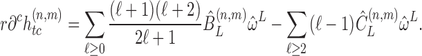 |
B.24 |
And in evaluating the a-component, the following formula is useful for the same purpose:
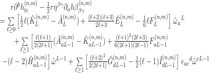 |
B.25 |
where we have defined  and
and  .
.
The unit vector satisfies the following integral identities:
 |
B.26 |
 |
B.27 |
 |
B.28 |
where the curly braces indicate the smallest set of permutations of indices that make the result symmetric. For example,δ{ab}ωc = δabωc + δbcωa + δcaωb.
Contributor Information
Eric Poisson, Email: poisson@uoguelph.ca, http://www.physics.uoguelph.ca/.
Adam Pound, Email: apound@uoguelph.ca.
Ian Vega, Email: ianvega@uoguelph.ca.
References
- [1].Akcay S. Fast frequency-domain algorithm for gravitational self-force: Circular orbits in Schwarzschild spacetime. Phys. Rev. D. 2011;83:124026. doi: 10.1103/PhysRevD.83.124026. [DOI] [Google Scholar]
- [2].Alvi K. Approximate binary-black-hole metric. Phys. Rev. D. 2000;61(124013):1–19. [Google Scholar]
- [3].Anderson PR, Eftekharzadeh A, Hu BL. Self-force on a scalar charge in radial infall from rest using the Hadamard-WKB expansion. Phys. Rev. D. 2006;73:064023. doi: 10.1103/PhysRevD.73.064023. [DOI] [Google Scholar]
- [4].Anderson PR, Hu BL. Radiation reaction in Schwarzschild spacetime: Retarded Green’s function via Hadamard-WKB expansion. Phys. Rev. D. 2004;69:064039. doi: 10.1103/PhysRevD.69.064039. [DOI] [Google Scholar]
- [5].Anderson WG, Flanagan ÉÉ, Ottewill AC. Quasilocal contribution to the gravitational self-force. Phys. Rev. D. 2005;71:024036. doi: 10.1103/PhysRevD.71.024036. [DOI] [Google Scholar]
- [6].Anderson WG, Wiseman AG. A matched expansion approach to practical self-force calculations. Class. Quantum Grav. 2005;22:S783–S800. doi: 10.1088/0264-9381/22/15/010. [DOI] [Google Scholar]
- [7].Barack L. Self-force on a scalar particle in spherically symmetric spacetime via mode-sum regularization: Radial trajectories. Phys. Rev. D. 2000;62(084027):1–21. [Google Scholar]
- [8].Barack L. Gravitational self-force by mode sum regularization. Phys. Rev. D. 2001;64(084021):1–16. [Google Scholar]
- [9].Barack L. Gravitational self-force in extreme mass-ratio inspirals. Class. Quantum Grav. 2009;26:213001. doi: 10.1088/0264-9381/26/21/213001. [DOI] [Google Scholar]
- [10].Barack L, Burko LM. Radiation-reaction force on a particle plunging into a black hole. Phys. Rev. D. 2000;62(084040):1–5. [Google Scholar]
- [11].Barack L, Damour T, Sago N. Precession effect of the gravitational self-force in a Schwarzschild spacetime and the effective one-body formalism. Phys. Rev. D. 2010;82:084036. doi: 10.1103/PhysRevD.82.084036. [DOI] [Google Scholar]
- [12].Barack L, Golbourn DA. Scalar-field perturbations from a particle orbiting a black hole using numerical evolution in 2+1 dimensions. Phys. Rev. D. 2007;76:044020. doi: 10.1103/PhysRevD.76.044020. [DOI] [Google Scholar]
- [13].Barack L, Golbourn DA, Sago N. m-mode regularization scheme for the self-force in Kerr spacetime. Phys. Rev. D. 2007;76:124036. doi: 10.1103/PhysRevD.76.124036. [DOI] [Google Scholar]
- [14].Barack L, Lousto CO. Computing the gravitational self-force on a compact object plunging into a Schwarzschild black hole. Phys. Rev. D. 2002;66(061502):1–5. [Google Scholar]
- [15].Barack L, Mino Y, Nakano H, Ori A, Sasaki M. Calculating the Gravitational Self-Force in Schwarzschild Spacetime. Phys. Rev. Lett. 2002;88(091101):1–4. doi: 10.1103/PhysRevLett.88.091101. [DOI] [PubMed] [Google Scholar]
- [16].Barack L, Ori A. Mode sum regularization approach for the self-force in black hole spacetime. Phys. Rev. D. 2000;61(061502):1–5. [Google Scholar]
- [17].Barack L, Ori A. Gravitational self-force and gauge transformations. Phys. Rev. D. 2001;64(124003):1–13. [Google Scholar]
- [18].Barack L, Ori A. Regularization parameters for the self-force in Schwarzschild space-time: Scalar case. Phys. Rev. D. 2002;66(084022):1–15. [Google Scholar]
- [19].Barack L, Ori A. Gravitational Self-Force on a Particle Orbiting a Kerr Black Hole. Phys. Rev. Lett. 2003;90(111101):1–4. doi: 10.1103/PhysRevLett.90.111101. [DOI] [PubMed] [Google Scholar]
- [20].Barack L, Ori A. Regularization parameters for the self-force in Schwarzschild space-time. II. Gravitational and electromagnetic cases. Phys. Rev. D. 2003;67(024029):1–11. [Google Scholar]
- [21].Barack L, Sago N. Gravitational self-force on a particle in circular orbit around a Schwarzschild black hole. Phys. Rev. D. 2007;75:064021. doi: 10.1103/PhysRevD.75.064021. [DOI] [PubMed] [Google Scholar]
- [22].Barack L, Sago N. Gravitational Self-Force Correction to the Innermost Stable Circular Orbit of a Schwarzschild Black Hole. Phys. Rev. Lett. 2009;102:191101. doi: 10.1103/PhysRevLett.102.191101. [DOI] [PubMed] [Google Scholar]
- [23].Barack L, Sago N. Gravitational self-force on a particle in eccentric orbit around a Schwarzschild black hole. Phys. Rev. D. 2010;81:084021. doi: 10.1103/PhysRevD.81.084021. [DOI] [PubMed] [Google Scholar]
- [24].Barack L, Sago N. Beyond the geodesic approximation: Conservative effects of the gravitational self-force in eccentric orbits around a Schwarzschild black hole. Phys. Rev. D. 2011;83:084023. doi: 10.1103/PhysRevD.83.084023. [DOI] [Google Scholar]
- [25].Barton JL, Lazar D, Kennefick DJ, Khanna G, Burko LM. Computational efficiency of frequency- and time-domain calculations of extreme mass-ratio binaries: Equatorial orbits. Phys. Rev. D. 2010;78:064042. doi: 10.1103/PhysRevD.78.064042. [DOI] [Google Scholar]
- [26].Blanchet, L., “Gravitational Radiation from Post-Newtonian Sources and Inspiralling Compact Binaries”, Living Rev. Relativity, 9, lrr-2006-4, (2006). [arXiv:gr-qc/0202016]. URL (accessed 25 August 2010): http://www.livingreviews.org/lrr-2006-4. (Cited on page 125.) [DOI] [PMC free article] [PubMed]
- [27].Blanchet L, Damour T. Radiative gravitational fields in general relativity I. General structure of the field outside the source. Philos. Trans. R. Soc. London, Ser. A. 1986;320:379–430. doi: 10.1098/rsta.1986.0125. [DOI] [Google Scholar]
- [28].Blanchet L, Detweiler S, Le Tiec A, Whiting BF. High-order post-Newtonian fit of the gravitational self-force for circular orbits in the Schwarzschild geometry. Phys. Rev. D. 2010;81:084033. doi: 10.1103/PhysRevD.81.084033. [DOI] [Google Scholar]
- [29].Blanchet L, Detweiler S, Le Tiec A, Whiting BF. Post-Newtonian and numerical calculations of the gravitational self-force for circular orbits in the Schwarzschild geometry. Phys. Rev. D. 2010;81:064004. doi: 10.1103/PhysRevD.81.064004. [DOI] [Google Scholar]
- [30].Burko LM. Self-Force on a Particle in Orbit around a Black Hole. Phys. Rev. Lett. 2000;84:4529–4532. doi: 10.1103/PhysRevLett.84.4529. [DOI] [PubMed] [Google Scholar]
- [31].Burko LM. Self-force on static charges in Schwarzschild spacetime. Class. Quantum Grav. 2000;17:227–250. doi: 10.1088/0264-9381/17/1/316. [DOI] [Google Scholar]
- [32].Burko LM. The importance of conservative self forces for binaries undergoing radiation damping. Int. J. Mod. Phys. A. 2001;16:1471–1479. doi: 10.1142/S0217751X01003639. [DOI] [Google Scholar]
- [33].Burko LM, Harte AI, Poisson E. Mass loss by a scalar charge in an expanding universe. Phys. Rev. D. 2002;65(124006):1–11. [Google Scholar]
- [34].Burko L, Khanna G. Accurate time-domain gravitational waveforms for extreme-mass-ratio binaries. Europhys. Lett. 2007;78:60005. doi: 10.1209/0295-5075/78/60005. [DOI] [Google Scholar]
- [35].Burko LM, Liu YT. Self-force on a scalar charge in the spacetime of a stationary, axisymmetric black hole. Phys. Rev. D. 2001;64(024006):1–21. [Google Scholar]
- [36].Burko LM, Liu YT, Soen Y. Self-force on charges in the spacetime of spherical shells. Phys. Rev. D. 2001;63(024015):1–18. [Google Scholar]
- [37].Canizares P, Sopuerta CF. Efficient pseudospectral method for the computation of the self-force on a charged particle: Circular geodesics around a Schwarzschild black hole. Phys. Rev. D. 2009;79:084020. doi: 10.1103/PhysRevD.79.084020. [DOI] [Google Scholar]
- [38].Canizares P, Sopuerta CF, Jaramillo JL. Pseudospectral collocation methods for the computation of the self-force on a charged particle: Generic orbits around a Schwarzschild black hole. Phys. Rev. D. 2010;82:044023. doi: 10.1103/PhysRevD.82.044023. [DOI] [Google Scholar]
- [39].Casals M, Dolan S, Ottewill AC, Wardell B. Padé approximants of the Green function in spherically symmetric spacetimes. Phys. Rev. D. 2009;79:124044. doi: 10.1103/PhysRevD.79.124044. [DOI] [Google Scholar]
- [40].Casals M, Dolan S, Ottewill AC, Wardell B. Self-force calculations with matched expansions and quasinormal mode sums. Phys. Rev. D. 2009;79:124043. doi: 10.1103/PhysRevD.79.124043. [DOI] [Google Scholar]
- [41].Chrzanowski PL. Vector potential and metric perturbations of a rotating black hole. Phys. Rev. D. 1975;11:2042–2062. doi: 10.1103/PhysRevD.11.2042. [DOI] [Google Scholar]
- [42].Cohen JM, Kegeles LS. Electromagnetic fields in curved spaces: a constructive procedure. Phys. Rev. D. 1974;10:1070–1084. doi: 10.1103/PhysRevD.10.1070. [DOI] [Google Scholar]
- [43].Copson ET. On Electrostatics in a Gravitational Field. Proc. R. Soc. London, Ser. A. 1928;116:720–735. [Google Scholar]
- [44].Damour T. Gravitational self-force in a Schwarzschild background and the effective one-body formalism. Phys. Rev. D. 2010;81:024017. doi: 10.1103/PhysRevD.81.024017. [DOI] [Google Scholar]
- [45].Damour T, Iyer BR. Multipole analysis for electromagnetism and linearized gravity with irreducible Cartesian tensors. Phys. Rev. D. 1991;43:3259–3272. doi: 10.1103/PhysRevD.43.3259. [DOI] [PubMed] [Google Scholar]
- [46].D’Eath PD. Dynamics of a small black hole in a background universe. Phys. Rev. D. 1975;11:1387–1403. doi: 10.1103/PhysRevD.11.1387. [DOI] [Google Scholar]
- [47].D’Eath PD. Black Holes: Gravitational Interactions. Oxford; New York: Clarendon Press; Oxford University Press; 1996. [Google Scholar]
- [48].Décanini Y, Folacci A. Off-diagonal coefficients of the DeWitt-Schwinger and Hadamard representations of the Feynman propagator. Phys. Rev. D. 2006;73(044027):1–38. [Google Scholar]
- [49].Detweiler S. Perspective on gravitational self-force analyses. Class. Quantum Grav. 2005;22:681–716. doi: 10.1088/0264-9381/22/15/006. [DOI] [Google Scholar]
- [50].Detweiler S. Consequence of the gravitational self-force for circular orbits of the Schwarzschild geometry. Phys. Rev. D. 2008;77:124026. doi: 10.1103/PhysRevD.77.124026. [DOI] [Google Scholar]
- [51].Detweiler S, Messaritaki E, Whiting BF. Self-force of a scalar field for circular orbits about a Schwarzschild black hole. Phys. Rev. D. 2003;67:104016. doi: 10.1103/PhysRevD.67.104016. [DOI] [Google Scholar]
- [52].Detweiler S, Poisson E. Low multipole contributions to the gravitational self-force. Phys. Rev. D. 2004;69:084019. doi: 10.1103/PhysRevD.69.084019. [DOI] [Google Scholar]
- [53].Detweiler S, Whiting BF. Self-force via a Green’s function decomposition. Phys. Rev. D. 2003;67:024025. doi: 10.1103/PhysRevD.67.024025. [DOI] [Google Scholar]
- [54].DeWitt BS, Brehme RW. Radiation Damping in a Gravitational Field. Ann. Phys. (N.Y.) 1960;9:220–259. doi: 10.1016/0003-4916(60)90030-0. [DOI] [Google Scholar]
- [55].Diaz-Rivera LM, Messaritaki E, Whiting BF, Detweiler S. Scalar field self-force effects on orbits about a Schwarzschild black hole, eccentric orbits. Phys. Rev. D. 2004;70:124018. doi: 10.1103/PhysRevD.70.124018. [DOI] [Google Scholar]
- [56].Dirac PAM. Classical theory of radiating electrons. Proc. R. Soc. London, Ser. A. 1938;167:148. doi: 10.1098/rspa.1938.0124. [DOI] [Google Scholar]
- [57].Dixon WG. Dynamics of extended bodies in general relativity. I. Momentum and angular momentum. Proc. R. Soc. London, Ser. A. 1970;314:499–527. doi: 10.1098/rspa.1970.0020. [DOI] [Google Scholar]
- [58].Dixon WG. Dynamics of extended bodies in general relativity. II. Moments of the charge-current vector. Proc. R. Soc. London, Ser. A. 1970;319:509–547. doi: 10.1098/rspa.1970.0191. [DOI] [Google Scholar]
- [59].Dixon WG. Dynamics of Extended Bodies in General Relativity. III. Equations of Motion. Philos. Trans. R. Soc. London, Ser. A. 1974;277:59–119. doi: 10.1098/rsta.1974.0046. [DOI] [Google Scholar]
- [60].Dolan S, Barack L. Self-force via m-mode regularization and 2+1D evolution: Foundations and a scalar-field implementation on Schwarzschild spacetime. Phys. Rev. D. 2011;83:124019. doi: 10.1103/PhysRevD.83.024019. [DOI] [Google Scholar]
- [61].Drasco S, Flanagan ÉÉ, Hughes SA. Computing inspirals in Kerr in the adiabatic regime: I. The scalar case. Class. Quantum Grav. 2005;22:S801–S846. doi: 10.1088/0264-9381/22/15/011. [DOI] [Google Scholar]
- [62].Drasco S, Hughes SA. Gravitational wave snapshots of generic extreme mass ratio inspirals. Phys. Rev. D. 2006;73:024027. doi: 10.1103/PhysRevD.73.024027. [DOI] [Google Scholar]
- [63].Eckhaus W. Asymptotic Analysis of Singular Perturbations. Amsterdam; New York: North-Holland; 1979. [Google Scholar]
- [64].Ehlers J, Geroch R. Equation of motion of small bodies in relativity. Ann. Phys. (N.Y.) 2004;309:232–236. doi: 10.1016/j.aop.2003.08.020. [DOI] [Google Scholar]
- [65].Ehlers J, Rudolph E. Dynamics of extended bodies in general relativity center-of-mass description and quasirigidity. Gen. Relativ. Gravit. 1977;8:197–217. doi: 10.1007/BF00763547. [DOI] [Google Scholar]
- [66].Einstein A, Infeld L. On the motion of particles in general relativity theory. Can. J. Math. 1949;1:209. doi: 10.4153/CJM-1949-020-8. [DOI] [Google Scholar]
- [67].Field SE, Hesthaven JS, Lau SR. Discontinuous Galerkin method for computing gravitational waveforms from extreme mass ratio binaries. Class. Quantum Grav. 2009;26:165010. doi: 10.1088/0264-9381/26/16/165010. [DOI] [Google Scholar]
- [68].Field SE, Hesthaven JS, Lau SR. Persistent junk solutions in time-domain modeling of extreme mass ratio binaries. Phys. Rev. D. 2010;81:124030. doi: 10.1103/PhysRevD.81.124030. [DOI] [Google Scholar]
- [69].Flanagan, É.É. and Hinderer, T., “Transient resonances in the inspirals of point particles into black holes”, arXiv, e-print, (2010). [arXiv:1009.4923 [gr-qc]]. (Cited on pages 38 and 171.) [DOI] [PubMed]
- [70].Flanagan ÉÉ, Wald RM. Does back reaction enforce the averaged null energy condition in semiclassical gravity? Phys. Rev. D. 1996;54:6233–6283. doi: 10.1103/PhysRevD.54.6233. [DOI] [PubMed] [Google Scholar]
- [71].Friedlander FG. The wave equat on on a curved space-time. Cambridge; New York: Cambridge University Press; 1975. [Google Scholar]
- [72].Fukumoto T, Futamase T, Itoh Y. On the equation of motion for a fast moving small object using the strong field point particle limit. Prog. Theor. Phys. 2006;116:423–428. doi: 10.1143/PTP.116.423. [DOI] [Google Scholar]
- [73].Futamase T, Hogan PA, Itoh Y. Equations of Motion in General Relativity of a Small Charged Black Hole. Phys. Rev. D. 2008;78:104014. doi: 10.1103/PhysRevD.78.104014. [DOI] [Google Scholar]
- [74].Futamase, T. and Itoh, Y., “The Post-Newtonian Approximation for Relativistic Compact Binaries”, Living Rev. Relativity, 10, lrr-2007-2, (2007). URL (accessed 25 August 2010): http://www.livingreviews.org/lrr-2007-2. (Cited on pages 135, 136, 166, 168, and 169.) [DOI] [PMC free article] [PubMed]
- [75].Galley CR, Hu BL. Self-force on extreme mass ratio inspirals via curved spacetime effective field theory. Phys. Rev. D. 2009;79:064002. doi: 10.1103/PhysRevD.79.064002. [DOI] [Google Scholar]
- [76].Galley CR, Hu BL, Lin S-Y. Electromagnetic and gravitational self-force on a relativistic particle from quantum fields in curved space. Phys. Rev. D. 2006;74:024017. doi: 10.1103/PhysRevD.74.024017. [DOI] [Google Scholar]
- [77].Gal’tsov DV. Radiation reaction in the Kerr gravitational field. J. Phys. A: Math. Gen. 1982;15:3737–3749. doi: 10.1088/0305-4470/15/12/025. [DOI] [Google Scholar]
- [78].Ganz K, Hikida W, Nakano H, Sago N, Tanaka T. Adiabatic evolution of three ‘constants’ of motion for greatly inclined orbits in Kerr spacetime. Prog. Theor. Phys. 2007;117:1041–1066. doi: 10.1143/PTP.117.1041. [DOI] [Google Scholar]
- [79].Geroch R, Jang PS. Motion of a body in general relativity. J. Math. Phys. 1975;16:65–67. doi: 10.1063/1.522416. [DOI] [Google Scholar]
- [80].Geroch R, Traschen J. Strings and other distributional sources in general relativity. Phys. Rev. D. 1987;36:1017–1031. doi: 10.1103/PhysRevD.36.1017. [DOI] [PubMed] [Google Scholar]
- [81].Gralla, S.E., “Comments on First and Second Order Gravitational Self-Force”, Presentation at the 12th Capra Meeting on Radiation Reaction, conference paper, (2009). (Cited on page 160.)
- [82].Gralla SE, Harte AI, Wald RM. A Rigorous Derivation of Electromagnetic Self-force. Phys. Rev. D. 2009;80:024031. doi: 10.1103/PhysRevD.80.024031. [DOI] [Google Scholar]
- [83].Gralla SE, Wald RM. A Rigorous Derivation of Gravitational Self-force. Class. Quantum Grav. 2008;25:205009. doi: 10.1088/0264-9381/25/20/205009. [DOI] [Google Scholar]
- [84].Haas R. Scalar self-force on eccentric geodesics in Schwarzschild spacetime: a time-domain computation. Phys. Rev. D. 2007;75:124011. doi: 10.1103/PhysRevD.75.124011. [DOI] [Google Scholar]
- [85].Haas R. Self-force on point particles in orbit around a Schwarzschild black hole. Guelph: University of Guelph; 2008. [Google Scholar]
- [86].Haas R, Poisson E. Mass change and motion of a scalar charge in cosmological space-times. Class. Quantum Grav. 2005;22:S739–S752. doi: 10.1088/0264-9381/22/15/008. [DOI] [Google Scholar]
- [87].Haas R, Poisson E. Mode-sum regularization of the scalar self-force: Formulation in terms of a tetrad decomposition of the singular field. Phys. Rev. D. 2006;74:004009. doi: 10.1103/PhysRevD.74.044009. [DOI] [Google Scholar]
- [88].Hadamard J. Lectures on Cauchy’s Problem in Linear Partial Differential Equations. New Haven, CT: Yale University Press; 1923. [Google Scholar]
- [89].Harte AI. Self-forces from generalized Killing fields. Class. Quantum Grav. 2008;25:235020. doi: 10.1088/0264-9381/25/23/235020. [DOI] [Google Scholar]
- [90].Harte AI. Electromagnetic self-forces and generalized Killing fields. Class. Quantum Grav. 2009;26:155015. doi: 10.1088/0264-9381/26/15/155015. [DOI] [Google Scholar]
- [91].Harte AI. Effective stress-energy tensors, self-force, and broken symmetry. Class. Quantum Grav. 2010;27:135002. doi: 10.1088/0264-9381/27/13/135002. [DOI] [Google Scholar]
- [92].Havas P. Radiation Damping in General Relativity. Phys. Rev. 1957;108(5):1351–1352. doi: 10.1103/PhysRev.108.1351. [DOI] [Google Scholar]
- [93].Havas P, Goldberg JN. Lorentz-Invariant Equations of Motion of Point Masses in the General Theory of Relativity. Phys. Rev. 1962;128(1):398–414. doi: 10.1103/PhysRev.128.398. [DOI] [Google Scholar]
- [94].Hinderer T, Flanagan ÉÉ. Two timescale analysis of extreme mass ratio inspirals in Kerr. I. Orbital Motion. Phys. Rev. D. 2008;78:064028. doi: 10.1103/PhysRevD.78.064028. [DOI] [Google Scholar]
- [95].Hobbs JM. A Vierbein Formalism for Radiation Damping. Ann. Phys. (N.Y.) 1968;47:141–165. doi: 10.1016/0003-4916(68)90231-5. [DOI] [Google Scholar]
- [96].Holmes MH. Introduction to Perturbation Methods. Berlin; New York: Springer; 1995. [Google Scholar]
- [97].Huerta EA, Gair JR. Influence of conservative corrections on parameter estimation for EMRIs. Phys. Rev. D. 2009;79:084021. doi: 10.1103/PhysRevD.79.084021. [DOI] [Google Scholar]
- [98].Hughes S. Evolution of circular, nonequatorial orbits of Kerr black holes due to gravitational-wave emission. Phys. Rev. D. 2000;61:084004. doi: 10.1103/PhysRevD.61.084004. [DOI] [Google Scholar]
- [99].Hughes S, Drasco S, Flanagan ÉÉ, Franklin J. Gravitational radiation reaction and inspiral waveforms in the adiabatic limit. Phys. Rev. Lett. 2005;94:221101. doi: 10.1103/PhysRevLett.94.221101. [DOI] [PubMed] [Google Scholar]
- [100].Infeld L, Schild A. On the Motion of Test Particles in General Relativity. Rev. Mod. Phys. 1949;21:408–413. doi: 10.1103/RevModPhys.21.408. [DOI] [Google Scholar]
- [101].Jackson JD. Classical Electrodynamics. 3. New York: Wiley; 1999. [Google Scholar]
- [102].Kates RE. Motion of a small body through an external field in general relativity calculated by matched asymptotic expansions. Phys. Rev. D. 1980;22:1853–1870. doi: 10.1103/PhysRevD.22.1853. [DOI] [Google Scholar]
- [103].Kates RE. Motion of an electrically or magnetically charged body with possibly strong internal gravity through external electromagnetic and gravitational fields. Phys. Rev. D. 1980;22:1879–1881. doi: 10.1103/PhysRevD.22.1879. [DOI] [Google Scholar]
- [104].Kates RE. Underlying structure of singular perturbations on manifolds. Ann. Phys. (N.Y.) 1981;132:1–17. doi: 10.1016/0003-4916(81)90265-7. [DOI] [Google Scholar]
- [105].Kegeles LS, Cohen JM. Constructive procedure for perturbations of spacetimes. Phys. Rev. D. 1979;19:1641–1664. doi: 10.1103/PhysRevD.19.1641. [DOI] [Google Scholar]
- [106].Keidl T. Self-force for extreme mass ratio inspiral. Milwaukee: University of Wisconsin-Milwaukee; 2008. [Google Scholar]
- [107].Keidl TS, Friedman JL, Wiseman AG. Finding fields and self-force in a gauge appropriate to separable wave equations. Phys. Rev. D. 2006;75:124009. doi: 10.1103/PhysRevD.75.124009. [DOI] [Google Scholar]
- [108].Keidl TS, Shah AG, Friedman JL, Kim DH, Price LR. Gravitational self-force in a radiation gauge. Phys. Rev. D. 2010;82:124012. doi: 10.1103/PhysRevD.82.124012. [DOI] [Google Scholar]
- [109].Kevorkian J, Cole JD. Multiple Scale and Singular Perturbation Methods. New York: Springer; 1996. [Google Scholar]
- [110].Khanna G. Teukolsky evolution of particle orbits around Kerr black holes in the time domain: Elliptic and inclined orbits. Phys. Rev. D. 2006;69:024016. doi: 10.1103/PhysRevD.69.024016. [DOI] [Google Scholar]
- [111].Lagerstrom PA. Matched Asymptotic Expansions: Ideas and Techniques. New York: Springer; 1988. [Google Scholar]
- [112].Landau LD, Lifshitz EM. The Classical Theory of Fields. 4. Oxford; New York: Pergamon Press; 1975. [Google Scholar]
- [113].Leaute B, Linet B. Electrostatics in a Reissner-Nordström space-time. Phys. Lett. A. 1976;58:5–6. doi: 10.1016/0375-9601(76)90529-6. [DOI] [Google Scholar]
- [114].Linet B. Electrostatics and magnetostatics in Schwarzschild metric. J. Phys. A: Math. Gen. 1976;9:1081–1087. doi: 10.1088/0305-4470/9/7/010. [DOI] [Google Scholar]
- [115].“LISA Home Page (NASA)”, project homepage, Jet Propulsion Laboratory/NASA. URL (accessed 2 April 2004): http://lisa.jpl.nasa.gov/. (Cited on page 22.)
- [116].Lopez-Aleman R, Khanna G, Pullin J. Perturbative evolution of particle orbits around Kerr black holes: time domain calculation. Class. Quantum Grav. 2003;20:3259–3268. doi: 10.1088/0264-9381/20/14/320. [DOI] [Google Scholar]
- [117].Lousto CO. Pragmatic Approach to Gravitational Radiation Reaction in Binary Black Holes. Phys. Rev. Lett. 2000;84:5251–5254. doi: 10.1103/PhysRevLett.84.5251. [DOI] [PubMed] [Google Scholar]
- [118].Lousto CO, editor. Gravitational Radiation from Binary Black Holes: Advances in the Perturbative Approach. Bristol: IOP Publishing; 2005. [Google Scholar]
- [119].Lousto CO, Nakano H. A new method to integrate (2+1)-wave equations with Dirac’s delta functions as sources. Class. Quantum Grav. 2008;25:145018. doi: 10.1088/0264-9381/25/14/145018. [DOI] [Google Scholar]
- [120].Lousto CO, Price RH. Understanding initial data for black hole collisions. Phys. Rev. D. 1997;56:6439–6457. doi: 10.1103/PhysRevD.56.6439. [DOI] [Google Scholar]
- [121].Lousto CO, Whiting BF. Reconstruction of black hole metric perturbations from the Weyl curvature. Phys. Rev. D. 2002;66(024026):1–7. [Google Scholar]
- [122].Manasse FK, Misner CW. Fermi normal coordinates and some basic concepts in differential geometry. J. Math. Phys. 1963;4:735–745. doi: 10.1063/1.1724316. [DOI] [Google Scholar]
- [123].Martel K, Poisson E. One-parameter family of time-symmetric initial data for the radial infall of a particle into a Schwarzschild black hole. Phys. Rev. D. 2002;66:084001. doi: 10.1103/PhysRevD.66.084001. [DOI] [Google Scholar]
- [124].Mino Y. Perturbative approach to an orbital evolution around a supermassive black hole. Phys. Rev. D. 2003;67(084027):1–17. [Google Scholar]
- [125].Mino Y. Self-force in the radiation reaction formula — adiabatic approximation of a metric perturbation and an orbit. Prog. Theor. Phys. 2005;113:733–761. doi: 10.1143/PTP.113.733. [DOI] [Google Scholar]
- [126].Mino Y. Adiabatic expansion for a metric perturbation and the condition to solve the gauge problem for gravitational radiation reaction problem. Prog. Theor. Phys. 2006;115:43–61. doi: 10.1143/PTP.115.43. [DOI] [Google Scholar]
- [127].Mino Y, Nakano H, Sasaki M. Covariant Self-Force Regularization of a Particle Orbiting a Schwarzschild Black Hole — Mode Decomposition Regularization. Prog. Theor. Phys. 2003;108:1039–1064. doi: 10.1143/PTP.108.1039. [DOI] [Google Scholar]
- [128].Mino Y, Price R. Two-timescale adiabatic expansion of a scalar field model. Phys. Rev. D. 2008;77:064001. doi: 10.1103/PhysRevD.77.064001. [DOI] [Google Scholar]
- [129].Mino Y, Sasaki M, Tanaka T. Gravitational radiation reaction. Prog. Theor. Phys. Suppl. 1997;128:373–406. doi: 10.1143/PTPS.128.373. [DOI] [Google Scholar]
- [130].Mino Y, Sasaki M, Tanaka T. Gravitational radiation reaction to a particle motion. Phys. Rev. D. 1997;55:3457–3476. doi: 10.1103/PhysRevD.55.3457. [DOI] [Google Scholar]
- [131].Misner CW, Thorne KS, Wheeler JA. Gravitation. San Francisco: W.H. Freeman; 1973. [Google Scholar]
- [132].Morette-DeWitt C, DeWitt BS. Falling charges. Physics. 1964;1:3–20. [Google Scholar]
- [133].Morette-DeWitt C, Ging JL. Freinage dû a la radiation gravitationnelle. C. R. Hebd. Seanc. Acad. Sci. 1960;251:1868. [Google Scholar]
- [134].Ori A. Reconstruction of inhomogeneous metric perturbations and electromagnetic four-potential in Kerr spacetime. Phys. Rev. D. 2003;67(124010):1–19. [Google Scholar]
- [135].Ori A, Thorne KS. Transition from inspiral to plunge for a compact body in a circular equatorial orbit around a massive, spinning black hole. Phys. Rev. D. 2000;62:124022. doi: 10.1103/PhysRevD.62.124022. [DOI] [Google Scholar]
- [136].Ottewill AC, Wardell B. Quasilocal contribution to the scalar self-force: Geodesic motion. Phys. Rev. D. 2008;77:104002. doi: 10.1103/PhysRevD.77.104002. [DOI] [Google Scholar]
- [137].Ottewill AC, Wardell B. Quasilocal contribution to the scalar self-force: Nongeodesic motion. Phys. Rev. D. 2009;79:024031. doi: 10.1103/PhysRevD.79.024031. [DOI] [Google Scholar]
- [138].Papapetrou A. Spinning Test-Particles in General Relativity. I. Proc. R. Soc. London, Ser. A. 1951;209:248–258. doi: 10.1098/rspa.1951.0200. [DOI] [Google Scholar]
- [139].Peters PC. Gravitational radiation and the motion of two point masses. Phys. Rev. 1964;136:B1224–B1232. doi: 10.1103/PhysRev.136.B1224. [DOI] [Google Scholar]
- [140].Peters PC, Mathews J. Gravitational radiation from point masses in a Keplerian orbit. Phys. Rev. 1963;131:435–440. doi: 10.1103/PhysRev.131.435. [DOI] [Google Scholar]
- [141].Pfenning MJ, Poisson E. Scalar, electromagnetic, and gravitational self-forces in weakly curved spacetimes. Phys. Rev. D. 2002;65(084001):1–30. [Google Scholar]
- [142].Poisson E. Retarded coordinates based at a world line and the motion of a small black hole in an external universe. Phys. Rev. D. 2004;69:084007. doi: 10.1103/PhysRevD.69.084007. [DOI] [Google Scholar]
- [143].Pound A. Motion of small bodies in general relativity: foundations and implementations of the self-force. Guelph: University of Guelph; 2010. [Google Scholar]
- [144].Pound A. Self-consistent gravitational self-force. Phys. Rev. D. 2010;81:024023. doi: 10.1103/PhysRevD.81.024023. [DOI] [Google Scholar]
- [145].Pound A. Singular perturbation techniques in the gravitational self-force problem. Phys. Rev. D. 2010;81:124009. doi: 10.1103/PhysRevD.81.124009. [DOI] [Google Scholar]
- [146].Pound A, Poisson E. Multi-scale analysis of the electromagnetic self-force in a weak gravitational field. Phys. Rev. D. 2008;77:044012. doi: 10.1103/PhysRevD.77.044012. [DOI] [Google Scholar]
- [147].Pound A, Poisson E. Osculating orbits in Schwarzschild spacetime, with an application to extreme mass-ratio inspirals. Phys. Rev. D. 2008;77:044013. doi: 10.1103/PhysRevD.77.044013. [DOI] [Google Scholar]
- [148].Pound A, Poisson E, Nickel BG. Limitations of the adiabatic approximation to the gravitational self-force. Phys. Rev. D. 2005;72:124001. doi: 10.1103/PhysRevD.72.124001. [DOI] [Google Scholar]
- [149].Quinn TC. Axiomatic approach to radiation reaction of scalar point particles in curved spacetime. Phys. Rev. D. 2000;62(064029):1–9. [Google Scholar]
- [150].Quinn TC, Wald RM. An axiomatic approach to electromagnetic and gravitational radiation reaction of particles in curved spacetime. Phys. Rev. D. 1997;56:3381–3394. doi: 10.1103/PhysRevD.56.3381. [DOI] [Google Scholar]
- [151].Quinn TC, Wald RM. Energy conservation for point particles undergoing radiation reaction. Phys. Rev. D. 1999;60(064009):1–20. [Google Scholar]
- [152].Racine E, Flanagan ÉÉ. Post-1-Newtonian equations of motion for systems of arbitrarily structured bodies. Phys. Rev. D. 2005;71:044010. doi: 10.1103/PhysRevD.71.044010. [DOI] [Google Scholar]
- [153].Roach GF. Green’s Functions. 2. Cambridge; New York: Cambridge University Press; 1982. [Google Scholar]
- [154].Rohrlich F. Classical Charged Particles. 3. Singapore; Hackensack, NJ: World Scientific; 2007. [Google Scholar]
- [155].Rosenthal E. Construction of the second-order gravitational perturbations produced by a compact object. Phys. Rev. D. 2006;73:044034. doi: 10.1103/PhysRevD.73.044034. [DOI] [Google Scholar]
- [156].Rosenthal E. Second-order gravitational self-force. Phys. Rev. D. 2006;74:084018. doi: 10.1103/PhysRevD.74.084018. [DOI] [Google Scholar]
- [157].Sago N, Barack L, Detweiler S. Two approaches for the gravitational self force in black hole spacetime: Comparison of numerical results. Phys. Rev. D. 2008;78:124024. doi: 10.1103/PhysRevD.78.124024. [DOI] [Google Scholar]
- [158].Sago N, Tanaka T, Hikida W, Ganz K, Nakano H. Adiabatic evolution of orbital parameters in the Kerr spacetime. Prog. Theor. Phys. 2006;115:873–907. doi: 10.1143/PTP.115.873. [DOI] [Google Scholar]
- [159].Sago N, Tanaka T, Hikida W, Nakano H. Adiabatic radiation reaction to orbits in Kerr spacetime. Prog. Theor. Phys. 2005;114:509–514. doi: 10.1143/PTP.114.509. [DOI] [Google Scholar]
- [160].Schattner R. The center of mass in general relativity. Gen. Relativ. Gravit. 1979;10:377–393. doi: 10.1007/BF00760221. [DOI] [Google Scholar]
- [161].Sciama DW, Waylen PC, Gilman RC. Generally Covariant Integral Formulation of Einstein’s Field Equations. Phys. Rev. 1969;187:1762–1766. doi: 10.1103/PhysRev.187.1762. [DOI] [Google Scholar]
- [162].Shankar K, Whiting BF. Self-force of a static electric charge near a Schwarzschild star. Phys. Rev. D. 2007;76:124027. doi: 10.1103/PhysRevD.76.124027. [DOI] [Google Scholar]
- [163].Smith AG, Will CM. Force on a static charge outside a Schwarzschild black hole. Phys. Rev. D. 1980;22:1276–1284. doi: 10.1103/PhysRevD.22.1276. [DOI] [Google Scholar]
- [164].Steinbauer R, Vickers JA. The use of Generalised Functions and Distributions in General Relativity. Class. Quantum Grav. 2006;23:R91–R114. doi: 10.1088/0264-9381/23/10/R01. [DOI] [Google Scholar]
- [165].Steinhoff J, Puetzfeld D. Multipolar equations of motion for extended test bodies in General Relativity. Phys. Rev. D. 2010;81:044019. doi: 10.1103/PhysRevD.81.044019. [DOI] [Google Scholar]
- [166].Stewart JM. Hertz-Bromwich-Debye-Whittaker-Penrose potentials in general relativity. Proc. R. Soc. London, Ser. A. 1979;367:527–538. doi: 10.1098/rspa.1979.0101. [DOI] [Google Scholar]
- [167].Sundararajan P. Transition from adiabatic inspiral to geodesic plunge for a compact object around a massive Kerr black hole: Generic orbits. Phys. Rev. D. 2008;77:124050. doi: 10.1103/PhysRevD.77.124050. [DOI] [Google Scholar]
- [168].Sundararajan P, Khanna G, Hughes SA. Towards adiabatic waveforms for inspiral into Kerr black holes: I. A new model of the source for the time domain perturbation equation. Phys. Rev. D. 2007;76:104005. doi: 10.1103/PhysRevD.76.104005. [DOI] [Google Scholar]
- [169].Synge JL. Relativity: The General Theory. Amsterdam: North-Holland; 1960. [Google Scholar]
- [170].Taylor S, Poisson E. Nonrotating black hole in a post-Newtonian tidal environment. Phys. Rev. D. 2008;78:084016. doi: 10.1103/PhysRevD.78.084016. [DOI] [Google Scholar]
- [171].Teitelboim C, Villarroel D, van Weert CG. Classical electrodynamics of retarded fields and point particles. Riv. Nuovo Cimento. 1980;3:9. [Google Scholar]
- [172].Teukolsky SA. Perturbations of a Rotating Black Hole. I. Fundamental Equations for Gravitational, Electromagnetic, and Neutrino-Field Perturbations. Astrophys. J. 1973;185:635–647. doi: 10.1086/152444. [DOI] [Google Scholar]
- [173].Thorne KS. Multipole expansions of gravitational radiation. Rev. Mod. Phys. 1980;52:299–339. doi: 10.1103/RevModPhys.52.299. [DOI] [Google Scholar]
- [174].Thorne KS, Hartle JB. Laws of motion and precession for black holes and other bodies. Phys. Rev. D. 1985;31:1815–1837. doi: 10.1103/PhysRevD.31.1815. [DOI] [PubMed] [Google Scholar]
- [175].Vega I. The dynamics of point particles around black holes. Gainesville: University of Florida; 2009. [Google Scholar]
- [176].Vega I, Detweiler S. Regularization of fields for self-force problems in curved spacetime: Foundations and a time-domain application. Phys. Rev. D. 2008;77:084008. doi: 10.1103/PhysRevD.77.084008. [DOI] [Google Scholar]
- [177].Vega I, Diener P, Tichy W, Detweiler S. Self-force with (3+1) codes: a primer for numerical relativists. Phys. Rev. D. 2009;80:084021. doi: 10.1103/PhysRevD.80.084021. [DOI] [Google Scholar]
- [178].Verhulst F. Methods and Applications of Singular Perturbations: Boundary Layers and Multiple Timescale Dynamics. New York: Springer; 2005. [Google Scholar]
- [179].Wald RM. Construction of Solutions of Gravitational, Electromagnetic, or Other Perturbation Equations from Solutions of Decoupled Equations. Phys. Rev. Lett. 1978;41:203–206. doi: 10.1103/PhysRevLett.41.203. [DOI] [Google Scholar]
- [180].Walker M, Will CM. The approximation of radiative effects in relativistic gravity —Gravitational radiation reaction and energy loss in nearly Newtonian systems. Astrophys. J. Lett. 1980;242:L129–L133. doi: 10.1086/183417. [DOI] [Google Scholar]
- [181].Warburton N, Barack L. Self-force on a scalar charge in Kerr spacetime: Circular equatorial orbits. Phys. Rev. D. 2010;81:084039. doi: 10.1103/PhysRevD.81.084039. [DOI] [Google Scholar]
- [182].Wardell B. Green Functions and Radiation Reaction From a Spacetime Perspective. Dublin: University College Dublin; 2009. [Google Scholar]
- [183].Whiting BF. Identifying the singular field for self-force evaluation. Class. Quantum Grav. 2005;22:S661–S679. doi: 10.1088/0264-9381/22/15/005. [DOI] [Google Scholar]
- [184].Whiting BF, Price LP. Metric reconstruction from Weyl scalars. Class. Quantum Grav. 2005;22:S589–S604. doi: 10.1088/0264-9381/22/15/003. [DOI] [Google Scholar]
- [185].Wiseman AG. Self-force on a static scalar test charge outside a Schwarzschild black hole. Phys. Rev. D. 2000;61(084014):1–14. [Google Scholar]
- [186].Zel’nikov AI, Frolov VP. Influence of gravitation on the self-energy of charged particles. Sov. Phys. JETP. 1982;55:919–198. [Google Scholar]
- [187].Zhang X-H. Multipole expansions of the general-relativistic gravitational field of the external universe. Phys. Rev. D. 1986;34:991–1004. doi: 10.1103/PhysRevD.34.991. [DOI] [PubMed] [Google Scholar]