Abstract
Currently MRI is extensively used for the evaluation of cardiovascular and thoracic disorders because of the well-established advantages that include use of non-ionizing radiation, good contrast and high spatial resolution. Despite the advantages of this technique, numerous categories of artefacts are frequently encountered. They may be related to the scanner hardware or software functionalities, environmental factors or the human body itself. In particular, some artefacts may be exacerbated with high-field-strength MR machines (e.g. 3 T). Cardiac imaging poses specific challenges with respect to breath-holding and cardiac motion. In addition, new cardiac MR-conditional devices may also be responsible for peculiar artefacts. The image quality may thus be impaired and give rise to a misdiagnosis. Knowledge of acquisition and reconstruction techniques is required to understand and recognize the nature of these artefacts. This article will focus on the origin and appearance of the most common artefacts encountered in cardiac and chest MRI along with possible correcting methods to avoid or reduce them.
INTRODUCTION
Despite the well-known advantages of MRI, numerous categories of artefacts are frequently encountered.1 These artefacts may be related to the scanner hardware or software functionalities, environmental factors or the human body itself. As an example, high magnetic field as well as particular sequences may exacerbate or even give rise to specific artefacts which the operator should be aware of for a correct image interpretation.2,3 It follows that the understanding of the bases of these artefacts is paramount for pursuing the final clinical diagnosis. As an example, the adoption of standardized protocols in combination with an adequate training of operators has permitted achieving a good diagnostic quality for cardiac imaging in >95% of patients.4 This review intends to critically review the origin and appearance of the most common artefacts encountered in cardiac and chest MRI along with the description of the modifications of imaging protocols.
MACHINE HARDWARE- AND SOFTWARE-RELATED ARTEFACTS
Zipper artefacts
Zipper artefact, also called the radiofrequency (RF) leak artefact (Figure 1), may be produced by many factors, most commonly related to hardware malfunctioning. However, external environmental RF contaminating the MRI system such as open doors, monitoring equipment and light bulb in the MR room may also be responsible. The best way to avoid this artefact is by closing the door, checking for a leak in the RF shielding, the use of MRI-compatible electronic devices as well as the removal of all unnecessary static electric sources.2,3
Figure 1.
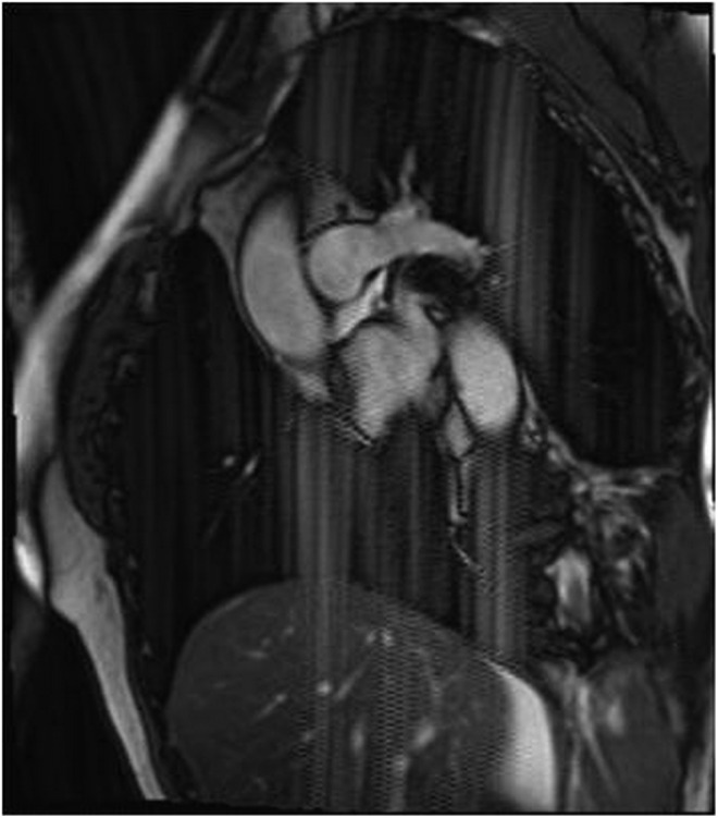
Zipper artefacts present as lines of electronic noise extending perpendicular to the frequency-encoding direction throughout the image series. A defective light was the cause. Another aspect is a sharp spike at the centre of the image.
Main magnetic field B0-related artefacts
Magnetic field inhomogeneities are frequently present owing to system imperfections and spatial variations in the magnetic susceptibility of the object. Small metallic objects (screws, paperclips) may also distort the main magnetic field. Field inhomogeneities can result in two different kinds of artefacts: geometric distortion and signal loss. The primary remedy of field inhomogeneity is setting of the shim coils and increasing the spatial resolution.3
Aliasing or wrap-around artefacts and zebra or Moire fringe artefacts
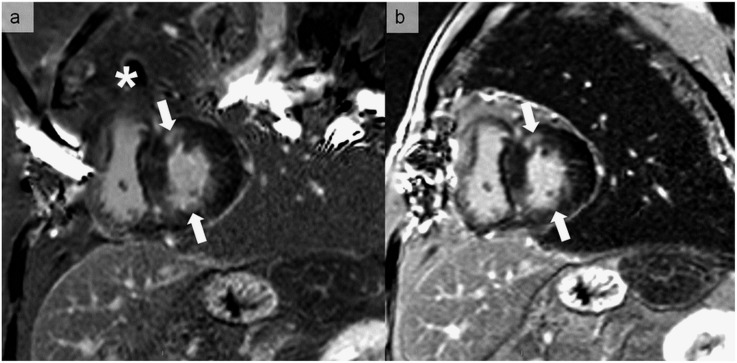
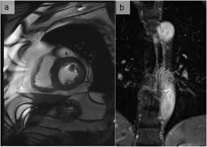
Aliasing artefacts (Figures 2 and 3) are seen most frequently in the phase-encoding direction. Aliasing artefacts combined with field inhomogeneity can lead to zebra artefacts or Moire fringes. Interference patterns due to field inhomogeneity appear as bright and dark bands at the periphery of the field of view (FOV).2 They may also appear in other locations owing to aliasing. These are commonly seen in gradient-echo images with the body coil (Figure 4). Oversampling of the imaged object is needed to avoid this type of artefact by increasing the FOV, using RF filters for cutting off frequencies outside the desired range or saturating the undesired tissue before acquisition.2,3
Figure 2.
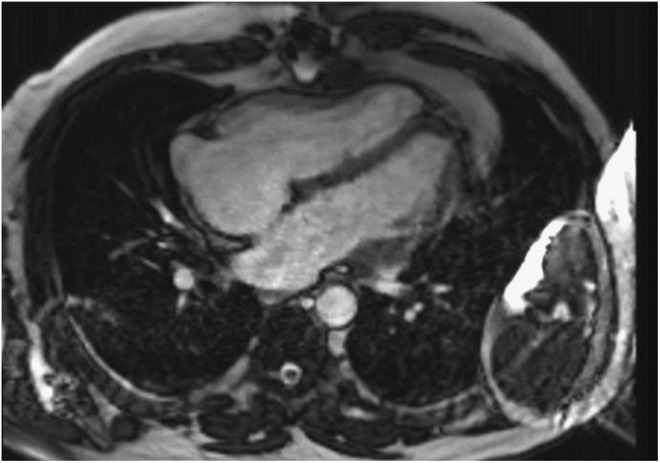
An aliasing or wrap-around artefact occurs because the imaged chest is larger than the field of view (FOV). It results in the projection of the right arm located beyond FOV boundaries on the left hemithorax.
Figure 3.
Late gadolinium enhancement images in the short-axis direction, showing two small fibrotic areas (arrows). (a) A large wrap-round artefact (asterisk) overlays the heart owing to reproduction of the anatomical structure outside the field of view in the phase-encoding direction. (b) The wrap-round artefact is placed outside the heart by changing the phase-encoding direction, resulting in a better quality and diagnostic image.
Figure 4.
Zebra artefacts appear as alternating curved bright and dark bands mainly at the periphery of the MR image (a). The inhomogeneity of the magnetic field combined with aliasing may also give rise to a centrally located artefact (b).
Magnetic susceptibility and metallic artefacts
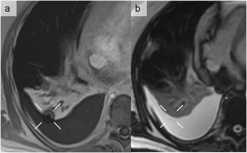
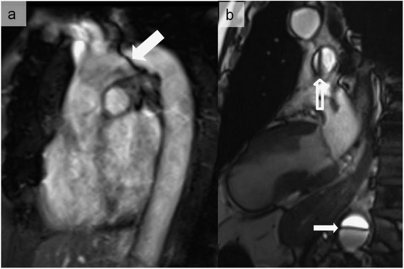
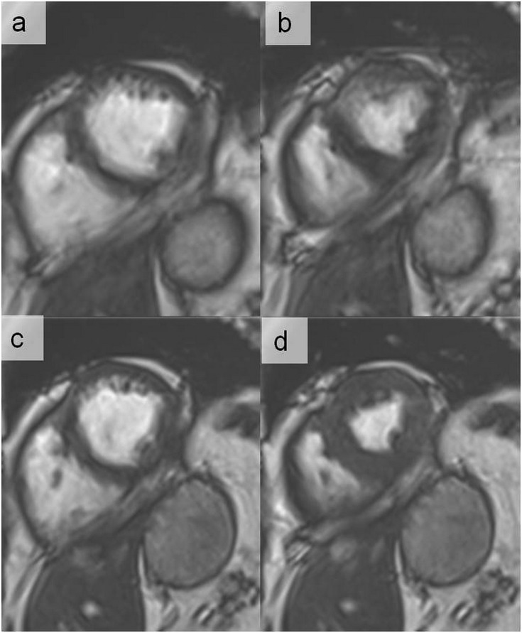
Juxtaposition of tissues with different magnetic susceptibilities causes intravoxel phase shifts, resulting in very dark and very bright regions.2,3 The susceptibility artefacts (Figure 5) represent a major concern at high magnetic fields (e.g. 3 T), particularly when using balanced steady-state free precession sequences (Figure 6) or when scanning patients with pacemakers5 or implantable cardioverter defibrillator (Figure 7). These artefacts can also be exaggerated when using single-shot echoplanar sequences and long echo times. Technical solutions include a better position of the shim and resonance frequency (“frequency scout”), the trade-off for a smaller voxel size and high bandwidth. Alternatively, the use of turbo spin-echo (Figure 8) or metal artefact-reduction sequences, including multiacquisition variable-resonance image combination and slice encoding for metal artefact correction sequences,6 is effective in minimizing this type of artefacts. With the new generation of MR-conditional pacemakers, high-quality images of the heart are obtained even for steady-state free precession acquisitions.5
Figure 5.
A round magnetic susceptibility artefact observed in a volumetric interpolated breath-hold sequence with gadolinium injection (a) that was not seen on a balanced steady-state free precession sequence (b). This artefact is projected on an underlying pleural effusion with alveolar consolidation of the right lower lobe.
Figure 6.
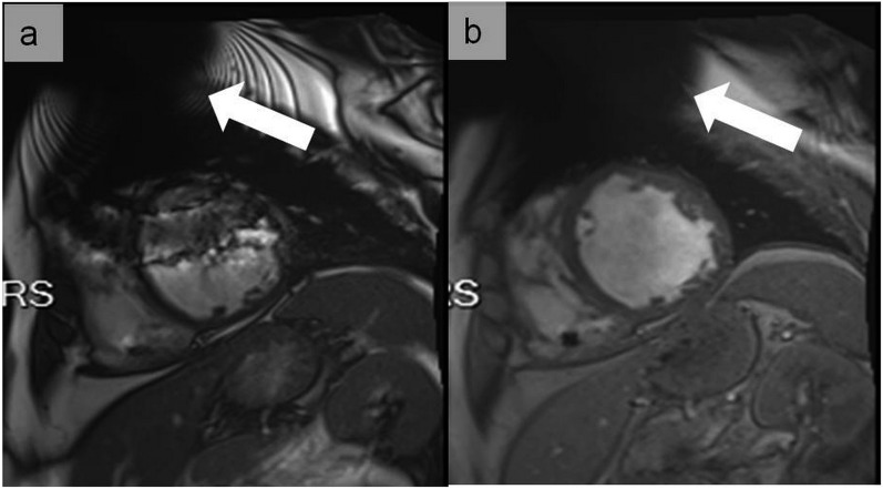
Magnetic susceptibility artefacts noticed during a balanced steady-state free precession sequence at 3 T, simulating an aortic dissection at the level of the aortic arch (a) (thick arrow). A pseudoflap appearance located in the descending aorta was also seen in another patient referred for cardiac MRI (b) (thin arrow). In (b), the artefactual nature was easily recognized owing to the same appearance in the pulmonary trunk (hollow arrow).
Figure 7.
Cine images at end-diastole in short-axis view at the mid-ventricular level using balanced steady-state free precession (a) and fast spoiled gradient echo (b) in a patient with an implantable cardioverter defibrillator. In (a), large dark band off-resonance and generator-related ferromagnetic susceptibility (arrow) artefacts hamper the image interpretation. In (b), dark band off-resonance artefacts are not any longer present and only the generator-related ferromagnetic susceptibility artefact is visible (arrow), resulting in good image quality adequate for clinical interpretation. The use of cine fast-spoiled gradient echo has the advantage of not being associated with dark band off-resonance artefacts.
Figure 8.
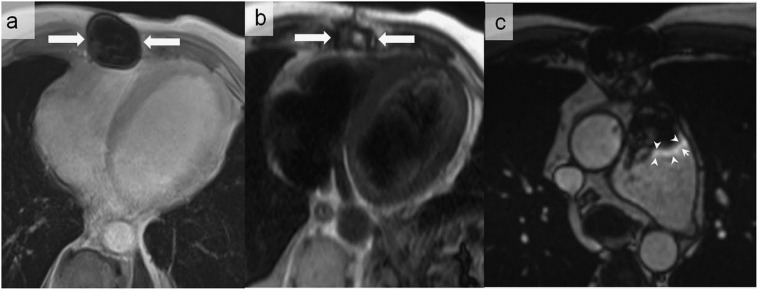
A 50-year-old male with congenital heart disease who underwent pulmonary valve replacement with biological valve prosthesis. Metallic artefacts related to sternotomy (arrows) are associated with total signal dropout on volumetric interpolated breath-hold sequence (a), but they are not any longer visualized on the half-Fourier acquisition single-shot turbo spin-echo sequence (b). Metallic artefacts may also appear as peripheral high signal intensity (arrowheads) (c).
Chemical shift artefact
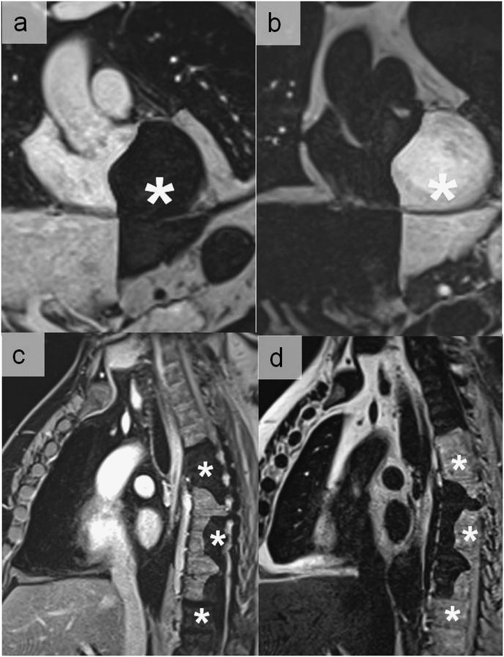
These artefacts are common and manifest as either bright and dark lines on both sides of fat–water interfaces (first type) or signal void in gradient recall-echo imaging (out of phase) (second type). Inherent differences in the precessional rates of fat and water in an applied magnetic field result in spatial shifts in the frequency-encoding direction.2,3 Worsened by increased field strength, these artefacts can cause a diagnostic dilemma when signals from the fat surrounding the thoracic aorta or within atheromatous plaque shift into the aortic lumen creating a pseudoflap appearance that may be misdiagnosed as aortic dissection.3 This type of artefacts can be minimized by enlarging the sampling bandwidth, applying a frequency-selective pre-saturation pulse for the adipose tissue, increasing the voxel size, choosing an echo time so that water and fat are in phase and switching phase-/frequency-encoding direction.2,3 Dual-echo Dixon's technique, a chemical shift-encoding technique which allows separating water and fat and ensures an excellent fat suppression with assessment of the spatial distribution of fat, can help recognize fat–water interfaces which generate artefacts. However, artefacts may also be created by using the Dixon technique (Figures 9 and 10).7
Figure 9.
Dixon artefacts most commonly related to a local swapping of water and fat signal which generates complementary geographic areas of signal void (asterisks). (a, c) Water images and (b, d) fat images.
Figure 10.
Dixon artefacts simulating pulmonary embolism visible on the water (a) and fat images (b) (arrows). The artefact disappeared in the opposition sequence (c). Although the quadrangular shape was suggestive of an artefact, CT pulmonary angiography (d) performed to definitely exclude this diagnosis was normal.
Truncation artefact (Gibbs phenomenon/ringing artefact)
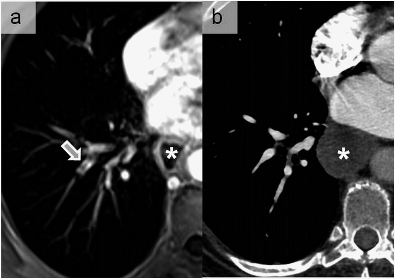
These artefacts occur near sharp image boundaries because of undersampling of high spatial frequencies, and they are observed both in phase- and frequency-encoding directions. They appear as successive bright and dark lines, such as a ripple (Figure 11). This artefact can be easily corrected by increasing the FOV matrix to extend the sampling range. Filtering of the k-space data before Fourier transform can also be used.2,6
Figure 11.
A truncation artefact appearing as central low signal intensity within the right laterobasal pulmonary artery (arrow) on contrast-enhanced pulmonary MR angiography (a). Such artefacts appear parallel to the abrupt transitions between regions of high and low signal intensities as in the case of opacified vessels. This was misdiagnosed as pulmonary embolism that was excluded by CT angiogram (b) performed following the MR examination. Note the dilated oesophagus in this patient with gastric bypass (asterisks).
PATIENT-RELATED ARTEFACTS
Motion artefacts
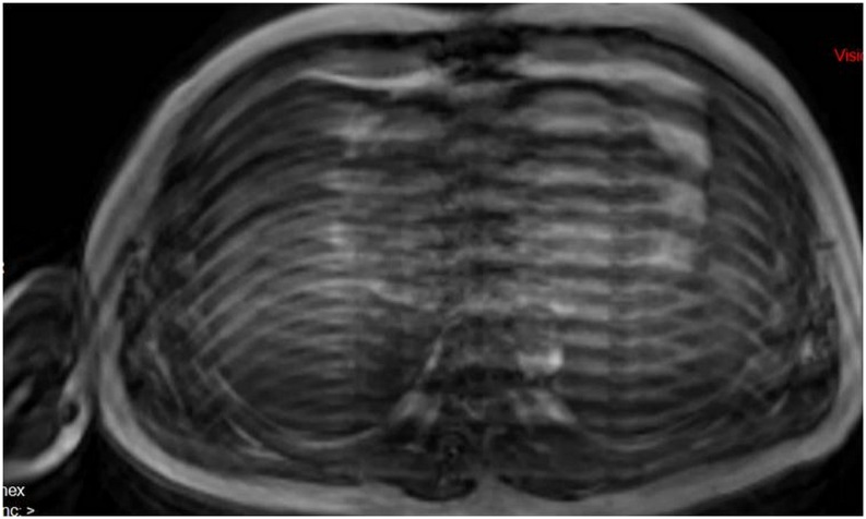
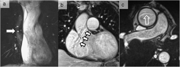
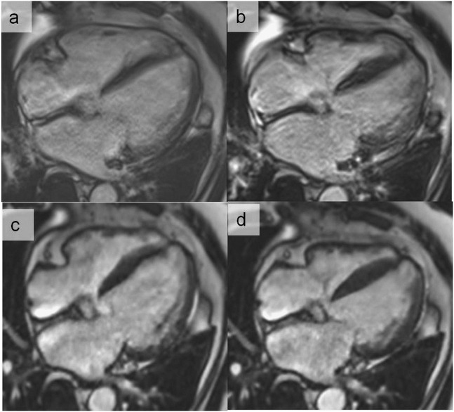
Motion artefacts in the chest can be categorized into three types: (1) patient voluntary movements, (2) physiological movements (such as the heartbeat and blood flow) and (3) breathing (Figure 12).3 Motion artefacts can cause either ghost images (Figures 13–15) or diffuse image blurring.2 For cardiac imaging, motion artefacts may occur in the case of irregular R–R interval owing to arrhythmias (Figures 16 and 17). Voluntary motion artefacts can be limited by clear instructions to patients (or patient sedation). Cardiac motion is eliminated by electrocardiogram triggering. Respiratory gating, fast imaging, breath-holding, reordering of phase-encoding (respiratory compensation) and saturation pulses can be used to reduce ghosting and blurring from respiration.2 Novel strategies are now under development exploiting compressed sensing techniques, allowing very fast image acquisition (acceleration in the order of 8–10-folds). These techniques have been shown to preserve image quality in cardiac imaging, even though some motion- and flow-related artefacts can occur.8
Figure 12.
Motion artefacts related to breathing.
Figure 13.
Ghost artefacts on the volumetric interpolated breath-hold examination sequence due to non-electrocardiogram, triggering generating alternative white and black curved lines parallel to the border of the ascending aorta (solid arrow) (a), right cardiac border (white arrows with black border) (b) and ascending aorta (open arrow) (c).
Figure 15.
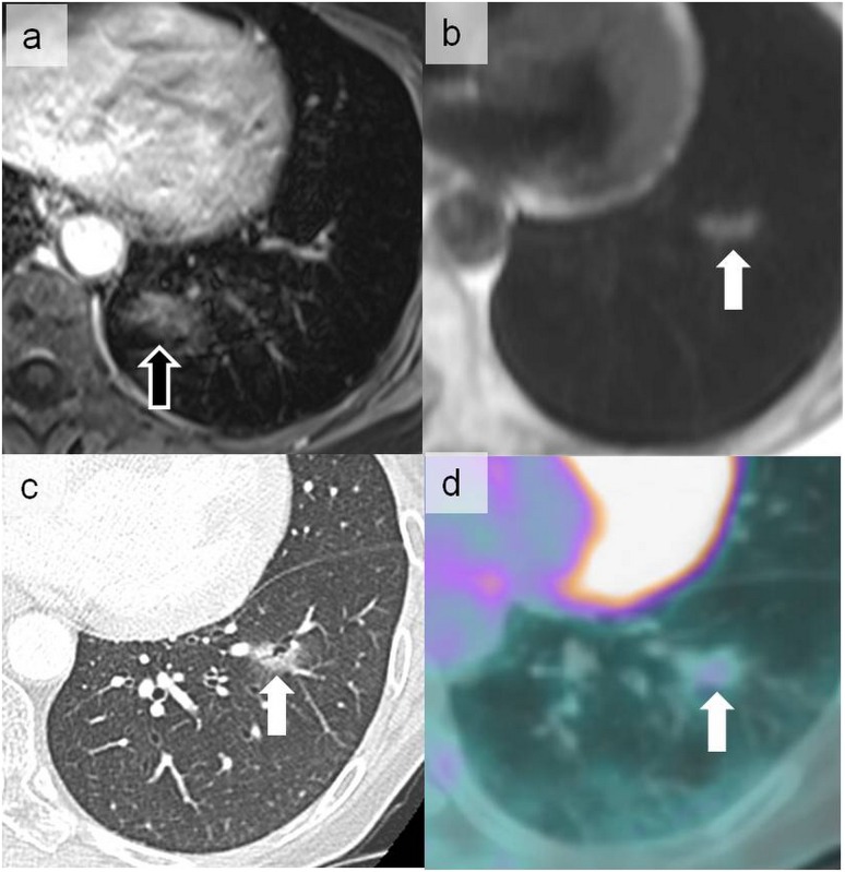
Cardiac ghost artefacts on the volumetric interpolated breath-hold examination sequence more prominent in the phase-encoding direction projecting posteriorly on the lung parenchyma (open arrow) (a). This should not be confused with the abnormal signal more laterally located in the left lower lobe on a half-Fourier acquisition single-shot turbo spin-echo sequence (solid arrow) (b). The latter signal corresponded to a ground-glass nodule on CT (c) metabolically hyperactive on positron emission tomography (d) that was related to pulmonary localization of a primary gastric lymphoma (arrows).
Figure 16.
End-diastolic (a) and end-systolic (b) cine images in the horizontal long-axis view using retrospective electrocardiogram gating in a patient with frequent ectopic ventricular beats. Using cross-validation-sparse (compressed sensing), the cine images are acquired in a single breath-hold heart beat, resulting in a significant improvement of image quality at end-diastole (c) and end-systole (d). The compressed sensing applies a compression algorithm during the acquisition process and then reconstructs the undersampled data with a novel non-linear reconstruction algorithm.
Figure 17.
End-diastolic (a) and end-systolic (b) cine images in a patient with atrial fibrillation (irregular R–R interval) using retrospective electrocardiogram (ECG) gating. With this method, the images are acquired continuously throughout the cardiac cycle over several (irregular) heart beats. Using prospective ECG triggering, the acquisition window is limited to the systolic phase (in this case, 350 ms after R-wave), partially avoiding the artefacts due to irregular R–R interval. This approach results in a better image quality at end-diastole (c) and end-systole (d) and throughout the imaged cardiac cycle.
Figure 14.
A ghost artefact of the ascending aorta (arrows) in the sagittal oblique plane (a) that should not be confused with a real chronic dissection of the descending aorta as seen in sagittal and axial planes (b) in this 44-year-old male with Marfan syndrome.
Flow artefacts
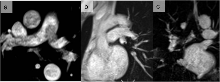
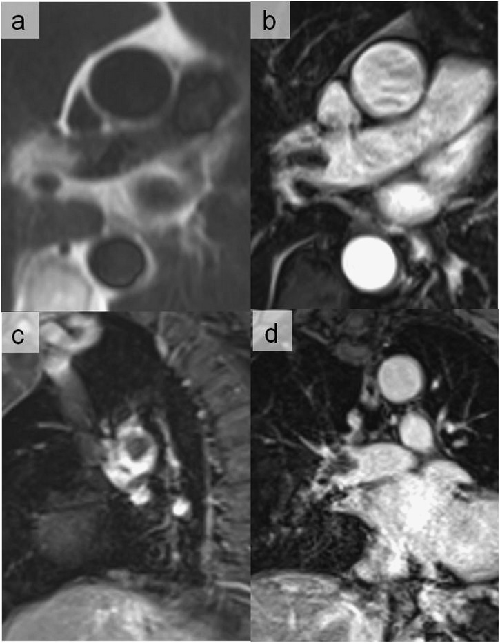
Blood flow artefacts are considered as a special subgroup of motion artefacts. Low signal intensities within vascular structures (Figures 18–20) can be explained by a high velocity flow, intravoxel phase dispersion or saturation from a previous RF pulse in gradient-echo sequences. Conversely, intravascular high signal intensities may be produced by high-velocity blood flow in gradient-echo sequences as well as by unsaturated intravascular spins (i.e. entry-slice phenomenon). Vessel pulsatility may also be involved in spatial misregistration or ghost images. These artefacts can be reduced by reduction of phase shifts with flow compensation, suppression of the blood signal with saturation pulses parallel to the slices and with electrocardiogram triggering.3
Figure 18.
Flow artefacts generating a signal loss in the pulmonary trunk and the left main pulmonary artery on the axial image of the volumetric interpolated breath-hold sequence (a) disappearing on the sagittal oblique image (b) and coronal views (c).
Figure 20.
Abnormal signal in the interlobar artery on half-Fourier acquisition single-shot turbo spin echo (a) confirmed as pulmonary embolism on axial (b), sagittal (c) and coronal volumetric interpolated breath-hold examination sequences (d). For each abnormal signal intensity seen on one plane or sequence, its presence should always be confirmed on other planes and sequences.
Figure 19.
Flow artefacts observed in the half-Fourier acquisition single-shot turbo spin-echo sequence simulating aortic dissection (a) and pulmonary embolism (c) that disappeared on volumetric interpolated breath-hold examination sequences (b, d). These artefacts are mainly related to the axial orientation of the aortic arch and left main pulmonary artery when performing dark-blood double inversion-recovery pulse sequence. A perpendicular black-blood sequence to these vessels could also suppress these artefacts.
For comprehensive cardiac examinations, flow measurements are crucial to assess valves and congenital heart disease.9 For accurate measurements, it is important to place the vessel of interest at the centre of the magnetic field to minimize offsets in the background phase. In particular, eddy currents can cause considerable errors in velocity measurements. Accordingly, it is suggested to measure the background phase in the solid non-moving tissue nearby the vessel of interest (or in the chest wall as an alternative) to check for small background phase errors and to correct for if the background phase is considerably different from zero.10
CONCLUSION
Artefacts associated with cardiothoracic MR are of wide variety; recognizing them is the radiologist's responsibility. Our article gives a short review of the most common current artefacts encountered during cardiothoracic MR, their appearances, origins and possible solutions. Nevertheless, the best way to reduce or eliminate the artefacts and improve the image quality is through knowledge of all MRI artefacts and familiarity with the MR machine in the radiology department.
Teaching points
Magnetic susceptibility artefact is confusing when using balanced steady-state free precession sequences at 3 T, generating off-resonance artefacts that may simulate an aortic dissection.
Chemical shift artefacts can cause a diagnostic problem when signals from the fat surrounding the thoracic aorta or within atheromatous plaque shifts into the aortic lumen that may be misdiagnosed as aortic dissection.
Truncation of signal may manifest as misleading central signal intensity dropouts in lobar or segmental pulmonary artery vessels, which can be mistaken as pulmonary embolism.
Flow measurements are crucial to assess valves and congenital heart disease. For accurate measurements, it is required that the vessel of interest be placed at the centre of the magnetic field to minimize offsets in the background phase. In particular, eddy currents can cause considerable errors in velocity measurements. Accordingly, it is suggested to measure the background phase in the solid non-moving tissue nearby the vessel of interest to check for small background phase errors and to correct for if the background phase is considerably different from zero.
Acknowledgments
ACKNOWLEDGMENTS
The authors thank Dr Pierre Monney, MD (Division of Cardiology, Department of Internal Medicine and Cardiac MR Center of the University Hospital Lausanne, Switzerland) and Pascal Chèvre (SIEMENS company) for their advice and support.
Contributor Information
Khalid Alfudhili, Email: drkmf@hotmail.com.
Pier G Masci, Email: pgmasci@gmail.com.
Jean Delacoste, Email: jean.delacoste@chuv.ch.
Jean-B Ledoux, Email: jean-baptiste.ledoux@chuv.ch.
Grégoire Berchier, Email: gregoire.berchier@chuv.ch.
Vincent Dunet, Email: vincent.dunet@chuv.ch.
Salah D Qanadli, Email: salah.qanadli@chuv.ch.
Juerg Schwitter, Email: jurg.schwitter@chuv.ch.
Catherine Beigelman-Aubry, Email: catherine.beigelman-aubry@chuv.ch.
REFERENCES
- 1.Klinke V, Muzzarelli S, Lauriers N, Locca D, Vincenti G, Monney P, et al. Quality assessment of cardiovascular magnetic resonance in the setting of the European CMR registry: description and validation of standardized criteria. J Cardiovasc Magn Reson 2013; 15: 55. doi: 10.1186/1532-429X-15-55 [DOI] [PMC free article] [PubMed] [Google Scholar]
- 2.Stadler A, Schima W, Ba-Ssalamah A, Kettenbach J, Eisenhuber E. Artifacts in body MR imaging: their appearance and how to eliminate them. Eur Radiol 2007; 17: 1242–55. doi: 10.1007/s00330-006-0470-4 [DOI] [PubMed] [Google Scholar]
- 3.Schiebler ML, Listerud J. Common artifacts encountered in thoracic magnetic resonance imaging: recognition, derivation, and solutions. Top Magn Reson Imaging 1992; 4: 1–17. doi: 10.1097/00002142-199206000-00004 [DOI] [PubMed] [Google Scholar]
- 4.Bruder O, Wagner A, Lombardi M, Schwitter J, van Rossum A, Pilz G, et al. European Cardiovascular Magnetic Resonance (EuroCMR) registry—multi national results from 57 centers in 15 countries. J Cardiovasc Magn Reson 2013; 15: 9. doi: 10.1186/1532-429X-15-9 [DOI] [PMC free article] [PubMed] [Google Scholar]
- 5.Schwitter J, Kanal E, Schmitt M, Anselme F, Albert T, Hayes DL, et al. Impact of the Advisa MRI pacing system on the diagnostic quality of cardiac MR images and contraction patterns of cardiac muscle during scans: Advisa MRI randomized clinical multicenter study results. Heart Rhythm 2013; 10: 864–72. doi: 10.1016/j.hrthm.2013.02.019 [DOI] [PubMed] [Google Scholar]
- 6.Erasmus LJ, Hurter D, Naudé M, Kritzinger HG, Acho S. A short overview of MRI artefacts. S Afr J Radiol 2004; 8: 13–7. doi: 10.4102/sajr.v8i2.127 [DOI] [Google Scholar]
- 7.Eggers H, Bornert P. Chemical shift encoding-based water-fat separation methods. J Magn Reson Imaging 2014; 40: 251–68. doi: 10.1002/jmri.24568 [DOI] [PubMed] [Google Scholar]
- 8.Vincenti G, Monney P, Chaptinel J, Rutz T, Coppo S, Zenge MO, et al. Compressed sensing single-breath-hold CMR for fast quantification of LV function, volumes, and mass. JACC Cardiovasc Imaging 2014; 7: 882–92. doi: 10.1016/j.jcmg.2014.04.016 [DOI] [PubMed] [Google Scholar]
- 9.Schwitter J, editor. CMR-update . 2nd edn. Lausanne, Switzerland: Schwitter J; 2012. [cited November 2015.] Available from: www.herz-mri.ch [Google Scholar]
- 10.Ferreira PF, Gatehouse PD, Mohiaddin RH, Firmin DN. Cardiovascular magnetic resonance artefacts. J Cardiovasc Magn Reson 2013; 15: 41. doi: 10.1186/1532-429X-15-41 [DOI] [PMC free article] [PubMed] [Google Scholar]


