Abstract
A new wireless electrophysiology data acquisition system, built around a standard homecage, is presented in this paper, which can power up and communicate with sensors and actuators/stimulators attached to or implanted in small freely behaving animal subjects, such as rodents. Key abilities of the energized homecage (EnerCage) system is enabling longitudinal experiments with minimal operator involvement or interruption, while providing test subjects with an enriched environment closer to their natural habitat, without the burden of being tethered or carrying bulky batteries. The magnetic resonant multi-coil design used in the new EnerCage-HC2 automatically localizes the transmitted electromagnetic power from a single transmitter (Tx) coil at the bottom of the cage toward the receiver coil (Rx), carried on/in the animal body, obviating the need for tracking the animal or switching the coils. In order to increase the resonators’ quality factor (Q > 166) at the desired operating frequency of 13.56 MHz, while maintaining a high self-resonance frequency (SRF > 42 MHz), they are made of wide copper foils and optimally segmented based on a set of design rules that can be adopted for experimental arenas with different shapes and dimensions. The Rx rectified voltage is regulated at a user-defined window (4.1 ± 0.3 V) by a Tx-Rx closed-loop power control (CLPC) mechanism that creates a volume inside the homecage with 42 mW of power delivered to the load (PDL), and a homogeneous power transfer efficiency (PTE) plane of 14% on average at ~7 cm height, plus stability against angular misalignments of up to 80°.
Index Terms: Inductive wireless power transmission (WPT), close loop power control, homecage, enriched environments, awake freely behaving animals
I. Introduction
A large majority of today’s basic science and preclinical research experiments are conducted on small vertebrates, such as rodents. According to one estimate, in 2001, about 80 million mice and rats were used for animal experiments in the U.S. alone [1]. A significant number of these experiments are conducted on awake behaving animal subjects to control the variables that affect the behavior or biological system under study. They often require detailed preparations to monitor vital signs, behaviors, phenotypes, and physiological parameters with sensors that are either installed around the experimental arena or attached to or implanted in the animal body. There are also in vivo experiments that involve interventions, such as stimulation or drug delivery, which follow a similar routine after the surgical procedure for sensor, electrode, actuator, or conduit placement: 1) transfer the animal subjects from their homecage in the animal facility to the experimental arena, 2) attach cables, connectors, reservoirs, or wireless modules, 3) closely observe the animal behavior during the training or data collection period, 4) detach everything from the animal, and 5) return them back to the homecage in the animal facility [2]. This routine needs to be repeated for every single session and every subject, creating a stressful environment for the animal subjects that can bias their behavior and experimental results [3]. It is also quite labor intensive and time consuming for the researchers in long-term experiments, and impose significant financial burden on the research institutions, driving the costs up, if they are outsourced to contract research organizations (CRO). Similarly, testing early stage new drugs or medical devices under development in terms of efficacy, safety, reliability, and biocompatibility, involves experiments that run over extended periods in large animal subject populations to achieve reliable and meaningful statistical outcomes. If any portion of the aforementioned procedure can be shortened or automated, it can have a significant impact on the quality of the experimental results and reduction in costs and labor.
There is a large body of research that signifies the effects and importance of the environmental enrichment in behavioral neuroscience [4], [5]. For instance, Simpson and Kelly found that enrichment has profound effects on brain neurochemistry and the resulting behavior, suggesting that environmental enrichment has the potential to significantly modify these parameters in rats. They also identified the duration of the enrichment as one of the important variables in its impact [3].
We have developed a comprehensive EnerCage system with a modular architecture that can alleviate limitations over the size and shape of the experimental arena as well as the duration of the experiment [6], [7]. In this system the animal subject was tracked in real time using a small magnetic tracer on the animal body and an array of 3-axial magnetic sensors embedded in the Tx coil tiles at the bottom of the arena. We noticed that the number of experiments limited by tethering effect and operating time of the existing hardwired and wireless systems, respectively, is much higher than those limited by the size of the experimental arena. Therefore, we developed a new EnerCage system architecture around the most common experimental spaces in today’s research labs, i.e. the standard homecage [8]. EnerCage-HC1, however, still required the animal subject to be tracked in real time using a Kinect® 3D image sensor mounted above the homecage. This would occupy space and prevent the homecage from being placed in a rack, which is quite common in animal care facilities. In the meantime, several other groups have developed their own wirelessly-powered cages in various dimensions, all of which required animal tracking [9]–[12] except for a recent high frequency design [13], which is only suitable for delivering small power level (< 1 mW) due to safety limits, and requires a large RF cavity underneath the cage, preventing it from placement in a rack. Using ultrasonic energy to transfer power has also been proposed [14], [15]. However, it is mostly suitable for powering implantable medical devices as ultrasound requires tissue medium for energy transfer, and significantly attenuates in the air. Therefore, it is not suitable for powering a headstage on a freely behaving animal.
Here we present a new EnerCage system (HC2), built around a standard homecage, which can continuously power up and communicate with any sensors, stimulators, actuators, and their associated electronics implanted in or carried on the animal body in the near-field regime at the FCC-approved operating frequency of 13.56 MHz in the industrial, scientific, medical (ISM) band, which allows delivering high power levels to the load (PDL) in 10s of mW range, while reducing the risk of interference with nearby instruments or excessive heat and electromagnetic exposure to the animal subjects in the cage and research personnel. The novel multi-resonator coil arrangement around the homecage, simply driven by a single LC-tank located at the bottom of the homecage, can dynamically focus the magnetic field at the position of the Rx coils in/on the animal body, obviating the need for a tracking system or switching the coils. Moreover, in order to increase the resonators’ quality factor (Q) at 13.56 MHz, while maintaining a high self-resonance frequency (SRF), they are made of wide copper foils and optimally segmented to achieve a homogeneous power transfer efficiency (PTE), i.e. with the highest possible minimum, at the nominal height of the designated animal species (~7 cm for rats). Furthermore, a closed-loop power control (CLPC) mechanism is established between the Tx-Rx power management circuits to cover the entire volume inside the homecage with stable and robust PDL at a user-defined level despite animal movements.
The following section presents the EnerCage-HC2 system overview. Section III describes the design, optimization, and analysis of the copper-foil segmented coils, as well as HFSS simulation results. Section IV includes the measurement results, followed by the concluding remarks.
II. EnerCage-HC2 System Overview
Fig. 1 shows a simplified block diagram of the EnerCage-HC2 system, which provides a small receiver carried by the behaving animal subject in the form of a headstage (in this case), backpack, or implant, with wireless power via magnetic resonance in the near field through a multi-coil inductive link. It can also communicate with the receiver wirelessly through a Bluetooth low energy (BLE) link to enable remote control of the electronics, acquire data, and CLPC.
Fig. 1.
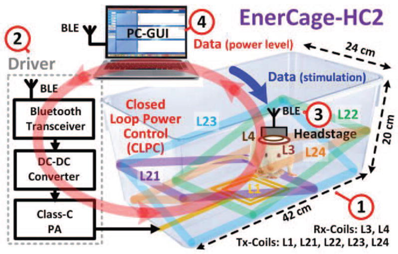
A simplified conceptual representation of the proposed EnerCage-HC2 system for closed-loop wireless powering of a headstage or implant on/in an awake freely behaving small animal body for continuous long term stimulation, recording, or drug delivery within a standard homecage.
The EnerCage-HC2 consists of four major blocks: 1) A standard 20 (H)× 23 × 45 cm3 rodent homecage (bottom of the cage is 20 × 42 cm2), made of polycarbonate (Alternative Design, Siloam Springs, AR), which is encompassed by five primary coils that constitute the power Tx. L1 is the only coil that is driven by a Class-C power amplifier (PA). The other four coils, L21–L24, are electrically floating tilted primary resonators, made of 25 mm wide copper foil, segmented to achieve high Q-factor without reducing SRF. They adhere to the body of the homecage along with their resonance capacitors from outside (see Fig. 5), and are covered with Kapton® tape (polyimide film) for electrical isolation from one another and protection against moisture. 2) A driver block that includes the Class-C PA, operating at 13.56 MHz, a digitally controlled DC-DC converter that can adjust the PA supply voltage to change its output power, controlled by a CC2540 microcontroller (MCU) (Texas Instruments, Dallas, TX) with built-in BLE transceiver. 3) A headstage that includes the secondary resonator, L3C3, and the load LC-tank, L4C4, plus additional circuits to support sensing, stimulation, or drug delivery. The headstage is also equipped with a CC2541 to establish a bidirectional BLE communication link with; 4) A personal computer (PC), equipped with a CC2540 MCU dongle, which monitors the CLPC function, stores acquired data from the headstage, sends control commands to the headstage, and shows the status of the EnerCage-HC2 system in real time through a graphical user interface (GUI).
Fig. 5.
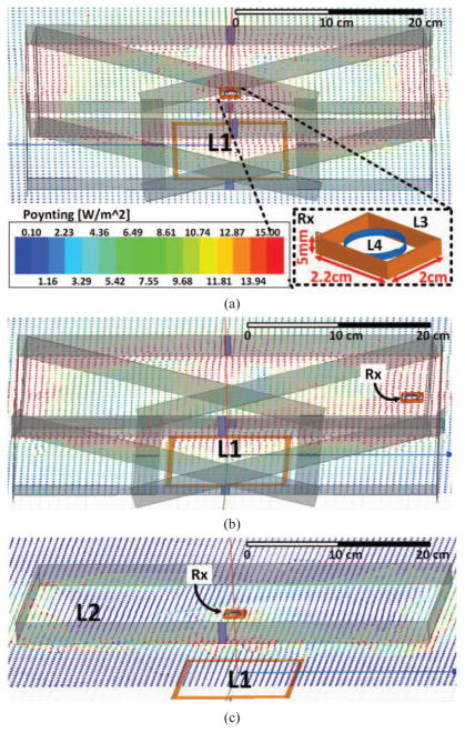
Poynting vector simulations in HFSS when the Rx is located at the (a) center and (b) right side of the homecage, 7 cm from the bottom of the cage. (c) Similar simulation with a single horizontal Tx resonator (L2) at 7 cm.
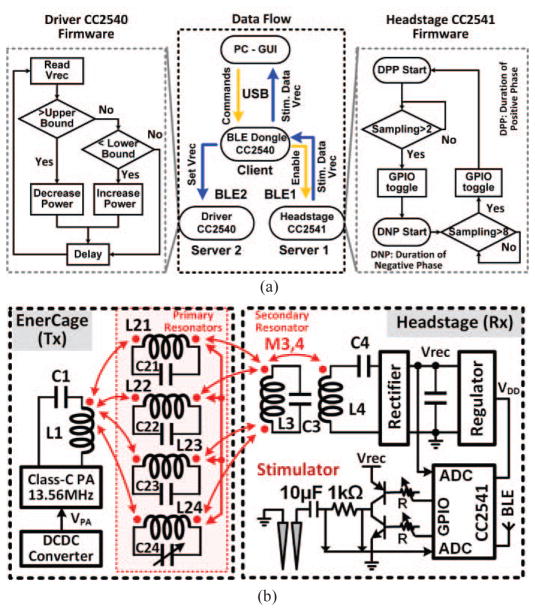
Fig. 2a shows a simplified flowchart of the CLPC, which includes two BLE links among three aforementioned CC254X MCUs. Upon receiving the user command, the GUI first establishes a BLE connection between the PC dongle (master) and the headstage MCU (slave), and then establishes a second connection between the PC dongle (master) and the driver MCU (slave), which are referred to as the BLE1 and BLE2 links, respectively. Once BLE1 is in place, the CC2541 builtin ADC in the headstage samples the onboard rectifier output voltage, Vrec, which is made of Schottky diodes (BAS4002A, Infineon Technologies, Germany) to reduce dropout voltage, as well as the stimulus current across a 1 kΩ resistor at 100 Hz each, and sends them to the PC to be recorded and visualized on the GUI. The CLPC algorithm running on the PC compares Vrec with the desired window, defined by the user, and delivers this information to the driver block via BLE2. The driver MCU, which controls the DC-DC converter, increases or decreases the PA supply voltage, VPA, based on the incoming Vrec data in a closed-loop to ensure that it remains within the desired range despite animal movements or load variations.
Fig. 2.
a) Simplified flowchart of the close-loop power control (CLPC) mechanism, as implemented in the firmware among three CC2541 microcontrollers with built-in BLE. b) Schematic diagram of the key circuits involved in the wireless power transmission in the EnerCage-HC2 system. Red arrows indicate mutual coupling among various coils on the primary (Tx) and secondary (Rx) sides.
III. Designing the Segmented Coils
In this section a set of rules governing the design of the EnerCage-HC2 coils and resonators is presented, which support the choice of resonance frequency, geometry of the coils on the Tx and Rx sides, and segmentation of the primary resonators. Fig. 2b shows the schematic diagram of the main circuits involved in the wireless power transmission from the homecage driver to the neural tissue in the case of a wireless stimulating headstage. The red arrows in this figure indicate mutual coupling among various coils on the Tx and Rx sides, where the Tx coils form a symmetrical arrangement with respect to the center of the homecage (see Fig. 1). In Fig. 3a, the Tx resonators are divided into two groups which are rotated 90° with respect to one another: (L21–L22) and (L23–L24). To simplify the theoretical analysis and without loss of generality, we look at only one group of resonators at a time and infer the effect of the other group based on symmetry. For simulations and measurements, however, we consider both groups together to demonstrate their agreement.
Fig. 3.
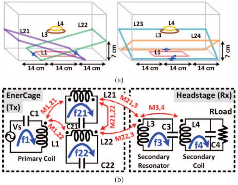
a) The conceptual schematics of primary resonators’ implementation into two figures to avoid making it busy, and b) the equivalent circuit model of the proposed inductive link including only two primary resonators for simplicity.
A. A Single Resonance Frequency for the Entire System
As fundamental requirement in geometric design of the EnerCage-HC2 was to make ensure that the collective Tx-Rx inductive link structure produces a single resonance frequency, and that would be tuned to match the carrier frequency generated by the driver block. This requirement can be mathematically incorporated in the equations that indicate the resonance frequency of each resonator in the inductive link chain, as shown in the simplified Fig. 3b, while considering all the mutual inductances that affect it. Fig. 3b shows the mutual couplings among the coils in the simplified structure and their respective resonance frequencies, which can be found from,
| (1) |
| (2) |
| (3) |
| (4) |
| (5) |
Since L1, L21, and L22 are stationary around the homecage, M1,21, M1,22 and M21,22 are constant. M3,4 is also constant since L3 and L4 are fixated in the headstage, even though the headstage moves within the EnerCage-HC2. Thus the only mutual inductances in (1)–(5) are M21,3 and M22,3, which are very small in comparison to the other mutual inductances because of the large separation and size difference between the Tx and Rx coils. Hence, a single target resonance frequency for this system can be set, regardless of the Rx location in the homecage, and each of the LC-tank resonance frequencies can be tuned to match the carrier frequency (f = 13.56 MHz) by changing its respective capacitor. From the practical and convenience perspectives, it is worth nothing that in this design, because of the strong coupling among the primary resonators due to their overlap, only one primary resonator needs to be finely tuned to match the resonance frequency of the entire Tx structure with the target carrier frequency, f.
B. Geometrical Design of the Inductors
Key factors in determining the coil geometries in EnerCage-HC2 system were: 1) Compatibility with standard homecage dimensions that are used for rodents, particularly within a rack. 2) Providing maximum PTE and sufficient PDL to the Rx, particularly in the worst case conditions, i.e. without holes or deep valleys in the wirelessly powered areas within the homecage. As shown in Fig. 3b, a voltage source, Vs (PA), pumps electric power into L1 on the Tx side, generating a homogeneous electromagnetic filed across the homecage with the help of four Tx resonators, inducing current in the Rx resonator, L3C3, located at a nominal height of d from the bottom of the homecage and eventually in L4, which delivers power to RL. It should be noted that optimizing the PTE and PDL in this case means elevating them in areas with minimum PTE to ensure PDL is enough to keep the Rx on when the CLPC adjusts the Tx power, as opposed to maximizing PTE in the perfectly aligned regions in traditional coil optimization.
We were able to shrink the size of the headstage PCB, which houses part of the CLPC and a simple 1-ch discrete stimulation circuit in this version (see Fig. 2b), down to 1.8 × 2 cm2. The size of this PCB defined dimensions of L3, which was made of a 5 mm-wide copper foil encompassing the headstage circuitry in a 2.2 × 2 × 0.5 cm3 cube (see Fig. 10b). L3 was made of a copper foil to increase its Q-factor, Q3, by reducing its parasitic resistance with minimum impact on the weight and volume of the headstage. The nominal distance of the Rx from the bottom of the homecage, d, depends on several factors, such as the anatomical position of the Rx and average size, age, and strain of the animal species. In the case of a headstage, considering the average height of the top of a Sprague Dawley rat’s head when it is walking on four limbs (~6 cm), plus the 1.1 cm length of the stimulating electrode connector (Electrophysiology Cable 305/CP, PlasticsOne, Roanoke, VA) used to mount the headstage on top of the rat head (see Fig. 10b), resulted in nominal d ≈ 7 cm.
Fig. 10.
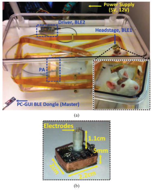
(a) In vivo experimental setup with freely behaving rats and a 1-ch wireless stimulating headstage to test the EnerCage-HC2 system operation, particularly the CLPC. (b) Close up view of the headstage and its dimensions.
Based on our prior simulations and in vitro experimental results on the EnerCage-HC1 system [8], since the size of the Rx coils is considerably smaller than the homecage, the center of the cage often has the weakest magnetic flux density, mutual coupling, and consequently the PTE. Therefore, we start designing the Tx coils by optimizing the PTE between L1, which is placed under the center of the cage, and perfectly aligned L3. From [16]–[18], if dR and dT are the diameters of perfectly aligned circular Rx and Tx coils separated by d, respectively, the optimal PTE can be achieved when,
| (6) |
If Tx and Rx coils are not circular, we can still use (6) by multiplying both sides by π/4 to consider the coils’ areas,
| (7) |
| (8) |
where AT and AR are the areas of the Tx and Rx coils, respectively. Using (8) for a pair of rectangular coils and plugging in L3 dimensions, the optimal size for L1 was calculated as 13.45 cm, and rounded up to 13 cm. We used 15 AWG magnet wire, made of copper with varnish coating, to construct L1. Following the optimization procedure in [19] for 3-coil inductive links, we derived the number of turns for L1 and L3 to be N1 = 3 and N3 = 3, respectively, as well as the specifications of L4 in the headstage. These specifications are summarized in Table I.
Table I.
Specifications of the Implemented Coils
| Parameter | L1 | L21 L22 | L23 L24 | L3 | L4 |
|---|---|---|---|---|---|
| Inductance, L (μH) | 5.46 | 0.88 | 0.94 | 0.7 | 0.9 |
| Quality Factor, Q | 116 | 166 | 160 | 182 | 138 |
| Outer diameter, do (mm) | 13 | 33×22 | 43×22 | 2×2.2 | 1.6 |
| Inner diameter, di (cm) | 12.8 | 30×22 | 43×20 | 1.8×2 | 1.1 |
| Conductor width, W (mm) | - | 25 | 25 | 4 | - |
| Thickness, T (um) | - | 89 | 89 | 89 | - |
| Diameter, (mm) | 1.45 | - | - | - | 0.4 |
| Number of turns, N | 3 | 1 | 1 | 3 | 6 |
| Type of coil | AWG 15 | Foil tape | Foil tape | Foil tape | AWG 26 |
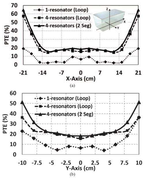
If we were to add a single high-Q resonator, L2, to L1, L3, L4 combination to improve the PTE around the perimeter of the homecage in a 4-coil arrangement, the best positon would have been a horizontal resonator at the nominal height of d = 7 cm [20]. We constructed a 3D model for this arrangement in the HFSS environment (ANSYS, Canonsburg, PA) to validate and fine tune the design of the multi-coil Tx. The dotted curves in Fig. 4 show the resulting PTE when Rx is swept along X and Y axes. Even though L2 significantly improves the PTE around the perimeter of the homecage, due to the weak coupling between L1 and L2, resulting from their disparate dimensions, the PTE is quite low in areas outside L1 but not close to the perimeter of the homecage. To improve the mutual coupling between L1 and L2, while maintaining strong magnetic field density around the perimeter of the homecage at the height of 7 cm, we used four rectangular resonators, L21–L24, each covering one side of the homecage at d = 7 cm, and slanted towards L1 on the other side to go around L1 in proximity of its windings. This arrangement not only strengthens M1,21–24 in Fig. 3 but also help the system to be more robust against Rx angular misalignments. The distance between the two sides of L21 and L22 along X-axis and L23 and L24 along the Y-axis across L1 is 15 cm. A similar HFSS simulation in Fig. 4 (the dashed lines) show a significant improvement in the PTE both in the center and along the perimeter of the homecage, while also eliminating the areas with weak PTE, to ensure PTE > 14% anywhere within the EnerCage-HC2 system.
Fig. 4.
Simulated PTE inside the EnerCage-HC2 using HFSS for 25 mm-wide copper foil including one horizontal loop resonator, four loop resonators, and four 2-segment resonator designs, when the Rx is swept across (a) X axis (Y = 0 cm), and (b) Y axis (X = 0 cm), at the height of d = 7 cm.
C. Segmentation of the Tx Resonators
Considering the large dimensions of the Tx resonators, as they need to wrap around the homecage, and the choice of a relatively high operating frequency, f = 13.56 MHz, to be within the ISM band, using the existing RFID chipsets, and shrinking the size of Rx components, it is important to make sure that the SRFs of L21–L24 are considerably higher than f. Otherwise, Q21–Q24 would drop and significantly degrade the PTE [21]. One well-known method for increasing the SRF of large coils, which is often used in design of the magnetic resonance imaging (MRI) systems, is segmentation [22]. In this method, the large highly conductive loop is divided into equal-length segments linked with small capacitors in a way that the length of each segment is much less than the wavelength of the carrier signals [23]. This is done to avoid electromagnetic field cancellation at the Rx location, caused by the varying current phase in a large conductive loop [24]–[26], where the field is stronger close to the perimeters of the loop where the conductors are. With proper segmentation, however, the loop is able to produce a uniform magnetic field distribution by avoiding current phase cancelation in the center, where we often have the weakest magnetic field.
The relative permittivity of polycarbonate, the material used in the body of the EnerCage-HC2 prototype, which constitutes the substrate for the Tx resonators, is εr = 3 [27]. This will result in a wavelength of , indicating that a suitable choice for the length of each segment would be less than λeff = λ/10 = 1.3 m [23], [24], [28]–[30]. On the other hand, the perimeters of the Tx resonators (L21–L22) and (L23–L24) in Fig. 3a are 1.1 m and 1.3 m, respectively. Thus, the Tx resonators were segmented only by two to make sure the segmentation rule is satisfied. To validate the optimal number of segments in the Tx resonators, we compared the PTE in the same HFSS model, resulting in the curves with the solid lines in Fig. 4, which confirmed that 2-segment resonators were slightly better than complete loops. Table I includes the final specifications of the Tx resonators (also see Fig. 6).
Fig. 6.
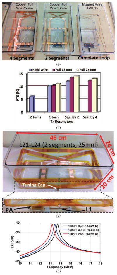
(a) Fabricated prototypes of the EnerCage-HC2 systems to find the best Tx resonator option. (b) PTE measurements within the EnerCage-HC designs in (a) with the Rx at d = 7 cm. (c) The final design of the EnerCage-HC2 in which the Tx resonators are made of 25 mm copper foil, segmented-by-two, with L1 and PA located at the bottom of the homecage. (d) S21 as a function of frequency for three values of the L24 resonator tuning capacitor, when all other Tx resonance capacitors are constant at 130 pF. Adjusting this capacitor alone tunes all the strongly-coupled Tx resonators.
D. Self-Localizing Effect
The proposed configuration of high-Q resonators around the homecage with their considerable overlap and strong cross-coupling results in self-localization of wireless power towards the Rx location. In particular, in this design all primary resonators have strong coupling with L1 by fully overlapping it. One or more resonators that are best coupled with the Rx is/are the resonator(s) that transfer power to L3 and L4. Therefore, at the cost of slightly lower PTE compared to the EnerCage-HC1 [8], which is compensated to a large extent by using higher-Q copper foil resonators (see Table II), no animal tracking or coil switching is required to active or deactivate the resonators that are closer to Rx. This will make the proposed solution more suitable for low-cost and high- throughput experiment designs, which can even be executed within the animal care facility, without occupying precious laboratory space. A similar method was recently reported in [31], in which the authors have physically connected all the Tx resonators in parallel with hardwires. This makes it more difficult to construct the resonators compared to the electrically floating approach adopted here. Our resonator design also leaves the top of the homecage open for easy access to proving water, food, and animal handling.
Table II.
Benchmarking EnerCage-HC2
| Ref. | [6] | [8] | [11] | [31] | [20] | This work |
|---|---|---|---|---|---|---|
| Type of wireless link | 4-coil | 3/4-coil | 2-coil | 4-coil | 4-coil | 4-coil |
| Operating frequency f (MHz) | 13.56 | 13.56 | 13.56 | 13.56 | 2.45 | 13.56 |
| Size (cm2) | 50×60 | 30×30 | 18×34 | 27×27 | 29×20 | 24×46 |
| Powering distance d (cm) | 12 | 7 | 3 | 1–15 | 1.5 | 0–17 |
| Rx diameter (cm) | 4 | 2.5 | 1.2 | 2 | 2 | 2.2 |
| Minimum PTE | 5% | 16.1% | 4.7% | - | - | 14% |
| Average PTE | 19.6% | 21.9% | 17% | 20% | 25.9% | 18% |
| Maximum rotation θ | 60° | 60° | - | 30° | - | 80° |
| PDL-AC (mW) | 20 | 24 | 1.2 | 36 | 43 | 65 |
| CLPC | Yes | Yes | No | No | No | Yes |
Fig. 5 shows the Poynting vectors generated by our 3D HFSS models, which illustrate the real part of the power density. These simulations show how electromagnetic power is coupled from the Tx resonators around the homecage to the Rx coils, located at 7 cm above of the bottom of the cage. Fig. 5a shows the Rx at the center of the homecage, while Fig. 5b shows the same simulation when the Rx is shifted along the X-axis to the right side, showing that when the Rx is closer to a particular resonator, that resonator automatically contributes more than the other resonators in the PDL because of its stronger coupling to the Rx coils, providing a path for power flow to the load. This would eliminate the need to switch the resonators based on the location of the Rx. Fig. 5c illustrates the Poynting vectors when the homecage was encompassed by a single horizontal resonator loop around the homecage at the height of 7 cm [32]. It can be seen that the electromagnetic field around the Rx is considerably weaker.
E. Specific Absorption Rate (SAR) Limit
The animal/human body is almost transparent to electromagnetic field at frequencies below 20 MHz [34]. Regarding SAR limit, the permitted level of exposure in this band is 1.6 W/kg [35]. In the current EnerCage-HC2 prototype, the PA maximum output power is limited to 2 W. Our simulation results in HFSS indicate a SAR of 0.53 W/kg for the worst case positioning of the rat within the homecage at 13.56 MHz. Considering the average weight of 400 g for the rat, the maximum allowable power transmitted by the PA would be 15 W. These simulations indicate that EnerCage-HC2 is quite safe both for the animal subject and research personnel.
IV. Experimental Results
A. EnerCage-HC2 Prototype Implementation
Fig. 6a illustrates three EnerCage-HC implementations with the solid AWG15 magnet wire (1.45 mm in diameter), 13 mm-wide copper foil with two segments, and 25 mm-wide copper foil with four segments. Higher PTE is achieved using copper foil resonators with 25 mm width because of their higher Q-factor of 160–166 in comparison with the magnet wire and 13 mm copper foil with Q-factors of 135 and 152, respectively, regardless of segmentation. Fig. 6b shows the measured PTE from these implementations, clearly suggesting that 2-segment 25 mm-wide copper foil Tx resonators provide the maximum PTE, in agreement with the theoretical design and simulations in section III. By increasing the number of segments from two to four, more capacitors must be placed between the segments in the resonator loops, causing a higher resonator parasitic resistance, and reducing the Tx resonators’ Q-factor.
Fig. 6c shows the final construction of the EnerCage-HC2 proof-of-concept prototype with L1 and its driver located at the bottom of the homecage. Since primary LC-resonators (L21C21-L24C24) have strong mutual coupling, they are virtually in parallel and a single resonance frequency can be obtained for the entire EnerCage-HC2 on the Tx side by simply tuning one of these resonators. Fig. 6d presents the measured transmission coefficient (S21) of the homecage as a function of frequency, while changing the value of C24, which can be seen in Figs. 2b and 6c, from 130 pF to 236 pF when all other Tx resonance capacitors are kept constant at 130 pF.
Fig. 7a illustrates S21 of the EnerCage-HC2 prototype from L1 to L4 when all the LC-tank circuits are tuned at f = 13.56 MHz. On the Tx side, thanks to the strong coupling between primary resonators, only one of the resonators needs to have a variable capacitor for fine tuning of the entire Tx at f, and the other resonators have fixed capacitors (see Fig. 6c). This would significantly facilitate manual calibration and optimal operation of the EnerCage-HC2 system, which can be automated in the future. Fig. 7b shows part of the driver block that is encased in a Plexiglas enclosure along with L1 to be protected against moisture while being easily detachable from the homecage. This module is placed beneath the EnerCage-HC2 such that L1 is perfectly aligned at the center of the homecage. A key part of the driver is a Class-C power amplifier (PA), shown in Fig. 7c, that directly drives L1 from an adjustable supply voltage, VPA.
Fig. 7.
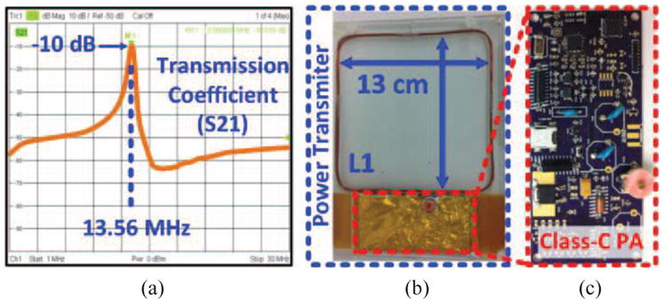
(a) Measured transmission coefficient, S21, in the EnerCage-HC2 prototype between L1 and L4. (b) PA and L1, which are located at the bottom of the homecage (see Fig. 6c). (c) Class-C PA custom PCB.
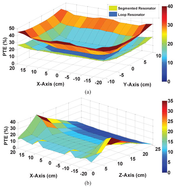
Fig. 8a compares the measured PTE for the EnerCage-HC2 with 2-segment 25 mm-wide copper foil Tx resonators (the upper surface) with that of a similar EnerCage with single- loop magnet wire Tx resonators when the Rx is swept horizontally across XY-plane at the height of d = 7 cm (the lower surface). As expected, due to the large size of the Tx coils with respect to L3 and L4 dimensions, the area at the center of the homecage represents the worst case condition in terms of PTE. Nevertheless, the segmented copper foil resonators have achieved PTE = 14% in this area vs. only 6% for the single-loop magnet wire resonators. As Rx moves closer to the edges of the homecage, the PTE increase significantly, due to the higher coupling between L3 and L21–L24. Fig. 8b shows the PTE measurements when sweeping the Rx across the XZ-plane along the midline of the homecage (Y = 0 cm). The peak PTE is observed at the height of Z = 7 cm, which verifies the proper geometrical design of the EnerCage-HC2 multi-coil Tx in section III, particularly the high-Q segmented resonators.
Fig. 8.
Measured PTE inside the EnerCage-HC2 for (a) 25 mm-wide copper foil segmented-by-two vs. single-loop magnetic wire Tx resonators when the Rx is swept across XY-plane at the height of d = 7 cm. (b) PTE of the segmented Tx resonators when Rx is swept along the XZ-plane (Y = 0 cm), showing the peak PTE achieved at the nominal height of d = 7 cm. Compare with simulation results in Fig. 4.
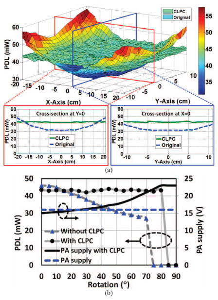
The required average DC power at the output of the rectifier for the 1 channel wireless stimulating headstage, shown in Fig. 2b, is 42 mW, when the stimulator is delivering ~150 μA stimulus pulses at a rate of 100 Hz, and sampling, digitizing, and transmitting Vrec and stimulus current back to the PC-GUI at 100 Hz via BLE1 (see Fig. 2). Fig. 9a shows the measured PDL when the stimulating headstage (Rx) is swept across the XY-plane at a height of d = 7 cm under two operating conditions: 1) Open-loop, i.e. without the CLPC, when Tx power was set at a constant level of 0.47 W. 2) Closed-loop, when Tx power is dynamically adjusted by the CLPC to keep Vref (and PDL) within a user-defined window, as described in section II. The results show the successful operation of the CLPC, which was able to keep the headstage functional up to maximum height of d = 17 cm at the center of the homecage (worst case). The PA supply voltage and transmitted power under this condition were 23 V and 2.16 W, respectively.
Fig. 9.
(a) Measured PDL when Rx is swept across the XY-plane at a height of d = 7 cm without and with CLPC, when Tx power was constant at 0.47 W or varied by the CLPC as needed, respectively. (b) PDL and PA supply voltage as a function of the Rx angular misalignment with and without CLPC.
The CLPC mechanism is also in charge of maintaining the PDL under Rx angular misalignments. To test this, PDL and VPA were monitored in Fig. 9b when the Rx was rotated from θ = 0° to 90° in the center of the homecage at a height of d = 7 cm. Based on our empirical findings with the headstage in Fig. 10b, when Rx receives < 40 mW, the BLE transmission range starts dropping from more than 50 cm to less than 10 cm when the CC2541 supply voltage drops to its minimum level of 2 V. Fig. 9b shows that without CLPC, PDL drops from 45 mW down to 27 mW, which is the minimum level to keep the BLE active up to 70° rotation. However, to keep the BLE distance > 50 cm, which is necessary for reliable reception outside the homecage, the rotation should be limited to 25° only. On the other hand, with CLPC, the Rx receives stable power at 42 mW with up to θ = 80° rotation of the headstage.
B. In vivo Experiments
Fig. 10 shows the in vivo experimental setup, including the EnerCage-HC2 prototype and the 1-ch wireless stimulating headstage. To withstand moisture and mechanical damage, the headstage was covered on both sides with a thick layer of medical grade epoxy, resulting in the overall weight of 5.1 g. Two 16 week old Sprague Dawley rats, weighing 330–350 g were used in this 4-hour pilot study, which was conducted with prior approval from the Institutional Animal Care and Use Committee (IACUC) at Emory University to test the functionality of the EnerCage-HC2 system prototype and the wireless stimulating headstage. Each rat was implanted with a 6 mm electrode in the primary motor cortex to test the effects of stimulation in subsequent trials. The electrode impedances were measured 17 kΩ and 50 kΩ.
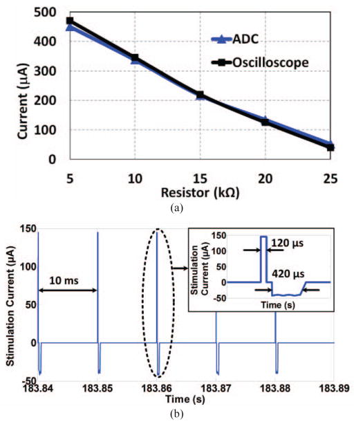
To calibrate the stimulus current sensor in the headstage, a resistor was connected in series with the active electrode and reference ground to emulate tissue/electrode resistance. By changing this resistor from 5 kΩ to 25 kΩ in 5 kΩ steps, the current amplitude in the anodic phase was decoded from the data acquired by the built-in ADC of the headstage MCU and compared with the current measured differentially by an oscilloscope. Fig. 11a shows the result of this calibration, in which the difference is limited to ~20 μA when the emulating resistor is 5 kΩ.
Fig. 11.
(a) Headstage current sensor calibration curve for different electrode-tissue impedances. (b) Measured stimulus current across the 1 kΩ current sensing resistor in Fig. 2b (2 during anodic and 6 during cathodic phases) and transmitted from the headstage via BLE1 link while the animal was freely moving in the homecage.
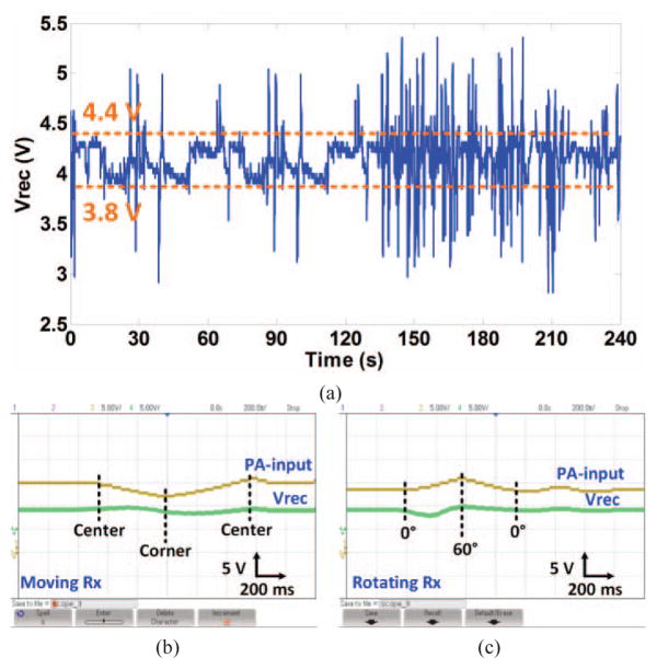
The stimulation frequency and pulse width were set to 100 Hz and 500 μs, respectively, as shown in Fig. 11b. The anodic (active) and cathodic (passive) phases were measured 148 μA and 36 μA, respectively. The ADC, which is activated during stimulation, takes one sample from Vrec and eight consequtive burst of samples from the 1 kΩ current sense resistor (2 samples during anodic phase and 6 samples during the cathodic phase) with 60 μs spacing. These 9 samples are then packetized and sent to the PC-GUI via BLE1 every 10 ms. The electromagnetic field interference on the small loop formed by the driver circuit, stimulating electrodes, and brain tissue is negligible compared to the stimulus current because this loop has small area, low Q-factor due to >10 kΩ electrode impedance, and not being tuned at the carrier frequency. Fig. 12a shows a sample recording of Vrec when the animal was freely behaving inside the homecage and the CLPC was set to keep 3.8 V < Vrec < 4.4 V. As shown in Fig. 12a, as soon as the CLPC algorithm detects Vrec outside the user-defined window, it adjusts VPA and consequently the PA output power by sending control data to the driver block via BLE2 at a rate of 100 Hz.
Fig. 12.
(a) Measured Vrec while the animal was freely moving in the homecage and the CLPC was keeping Vrec within a user-defined window. (b) and (c) Verification of the CLPC functionality by manually moving and rotating the headstage inside the EnerCage-HC2 at a height of d = 7 cm.
The CLPC functionality was also verified by manually moving the headstage from the center of the EnerCage-HC2 to one corner, where the magnetic field is considerably stronger. It can be seen in Fig. 12b that Vrec initially increases from 4.1 V to 4.5 V. However, about the same time VPA starts dropping from 15 V down to 12 V by the CLPC, opposing Vrec variation and returning it back to 4.1 V. When the headstage is moved back to its original position in the center of the homecage, Vrec drops down to 3.8 V but returns back to its original value when VPA returns back to 15 V. The headstage was then manually rotated in place from its horizontal position to θ = 60° and back to θ = 0°, as shown in Fig. 12c. As a result of reduced coupling, Vrec initially drops to 3.8 V, however, it returns back towards 4.5 V and eventually settles at 4.1 V as VPA is adjusted accordingly by the CLPC.
Table II benchmarks key features of the EnerCage-HC2 system vs. previously published work. In comparison to EnerCage-HC1 in [9], from the practical perspective, when one considers all the additional complexities involved with installing, acquiring, and processing the Kinect data, or any other method for real-time animal tracking, to control and switch the coils, we argue that the presented architecture has significant benefits for high throughput and multi-cage applications, offering a more robust and cost-effective solution. Moreover, we have been able to compensate for some of the abovementioned advantages in [9] by utilizing copper foils to further boost the resonators’ Q-factor. One should also consider the improved robustness that results from reduced complexity and removal of the components, such as interconnects, relays, and tracking system that could malfunction.
V. Conclusion
A wirelessly-powered research instrument for conducting physiology and preclinical research on freely behaving small animal subjects has been presented, which is fully compatible with standard homecages used in animal research facilities and CROs. The EnerCage-HC2 system can reliably energize and communicate with a variety of sensors, actuators, stimulators, and drug delivery systems that are attached to or implanted in the animal body wirelessly and indefinitely, while creating an environment close to their natural habitat. Key features of the new EnerCage-HC2 system are: 1) A novel geometrically-optimized array of high-Q segmented resonators, made of copper foils, encompassing the standard homecage to create a homogeneously powered space, while being driven by a single coil and PA located under the homecage; 2) No need for tracking the animal subject for switching the coils, thanks to the self-localizing effect of the transmitted power at the location of the Rx through the strongest coupling formed between the Rx resonator and multiple strategically located and sized Tx resonators; 3) Resonance based wireless power transfer between Tx coil (L1), Tx resonators (L21–L24), Rx resonator (L3), and Rx coil (L4), which provides high PTE and PDL across a large 3D space (20 × 23 × 46 cm3) inside the homecage; 4) A closed-loop power control (CLPC) mechanism established across two BLE links, involving a PC and two MCUs. Several design rules and guidelines have been presented, which can be extended to other homogeneously powered spaces with different shapes and sizes. Several prototypes are implemented and compared with respect to their PTE and PDL within the homecage. Finally in vivo experiments are conducted on two freely behaving rats while successfully activating a simple 1-channel wireless stimulator.
Acknowledgments
This work is supported in part by NSF awards ECCS-1407880 and ECCS-1408318, and NIH award 1R21EB018561.
Biographies
 S. Abdollah Mirbozorgi (S’10–M’16) received the B.S. degree from the Noshirvani University of Technology, Babol, Iran, the M.S. degree from the Ferdowsi University of Mashhad, Mashhad, Iran, and the Ph.D. degree from the Université Laval, Quebec, QC, Canada, all in electrical engineering, in 2008, 2011 and 2015, respectively. Currently, he is a postdoctoral research fellow at the GT-Bionics Lab in the School of Electrical and Computer Engineering, Georgia Institute of Technology, Atlanta, GA. His research interests are neural and bionic implants, wireless implantable biomedical systems, integrated analog circuit design, wireless power/data transmission, and intravascular ultrasound imaging.
 Yaoyao Jia (S’15) received her B.S. degree and M.S. degree in Microelectronics and Solid-State Electronicshina from University of Electronic Science and Technology of China, Sichuan, China, in 2011 and 2014, respectively. She joined GT-Bionics Lab in fall 2014 to pursue her Ph.D. degree in the School of Electrical and Computer Engineering, Georgia Institute of Technology, Atlanta, GA. Her research interests include analog/mixed-signal integrated circuit design, energy harvesting for implantable medical devices, optogenetics, and wireless power/data transmission for biomedical applications.
 Daniel Canales (S’13) will receive his B.S. degree from Georgia Institute of Technology, Atlanta, Georgia, in Spring 2017 in electrical engineering. He has completed a Co-op Program at Georgia Tech and has been part of Opportunity Research Scholars (ORS) Undergraduate Research Program since Fall 2013. Currently, he is a member of GT-Bionics Lab. His interest includes wireless implantable biomedical devices, energy harvesting for medical implants, and wireless power/data transmission. He plans to attend graduate school to further sculpt his career in the design and innovation of implantable medical devices.
 Maysam Ghovanloo (S’00–M’04–SM’10) received the B.S. degree in electrical engineering from the University of Tehran, Tehran, Iran, in 1994, the M.S. degree in biomedical engineering from the Amirkabir University of Technology, Tehran, Iran, in 1997, and the M.S. and Ph.D. degrees in electrical engineering from the University of Michigan, Ann Arbor, in 2003 and 2004, respectively. From 2004 to 2007, he was an Assistant Professor at the Department of Electrical and Computer Engineering, NC-State University, Raleigh, NC. He joined the faculty of Georgia Institute of Technology, Atlanta, GA in 2007 where he is currently an Associate Professor and the Founding Director of the GT-Bionics Lab in the School of Electrical and Computer Engineering. He has authored or coauthored more than 200 peer-reviewed publications.
Dr. Ghovanloo was the general chair of the IEEE Biomedical Circuits and Systems (BioCAS 2015) in Atlanta, GA. He is an Associate Editor of the IEEE Transactions on Biomedical Engineering and IEEE Transactions on Biomedical Circuits and Systems. He served as an Associate Editor of IEEE Transactions on Circuits and Systems, Part II (2008–2011), as well as a Guest Editor for the IEEE Journal of Solid-State Circuits and IEEE Transactions on Neural Systems and Rehabilitation Engineering. He has also served on the Imagers, MEMS, Medical and Displays subcommittee of the International Solid-State Circuits Conference (ISSCC) from 2009–2014. He has received the National Science Foundation CAREER Award, the Tommy Nobis Barrier Breaker Award for Innovation, and Distinguished Young Scholar Award from the Association of Professors and Scholars of Iranian Heritage.
References
- 1.Carbone L. What animals want: expertise and advocacy in laboratory animal welfare policy. Oxford University Press; Oxford, New York: 2004. [Google Scholar]
- 2.Wurbel H. Ideal homes? Housing effects on rodent brain and behaviour. Trends in Neuroscience. 2001;24:207–211. doi: 10.1016/s0166-2236(00)01718-5. [DOI] [PubMed] [Google Scholar]
- 3.Simpson J, Kelly J. The impact of environmental enrichment in laboratory rats-behavioural and neurochemical aspects. Behavioural Brain Research. 2011;222:246–264. doi: 10.1016/j.bbr.2011.04.002. [DOI] [PubMed] [Google Scholar]
- 4.Belayev A, Saul I, Liu Y, Zhao W, Ginsberg M, Valdes M, Busto R, Belayev L. Enriched environments delays the onset of hippocampal damage after global cerebral ischemia in rats. Brain Research. 2003;964:121–127. doi: 10.1016/s0006-8993(02)04089-1. [DOI] [PubMed] [Google Scholar]
- 5.Brauner A, Kurjiaka D, Ibragimov A, Baldwin A. Imapct of cage size and enrichment (tube and shelf) on heart rate variability in rats. Science. 37:2010. [Google Scholar]
- 6.Jow U, Kiani M, Huo X, Ghovanloo M. Towards a smart experimental arena for long-term electrophysiology experiments. IEEE Trans on Biomed Circuits and Systems. 2012;6(5):414–423. doi: 10.1109/TBCAS.2012.2211872. [DOI] [PMC free article] [PubMed] [Google Scholar]
- 7.Jow U, McMenamin P, Kiani M, Manns J, Ghovanloo M. EnerCage: A smart experimental arena with scalable architecture for behavioral experiments. IEEE Trans Biomed Eng. 2014;61(1):139–148. doi: 10.1109/TBME.2013.2278180. [DOI] [PMC free article] [PubMed] [Google Scholar]
- 8.Lee B, Kiani M, Ghovanloo M. A Smart wirelessly powered homecage for long-term high-throughput behavioral experiments. IEEE Sensors Journal. 2015 Sep;15(9):4905–4916. doi: 10.1109/JSEN.2015.2430859. [DOI] [PMC free article] [PubMed] [Google Scholar]
- 9.Millard R, Shepherd K. A fully implantable stimulator for use in small laboratory animals. J Neurosci Methods. 2007 Nov;166(2):168–177. doi: 10.1016/j.jneumeth.2007.07.009. [DOI] [PMC free article] [PubMed] [Google Scholar]
- 10.Cong P, Chaimanonart N, Ko W, Young D. A wireless and batteryless 130mg 300μW 10b implantable blood-pressure-sensing microsystem for real-time genetically engineered mice monitoring. IEEE Intl Solid-State Circuits Conf. 2009 Feb;:428–429. 429a. [Google Scholar]
- 11.Kilinc E, Conus G, Weber C, Kawkabani B, Maloberti F, Dehollain C. A system for wireless power transfer of micro-systems in-vivo implantable in freely moving animals. IEEE Sensors Journal. 2014 Feb;14(2):522–531. [Google Scholar]
- 12.Soltani N, Aliroteh M, Genov R. Cellular inductive powering system for weakly-linked resonant rodent implants. IEEE Biomedical Circuits and Systems Conference (BioCAS) 2013:350–353. [Google Scholar]
- 13.Ho J, Tanabe Y, Iyer S, Christensen A, Grosenick L, Deisseroth K, Delp S, Poon A. Self-tracking energy transfer for neural stimulation in untethered mice. Physical Review Applied. 2015;4(2):024001. [Google Scholar]
- 14.Meng M, Ibrahim A, Kiani M. Design considerations for ultrasonic power transmission to millimeter-sized implantable microelectronics devices. IEEE Biomedical Circuits and Systems Conference (BioCAS); Atlanta, GA. 2015. pp. 1–4. [DOI] [PubMed] [Google Scholar]
- 15.Shmilovitz D, Ozeri S, Wang CC, Spivak B. Noninvasive Control of the Power Transferred to an Implanted Device by an Ultrasonic Transcutaneous Energy Transfer Link. IEEE Transactions on Biomedical Engineering. 2014 Apr;61(4):995–1004. doi: 10.1109/TBME.2013.2280460. [DOI] [PubMed] [Google Scholar]
- 16.Harrison R. Designing efficient inductive power links for implantable devices. Circuits and Systems, ISCAS2007, IEEE International Symposium on. 2007 May;:2080–2083. [Google Scholar]
- 17.Schuylenbergh KV, Puers R. Inductive powering basic theory and application to biomedical systems. Analog Circuits and Signal Processing, Springer; 2009. [Google Scholar]
- 18.Tehrani AH. PhD dissertation. Technischen Universität Darmstadt; Darmstadt, Germany: 2015. Design and optimization of printed antennas for wireless powering. [Google Scholar]
- 19.Kiani M, Jow U-M, Ghovanloo M. Design and optimization of a 3-coil inductive link for efficient wireless power transmission. IEEE Transactions on in Biomedical Circuits and Systems. 2011 Dec;5(6):579–591. doi: 10.1109/TBCAS.2011.2158431. [DOI] [PMC free article] [PubMed] [Google Scholar]
- 20.Eom K, Jeong J, Lee TH, Kim J, Kim J, Lee SE, Kim SJ. A wireless power transmission system for implantable devices in freely moving rodents. Medical & Biological Engineering & Computing, Springer. 2014 Aug;52(8):639–651. doi: 10.1007/s11517-014-1169-3. [DOI] [PubMed] [Google Scholar]
- 21.Kiani M, Ghovanloo M. The circuit theory behind coupled-mode magnetic resonance-based wireless power transmission. IEEE Transactions on Circuits and Systems I: Regular Papers. 2012 Sep;59(9):2065–2074. doi: 10.1109/TCSI.2011.2180446. [DOI] [PMC free article] [PubMed] [Google Scholar]
- 22.Vaughan JT, Griffiths JR. RF Coils for MRI. Wiley; Nov, 2012. [Google Scholar]
- 23.Yang P, Li Y, Jiang L, Yang F. Near-field loop antenna for the UHF RFID reader. Journal of Electronic Science and Technology. 2011 Sep;9(3) [Google Scholar]
- 24.Tang S, McDannold N. Power loss analysis and comparison of segmented and unsegmented energy coupling coils for wireless energy transfer. IEEE Journal of Emerging and Selected Topics in Power Electronics. 2015 Mar;3(1) doi: 10.1109/JESTPE.2014.2330951. [DOI] [PMC free article] [PubMed] [Google Scholar]
- 25.Mark Michael. PhD Thesis. University of California; Berkeley: 2012. Powering mm-Size Wireless Implants for Brain-Machine Interfaces. [Google Scholar]
- 26.Cole P, Ranasinghe D, Jamali B. Coupling relations in RFID systems II: Practical performance measurements. Auto-ID Centre, University of Adelaide; Adelaide, SA, Australia: 2004. [Google Scholar]
- 27.rfcafe.com. Dielectric Constant, Strength, & Loss Tangent. 2016 Available: http://www.rfcafe.com/references/electrical/dielectric-constants-strengths.htm.
- 28.Lenarets B, Puers R. Analog circuits and signal processing. Springer; New York, USA: 2009. Omnidirectional inductive powering for biomedical implants. [Google Scholar]
- 29.Finkenzeller K. RFID Handbook: Fundamentals and applications in contactless smart cards and identification. 2. West Sussex: Wiley, England; 2003. [Google Scholar]
- 30.Sharma A, Garcia Zuazola I, Batchelor J, Perallos A. Dual purpose near- and far-field uhf rfid coil antenna with non-uniformly distributed-turns. IEEE Antennas and Wireless Propagation Letters. 2015;14:1342–1345. [Google Scholar]
- 31.Mirbozorgi SA, Bahrami H, Sawan M, Gosselin B. A Smart cage with uniform wireless power distribution in 3D for enabling long-term experiments with freely moving animals. IEEE Transactions on Biomedical Circuits and Systems. 2016 Apr;10(2):424–434. doi: 10.1109/TBCAS.2015.2414276. [DOI] [PubMed] [Google Scholar]
- 32.trianglebiosystems.com. Inductive Power Accessory. 2015 Available: http://www.trianglebiosystems.com/inductive-power.html.
- 33.Gabriel S, Lau RW, Gabriel C. The dielectric properties of biological tissues: II. Measurements in the frequency range of 10 Hz to 20 GHz. Phys Med Biol. 1996;41:2251–2269. doi: 10.1088/0031-9155/41/11/002. [DOI] [PubMed] [Google Scholar]
- 34.IEEE Standard for Safety Levels With Respect to Human Exposure to Radio Frequency Electromagnetic Fields, 3 kHz to 300 GHz, IEEE Std. C95.1, p. 1, 2005.


