Abstract
Object
Prospective motion correction (PMC) during brain imaging using camera-based tracking of a skin-attached marker may suffer from problems including loss of marker visibility due to the coil and false correction due to non-rigid-body facial motion, such as frowning or squinting. A modified PMC system is introduced to mitigate these problems and increase the robustness of motion correction.
Materials and Methods
The method relies on simultaneously tracking two markers, each providing six degrees of freedom, that are placed on the forehead. This allows us to track head motion when one marker is obscured, and detect skin movements to prevent false corrections. Experiments were performed to compare the performance of the two-marker motion correction technique to the previous single-marker approach.
Results
Experiments validate the theory developed for adaptive marker tracking and skin movement detection, and demonstrate improved image quality during obstruction of the line-of-sight of one marker, when subjects squint, or when subjects squint and move simultaneously.
Conclusion
The proposed methods eliminate two common failure modes of PMC and substantially improve the robustness of PMC and can be applied to other optical tracking systems capable of tracking multiple markers. The methods presented can be adapted to the use of more than two markers.
Introduction
Motion is a well recognized problem in any medical imaging modality. For MR imaging (MRI), subject motion during a scan can result in the need to repeat scans, and ultimately in extended scan times and thus increased costs for both clinical and research applications. Extended scan time can also lead to more discomfort for the subjects/patients depending on their demographics. Methods for motion correction in MRI can broadly be classified into retrospective and prospective correction techniques, with each approach having its own merits [1-3].
Prospective motion correction (PMC) for MRI using external tracking systems has proven effective in mitigating the effects of subject motion for a variety of MRI modalities without increasing the scanning time [3-9]. Several external motion tracking systems used for MR are optical in nature, consisting of a camera (or cameras) and one or more markers attached to the surface of the object to be imaged (e.g., the head for brain MRI). The motion of the marker is estimated from camera images, and prospective updates of the MRI sequence are performed in real-time by adjusting the position and orientation of the imaging volume during the scan, such that the slices remain aligned to the (moving) marker for the entire acquisition duration. The benefits of camera-based tracking systems include high frame rates and independent operation from the MRI scanning process. Optical tracking based motion correction systems are effective in cooperative volunteers [10,7,11], but can fail to achieve adequate motion correction in uncooperative subjects.
The efficacy of PMC relies on at least two assumptions: 1) the marker is visible to the camera continuously throughout image acquisition, and 2) the imaged object together with the attached marker forms a rigid-body. All optical tracking systems require a continuous line of sight from the camera to the marker. Visibility depends on the position of the camera and marker with respect to the receive coil, the shape of the coil and the magnitude of motion. For most configurations, sufficiently large head movements will result in the marker(s) being obscured by the coil; any motion that occurs while the marker is obstructed is not corrected for, and will result in residual artifacts in the final image. Additionally, marker-based tracking systems presume that the marker moves rigidly with respect to the tissue of interest. Although certain non-rigid motions may occur inside the brain (e.g., CSF/blood flow), non-rigid (marker) movements may also occur due to motion of the skin relative to the skull. For instance, if a marker is placed on the forehead, a change in facial expression, such as moving the eyebrows or squinting, can result in marker motion even if the head remains stationary. Corrections based on such false marker motions may cause motion-like artifacts even in the absence of head motion [10] .
In this paper, we investigate the effects of marker obstruction and skin movement on brain MRI and propose the use of two or more markers placed on the subject’s forehead to address these issues. The purpose of attaching two markers is to obtain redundant data that help us in making intelligent decisions for feedback and determining the nature of the motion. We demonstrate the use of a second marker to achieve continued tracking of head motion even when one marker is obscured by the coil (“adaptive tracking”). Also, when both markers are visible, the relative position of the two markers can be monitored and used to detect the presence of non rigid-body motion. Once non rigid-body motion is detected, the scan data for that k-space line are rejected and the data are reacquired once the condition is removed. Together, these two measures reduce two common failure modes of PMC and thus create a more robust PMC system. It is theoretically straightforward to extend the proposed approach beyond optical tracking systems and apply the same principles to any motion tracking modality capable of providing pose information from multiple markers simultaneously.
Theory
Marker Switching (Adaptive tracking)
When tracking a single marker, larger head movements may result in the marker going out of FOV of the camera, or lead to partial or complete obstruction in marker visibility due to opaque structure of the head RF coil. However, if two markers are placed on the subject, then one marker may remain visible when the second one is obstructed. Assume that the reference marker initially used for PMC is marker 1, and that the homogeneous transform between the two markers is known (from a period when both markers were visible). Presuming rigid-body motion and using the relative transform between the two markers, the pose of marker 2 can then be used to determine the location of maker 1, even when marker 1 not visible. This can also be proved for n markers (n ≥ 2), as shown below.
Marker pose can be described by a 4 × 4 homogeneous matrix (M) that comprises a 3 × 3 rotation matrix and translation vector (d)
| (1) |
Let M(t0) be the initial pose of the rigid-body. After undergoing motion A(t), the new pose M(t) at time t can be determined from M(t0) by
| (2) |
Consider the situation where there are n markers on one rigid-body. In analogy to Eq.(2), we obtain for marker i:
| (3) |
or
| (4) |
Under the constraints of rigid-body motion, the change in pose for any two markers must be identical, i.e. Ai(t) = Aj(t). Consequently,
| (5) |
| (6) |
Rewriting Eq. (5) yields:
| (7) |
Therefore, if two markers are visible at some time point (t0), i.e. Mj(t0) and Mi(t0) are known, then the pose Mi(t) can be calculated from Mj(t) at any time point (and vice versa). This ultimately allows for continuous updates of the imaging volume in the MR pulse sequence even if one of the two markers is obstructed.
Skin movement (Squint) detection
As noted, PMC operates under the assumption that the imaging object is undergoing rigid-body motion. However, if the marker attachment point on the skin moves relative to the brain, for instance due to squinting, then the rigid-body assumption is violated. In this case marker movement will not reflect movement of the tissue to be imaged. This results in false adjustments to the scan parameters, and may introduce artifacts in the image. To mitigate this effect, we propose using the relative pose ΔMij(t) between two markers i and j to detect non rigid-body motion events. Using the relative marker position as an indicator of skin motion is based on the hypothesis, that marker motion due to the skin mobility at different locations on the head is very unlikely to be the same. Starting with equation (6), we calculate:
| (8) |
For rigid-body motion, ΔMij(t) = I, where I is the identity matrix. In general terms, “squinting” at a time ts alters the relative transform between the two markers, such that:
| (9) |
For simplicity, our experiments were performed with n=2 markers.
Figure 1a shows the relative rotation from a consented clinical in-patient (adult) on whom motion tracking was performed using two markers. The clinical scan was performed in a Siemens Verio 3T scanner with a 12 channel coil. Figure 1b shows the calculated relative rotation from a teenager undergoing a research protocol in a Siemens Trio 3T scanner with a 12 channel coil. The marker positions were similar to Fig.3 (left). The data in Fig.1 are intended to show the type of tracking effects pertaining to skin movement that can occur during involuntary motion. The relative rotation for most skin movements looks similar to Fig.1b (inset) but the duration may be shorter or longer.
Fig. 1.
a) Relative rotation values for a clinical patient undergoing the standard protocol (No PMC enabled scans were performed). More activity can be seen after the injection of contrast agent. b) Relative rotation values for a research subject who was instructed to hold still during the scan, but showed involuntary motion. Inset shows a zoomed course of a squint.
Fig. 3.
Illustration of motion trajectory during experiment 2 (Adaptive marker tracking). Initial placement is such that both markers are visible (left). A head rotation can obscure M1 (center) or M2 (right). Extremely large motions could also cause both markers to move out of the camera’s FOV
Materials and Methods
Experiments were performed on a 3T Tim Trio system, using a 12 channel head coil (Siemens Healthcare, Erlangen, Germany) and a prototype in-bore optical tracking system (Moiré Phase Tracking, or MPT, Metria Innovation Inc., Milwaukee, WI). The tracking system features errors of less than 0.1 mm RMS for position measurements and 0.1 degree RMS for orientation measurements within the angular range of 120 × 120 × 360 degrees (Metria Innovation Inc., Milwaukee, WI, vendor specification). The optical tracking system used for the current work has the additional advantage of obtaining positional information (six degrees of freedom) from a relatively small (15 mm × 15 mm) marker, using a single camera, and can track up to 3 markers simultaneously with one camera. The tracking system by Metria Inc. uses an 8-bit self identification barcode imprinted on each marker. The marker ID number is read from each marker in each frame which is then transmitted through the User Datagram Protocol (UDP) packet structure.
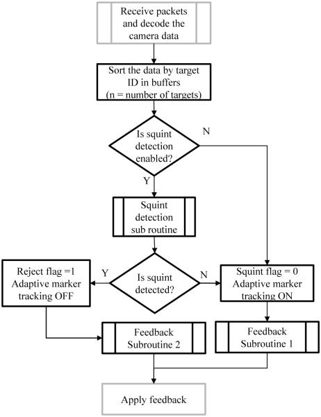
The tracking system was operating at 60 frames/second, with each marker being exclusively tracked by one tracking process allocated to a specific CPU core. PMC was integrated into both MP-RAGE [12] and gradient echo (GRE) sequences. The communication interface between the sequence and the camera was provided by the XPACE library [5]. An additional multi-marker module was developed, allowing the XPACE library to process data from multiple markers without affecting other functionality. The additional module consists of a feedback/switch detector routine and a squint detector routine (Fig.2). The output of the squint detector routine was used to discard and reacquire raw data [5]. To ensure that the algorithm does not keep rejecting data continuously and thereby extend the scan indefinitely, a user-defined maximum number of rejects was set. A log file was written to record the ID of the markers used for each prospective correction. The module was programmed to apply marker 1 as the feedback by default. Experiments were performed with and without the multi-marker processing module. For obtaining the homogeneous transform between the markers, care was taken to ensure that tracking data for the two markers originated from the same optical frame number (i.e. same hardware time stamp). Averaging was not used during the initialization of the homogeneous transform between the markers since the precision of a single reading was sufficient for the experimental conditions and the chosen squint detection threshold. Note that values of total rotation and relative rotation reported in this paper refer to their absolute values.
Fig. 2.
Flowchart showing a high level representation of the processing algorithm for the data from two markers. Gray outlines indicate pre- existing XPACE subroutines; black outlines represent new subroutines
Four experiments were performed. Experiment 1 was performed to evaluate multi-marker tracking accuracy using a phantom. Three in-vivo experiments were performed (experiments 2, 3, and 4), each with four volunteers to evaluate the efficacy of the multi-marker processing module. Verbal and written consent was obtained, using a study protocol approved by our local Institutional Review Board. Experiment 2 was performed to evaluate the ability to switch between markers for tracking using MP-RAGE, and experiment 3 was performed to test the skin movement/squint detection algorithm using GRE. Experiments 2 and 3 were performed on the same set of 4 volunteers. Experiment 4 was performed with 4 different healthy volunteers to test the module for complex motion involving simultaneous rigid and non rigid-body motion. The obtained images from experiment 4 were rated for the severity of the motion artifacts by two independent physicians who were blinded to the motion-correction protocol employed.
Experiment 1: Multi-marker tracking accuracy
Although both markers can be tracked at the specified system accuracy, parameters describing their relative motion need to be measured in order to calculate expected tolerances. An experiment was performed to evaluate a relevant relative motion parameter that could be used to detect non-rigid body motion. In the experiment, we compared the absolute value of the total rotation angle of ΔM12 to the L2 norm of translations from ΔM12. A small initial study was also performed to determine an appropriate threshold value for detecting a squint event. Tracking data were acquired from 2 markers mounted on a rigid phantom to ensure rigid-body motion. The phantom was mounted on one end of a long wooden plank that was used as a lever to move the phantom. Tracking data was first obtained without phantom movement. Next, the phantom was moved manually to mimic a nodding motion (x-rotation + z-translation) with arbitrary amplitude and velocity while being tracked by the optical system. The calculated values for ΔM12 were then used to estimate the errors in the tracking data.
Experiment 2: Adaptive marker tracking
Two markers were placed on the subject's forehead such that both markers were initially visible to the camera to initialize the relative marker position (based on M1(t0) and M2(t0)). The subject was instructed to perform a large-amplitude periodic left-to-right head movement during the scan, such that each marker was obstructed by the RF coil at some time periods during the scan (X translation: ~55 mm peak to peak, Z rotation: ~31 degrees peak to peak). This controlled motion was guided by the scanner operator. An illustration of the motion is shown in Fig.3. The MP-RAGE scan parameters were TR/TI/TE = 2200/1100/4.15 ms, flip angle = 9°, phase and slice partial Fourier 6/8 and 7/8, FOV = 256 × 232 × 176 mm3, 1mm isotropic resolution, iPAT = 2 and total acquisition time 3 minutes and 37 seconds. The scan was done twice with similar motions, once with adaptive tracking enabled and once with adaptive tracking disabled (i.e. tracking one marker only). Squint detection and reacquisition was disabled for both scans.
Experiment 3: Skin movement detection
For the in vivo experiment, the subjects were asked to keep the head motionless and squint at regular intervals (every 20 s) as guided by the scanner operator. The scan parameters for the GRE sequence were TR/TE = 505/20 ms, flip angle = 25°, voxel size = 1.1 × 1.1 × 3.0 mm3 and total acquisition time 99 seconds. During scanning, motion was labeled a "squint" when the relative marker rotation angle (Eq. (9)) exceeded the threshold of 1°. When a squint was detected, the data from the current k-space line were discarded and reacquired. Thus, every squint-type motion extended the scan time by one TR period. The experiment was performed twice with PMC enabled, once with squint correction disabled and once with squint correction enabled. In both cases, the number of squints was the same and the same marker was used as the reference marker (the default marker used for feedback).
Experiment 4: Rigid body motion and skin movement
This experiment was performed on four healthy volunteers (different from those in experiments 2 and 3) who were asked to flex (nod) their head downward once while squinting, stop the squinting and extend (pull) the head back up. Since the motion was sophisticated, the volunteers were asked to perform a small nod with any type of squint that they performed. This controlled motion was triggered by the scanner operator. The MP-RAGE scan parameters were TR/TI/TE=2200/1100/4.15 ms, flip angle = 9°, FOV = 256 ×232×176 mm3, 1mm isotropic resolution, iPAT = Off, partial Fourier 6/8 and 7/8 (phase and slice), and total acquisition time 6 minutes and 25 seconds. The experiment was performed twice with PMC enabled, once with squint correction disabled and once with it enabled. In both cases, the number of guided squints was the same. The labeling and reacquisition process was similar to experiment 2.
Results
Experiment 1: Multi-marker tracking accuracy
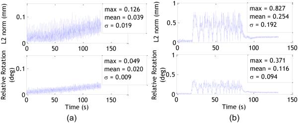
Table 1 lists motion parameters for each marker recorded during experiment 1. The center to center distance between the markers was measured to be 24.67 mm and the relative angle was measured as 167.5°. The values in the table have been calculated with respect to a reference pose for each marker, which is how XPACE provides a feedback. While table I shows the individual motion of the markers, Fig.4 shows the relative motion between the markers as calculated from ΔM12. The camera measurement with maximum errors is the z-axis in the camera frame (depth). As such, we can assume total rotation angle to be a more reliable indicator for relative marker movement. Figure 4a shows the relative motion parameters for the markers when the phantom is stationary. Tracking data obtained from a stationary phantom are indicative of random errors. The small drift visible in the plot (<0.05° over 5 minutes) could be a result of camera measurement drift due to increase in sensor temperature or stabilization of foam padding on which the phantom was placed. Even though it is difficult to directly compare translations and rotations, from Fig. 4a, it can be observed that the standard deviation for relative distance is higher than that of the rotation. This trend is reflected in the Fig. 4b, which shows the plots for simulated nodding of the phantom. Tracking data from a moving phantom include systematic errors and are at least an order of magnitude higher than the random errors. In both cases, the standard deviation for relative distance is a little more than twice of the standard deviation for relative rotation. The mean absolute rotational speed during nodding was 0.98°/s. Using 4σ as the threshold, we can calculate the minimum threshold for relative rotation (mean + 4σ) to avoid false positives as 0.49°. The sensitivity of the system can be adjusted by choosing a value above 0.49° with higher values making the system less sensitive to skin motion. For our experiments, we chose a threshold of 1° to exclude random alarms due to tracking errors.
Table I.
Maximum Rotation and translation (L2 norm) for individual markers for 'no movement' and simulated nodding condition.
| Relative distance (mm) |
Relative Angle (deg) |
Marker No. |
No Motion | Nodding | ||
|---|---|---|---|---|---|---|
| Max rotation (deg) |
Max Translation (L2 norm, mm) |
Max rotation (deg) |
Max Translation (L2 norm, mm) |
|||
| 24.67 | 167.5 | 1 | 0.02 | 0.07 | 5.97 | 5.79 |
| 2 | 0.04 | 0.11 | 5.81 | 5.51 | ||
Fig. 4.
L2 norm of translations (top) and relative rotation (bottom) between the two markers (ΔM12) when the phantom was stationary (a) and with nodding motion (b). The total measurement duration for both cases was approximately 132 seconds. The absolute mean and maximum relative rotations between the markers was 0.02° and 0.05° for the “no movement” condition, and 0.12° and 0.37° for simulated nodding
The degree of skin movement varies from person to person and the perceived relative rotation would also depend on the relative position of the markers. To provide a statistical analysis for the occurrence of squints would require a larger study of clinical patients which is beyond the scope of this paper. Relative translation or Euclidean distance between the markers may also be used in the future to calculate the threshold to adjust for the dependency of relative rotation on the placement of two markers.
Experiment 2: Adaptive marker tracking
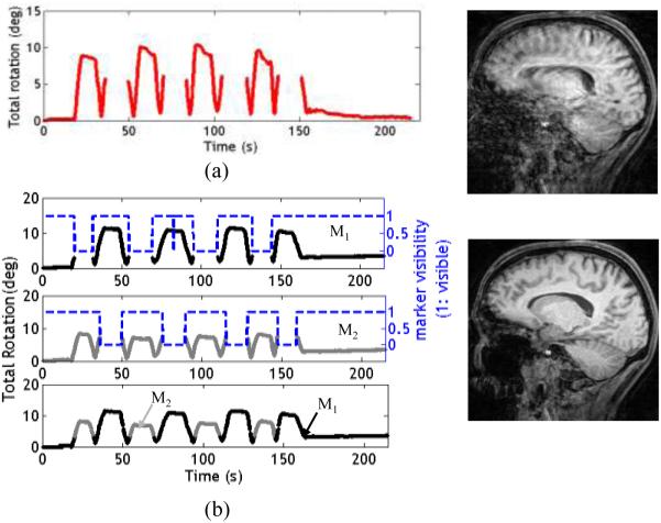
Figure 5a shows the plot of total rotation when a subject with one marker performed a large head movement. This motion leads to loss of continuity in tracking data (seen as gaps in Fig.5a). The resulting image shows severe residual motion artifacts, since motion correction was incomplete. Figure 5b displays the results from adaptive marker tracking for a similar motion. Visibility of marker 1 is displayed using dashed blue lines. In the absence of marker 1, feedback switched to marker 2 (Fig. 5b, bottom plot, gray line). The resulting image displays clearly reduced motion artifacts.
Fig. 5.
Results from experiment 2. a) Subject had one marker placed on his forehead. Periods when the marker was obscured by coil elements have no camera data and hence no feedback; the corresponding image contains artifacts (5a, right). b) Plots showing total rotation, marker visibility and the feedback applied for both markers. A visibility value of 1 indicates that marker 1 was visible. Instances when the markers are not visible can be seen as gaps in the data. If marker 1 becomes obscured, the algorithm uses marker 2 (if visible) to compute the location of marker 1 and provide feedback. The motion artifacts in the resulting image are clearly reduced (5b, right)
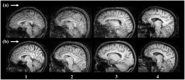
Figure 6 compares images obtained from one marker tracking (Fig. 6, row a) and from adaptive tracking (Fig. 6, row b) for all four subjects. The maximum peak to peak total rotation angle was around 20 degrees and the rotational speed (total rotation) ranged from 3-8 deg/s. The motion performed by each subject was similar but not reproducible. The scans in row b have more clarity and reduced artifacts due to complete motion correction. The variation in the image quality for both experimental conditions may result from the varying skin movement (squinting) that was not corrected for. Table II shows the mean and maximum relative rotation for subjects during adaptive marker tracking when both markers were visible. Table II indicates that subjects 2 and 4 had a few time frames (< 3 seconds) during which their motion would have been detected as a squint.
Fig. 6.
Comparison of image slices obtained from experiment 2 for all subjects. Row (a) shows images from motion correction with one marker, and row (b) shows motion correction with two markers. Images in row (b) show significant improvement over images in row (a)
Table II.
Mean and maximum relative rotation values for subjects with two markers during experiment 2.
| Subject | Relative Rotation (deg) |
Total frames with relative rotation>1° |
Total Frames where both markers are visible |
Total Frames | |
|---|---|---|---|---|---|
| mean | max | ||||
| 1 | 0.36 | 0.70 | 0 | 7641 | 13015 |
| 2 | 0.30 | 2.97 | 137 | 7853 | 13015 |
| 3 | 0.37 | 0.63 | 0 | 6402 | 13015 |
| 4 | 0.34 | 1.22 | 14 | 8025 | 13015 |
Experiment 3: skin movement detection
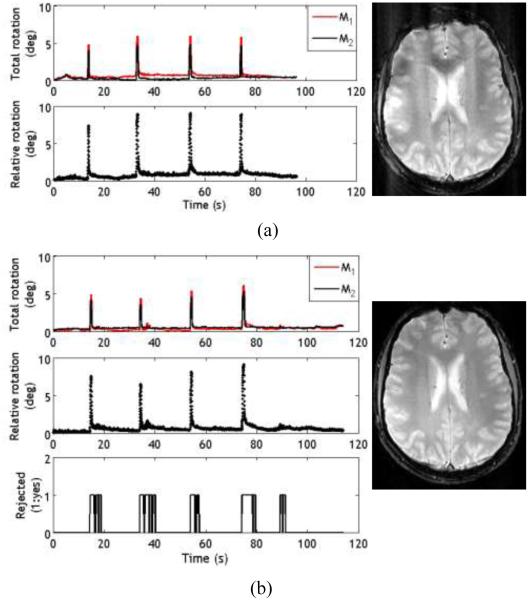
Figure 7a shows the motion trajectory with squint detection and reacquisition disabled. Artifacts caused by squinting can be seen in the corresponding image (7a, right). Although the number of squints (4) are small and their total duration (<10 s) is only a fraction of the total scan time, their effect on the image is noticeable. Figure 7b shows the results with squint detection and reacquisition enabled. The reject mode (bottom plot) is activated as soon as a squint is detected. The resulting image (7b, right) is clear and does not show artifacts like those in Fig.7a, right. The magnitude of relative rotation during squints was between 5°and 10° for both cases.
Fig. 7.
Results from experiment 3 with the subject squinting at regular intervals during the scan. a) Plots from the case when the squint detection and reacquisition was disabled. The calculated total rotation and relative rotation are shown. The corresponding image (7a, right) shows the presence of artifacts due to false correction. b) Plots from the scan where squint detection and reacquisition was enabled. A value of 1 in the bottom graph indicates that the scan data was rejected and reacquired (as evident by the increased scan time), resulting in a clear image with significantly less artifacts (7b, right)
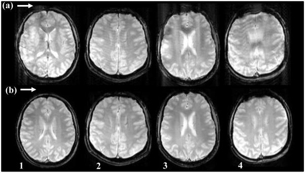
Table III shows that the maximum relative rotation across our subjects varied between 2.3° and 9.1°, although the subjects were asked to perform the same general motion. The variation in marker positions was not too large due to similar camera position and marker placement for all subjects. The relative rotation values for squint correction OFF and ON are consistent for each subject, indicating uniformity of the skin movement performed by the subject. Some residual artifacts may still be present in the images due to skin movement that was below 1°. Figure 8 compares images obtained without squint detection and reacquisition (Fig. 8, row a) and with squint detection and reacquisition (Fig. 8, row b) for all four subjects. Reacquisition of data results in reduced artifacts and clear images as shown in Fig.8, row b.
Table III.
Mean and maximum relative rotation values for subjects with two markers during experiment 3 with squint correction OFF and ON
| Subjects | Mean Relative Rotation (deg) |
Max Relative rotation (deg) |
||
|---|---|---|---|---|
| Two marker |
OFF | ON | OFF | ON |
| 1 | 1.29 | 1.10 | 8.24 | 7.82 |
| 2 | 1.82 | 1.29 | 6.98 | 7.20 |
| 3 | 0.86 | 0.67 | 9.09 | 9.10 |
| 4 | 0.59 | 0.55 | 2.98 | 2.38 |
Fig. 8.
Comparison of axial images from experiment 3 for all four subjects. Row (a) shows images obtained with motion correction enabled but with squint correction disabled, and row (b) shows images with both motion correction and squint correction enabled. Images in row (b) show reduced artifacts compared to corresponding images in row (a)
Experiment 4: Rigid body motion and skin movement
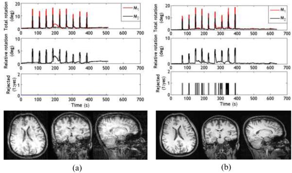
Figure 9a shows the results with squint detection and reacquisition off. In addition to the guided squints that can be seen as sharp peaks in the traces, some additional squints are visible throughout the scan. Additional motion is expected owing to the long scan time, although the nature of such motion is unpredictable. If the squint correction is disabled, then false corrections are applied, resulting in artifacts as seen in Fig. 9a. Additional squints (relative rotation >1°) can also be seen in Fig. 9b, when the squint detection and reacquisition module are on. However, with squint correction on, when a reject signal is detected, the entire echo train of MP-RAGE acquisition is rejected and reacquired, resulting in improved images (Fig.9b).
Fig. 9.
Results from experiment 4. a) Plots from the case when the squint detection was disabled. The total and relative rotations are shown in the top and the corresponding images below show some artifacts. b) The data obtained during instances of squint are rejected and reacquired (top) resulting in improved images
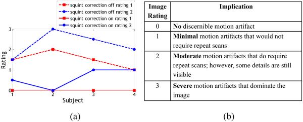
Figure 10a shows the absolute rating of the images by both physicians. And Fig. 10b shows the scale for scoring that was provided to the physicians. Both physicians rated images obtained with the multi-marker module to have less pronounced artifacts compared to those obtained using single marker tracking. The average improvement with squint rejection and reacquisition across all scans was 1.5 for rater 1 and 1.6 for rater 2. Importantly, images acquired with squint correction were almost always of better quality, and never worse, than those without correction. The Intraclass Correlation Coefficient (ICC) between the two readers for type ‘Consistency’ (systematic differences between readers are irrelevant) was calculated to be 0.94, indicating excellent agreement between the readers.
Fig. 10.
a) Rating given by both physicians to the images obtained from experiment 4. b) Rating scale for images. Increments of 0.5 were allowed. For subject 4, the absolute rating given by rater 1 for the uncorrected case and rater 2 for corrected case are identical. The calculated intra class correlation was 0.94 (average measures)
Discussion
We demonstrate a PMC method that is capable of utilizing tracking data from two markers placed on the object to be imaged. The method allows us to 1) solve the problem of marker obstruction caused by large subject motion and 2) detect non rigid-body motion (skin motion) when both markers are visible. These are two problems that have obtained little attention in the literature to date, but will need to be resolved for clinical application of PMC with optical tracking. The placement of two markers is not limited to the configuration shown in our experiments and may vary with the shape of head coil, camera placement and use of additional hardware (for example, goggles for functional MRI).
Although the images from our experiments with modified PMC show clearly reduced artifacts, it would be useful to have an objective measure for quantifying motion artifacts. Since it is difficult to replicate the motion performed by a human subject, a significant level of sophistication would be required to objectively compare the resulting images. A very recent study by Pannetier et al [13] has proposed one such framework and used it to compare the performance of two marker fixation methods.
Another approach to solve the problem of marker visibility is the use of a larger “self-encoded” checkerboard marker [11,14]. The range of motion that can be tracked with this system is limited only by the size of the marker and not by the FOV of the camera. Although similar in nature to our approach, adaptive marker tracking using two markers may be advantageous with respect to subject comfort, and the extra information about skin movement that it provides. Of note, the theory presented for the detection of skin movement (Eq. 9) can be applied to other marker solutions, including the self-encoded markers, as well, provided one can affix and track two or more markers.
Marker visibility is not a problem for tracking systems based on NMR probes [15] or systems with active markers [16]. However, these systems typically require tracking of three markers that are attached to the skin (forehead) or a rigid frame, and projections from all three markers are combined to calculate the pose information in six degrees of freedom. One might be able to detect skin motion by placing additional (e.g. 6) markers on the skin, but due to the small available working area, the placement of a larger number of independent markers may be limited.
As noted in the theory section, the concept of adaptive marker tracking can easily be extended to more than 2 markers. Use of a single frame to calculate the initial homogenous transform between the two markers rests on the assumption that the subject is not squinting at this particular moment. To ensure that this assumption is true, future implementations may use motion information from individual markers to determine that both markers are stationary before calculating the homogeneous transforms between the markers. The range of motion performed during experiment 1 (adaptive marker tracking) was fairly large and seems to cover the expected range of motion for most clinical cases, especially as patients are instructed to not move in regular clinical scans.
Large motions are expected to cause changes in sensitivity maps, and B0 susceptibility. These effects and potential issues have been discussed in Maclaren et al [3] . However, in our studies, we have not yet observed artifacts caused by B1 sensitivity profiles with a 12-channel coil. In another study, simulations for 12 and 32 channel coils revealed no sensitivity changes for rotations of up to 5 degrees [17]. A maximum difference of 160 Hz in the field maps for a 12° nodding type motion was shown in Maclaren et al [3].
Marker motion due to skin mobility is expected to be dependent on the exact location on the face, so multiple markers at different locations will show different motions in response to a facial expression. For the same reason, during experiment 2, it was ensured that the same default marker was used for feedback in both cases. Although the use of only the rotational information to set the threshold for squint detection seems sufficient, the translational information from ΔM (8) could also be used to understand the nature of skin movement in more detail. Also, it may be possible to further improve detection of squints by using relative velocities instead of the absolute changes in relative pose [18]. Selection of threshold is a compromise between limiting false positives (lower bound) and achieving sufficient sensitivity to detect skin motion (upper bound). The false positive rate is driven by the noise properties of the tracking system. The criterion for sensitivity is that sub-threshold skin motion does not result in significant image artifacts, and may be determined using simulations by injecting false tracking data at the center of the k-space (for various pulse sequences of interest). As long as the threshold for an acceptable false positive rate is lower than that for acceptable image artifacts, then any value between the two bounds may be chosen, although the best value may be closer to the lower bound (to optimize image quality). We believe that this situation applied to our studies and the threshold of 1 degree relative rotation did not cause significant deterioration in image quality in the test scans performed. .
The premise for rejecting and reacquiring data comes from the fact that we are performing PMC with online reconstruction, implying that any skin movement will result in false corrections (corrupt k-space data) since the brain has not moved. Alternative strategies could be applied if we were to use some form of combined PMC and retrospective motion correction. The practical number of rejects could be a percentage of total scan time deemed reasonable to extend and would vary by subject demographics. Our present approach is not able to quantify the skin motion occurring in each marker using ΔM (8). In theory, separation of pose information into rigid body and non rigid body motion would allow us to perform selective correction without the need for data rejection.
External tracking systems have also been proposed for real time motion tracking in other imaging modalities, such as PET, to overcome the limitations of software based motion compensation techniques [19-23] . Due to the advent of simultaneous MR/PET devices, techniques involving the use of MR images for motion correction of PET images have also been introduced [24,25]. Although implementation and results are shown for PMC enabled MRI, the algorithms presented for detection of squints for marker based tracking systems could provide valuable information for retrospective motion correction techniques of PET images as well.
Our approach addresses two important potential failure modes of PMC. However, there is another possible failure mode for both single marker or multi-marker tracking, where the marker shifts from its position by a small amount (‘marker slippage’), perhaps after the subject undergoes motion (rigid-body or most likely skin motion), after a substantial squinting event or due to a slow gradual change in the adhesion of the marker to the skin. However, one should be able to minimize these issues by optimizing the attachment of the markers to the skin, e.g. carefully cleaning the marker and the skin before affixing the marker and using a glue that is insensitive to skin moisture and skin oil.
Conclusion
We have shown that redundant data from a second marker could be effectively utilized to create a robust PMC system that can alleviate problems caused by loss of visual contact with one marker, and detect skin movements to prevent false corrections. Although the current methods have been developed for the MPT system, they can be applied to any optical system that allows simultaneous tracking of two markers.
Acknowledgements
Funding: This work was supported by National Institute of Health under grants R01-DA021146, R01-DA021146-06S1, U54-NS 56883; K24-DA16170-10, and G12 MD007601.
Footnotes
Conflict of interest: Aditya Singh is a consultant for a company KinetiCor Inc. Maxim Zaitsev is a member of the scientific advisory board for KinetiCor Inc. and Thomas Ernst owns equity in KinetiCor Inc. The other authors declare that they have no conflict of interest.
Ethical approval: All procedures performed in studies involving human participants were in accordance with the ethical standards of the institutional and/or national research committee and with the 1964 Helsinki declaration and its later amendments or comparable ethical standards.
Informed consent: Informed consent was obtained from all individual participants included in the study.
REFERENCES
- 1.Anderson AG, 3rd, Velikina J, Block W, Wieben O, Samsonov A. Adaptive retrospective correction of motion artifacts in cranial MRI with multicoil three-dimensional radial acquisitions. Magn Reson Med. 2013;69(4):1094–1103. doi: 10.1002/mrm.24348. doi:10.1002/mrm.24348. [DOI] [PMC free article] [PubMed] [Google Scholar]
- 2.Vaillant G, Prieto C, Kolbitsch C, Penney G, Schaeffter T. Retrospective rigid motion correction in k-space for segmented radial MRI. IEEE transactions on medical imaging. 2013 doi: 10.1109/TMI.2013.2268898. doi:10.1109/TMI.2013.2268898. [DOI] [PubMed] [Google Scholar]
- 3.Maclaren J, Herbst M, Speck O, Zaitsev M. Prospective motion correction in brain imaging: a review. Magn Reson Med. 2013;69(3):621–636. doi: 10.1002/mrm.24314. doi:10.1002/mrm.24314. [DOI] [PubMed] [Google Scholar]
- 4.Speck O, Hennig J, Zaitsev M. Prospective real-time slice-by-slice motion correction for fMRI in freely moving subjects. Magn Reson Mater Phy. 2006;19(2):55–61. doi: 10.1007/s10334-006-0027-1. doi:10.1007/s10334-006-0027-1. [DOI] [PubMed] [Google Scholar]
- 5.Zaitsev M, Dold C, Sakas G, Hennig J, Speck O. Magnetic resonance imaging of freely moving objects: Prospective real-time motion correction using an external optical motion tracking system. Neuroimage. 2006;31(3):1038–1050. doi: 10.1016/j.neuroimage.2006.01.039. doi:DOI 10.1016/j.neuroimage.2006.01.039. [DOI] [PubMed] [Google Scholar]
- 6.Qin L, van Gelderen P, Derbyshire JA, Jin F, Lee J, de Zwart JA, Tao Y, Duyn JH. Prospective head-movement correction for high-resolution MRI using an in-bore optical tracking system. Magn Reson Med. 2009;62(4):924–934. doi: 10.1002/mrm.22076. doi:10.1002/mrm.22076. [DOI] [PMC free article] [PubMed] [Google Scholar]
- 7.Andrews-Shigaki BC, Armstrong BS, Zaitsev M, Ernst T. Prospective motion correction for magnetic resonance spectroscopy using single camera Retro-Grate reflector optical tracking. Journal of magnetic resonance imaging : JMRI. 2011;33(2):498–504. doi: 10.1002/jmri.22467. [DOI] [PMC free article] [PubMed] [Google Scholar]
- 8.Schulz J, Siegert T, Reimer E, Labadie C, Maclaren J, Herbst M, Zaitsev M, Turner R. An embedded optical tracking system for motion-corrected magnetic resonance imaging at 7T. Magn Reson Mater Phy. 2012;25(6):443–453. doi: 10.1007/s10334-012-0320-0. doi:DOI 10.1007/s10334-012-0320-0. [DOI] [PubMed] [Google Scholar]
- 9.Lange T, Maclaren J, Herbst M, Lovell-Smith C, Izadpanah K, Zaitsev M. Knee cartilage MRI with in situ mechanical loading using prospective motion correction. Magn Reson Med. 2013 doi: 10.1002/mrm.24679. doi:10.1002/mrm.24679. [DOI] [PMC free article] [PubMed] [Google Scholar]
- 10.Herbst M, Maclaren J, Lovell-Smith C, Sostheim R, Egger K, Harloff A, Korvink J, Hennig J, Zaitsev M. Reproduction of motion artifacts for performance analysis of prospective motion correction in MRI. Magnetic resonance in medicine : official journal of the Society of Magnetic Resonance in Medicine / Society of Magnetic Resonance in Medicine. 2014;71(1):182–190. doi: 10.1002/mrm.24645. doi:10.1002/mrm.24645. [DOI] [PMC free article] [PubMed] [Google Scholar]
- 11.Aksoy M, Forman C, Straka M, Skare S, Holdsworth S, Hornegger J, Bammer R. Real-time optical motion correction for diffusion tensor imaging. Magn Reson Med. 2011;66(2):366–378. doi: 10.1002/mrm.22787. doi:10.1002/mrm.22787. [DOI] [PMC free article] [PubMed] [Google Scholar]
- 12.Mugler JP, Brookeman JR. Rapid 3-Dimensional T1-Weighted Mr Imaging with the Mp-Rage Sequence. Jmri-J Magn Reson Im. 1991;1(5):561–567. doi: 10.1002/jmri.1880010509. doi:DOI 10.1002/jmri.1880010509. [DOI] [PubMed] [Google Scholar]
- 13.Pannetier NA, Stavrinos T, Ng P, Herbst M, Zaitsev M, Young K, Matson G, Schuff N. Quantitative framework for prospective motion correction evaluation. Magn Reson Med. 2015 doi: 10.1002/mrm.25580. doi:10.1002/mrm.25580. [DOI] [PMC free article] [PubMed] [Google Scholar]
- 14.Forman C, Aksoy M, Hornegger J, Bammer R. Self-encoded marker for optical prospective head motion correction in MRI. Medical image analysis. 2011;15(5):708–719. doi: 10.1016/j.media.2011.05.018. doi:10.1016/j.media.2011.05.018. [DOI] [PMC free article] [PubMed] [Google Scholar]
- 15.Sengupta S, Tadanki S, Gore JC, Welch EB. Prospective real-time head motion correction using inductively coupled wireless NMR probes. Magn Reson Med. 2013 doi: 10.1002/mrm.25001. doi:10.1002/mrm.25001. [DOI] [PMC free article] [PubMed] [Google Scholar]
- 16.Ooi MB, Krueger S, Thomas WJ, Swaminathan SV, Brown TR. Prospective real-time correction for arbitrary head motion using active markers. Magn Reson Med. 2009;62(4):943–954. doi: 10.1002/mrm.22082. doi:10.1002/mrm.22082. [DOI] [PMC free article] [PubMed] [Google Scholar]
- 17.Herbst M, Zahneisen B, Knowles B, Zaitsev M, Ernst T. Prospective motion correction of segmented diffusion weighted EPI. Magn Reson Med. 2014 doi: 10.1002/mrm.25547. doi:10.1002/mrm.25547. [DOI] [PMC free article] [PubMed] [Google Scholar]
- 18.Herbst M. Microsystem Simulation, Design and Manufacture. Vol. 11. IMTEK Freiburg; 2014. Prospective Motion Correction in MRI. neue Ausg edn. Der Andere Verlag, Uelvesbüll. [Google Scholar]
- 19.Jin X, Mulnix T, Gallezot JD, Carson RE. Evaluation of motion correction methods in human brain PET imaging--a simulation study based on human motion data. Medical physics. 2013;40(10):102503. doi: 10.1118/1.4819820. doi:10.1118/1.4819820. [DOI] [PMC free article] [PubMed] [Google Scholar]
- 20.Lopresti BJ, Russo A, Jones WF, Fisher T, Crouch DG, Altenburger DE, Townsend DW. Implementation and performance of an optical motion tracking system for high resolution brain PET imaging. Ieee T Nucl Sci. 1999;46(6):2059–2067. doi:Doi 10.1109/23.819283. [Google Scholar]
- 21.Mourik JE, Lubberink M, van Velden FH, Lammertsma AA, Boellaard R. Off-line motion correction methods for multi-frame PET data. European journal of nuclear medicine and molecular imaging. 2009;36(12):2002–2013. doi: 10.1007/s00259-009-1193-y. doi:10.1007/s00259-009-1193-y. [DOI] [PMC free article] [PubMed] [Google Scholar]
- 22.Olesen OV, Paulsen RR, Hojgaard L, Roed B, Larsen R. Motion tracking for medical imaging: a nonvisible structured light tracking approach. IEEE transactions on medical imaging. 2012;31(1):79–87. doi: 10.1109/TMI.2011.2165157. doi:10.1109/TMI.2011.2165157. [DOI] [PubMed] [Google Scholar]
- 23.Picard Y, Thompson CJ. Motion correction of PET images using multiple acquisition frames. IEEE transactions on medical imaging. 1997;16(2):137–144. doi: 10.1109/42.563659. doi:10.1109/42.563659. [DOI] [PubMed] [Google Scholar]
- 24.Ullisch MG, Scheins JJ, Weirich C, Rota Kops E, Celik A, Tellmann L, Stocker T, Herzog H, Shah NJ. MR-based PET motion correction procedure for simultaneous MR-PET neuroimaging of human brain. PloS one. 2012;7(11):e48149. doi: 10.1371/journal.pone.0048149. doi:10.1371/journal.pone.0048149. [DOI] [PMC free article] [PubMed] [Google Scholar]
- 25.Huang C, Ackerman JL, Petibon Y, Brady TJ, El Fakhri G, Ouyang J. MR-based motion correction for PET imaging using wired active MR microcoils in simultaneous PET-MR: phantom study. Medical physics. 2014;41(4):041910. doi: 10.1118/1.4868457. doi:10.1118/1.4868457. [DOI] [PMC free article] [PubMed] [Google Scholar]


