Abstract
To magnify anatase/rutile phase junction effects through appropriate Au decorations, a facile solution-based approach was developed to synthesize Au/TiO2 nanoforests with controlled Au locations. The nanoforests cons®isted of anatase nanowires surrounded by radially grown rutile branches, on which Au nanoparticles were deposited with preferred locations controlled by simply altering the order of the fabrication step. The Au-decoration increased the photocatalytic activity under the illumination of either UV or visible light, because of the beneficial effects of either electron trapping or localized surface plasmon resonance (LSPR). Gold nanoparticles located preferably at the interface of anatase/rutile led to a further enhanced photocatalytic activity. The appropriate distributions of Au nanoparticles magnify the beneficial effects arising from the anatase/rutile phase junctions when illuminated by UV light. Under the visible light illumination, the LSPR effect followed by the consecutive electron transfer explains the enhanced photocatalysis. This study provides a facile route to control locations of gold nanoparticles in one-dimensional nanostructured arrays of multiple-phases semiconductors for achieving a further increased photocatalytic activity.
Semiconductor photocatalysis utilizes natural sun light or artificial light sources to initiate catalytically specific redox reactions under mild conditions, which finds wide applications in environmental remediation, photocatalytic water-splitting, and CO2 reduction1. The emergence of novel photocatalysts2,3,4,5 in recent years does not hinder researchers’ enthusiasm on titanium dioxide (TiO2), which is one of the most traditional yet promising semiconductors for photocatalytic applications because of its exceptional merits of biological friendliness, chemical inertness, low cost, and earth-abundance1. The high charge recombination rate and the wide band gap (3.0–3.2 eV) impose a fundamental restriction on the overall photocatalytic efficiency for TiO21, which are the focus of numerous studies ever since Fujishima and Honda’s pioneer work on TiO2 photocatalysis6.
Decorating TiO2 with noble metal nanoparticles such as Pt7, Ag8, Pd9, and Au10,11,12,13 is an effective tactic to improve the photocatalytic activity. The noble metal nanoparticles contact closely with TiO2 to form Schottky barriers, which drive photogenerated electrons from the n-type TiO2 to the noble metals and enhance the charge separation rate and the photocatalytic activity. For TiO2 decorated with Au and Ag, there is an additional effect, the localized surface plasmon resonance (LSPR), which contributes to a strong absorption of the visible light and thus the photocatalytic performance under the visible light illumination13,14,15. The LSPR effect is affected readily by shape16, size17,18,19, and content20 of Au nanoparticles, as well as characteristics of the TiO2 supports13,18,21,22.
Energy band engineering is another interesting topic for improving photocatalytic activity of TiO223. The anatase/rutile phase junction has been argued to favor the charge separation of TiO224,25,26. Compositing TiO2 with other semiconductors possessing either a wider or a narrower band gap also results in efficient charge separations and/or enhanced light harvesting from the solar light27,28,29. Not surprisingly, such TiO2-based composite semiconductors or TiO2 with mixed phases could be decorated with noble metals to further enhance the photocatalytic performance13,14,22. Recently, the importance of the architecture of Au/TiO2 nanoparticles has been noted under the visible light illumination13,14.
When compared with nanoparticles, one-dimensional (1D) semiconducting nanostructures such as nanorods and nanowires have been found to enhance the photocatalytic activity of TiO2 with distinct charge transport capabilities30,31. Imposing branches on the surface of well-aligned 1D nanostructures to form branched nanowire arrays, also termed as nanotrees or nanoforests, further increases the performance because of the enhanced active sites and light harvesting capability31,32,33,34. In practical photocatalysis for wastewater treatments, TiO2 thin films avoid the nuisance powder recovering procedure. It is thus of great importance to develop TiO2 thin films with high photocatalytic activity. Based on the literature, it can be anticipated that decorating noble metals on controlled locations in TiO2 nanoforests could achieve enhanced photoelectrochemical performances.
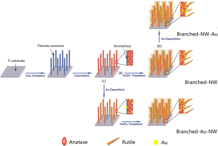
In this work, an architectural design was implemented to study the possible effects of the location of Au nanoparticles decorated on TiO2 nanoforests with anatase/rutile phase junctions. Simply altering the order of the fabrication step (Fig. 1), Au nanoparticles were located preferably either on the interface of anatase/rutile phase junctions, or on rutile branches, which in turn affected readily the photocatalytic efficiency towards photodegradations of rhodamine B in water under the illumination of either UV or visible light. Efforts were made to clarify the possible mechanisms that cause the distinct photocatalytic activity.
Figure 1.
A schematic diagram showing the formation of the branched TiO2 nanowires (a, Branched-NW), those after the Au-loading (b, Branched-NW-Au), and the branched TiO2 nanowires with an intermediate Au-loading (c, Branched-Au-NW).
Results and Discussions
Morphology and phase characterizations
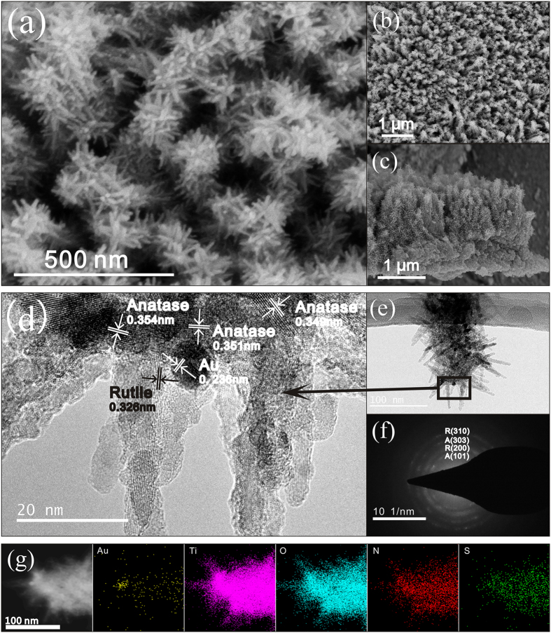
Supplementary Figure S1 shows FESEM images of the TiO2 nanoforests and those after Au-loading at various locations. It can be seen that quasi-aligned 1D branched nanowires covered homogeneously the Ti substrates. The Au-loading procedures induced no significant change in morphologies. Figure 2 illustrates FESEM, TEM, HRTEM, selected area electron diffraction (SAED), and EDS analysis results of the Branched-Au-NW (refer to Fig. 1 for the sample ID). The thickness of the TiO2 nanoforests is ca. 1 μm. An intermediate layer ca. 1 μm in thickness, which consisted of compact nanoparticles, can also be seen between the top layer and the substrate (Fig. 2a–c).
Figure 2.
(a) High and (b) low magnification top view, (c) cross-sectional FESEM images of the Branched-Au-NW; (d) HRTEM, (e) low-magnification TEM, and (f) the corresponding SAED of the Branched-Au-NW; (g) TEM image of another Branched-Au-NW and the corresponding EDS mapping images of Au, Ti, O, N and S.
The low-magnification TEM image shows clearly a typical branched nanowire that is decorated with Au nanoparticles (Fig. 2e). The average diameter of the nanorod branch is ca. 10 nm and the length is ca. 45 nm; while the Au particles have an approximately spherical shape that is 8–9 nm in diameter. The HRTEM image (Fig. 2d) exhibited that the backbone is formed by many tiny crystal grains with a lattice spacing of ca. 0.35 nm, which can be attributed to the (101) facet of anatase TiO2. The fringe with inter-plane spaces of ca. 0.32 nm on the branch can be discerned, which is attributed to the (110) crystal plane of rutile TiO2. Locating between the anatase backbone and the rutile branch, fringes with inter-plane spaces of ca. 0.235 nm can be seen clearly, which can be assigned to the (111) facet of Au. Hence, the HRTEM observations suggest that, for the Branched-Au-NW specimen, the well-crystalized single-crystalline rutile nanorods grew along the polycrystalline anatase TiO2 nanowires with an arbitrary angular orientation; whilst most Au nanoparticles located at the interface between the backbone and the branch, which contacted closely with both anatase and rutile. Figure 2f demonstrates the SAED pattern of the branched nanowire shown in Fig. 2e. Multi-rings characteristic of a mixture of anatase and rutile can be discerned, which is in good accordance with the HRTEM observations (Fig. 2d). The EDS mapping (Fig. 2g) suggests the homogenous distributions of Ti, O, N, and S throughout the Branched-Au-NW. A spot corresponding to an Au nanoparticle located between the anatase trunk and rutile branch can be discerned.
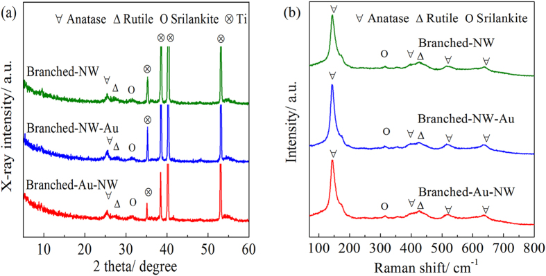
The crystal structure of the TiO2 nanoforests can find support from both XRD patterns and Raman spectra. XRD peaks corresponding to both anatase and rutile can be discerned, besides those arising from the metallic Ti substrates (Fig. 3a). It is not surprising that three specimens exhibited similar XRD patterns, indicating that the phase structure of TiO2 does not change after the deposition of gold nanoparticles. Trace srilankite TiO2 can also be discerned. The corresponding Raman spectrum suggests more clearly the coexistence of anatase, rutile, and srilankite (Fig. 3b). Both XRD (Fig. 3a) and SAED patterns (Fig. 2f) exhibit no signals corresponding to Au, which can be contributed to the minor amounts of Au nanoparticles. It is noted that only one peak appeared in both XRD patterns and Raman spectra, which is a weak proof of the existence of srilankite TiO2. However, a previous study35 revealed that, the srilankite TiO2 was detected on a low temperature derived TiO2 thin film. In that case, Raman peaks were identified at 168, 314, 354 and 425 cm−1, which have been contributed to srilankite TiO2. Also, the XRD peak located at ca. 31.5° was identified. Therefore, we believe it is safe to ascribe the present XRD peak located at ca. 31.5° (Fig. 3a) and the Raman peak located at ca. 314 cm−1 (Fig. 3b) to srilankite TiO2.
Figure 3.
(a) XRD patterns and (b) Raman spectra of the Branched-NW, Branched-NW-Au, and Branched-Au-NW.
Au contents
The atomic ratio of Au/Ti was measured by ICP-MS to be 0.36% and 0.51%, for the specimens of Branched-Au-NW and Branched-NW-Au, respectively. By using the defined Au-loading parameters (identical HAuCl4 solution and photo- reduction time), the Branched-Au-NW contained less Au nanoparticles when compared with the Branched-NW-Au. This may be contributed to the different phase compositions of the TiO2 films before Au-decorations. For the Branched-Au-NW, Au-loading was performed on poorly crystallized anatase TiO2 nanowires; whilst for the Branched-NW-Au, Au-loading was conducted on TiO2 nanoforests consisted of rutile TiO2 branches that grow radially around the poorly crystallized anatase TiO2 trunk34. It is well established that the anatase/rutile phase junctions facilitate charge separations24,25,26 and hence the photocatalytic efficiency for the Au-loading, which explained the higher content of gold nanoparticles decorated on Branched-NW-Au. It is also argued that Au nanoparticles form more easily on the rutile surface because a number of oxygen vacancies act as the crystal nucleation sites13.
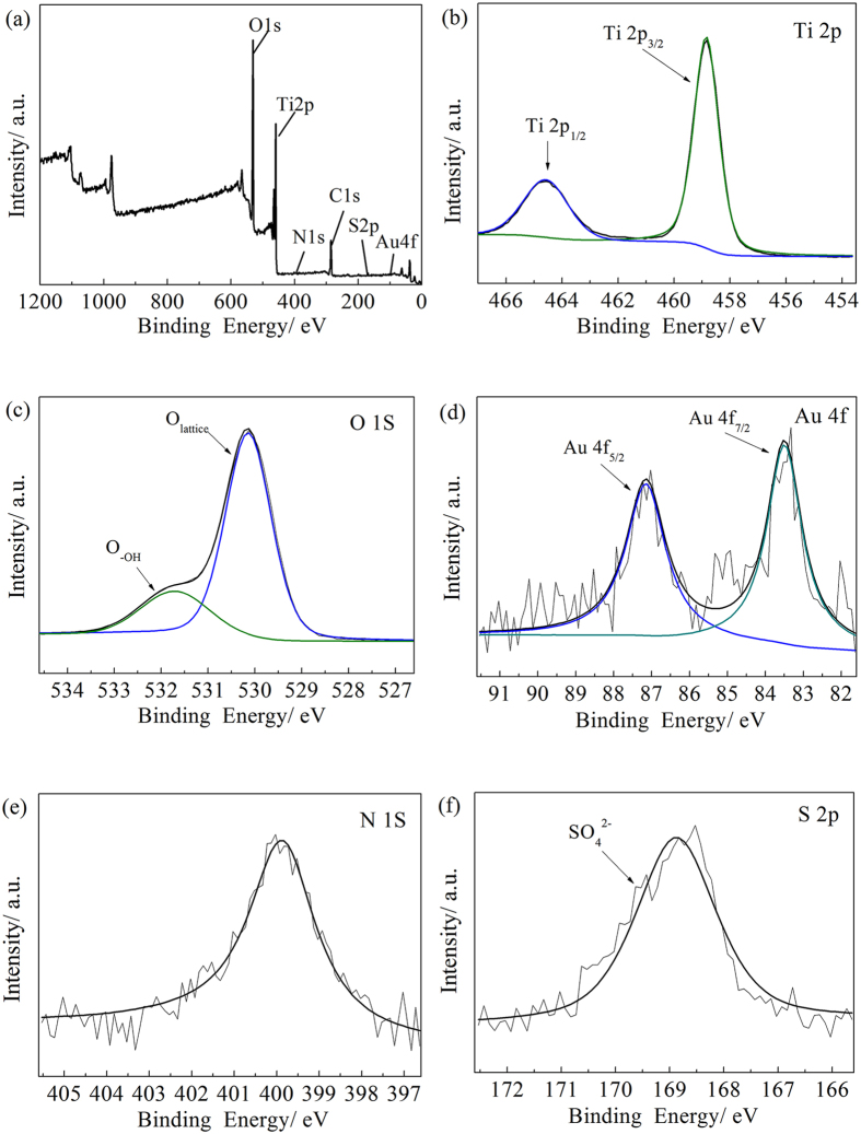
The surface compositions of the Branched-Au-NW were analyzed by XPS. Figure 4a shows that the surface layer of the Branched-Au-NW is composed of Ti, O, Au, N, and S, which is consistent to the EDS mapping images (Fig. 2g). The XPS spectrum of Ti 2p exhibits two dominant peaks, which correspond to Ti 2p1/2 at 464.6 eV and Ti 2p3/2 at 458.8 eV, indicating that Ti exist in the form of Ti4+. The separation between the two peaks is 5.8 eV (Fig. 4b), which is in agreement with the XPS data in the literature7. As shown in Fig. 4c, the O 1 s spectrum can be fitted by two components: a higher binding energy (BE) peak near the 531.7 eV, originating from the hydroxyl group (-OH)36, and a lower BE, in the vicinity of 530.1 eV, originating from the crystal lattice oxygen (Ti–O–Ti).
Figure 4.
(a) Wide scan and high-resolution XPS spectra of (b) Ti 2p, (c) O 1 s, (d) Au 4 f, (e) N 1 s, and (f) S 2p for the Branched-Au-NW.
The XPS spectrum of Au can be separated to two peaks, with a lower BE at 83.4 eV and a high BE at 87.1 eV, corresponding to Au 4f7/2 and Au 4f5/2, respectively (Fig. 4d). The typical Au 4f7/2 peak locates at 84.0 eV37 for bulk metallic gold; the slight shift in BE to a lower value can be ascribed to the redistribution of the electrons at the Au-TiO2 contact interfaces, because of the difference in the work function between Au (5.27 eV) and TiO2 (4.1 eV). This is an indication that Au nanoparticles interact with the adjacent TiO214,37,38. The electron transferring from TiO2 to Au nanoparticles is therefore facilitated, which increases the valence charge density of Au atoms and reduces the binding energy of Au in the TiO2 film.
The binding energy of N 1 s locates at ca. 399.8 eV, which can be assigned to nitrogen species bonding to various surface oxygen sites N-O, or N-N, and N-C bonds (Fig. 4e)39. The incorporation of N into the Branched-Au-NW film is believed to result from the decomposition of melamine during the fabrication of the titanate nanowires. After the H2SO4 treatment, sulfate ions also incorporate into the TiO2 film, which gave the XPS peak at 168.9 eV (Fig. 4f)36.
Table 1 lists the surface compositions of the two Au-decorated TiO2 nanoforests derived by the XPS analysis. The atomic Au/Ti ratio determined by the XPS analysis is ca. 0.27% for Branched-Au-NW, which is lower than that of Branched-NW-Au. The atomic Au/Ti ratios evaluated by XPS roughly agreed with that derived by the ICP-MS measurement.
Table 1. Surface compositions (in at. %) of Au-decorated TiO2 nanoforests obtained by XPS.
| C | N | S | O | Au | Ti | Au/Ti by XPS | Au/Ti by ICP | |
|---|---|---|---|---|---|---|---|---|
| Branched-NW-Au | 13.71 | 0.88 | 0.56 | 56.30 | 0.14 | 28.41 | 0.49% | 0.51% |
| Branched-Au-NW | 25.71 | 0.97 | 1.10 | 49.70 | 0.06 | 22.46 | 0.27% | 0.36% |
Growth of the TiO2 Nanoforests with Controlled Au-location
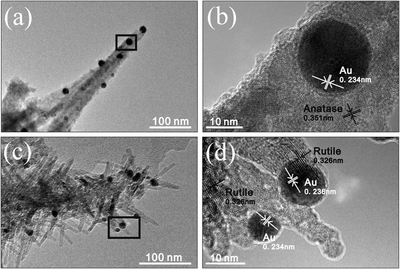
Figure 5a,b shows that, Au nanoparticles were intimately decorated on the surface of the poorly crystallized anatase TiO2 nanowires before the final H2SO4 treatment. That is to say, in the current tactic to synthesize Branched-Au-NW, Au nanoparticles were firstly deposited on the surface of the nanowires which were just subjected to the intermediate calcination. During the final H2SO4 treatment, the poorly crystallized anatase TiO2 nanowires were partly attacked by H2SO4, which released hydrated Ti(IV) ions into the acid solution34. Once the Ti(IV) ions accumulated to a critical concentration, nucleation and subsequent growth of rutile TiO2 branches around the anatase TiO2 trunk occurred. It seems that the edges formed between the nanowires and the decorated Au nanoparticles provide heterogeneous nucleation sites for the TiO2 branches, which resulted in the preferred locations of the Au nanoparticles around the junctions of the anatase trunk and rutile branch.
Figure 5.
(a,b) TEM and HRTEM images of the Au-decorated nanowires just before the final H2SO4 treatment; (c,d) TEM and HRTEM images of the Branched-NW-Au.
When the Au-decoration procedure was moved to be the final step, the Au nanoparticles did not locate preferably on the anatase/rutile phase junctions any more. Because of certain “tip” effects, most of Au nanoparticles located on the surface of the rutile branch (Fig. 5c,d), rather than on the interface of rutile branch and anatase backbone. In addition, for the Branched-NW film, because the anatase trunk is surrounded by rutile branches, Au nanoparticles had a higher possibility to sit on rutile. Therefore, simply altering the Au-loading order fulfilled the control in the location of Au nanoparticles, which affects readily the resultant photocatalytic performance of the Au-decorated TiO2 nanoforests, as will be discussed later.
PL and UV-Vis DRS Characterizations
Figure 6 shows the PL spectra of the three specimens, all of which possessed a feature that consists of two emission peaks in the UV-visible range. The UV emission centered at 400 nm is related to the electron transition from the valence band and the conduction band38, and the emission centered at around 608 nm may arise from the recombination of photo-generated holes with the electrons in singly occupied oxygen vacancies40. It can be seen that, the intensity of UV emission decreased in the order of Branched-NW, Branched-NW-Au, and Branched-Au-NW. Therefore, the Au-decoration suppresses the charge recombination, which is closely related to the location of Au nanoparticles.
Figure 6. Ambient PL spectra of the Branched-NW, Branched-NW-Au, and Branched-Au-NW.
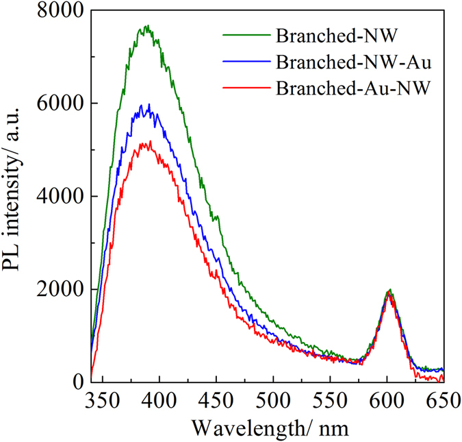
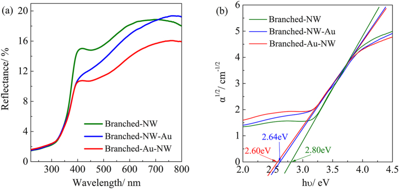
Figure 7a illustrates the UV-Vis diffuse reflectance spectra collected from the three specimens. The Branched-Au-NW film exhibited the lowest reflectance over the visible light region, which suggests the highest visible light harvesting capability when compared with the Branched-NW and the Branched-NW-Au. The increasing absorption can be ascribed to the LSPR effect arising from Au nanoparticles. A strong oscillation of the metal’s surface free electrons with the varying electric field of the incident light absorbs the energy of photon and conveys to electrons to form surface plasmons, which decay to hot electron-hole pairs; as a result, the light response of the Au-decorated specimens in the visible light region is enhanced41,42.
Figure 7.
(a) UV-Vis diffuse reflectance spectra of the Branched-NW, Branched-NW-Au, and Branched-Au-NW; (b) the spectra in an α1/2~hν coordinate to evaluate the band gap.
Assuming an indirect transition between band gaps, the band gaps of TiO2 can be estimated by extrapolating the tangent line in the plot of α1/2 against hυ43, where α is the absorption coefficient and the hυ is the photon energy. Figure 7b demonstrates that the Branched-Au-NW possessed an indirect band gap of 2.61 eV, which is lower than the value of 2.64 eV and 2.80 eV determined for the Branched-NW-Au and Branched-NW, respectively. The relatively lower band gap of 2.80 eV for Branched-NW, when compared with bulk TiO2 (3.2 eV for anatase and 3.0 eV for rutile), can be contributed to the N-doping (Fig. 4e) and the significant oxygen deficiency (Fig. 4c) arising from the low-temperature synthesis route. A DFT calculation by Jia et al. revealed that, the band gap of a N, S-codoped TiO2 can be narrowed to be. 2.77 eV44. The further red-shift for the Au-decorated films was attributed mainly to the interaction of Au and TiO2, which might introduce an intra-gap level inside the band gap of TiO237. Considering the relatively lower Au content for the Branched-Au-NW (0.36%) when compared with the Branched-NW-Au (0.51%), as determined by ICP-MS, both the higher light harvesting capability and the slightly lower band gap once again convinced the importance of the Au-location. A rough explanation for the enhanced LSPR arising from Au nanoparticles in Branched-Au-NW could be that the contacting surface area between Au and TiO2 is higher than that in Branched-NW-Au.
Photocatalytic Activity
Photocatalytic activities of the three TiO2 nanoforests were evaluated by decomposing rhodamine B in water under UV and visible light illuminations, respectively. In absence of any photocatalysts, about 95% and 97% dye molecules remained after 60 min of UV and visible light illuminations. The dark absorption capacity is enhanced after the Au-decoration, which can be ascribed to the interaction of Au and dye molecules. For comparison purpose, thin films of Degussa P25 TiO2 nanoparticles (ca. 3.0 μm in thickness, refer to the literature45 for the fabrication route), which are generally adopted as a benchmark, were also subjected to the photocatalytic activity evaluations under the identical conditions.
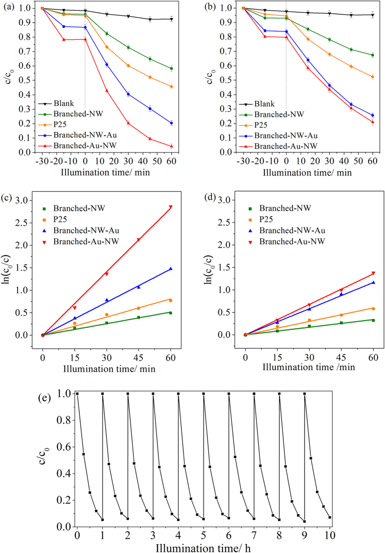
The HAuCl4 concentrations adopted for the Au-decoration were firstly optimized (Supplementary Figure S2). It illustrates that, for both Au-decorated films, there is an optimum HAuCl4 concentration (0.040 mM). It can thus be inferred that, certain amounts of Au nanoparticles introduced to the TiO2 nanoforests enhanced the photocatalytic activity. However, excess Au nanoparticles aggregate to serve as recombination centers for photogenerated charges, leading to an inferior performance46. Figure 8a,b indicates the photodegradation curves, which can be fitted well assuming a pseudo-first-order kinetics47,
Figure 8.
Photodegradation curves of rhodamine B in water in the presence of the P25, Branched-NW, Branched-NW-Au, and Branched-Au-NW, under (a) UV light, and (b) visible light illumination. (c,d) Represent the corresponding fitting results assuming a pseudo-first order reaction. The cycling performance of the Branched-Au-NW is illustrated in (e), under the UV light illumination.
 |
where c is the dye concentration after illumination for a duration t, c0 is the dye concentration after the dark adsorption, and k is the pseudo-first-order reaction rate constant, which can be obtained by the slope of the straight lines through zero. Figure 8c,d shows the corresponding fitting results and Table 2 lists the reaction rate constants, which were derived using the average data obtained from three repetitive tests. Under the UV light illumination, the reaction rate constant increased from 0.86 to 2.5 × 10⁻² min−1 after the Au-decoration of the Branched-NW. Simply controlling the location of the Au nanoparticles to distribute mainly along the anatase/rutile phase junctions, the reaction rate constant further increased to 4.7 × 10⁻² min−1, which is nearly 5 times higher when compared with the Branched-NW specimen. The Au location affects also the photocatalytic activity under the visible light illumination.
Table 2. Reaction rate constants (k, × 10−2 min−1) for the different organics in the presence of various TiO2 nanoforests and under the illumination of UV and visible light.
| Films | P25 | Branched-NW | Branched-NW-Au | Branched-Au-NW |
|---|---|---|---|---|
| UV + RhB | 1.4 | 0.86 | 2.5 | 4.7 |
| UV+ p-nitrophenol | / | 0.11 | 0.16 | 0.22 |
| UV+ phenol | / | 0.07 | 0.11 | 0.17 |
| Vis + RhB | 1.0 | 0.57 | 1.9 | 2.3 |
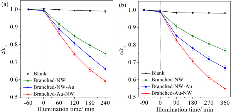
Photocatalytic degradations of p-nitrophenol and phenol under the UV light illumination, in the presence of the various Au/TiO2 films were also evaluated. Figure 9 and Table 2 show that, the same trend can be discerned. Therefore, it can be concluded that, the photocatalytic activity of the branched TiO2 film was enhanced after the Au decoration and the position of Au nanoparticles really has a great impact on the photocatalytic activity. Due to the insufficient efficiency of the present Au/TiO2 films under the visible light illumination, the photocatalytic degradations of p-nitrophenol and phenol under visible light is not presented in the current investigation. Photosensitive materials are argued to be not suitable as probe chemicals for photocatalytic activity tests, especially those for evaluation of activity under visible light48. Further study is thus demanded to disclose the effects of Au-locations on photodegradations of organics besides rhodamine B molecules.
Figure 9.
Photodegradation curves of (a) p-nitrophenol and (b) phenol under UV light illumination.
The trapping experiment was employed to disclose the possible photocatalysis mechanism (Supplementary Figure S3). It is inferred that OH•, h+, and O2•− all contribute to the photocatalytic reaction. The superoxide radicals O2•− are the major active species responsible for this photocatalytic oxidation reaction, followed by the photogenerated holes h+, and the hydroxyl radical OH•.
Mechanism
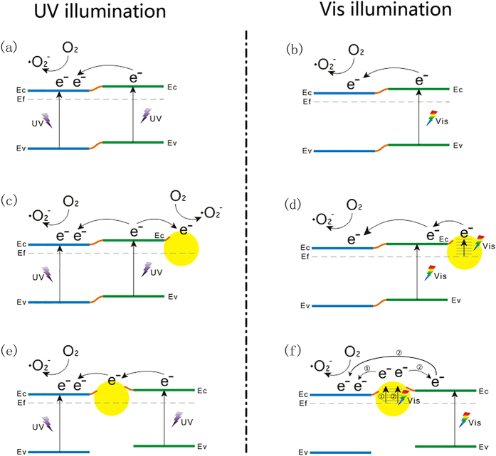
Figure 10 provides a possible explanation for the beneficial effects arising from Au nanoparticles located between the anatase/rutile phase junctions in the present 1D branched TiO2 nanowires. Because Supplementary Figure S3 indicates that superoxide radicals O2•− contribute the most to the photocatalytic reaction; only the degradation route via O2•− is presented in Fig. 10. It is well established that anatase/rutile phase junction effectively suppresses the recombination of photogenerated electron-hole pairs30,49,50,51; however, the exact charge transfer direction still remains a controversy25,52. Herein, the energetic alignment of the band edges of the anatase and rutile polymorphs of TiO2 suggested recently by Scanlon et al. is adopted52.
Figure 10.
Schematic images showing the enhanced photocatalytic efficiency arising from the intermediate Au-loading for the TiO2 nanoforests under the illumination of (a,c,e) UV and (b,d,f) visible light: (a,b) Branched-NW; (c,d) Branched-NW-Au; (e,f) Branched-Au-NW. For simplicity, the degradation route via photogenerated holes h+ and hydroxyl radicals OH• is not shown.
UV Light Illumination
As illustrated in Fig. 10a, under UV light irradiation, photogenerated electrons transfer from rutile to anatase, which results in an enhanced charge separation rate and hence improved photocatalytic activity. In addition, it has been proved that O2 reduction by the photo-induced electrons on the rutile surface is inefficient because of the low affinity between the surface and O2. In contrast, anatase is more active for O2 reduction13. As a result, the electron transfer from rutile to anatase accelerates the photodegradation procedure, especially for which superoxide radicals O2•− play the key role (Supplementary Figure S3).
In case that the TiO2 nanoforests were subjected to a final Au-decoration (Branched-NW-Au), Au nanoparticles prefer to locate on rutile surfaces (Fig. 5c,d). Because of the Shottky barrier between Au and TiO2 semiconductor, the photoexcited electrons from rutile will also transfer to Au nanoparticles13,14, except for the migration to anatase. Thus, Au nanoparticles act as the electrons accepting species at the Au/rutile interface, suppressing further the recombination of photogenerated charges (Fig. 10c). The reaction rate constant thus increased from 0.86 to 2.5 × 10⁻² min−1 (UV + RhB, Table 2). When Au nanoparticles are loaded on the interface between anatase and rutile in the TiO2 nanoforests, as for the Branched-Au-NW, they provide a path for rapid and effective electron migrations from rutile to anatase53, which significantly enhances the positive effects arising from the anatase/rutile phase junction (Fig. 10e). Such a function is more effective for the charge separation, contributing to an even higher reaction rate constant of 4.7 × 10⁻² min−1 (UV + RhB, Table 2). The enhanced charge separation is supported by the PL measurement (Fig. 6).
Visible Light Illumination
In the current investigation, the Branched-NW possessed a band gap of 2.80 eV, which corresponds to a wavelength of ca. 440 nm (Fig. 7); therefore, under the illumination of visible light (>420 nm), it is possible for the rutile branch to absorb the photons with appropriate energy to initiate the photocatalytic reaction (Fig. 10b). The additional electrons arising from the LSPR effect of Au nanoparticles, which may also transfer to anatase to initiate the photodegradation reaction there (Fig. 10d), explains the increased reaction rate constant from 0.57 × 10⁻² min−1 for Branched-NW to 1.9 × 10⁻² min−1 for Branched-NW-Au (Vis + RhB, Table 2). The further enhanced reaction rate constant for Branched-Au-NW (2.3 × 10⁻² min−1) is in good accordance with Tsukamoto et al.13. Here, Au nanoparticles locate preferably at the interface of anatase/rutile, upon the visible light illumination, the LSPR induced electrons transfer from Au nanoparticles to the tightly bound rutile and then through the phase junction to well-conjugated anatase, where the electrons react with surface adsorbed O2 to form O2•− to assist photodegradations of rhodamine B in water (Path 2, Fig. 10f)13,14. Because Au nanoparticles contact with both anatase and rutile (Fig. 2d), we believe that, photogenerated electrons arising from the LSPR effect may also transfer directly to the adjacent anatase, which additionally contribute to the enhanced photocatalytic activity (Path 1, Fig. 10f).
Cycling Performance and mineralization capability
Long-term stability is a major concern of photocatalysts. Figure 8e shows the cycling performance of the Branched-Au-NW film. For up to 10 cycles, no remarkable decay can be discerned, which evidenced the excellent stability of the present Au-decorated TiO2 nanoforests. The present Branched-Au-NW film is also capable of inducing deep mineralization of organics in water after UV illumination for certain durations. A total organic carbon (TOC) reduction of ca. 64.2% was achieved for the rhodamine B solution after the UV light illumination for 1 h when assisted by the Branched-Au-NW film. The liquid chromatography (LC) spectra (Supplementary Figure S4), which were utilized to determine the phenol’s concentration during the photodegradation procedure under the UV illumination, shows that, although the P25 film has a higher efficiency on photodegradations of phenol, less by-products can be discerned for the Au/TiO2 photocatalyst (Branched-Au-NW). This further supports the capability of the present Au/TiO2 photocatalyst to achieve a deep mineralization of organics in water.
Conclusion
Titania nanoforests, which consisted of anatase nanowires surrounded by radially grown rutile branches, were synthesized on metallic Ti substrates through multi-steps of H2O2 oxidation, intermediate calcination, and sulfuric acid treatment. A photo-reduction technique was then applied to decorate Au nanoparticles. Altering the order in the fabrication step is effective in controlling the preferred location of Au nanoparticles. Under the UV light illumination, Au nanoparticles, which located preferably at the interface of anatase/rutile, magnify the beneficial effects arising from the anatase/rutile phase junctions; whilst under the visible light illumination, the LSPR effect followed by the consecutive electron transfer results in improved photocatalysis. This finding evidenced the feasibility to further improve photocatalytic activity of multiple-phases semiconductor arrays with one-dimensional nanostructures through carefully controlling the location of noble metals.
Methods
Synthesis of TiO2 Nanoforests
Figure 1 demonstrates schematically the three steps in sequence to synthesize TiO2 nanoforests (abbreviated as Branched-NW hereafter) on metallic Ti substrates, that is, H2O2 oxidation, intermediate calcination, and H2SO4 treatment34. In a typical synthesis, each cleaned Ti plate (5 × 5 × 0.01 cm3 in size) was immersed in 50 mL of 8.8 M H2O2 solution containing 16 mM melamine (C3H6N6) and 29 mM HNO3, which was maintained at 80 °C for 48 h to grow hydrogen titanate (H2Ti5O11) nanowire array on the surface. The Ti plate was then taken out, rinsed in sequence with ethanol and deionized water, and subjected to an intermediate thermal treatment in air at 260 °C for 1 h to decompose H2Ti5O11 to amorphous TiO2 embedded with poorly crystallized anatase. The Branched-NW was achieved by a final treatment in 50 mL of 5 mM H2SO4 aqueous solution at 80 °C for 48 h, which induced the formations of rutile TiO2 branches that grow radially around the poorly crystallized anatase TiO2 trunk34.
Decoration of Au Nanoparticles at Controlled Locations
Au nanoparticles were decorated on Branched-NW via a photo-reduction method54. 0.44 mg of HAuCl4 (corresponding to an initial concentration of ca. 0.040 mM), methanol (0.2 mL), and deionized water (34 mL) were mixed in a beaker. Branched-NW was immersed into the solution, which was bubbled with pure nitrogen gas, and then subject to the UV light (5.0 mW/cm2) irradiation for 5 min. The specimens were dried at 80 °C in an oven overnight, which were designated as Branched-NW-Au hereafter. To vary the location of the Au nanoparticles, in a parallel experiment, the order in Au-deposition and H2SO4 treatment was exchanged. The specimens were noted as Branched-Au-NW.
Characterizations
Surface morphology of thin films was observed using a field emission scanning electron microscopy (FESEM, Hitachi S-4800) and a transmission electron microscopy (TEM, FEI, Tecnai G2 F20 S-TWIN, with EDS capabilities). To prepare the samples for TEM characterizations, the TiO2 nanoforests were detached off from the Ti plate and then placed on a carbon pre-coated copper grid. The X-ray diffraction (XRD) tests were conducted on a Rigaku D/max-3B diffractmeter with Cu Kα radiation (λ = 0.154056 nm), operated at 40 kV, 36 mA. Raman spectra were collected using an Almega dispersive Raman system (Nicolet) and a Nd:YAG intracavity doubled laser operating at 532 nm with an incident power of 10 mW. The atomic ratio of Au and Ti was measured with inductively coupled plasma mass spectrometry (ICP-MS, XSeries II, Thermo Fisher Scientific, USA). For the ICP-MS measurement, the Au-decorated TiO2 nanoforests were scratched off and dissolved in aqua regia. The X-ray photoelectron spectroscopy (XPS) spectra were collected using an ESCA spectrometer (S-Probe ESCA SSX-100S, Fisons Instrument) and monochromatized Al Kα X-ray (1486.8 eV) irradiation. The binding energy was normalized to the C 1 s energy (284.6 eV) for adventitious hydrocarbons as the indirect standard. The UV-Vis diffuse reflectance spectra were measured using a UV-Vis near-infrared spectrometer (UV-3150, Shimadzu). The ambient photoluminescence (PL) emission spectra characterizations were carried out on a fluorescence spectrophotometer (HITACHI F-4500) with an excited wavelength of 360 nm.
Photocatalytic Activity Evaluations
Titania thin films (2.5 × 2.5 cm2 in size) were used to assist photocatalytic degradations of rhodamine B, p-nitrophenol and phenol in water (25 mL) in a Pyrex reactor with a water jacket, which is illustrated schematically in Supplementary Figure S5. Three repetitive tests were conducted to give the average value and error bar (standard deviation) as illustrated in the corresponding degradation curves. The initial concentration of rhodamine B is 0.005 mmol/L, while the initial concentrations of p-nitrophenol and phenol are 5 ppm and 10 ppm, respectively. The UV irradiation was provided by an 18 W UV lamp and the visible light by a 500 W Xe-lamp with a 420 nm UV-cut filter. The UV and visible light intensity reaching the sample was measured to be ca. 5.0 mW/cm2 and 200.0 mW/cm2, respectively, using irradiance meters (model: UV-A and FZ-A, Beijing Normal university, China, measured for the wavelength of 365 nm for UV light and 400–1000 nm for the visible light). The solution was stirred and exposed to air during the photocatalytic reaction. The change in the rhodamine B and p-nitrophenol concentrations was monitored with a UV-Vis spectrophotometer (UV-1800PC, Shanghai Mapada, Shanghai, China) at a wavelength of 553 nm and 317 nm, respectively. The phenol concentration was analyzed by liquid chromatography on a Wufeng LC100 (WondaCract C18-ODS column, and 50% CH3OH aqueous solution as an eluent). The total organic carbon (TOC) of rhodamine B was measured with a Total Organic Carbon Analyzer (Multi N/C 3100).
To investigate the effects of the active species generated during the photocatalytic reaction under the UV illumination and in the presence of the Branched-Au-NW, the free radicals capture experiments were conducted55. The three major oxidants involved in photodegradations of organics in water, that is, hydroxyl radical (OH•), hole (h+), and superoxide radical (O2•−), were trapped by adding 0.5 mL of tert-butanol (t-BuOH), 0.1 mM of ammonium oxalate (AO), and 0.5 mM of 1, 4-benzoquinone (BQ), respectively, into the rhodamine B solutions.
Additional Information
How to cite this article: Yu, Y. et al. UV and visible light photocatalytic activity of Au/TiO2 nanoforests with Anatase/Rutile phase junctions and controlled Au locations. Sci. Rep. 7, 41253; doi: 10.1038/srep41253 (2017).
Publisher's note: Springer Nature remains neutral with regard to jurisdictional claims in published maps and institutional affiliations.
Supplementary Material
Acknowledgments
We gratefully acknowledge financial support for this work from Department of Science Technology of Zhejiang Province (No. 2015C31034) and National Natural Science Foundation of China (No. 51502065).
Footnotes
Author Contributions J.M.W. and W.W. conceived the concept and experiments. Y.Y. and X.Y.Q. carried out the materials synthesis and characterizations. J.B.L. carried out the TEM analysis. Y.Y. and J.M.W. co-wrote the paper. All authors discussed the results and commented on the manuscript.
References
- Chen X. & Mao S. S. Titanium Dioxide Nanomaterials: Synthesis, Properties, Modifications, and Applications. Chem. Rev. 107, 2891–2959 (2007). [DOI] [PubMed] [Google Scholar]
- Moniz S. J. A., Shevlin S. A. & Martin D. J. Visible-Light Driven Heterojunction Photocatalysts for Water Splitting–A Critical Review. Energ. Environ. Sci. 8, 731–759 (2015). [Google Scholar]
- Xiang Q., Cheng B. & Yu J. Graphene-Based Photocatalysts for Solar-Fuel Generation. Angew. Chem. Int. Ed. 54, 11350–11366 (2015). [DOI] [PubMed] [Google Scholar]
- Ghosh S., Kouamé N. A. & Ramos L. Conducting Polymer Nanostructures for Photocatalysis under Visible Light. Nat. mater. 14, 505–511 (2015). [DOI] [PubMed] [Google Scholar]
- Bridewell V. L., Alam R. & Karwacki C. J. CdSe/CdS Nanorod Photocatalysts: Tuning the Interfacial Charge Transfer Process through Shell Length. Chem. Mater. 27, 5064–5071 (2015). [Google Scholar]
- Fujishima A. & Honda K. Electrochemical Photolysis of Water at A Semiconductor Electrode. Nature 238, 37–38 (1972). [DOI] [PubMed] [Google Scholar]
- Banerjee B., Amoli V. & Maurya A. Green Synthesis of Pt-Doped TiO2 Nanocrystals with Exposed (001) Facets and Mesoscopic Void Space for Photo-Splitting of Water under Solar Irradiation. Nanoscale 7, 10504–10512 (2015). [DOI] [PubMed] [Google Scholar]
- Choi Y., Kim H. & Moon G. Boosting up the Low Catalytic Activity of Silver for H2 Production on Ag/TiO2 Photocatalyst: Thiocyanate as A Selective Modifier. ACS Catal. 6, 821–828 (2016). [Google Scholar]
- Fujiwara K., Müller U. & Pratsinis S. E. Pd Subnano-Clusters on TiO2 for Solar-Light Removal of NO. ACS Catal. 3, 1887–1893 (2016) [Google Scholar]
- Zhang D. Q. et al. Au Nanoparticles Enhanced Rutile TiO2 Nanorod Bundles with High Visible-Light Photocatalytic Performance for NO Oxidation. Appl. Catal. B-Environ. 147, 610–616 (2014). [Google Scholar]
- Nalbandian M. J. et al. Tailored Synthesis of Photoactive TiO2 Nanofibers and Au/TiO2 Nanofiber Composites: Structure and Reactivity Optimization for Water Treatment Applications. Environ. Sci. Technol. 49, 1654–1663 (2015). [DOI] [PubMed] [Google Scholar]
- McEntee M., Stevanovic A., Tang W. J., Neurock M. & Yates J. T. Electric Field Changes on Au Nanoparticles on Semiconductor Supports-the Molecular Voltmeter and Other Methods to Observe Adsorbate-Induced Charge-Transfer Effects in Au/TiO2 Nanocatalysts. J. Am. Chem. Soc. 137, 1972–1982 (2015). [DOI] [PubMed] [Google Scholar]
- Tsukamoto D. et al. Gold Nanoparticles Located at the Interface of Anatase/Rutile TiO2 Particles as Active Plasmonic Photocatalysts for Aerobic Oxidation. J. Am. Chem. Soc. 134, 6309–6315 (2012). [DOI] [PubMed] [Google Scholar]
- Wen Y., Liu B. T., Zeng W. & Wang Y. H. Plasmonic Photocatalysis Properties of Au Nanoparticles Precipitated Anatase/Rutile Mixed TiO2 Nanotubes. Nanoscale 5, 9739–9746 (2013). [DOI] [PubMed] [Google Scholar]
- Cheng H., Fuku K. & Kuwahara Y. Harnessing Single-Active Plasmonic Nanostructures for Enhanced Photocatalysis under Visible Light. J. Mater. Chem. A 3, 5244–5258 (2015). [Google Scholar]
- Ma L. et al. Synthesis of Dumbbell-Like Gold-Metal Sulfide Core-Shell Nanorods with Largely Enhanced Transverse Plasmon Resonance in Visible Region and Efficiently Improved Photocatalytic Activity. Adv. Funct. Mater. 25, 898–904 (2015). [Google Scholar]
- Zielinska-Jurek A. et al. Preparation and Characterization of Monometallic (Au) and Bimetallic (Ag/Au) Modified-Titania Photocatalysts Activated by Visible Light. Appl. Catal. B-Environ. 101, 504–514 (2011). [Google Scholar]
- Kimura K., Naya S. & Jin-nouchi Y. TiO2 Crystal Form-Dependence of the Au/TiO2 Plasmon Photocatalyst’s Activity. J. Phys. Chem. C 116, 7111–7117 (2012). [Google Scholar]
- Murdoch M., Waterhouse G. I. N. & Nadeem M. A. The Effect of Gold Loading and Particle Size on Photocatalytic Hydrogen Production from Ethanol over Au/TiO2 Nanoparticles. Nat. Chem. 3, 489–492 (2011). [DOI] [PubMed] [Google Scholar]
- Tanaka A., Sakaguchi S. & Hashimoto K. Preparation of Au/TiO2 with Metal Cocatalysts Exhibiting Strong Surface Plasmon Resonance Effective for Photoinduced Hydrogen Formation under Irradiation of Visible Light. ACS Catal. 3, 79–85 (2012). [Google Scholar]
- Bian Z., Tachikawa T. & Zhang P. Au/TiO2 Superstructure-Based Plasmonic Photocatalysts Exhibiting Efficient Charge Separation and Unprecedented Activity. J. Am. Chem. Soc. 136, 458–465 (2013). [DOI] [PubMed] [Google Scholar]
- Priebe J. B., Radnik J. & Lennox A. J J. Solar Hydrogen Production by Plasmonic Au–TiO2 Catalysts: Impact of Synthesis Protocol and TiO2 Phase on Charge Transfer Efficiency and H2 Evolution Rates. ACS Catal. 5, 2137–2148 (2015). [Google Scholar]
- Li H., Zhou Y. & Tu W. State-of-the-Art Progress in Diverse Heterostructured Photocatalysts toward Promoting Photocatalytic Performance. Adv. Funct. Mater. 25, 998–1013 (2015). [Google Scholar]
- Kafizas A., Wang X. & Pendlebury S. R. Where Do Photo-Generated Holes Go in Anatase: Rutile TiO2? A Transient Absorption Spectroscopy Study of Charge Transfer and Lifetime. J. Phys.Chem. A 120, 715–723 (2016). [DOI] [PubMed] [Google Scholar]
- Zhao W. N., Zhu S. C. & Li Y. F. Three-Phase Junction for Modulating Electron–Hole Migration in Anatase–Rutile Photocatalysts. Chem. Sci. 6, 3483–3494 (2015). [DOI] [PMC free article] [PubMed] [Google Scholar]
- Sun X., Dai W. & Wu G. Evidence of Rutile-to-Anatase Photo-Induced Electron Transfer in Mixed-Phase TiO2 by Solid-State NMR Spectroscopy. Chem. Commun. 51, 13779–13782 (2015). [DOI] [PubMed] [Google Scholar]
- Zhang Y., Pei Q. & Liang J. Mesoporous TiO2-Based Photoanode Sensitized by BiOI and Investigation of Its Photovoltaic Behavior. Langmuir 31, 10279–10284 (2015). [DOI] [PubMed] [Google Scholar]
- Han C., Wang Y. & Lei Y. In Situ Synthesis of Graphitic-C3N4 Nanosheet Hybridized N-Doped TiO2 Nanofibers for Efficient Photocatalytic H2 Production and Degradation. Nano Res. 8, 1199–1209 (2015). [Google Scholar]
- Liu L., Yang W. & Sun W. Creation of Cu2O@ TiO2 Composite Photocatalysts with p–n Heterojunctions Formed on Exposed Cu2O Facets, Their Energy Band Alignment Study, and Their Enhanced Photocatalytic Activity under Illumination with Visible Light. ACS Appl. Mater. Inter. 7, 1465–1476 (2015). [DOI] [PubMed] [Google Scholar]
- Ge. M. et al. A Review of One-Dimensional TiO2 Nanostructured Materials for Environmental and Energy Applications. J. Mater. Chem. A 4, 6772–6801 (2016). [Google Scholar]
- Sheng X., He D., Yang J., Zhu K. & Feng X. Oriented Assembled TiO2 Hierarchical Nanowire Arrays with Fast Electron Transport Properties. Nano Lett. 14, 1848–1852 (2014). [DOI] [PubMed] [Google Scholar]
- Wu W. Q., Xu Y. F., Rao H. S., Su C. Y. & Kuang D. B. Multistack Integration of Three-Dimensional Hyperbranched Anatase Titania Architectures for High-Efficiency Dye-Sensitized Solar Cells. J. Am. Chem. Soc. 136, 6437–6445 (2014). [DOI] [PubMed] [Google Scholar]
- Liu C., Tang J., Chen H. M., Liu B. & Yang P. A Fully Integrated Nanosystem of Semiconductor Nanowires for Direct Solar Water Splitting. Nano Lett. 13, 2989–2992 (2013). [DOI] [PubMed] [Google Scholar]
- Wu J. M. & Yin J. X. A Facile Solution-Based Approach to A Photocatalytic Active Branched One-Dimensional TiO2 Array. RSC Adv. 5, 3465–3469 (2015). [Google Scholar]
- Sun J. & Wu J. M. A Comparative Study on Photocatalytic Activity of Titania Nanowires Subjected to High-Temperature Calcination and Low-Temperature HCl Treatment. Sc. Adv. Mater. 5, 549–556 (2013). [Google Scholar]
- Sun J., Wen W. & Wu J. M. Low-Temperature Transformation of Titania Thin Films from Amorphous Nanowires to Crystallized Nanoflowers for Heterogeneous Photocatalysis. J. Am. Ceram. Soc. 96, 2109–2116 (2013). [Google Scholar]
- Zhu Y. F. et al. Fabrication and Photoelectrochemical Properties of ZnS/Au/TiO2 Nanotube Array Films. Phys. Chem. Chem. Phys. 15, 4041–4048 (2013). [DOI] [PubMed] [Google Scholar]
- Su F. L. et al. Dendritic Au/TiO2 Nanorod Arrays for Visible-Light Driven Photoelectrochemical Water Splitting. Nanoscale 5, 9001–9009 (2013). [DOI] [PubMed] [Google Scholar]
- Li D. Z. et al. New Synthesis of Excellent Visible-Light TiO2−xNx Photocatalyst Using a Very Simple Method. J. Solid State Chem. 180, 2630–2634 (2007). [Google Scholar]
- Lai L. L. & Wu J. M. A Facile Solution Approach to W, N Co-Doped TiO2 Nanobelt Thin Films with High Photocatalytic Activity. J. Mater. Chem. A 3, 15863–15868 (2015). [Google Scholar]
- Zhang X. M., Chen Y. L., Liu R. S. & Tsai D. P. Plasmonic Photocatalysis. Rep. Prog. Phys. 76, 4 (2013). [DOI] [PubMed] [Google Scholar]
- Zhang X., Liu Y. & Kang Z. H. 3D Branched ZnO Nanowire Arrays Decorated with Plasmonic Au Nanoparticles for High-Performance Photoelectrochemical Water Splitting. ACS Appl. Mat. Inter. 6, 4480–4489 (2014). [DOI] [PubMed] [Google Scholar]
- Sanchez E. & Lopez T. Effect of the Preparation Method on the Band Gap of Titania and Platinum-Titania Sol-Gel Materials. Mater. Lett. 25, 271–275 (1995). [Google Scholar]
- Jia L. C. et al. Enhanced Visible-Light Photocatalytic Activity of Anatase TiO2 through N and S Codoping. Appl. Phys. Lett. 98, 211903 (2011). [Google Scholar]
- Wu J. M., Zhang T. W. & Zeng Y. W. Large-Scale Preparation of Ordered Titania Nanorods with Enhanced Photocatalytic Activity. Langmuir 21, 6995–7002 (2005). [DOI] [PubMed] [Google Scholar]
- Li H. X. et al. Mesoporous Au/TiO2 Nanocomposites with Enhanced Photocatalytic Activity. J. Am. Chem. Soc. 129, 4538–4539 (2007). [DOI] [PubMed] [Google Scholar]
- Wu J. M. & Zhang T. W. Photodegradation of Rhodamine B in Water Assisted by Titania Films Prepared through A Novel Procedure. J. Photochem. Photobiol. A-Chem. 162, 171–177 (2004). [Google Scholar]
- Yan X. L., Ohno T., Nishijima K., Abe R. & Ohtani B. Is Methylene Blue an Appropriate Substrate for a Photocatalytic Activity Test? A Study with Visible-Light Responsive Titania. Chem. Phys. Lett. 429, 606–610 (2006). [Google Scholar]
- Zhang J., Xu Q., Feng Z., Li M. & Li C. Importance of the Relationship between Surface Phases and Photocatalytic Activity of TiO2. Angew. Chem. Int. Ed. 47, 1766–1769 (2008). [DOI] [PubMed] [Google Scholar]
- Xu Q. et al. Enhancing Hydrogen Production Activity and Suppressing CO Formation from Photocatalytic Biomass Reforming on Pt/TiO2 by Optimizing Anatase-Rutile Phase Structure. J. Catal. 278, 329–335 (2011). [Google Scholar]
- Hurum D. C., Agrios G. A. & Gary A. Kimberly Explaining the Enhanced Photocatalytic Activity of Degussa P25 Mixed-Phase TiO2 Using EPR. J. Phys. Chem. B 107, 4545–4549 (2003). [Google Scholar]
- Scanlon D. O. et al. Band Alignment of Rutile and Anatase TiO2. Nat. Mater. 12, 798–801 (2013). [DOI] [PubMed] [Google Scholar]
- Li J. T. et al. Solar Hydrogen Generation by a CdS-Au-TiO2 Sandwich Nanorod Array Enhanced with Au Nanoparticle as Electron Relay and Plasmonic Photosensitizer. J. Am. Chem. Soc. 136, 8438–8449 (2014). [DOI] [PubMed] [Google Scholar]
- Zheng Z. K. et al. Facile in situ Synthesis of Visible-Light Plasmonic Photocatalysts M@TiO2 (M = Au, Pt, Ag) and Evaluation of Their Photocatalytic Oxidation of Benzene to Phenol. J. Mater. Chem. 21, 9079–9087 (2011). [Google Scholar]
- Jiang Z. F., Zhu C. Z., Wan W. M., Qian K. & Xie J. M. Constructing Graphite-Like Carbon Nitride Modified Hierarchical Yolk–Shell TiO2 Spheres for Water Pollution Treatment and Hydrogen Production. J. Mater. Chem. A 4, 1806–1818 (2016). [Google Scholar]
Associated Data
This section collects any data citations, data availability statements, or supplementary materials included in this article.


