Twisting the periodic “space” within a coreless photonic crystal fiber creates gravitation-like forces that trap light.
Keywords: Photonic crystal fibers, fiber optics, orbital angular momentum, photonic crystals, photonic bandgap materials
Abstract
A century ago, Einstein proposed that gravitational forces were the result of the curvature of space-time and predicted that light rays would deflect when passing a massive celestial object. We report that twisting the periodically structured “space” within a coreless photonic crystal fiber creates a helical channel where guided modes can form despite the absence of any discernible core structure. Using a Hamiltonian optics analysis, we show that the light rays follow closed spiral or oscillatory paths within the helical channel, in close analogy with the geodesics of motion in a two-dimensional gravitational field. The mode diameter shrinks, and its refractive index rises, as the twist rate increases. The birefringence, orbital angular momentum, and dispersion of these unusual modes are explored.
INTRODUCTION
Since the first experimental demonstration of light guidance by Colladon in 1842 (1), the design of the vast majority of optical waveguides has scarcely changed: A guiding core is surrounded by a cladding of lower refractive index, ensuring that the total internal reflection can operate. In the late 1990s, a new confinement mechanism emerged—the two-dimensional (2D) photonic band gap (PBG)—which removed the restriction that the core index must be higher than the cladding. In every previous case, however, it has been tacitly assumed that there must be a core—a region where the optical properties differ from the surrounding cladding.
Here, we report a new mechanism of light guidance based on a coreless photonic crystal fiber (PCF) that has been twisted around its axis during the drawing process (Fig. 1). The resulting helically curved periodic “space” creates a topological channel within which light can be robustly trapped, with a confinement strength that scales with the twist rate. This entirely new form of waveguide relies on the quadratic increase in optical path length with radius that results from its helical geometry [a similar effect is used in the travelling wave tube amplifier to velocity-match an electron beam to a faster microwave signal travelling on a helical wire (2)]. This creates, at the bottom of the fundamental passband, a potential well where light is confined by PBG effects. The guidance phenomenon is highly unusual because cleaving the twisted fiber and examining its cross section reveals no core structure at which light could be trapped.
Fig. 1. The geometry of the twisted coreless PCF.
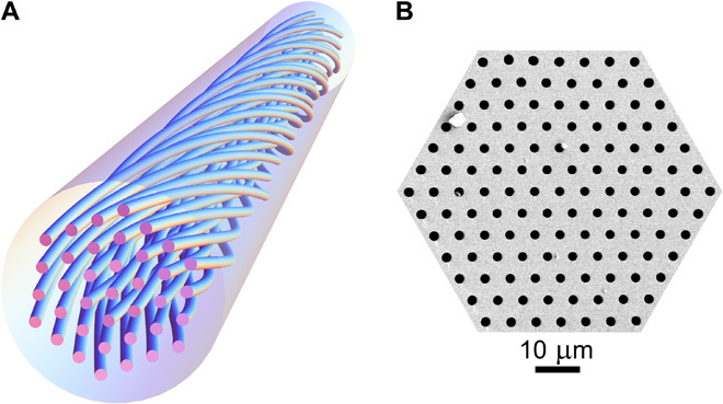
(A) Schematic of a twisted coreless PCF. The axis of rotation coincides with the hollow channel in the center. (B) Scanning electron micrograph of the microstructure.
Chiral fibers with cores have been studied since the 1980s, for example, in connection with circular birefringence (3, 4), current sensing (5, 6), and elimination of higher-order modes in fiber lasers using helical off-axis cores (7, 8). Twisted multicore PCFs have been shown to support helical Bloch waves and to exhibit orbital angular momentum (OAM) birefringence (9). There have also been many theoretical studies, for example, of spin-orbit coupling (10, 11) and Bloch dynamics in helical coupled waveguide arrays (12).
RESULTS AND DISCUSSION
Guidance mechanism
The mechanism underlying this unexpected and intriguing phenomenon can be best understood by first considering the optical Bloch waves in an untwisted coreless PCF. In the fundamental passband (the one with the highest axial refractive index), the field distribution of a Bloch wave (in an infinitely extended periodic cladding) consists of a graphene-like pattern of coupled field lobes trapped between the hollow channels. In the twisted fiber, these lobes are forced to describe helical paths around the fiber axis, which increases their effective axial refractive index in proportion to the square of the radius ρ: Δneff(r) ≈ nSMα2ρ2/2, where α = 2π/L is the twist rate, L is the helical pitch, and nSM is the refractive index of the space-filling mode in the straight fiber.
An essential tool for understanding the characteristics of Bloch waves in periodic structures is the dispersion surface, defined in our case as a 3D plot of axial refractive index neff versus transverse wave vector kT at fixed optical frequency ω. The group velocity of a given Bloch wave, which defines its ray direction, points normal to the dispersion surfaces in the direction of the group velocity dω/dk = ∇kω(k). Cuts through the dispersion surface of the fundamental (highest neff) passband in the two principal crystallographic directions (30° apart) yield the dispersion curves in Fig. 2, numerically calculated from Maxwell’s equations using a full-vectorial plane-wave expansion (the Brillouin zone width for the purple and blue curves is 2π/Λ, where Λ is the interhole spacing; the second cut-through, which exhibits Dirac points, is included to confirm that the shape at the bottom of the passband is paraboloidal). A complete 2D PBG exists for axial refractive indices below the lower passband edge. In the twisted PCF, the dispersion surfaces rise to higher axial refractive indices in proportion to α2ρ2/2 [they also tilt azimuthally by a small angle φ ≈ αρ (not illustrated)]. The figure illustrates how the rays of the Bloch waves (the “Bloch wave rays”) will refract if neff is kept constant at value nm while the radius increases. The small change in tilt angle with radius is ignored for simplicity (this does not strongly affect the argument).
Fig. 2. Cuts through the dispersion surfaces of the highest-index passband in the two principal azimuthal directions (30° apart), numerically calculated at a wavelength of 818 nm for the coreless PCF used in the experiments.
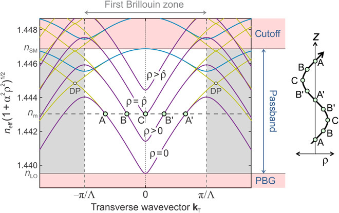
kT is the wave vector component normal to the fiber axis, and Λ is the interhole spacing. The marked Brillouin zone is valid for the purple and blue curves. The dark yellow curves are for the cut-through at 30° to these curves and feature Dirac points (DPs); they are included to show that the shape at the bottom of the passband is approximately paraboloidal. The structure supports a full 2D PBG for axial wave vectors below the bottom of the first passband. On-axis in the twisted PCF (ρ = 0), and everywhere in the untwisted PCF, the passband is as marked, lying between regions of cutoff (neff > nSM) and PBG (neff < nLO). Close to the bottom and top of the passband, the contours of constant neff are very close to perfect circles. As the twist rate α increases, the entire dispersion surface lifts to higher values of index in proportion to α2ρ2 [the diagram will also tilt by an angle φ ≈ αρ (not illustrated)]. For the marked value of modal index nm, light propagates (A → B → C) for radii up to a certain maximum value, , beyond which point nm enters the PBG and the Bloch waves become evanescent. This causes Bloch wave rays to turn around and return to the axis (C → B′ → A′), creating the conditions for bound modes to form at values of nm, satisfying a separate resonance condition. The resulting path in real space is sketched on the right (note that it will be slightly distorted from a perfect sinusoid because the dispersion surface is not exactly a paraboloid).
The fundamental space-filling mode resides at the top of the passband (index nSM), where the curvature is such that, for fixed neff, the Bloch wave rays refract outward with increasing radius; that is, the structure acts as an antiguide. This explains the origins of dips that appear in the transmission spectrum of twisted solid-core PCF (13, 14), caused by phase matching between the core mode and leaky azimuthal resonances (carrying OAM) in the cladding.
In the coreless PCF, however, for a fixed axial refractive index nm, the Bloch wave rays turn parallel to the axis with increasing radius. At a critical value of radius, given by
| (1) |
the bottom of the passband (index nLO) is reached, and the Bloch waves become evanescent, causing them to be reflected back toward the axis. Trapped helical ray paths can thus form, creating the conditions for the formation of bound modes at values of axial wave vector where a transverse resonance exists.
The paths taken by Bloch wave rays in graded photonic crystals can be calculated using Hamiltonian optics, as first explained in 1999 (15). Hamiltonian theory borrows tools from general relativity and has provided the framework for the newer field of “transformation optics” (16). The governing equations take the form
| (2) |
where H(k, x) is the Hamiltonian (the spatially dependent dispersion relation), and x = (x, y, z, −ct) and k = (kx, ky, kz, ω/c) are, respectively, the space-time and wavevector-frequency four-vectors, where ω is the optical frequency, c is the speed of light in vacuum, and t is the time. This equation pair shows that the gradient of the Hamiltonian in reciprocal space changes the position in space-time, whereas the gradient in real space ∇x H alters the position in reciprocal space: real and reciprocal space are thus intertwined. Equation 2 can also be recast in Newtonian form as follows
| (3) |
where [1/m*] is the reciprocal effective mass tensor, and “⊗” denotes a tensor product. The force F is equal to −∇H, that is, the gradient in structural properties. Briefly, the curvature of the dispersion surfaces in reciprocal space creates a photonic effective mass, while the gradient in real space, which is created by the helical twist, creates a force that deflects the photons. Through the principle of least action (Fermat’s principle), the Bloch wave rays follow geodesics in the helically curved space. These geodesics spiral around inside the helically twisted PCF, trapping the light within a topological channel that we might call a “wormhole.” Because Bloch waves have much more complex effective mass tensors than light rays in, for example, curved thin-film waveguides (17), they open up many new opportunities, as seen in the current work.
To illustrate how the Hamiltonian formalism can be applied in this case, we approximate the lower edge of the dispersion surface (Fig. 2) to a paraboloid, permitting H to be written in the form
| (4) |
where A is a constant with the units of length. Substituting H into Eq. 2 and using the approximation α2ρ2 << 1 (valid for our experimental parameters) yields the following equations
| (5) |
which show that σ = (z0 − z) = −ct/nLO and both kz = ωnm/c and ω are constant. They also show that the Bloch wave rays will oscillate harmonically within the potential well formed by the twist
| (6) |
if A > 0, that is, provided the “nose” of the dispersion surface points downward toward lower values of neff (Fig. 2). The general solution of Eq. 6 is
which shows that, depending on the relative phase φ and the value of , the Bloch wave rays will describe sinusoidal, ellipsoidal, or helical paths. Eigenmodes will form at specific values of nm, coinciding with a separate phase-dependent resonance condition, which can be derived using an approach similar to the zigzag model of Kogelnik and Weber (18).
Experimental setup and initial results
The coreless fused-silica PCFs were fabricated using the conventional two-stage stack-and-draw technique. A permanent twist was imposed by spinning the preform during fiber drawing (9). A scanning electron micrograph of the PCF microstructure is shown in Fig. 1. It consists of a regular hexagonal array of hollow channels with a diameter of ~2.2 μm, spaced by ~5.7 μm (air-filling fraction, ~13%). The outer fiber diameter is ~220 μm, and the axis of rotation coincides (within fabrication tolerances) with the center of the middle hollow channel.
To investigate the guidance properties of the twisted PCFs, we launched linearly polarized light from a diode laser at a wavelength of 818 nm into samples (a few tens of centimeters long) with three different twist rates: 1.26, 2.2, and π rad/mm. Launch efficiencies of more than 20% could be readily achieved using a 16× objective lens. A clean near-field modal pattern was observed at the output face of the fibers, imaged using a 30× objective lens and a charge-coupled device (CCD) camera (Fig. 3). Higher twist rates caused the mode field diameter (MFD) to shrink while at the same time increasing the stability of guidance against external perturbations. Figure 3 shows a comparison between the measured mode profiles and those obtained by solving Maxwell’s equations in a helicoidal frame using the full-vectorial finite-element method (14). The agreement is excellent.
Fig. 3. Experimental (upper) and calculated (middle) axial Poynting vector distributions at a wavelength of 818 nm for twist rates 1.26, 2.20, and π rad/mm.
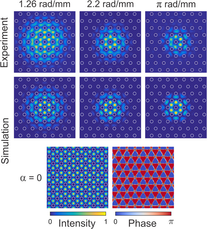
The locations of the hollow channels are marked with white circles. The two lower plots show the calculated axial Poynting vector (left) and phase (right) distributions at the bottom of the passband in the untwisted case, when there is no bound mode.
In the upper panel of Fig. 4A, the calculated modal refractive index and loss are plotted against twist rate for a coreless PCF with six hexagonal layers of hollow channels. The loss reaches a value of ~1.5 dB/m at α = 1.5 rad/mm. Numerically adding more layers of hollow channels reduces the propagation loss without significantly altering the mode pattern, indicating that the solid-glass outer cladding does not play a significant role in the guidance mechanism. The lower panel of the figure compares the measured and calculated effective MFD (MFDeff) (19). The saturation in MFD as α approaches zero is caused by the finite dimensions of the photonic crystal (see the caption of Fig. 4A). It is also intriguing that the MFD falls while the refractive index rises, which is highly unusual behavior for a waveguide.
Fig. 4. Optical properties of the modes guided in twisted coreless PCF.
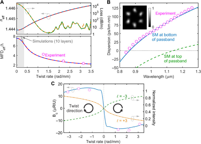
(A) Upper: Calculated refractive indices (left axis) and propagation losses (right axis) for the left circular (LC) (dashed curves) and right circular (RC) (solid curves) polarized modes, plotted against twist rate α. Lower: Measured (data points) and calculated (curves) MFDeff in a coreless PCF with six hexagonal layers of hollow channels (normalized to the interhole spacing Λ), plotted against α at a wavelength of 818 nm. LC (blue dashed line) and RC (red dashed line) polarized modes gave identical results. The saturation in MFDeff at small α (gray-shaded area) is an artifact of the finite size of the photonic crystal. In a 10-layer structure, it saturates at a higher value (dotted gray curve). Note the highly anomalous inverse relationship between MFDeff and refractive index. (B) Experimental (data points) and theoretical (curve) group velocity dispersion of the twist-induced mode, together with the experimental far-field pattern, for α = 1.26 rad/mm. Note that the calculated dispersion of the fundamental space-filling mode (dashed line) is quite different, confirming that the modes form at the bottom of the passband. (C) Experimental (data points) and theoretical (curve) circular birefringence BC as a function of α at 818 nm (left axis). Normalized intensities of the −3 (dashed) and +3 (dash-dotted) harmonics of the mode with OAM order ℓ in the first ring of the fiber as a function of α (right axis).
Optical activity
Because the helical hollow channels force the light to follow a curved path, the twist-induced mode is optically active (20); that is, it has circular birefringence, which is defined by BC = nRC – nLC, where nRC and nLC are the effective refractive indices of the RC and LC polarized modes. The experimental values of BC at 818 nm were measured using the cutback technique for six different twist rates from –π to +π rad/mm. The results are plotted in Fig. 4C, along with the results of numerical modeling (solid blue curve). There is good agreement between the theory and the experiment. The falloff in the magnitude of BC at shorter twist periods is caused by the decreasing mode diameter.
Anomalous cornering
Unlike in conventional step-index fibers, where the guided mode shifts outward away from the bend (“normal cornering”), the twist-guided mode shifts inward toward the bend (“anomalous cornering”) as a result of the downward-pointing lower passband edge (Fig. 5A). Hamiltonian optics shows that there is a pleasing link with centrifugal effects in mechanics, the difference being that, in the twisted coreless PCF, the mode has negative effective mass (caused by the opposite sign of the dispersion surface curvature); thus, it moves in the opposite direction. Related effects have been reported in all-solid bandgap PCFs (21). To explore this, near-field distributions were directly measured at the output face for different bend radii at a wavelength of 703 nm. A PCF with a twist rate of 1.26 rad/mm was used, with its plastic coating removed. The fiber was bent through 180° at a constant radius of curvature R. Just after the bend, the near-field pattern was imaged using a CCD camera and 30× objective lens. The centroid of the light pattern was determined by image processing.
Fig. 5. Anomalous bend-effects in twisted coreless PCF.
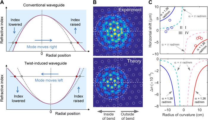
(A) A bend toward the left creates a linear gradient in refractive index, lower on the left and higher on the right of center. Light is cut off from propagating in the blue-shaded areas. Compared to the case of a normal graded index waveguide (upper), the mode shifts anomalously to the inside of the bend in the twist-induced case (lower). (B) Measured (upper) and calculated (lower) axial Poynting vector distribution at a wavelength of 703 nm for a twist rate of α = 1.26 rad/mm and a bend radius of 8.75 cm. The cross hairs mark the center of the fiber, and the circles mark the hollow channels. (C) Upper: Experimental (circles) and theoretical (solid curves) spatial shift of the mode field profile at 703 nm versus bending radius for the twisted PCF with α = 1.26 rad/mm. The theoretical shift (dashed curves) for α = π rad/mm is included for comparison. Lower: Difference in phase indices between straight and bent fiber plotted against radius of curvature for α = 1.26 and π rad/mm. The optical path length decreases as the curvature increases.
Measurements were made for eight different radii (±7.5, ±8.75, ±10, and ±11.25 cm) without changing the sample or recleaving the end-face. The modal patterns in bent twisted PCF were calculated numerically by combining finite-element modeling in the helicoidal frame with conformal mapping techniques (22). Experimental and theoretical near-field Poynting vector distributions show good qualitative agreement (Fig. 5B). The shift of the modal centroid, plotted in Fig. 5C for experiment and theory, confirms that the mode pattern does move anomalously toward the inner side of the bend. The mode is more resistant to these bend-related effects at higher twist rates (dashed curves). In a step-index fiber, the results would lie in quadrants I and III. Because the mode shifts toward the inner side of the bend, its effective path length decreases; that is, its effective index falls (lower panel of Fig. 5C).
CONCLUSIONS
A coreless PCF can be induced to robustly guide light if it is continuously twisted along its length, forming a helical structure. The effect is a consequence of helically twisting the uniform periodic array of hollow channels inside the fiber. This creates spiraling geodesics that trap rays of light (given by the local group velocity of the photonic Bloch waves) without need for any core structure. The effective area of these highly unusual modes decreases with the twist rate; thus, by varying α along the fiber (perhaps by postprocessing), it would be possible to create fibers whose MFD changes radically with propagation distance. This would be of interest in sensing: One could, for example, simply reduce the twist rate to close to zero at the sensing location to allow the modal field to extend out to the edge of the cladding. This effect could also be used for delivery of high-power laser light: During transmission, the mode area could be kept large by a low twist rate and then focused to a smaller mode area close to the end by increasing the twist rate. Another interesting feature is the combination of a large mode area with anomalous dispersion (difficult to achieve in conventional fibers), suggesting applications in nonlinear optics, for example, fundamental solitons with peak powers much higher than are conventionally possible. The ability of twisted fibers to provide OAM (9) and circular birefringence (23) suggests that yet more possibilities may emerge from this unique and unexpected guidance mechanism.
MATERIALS AND METHODS
The uniaxial bending of the fiber was taken into account in finite-element modeling by transforming the refractive index profile n(x, y) to an equivalent refractive index profile neq(x, y) (22) given by
| (7) |
where R is the radius of curvature. The stress-optical effect caused by the local strain of the fiber in the curved region was also included by replacing R with an effective radius of curvature Reff = 1.40R (24). The transverse refractive index profile in the model was rotated to match the end-face of the fiber in the bending experiments.
Acknowledgments
We thank G. Ahmed and F. Babic for providing technical support during fiber fabrication. Funding: The work was funded by the Max-Planck-Gesellschaft (the Max Planck Society). Author contributions: R.B. and G.K.L.W. made the optical measurements, carried out the finite-element modeling, and wrote the paper. R.B., G.K.L.W., M.H.F., and X.M.X. fabricated the twisted PCFs in the fiber-pulling tower. X.M.X. assisted with the optical measurements. P.St.J.R. conceived the experiments, developed the analytical theory, and wrote the paper. Competing interests: The authors declare that they have no competing interests. X.M.X. is now with the College of Optoelectronic Science and Engineering, National University of Defense Technology, Changsha 410073, China. Data and materials availability: All data needed to evaluate the conclusions in the paper are present in the paper. Additional data related to this paper may be requested from the authors.
REFERENCES AND NOTES
- 1.Colladon D., Sur les réflexions d'un rayon de lumière l‘intérieur d’une veine liquide parabolique. C. R. 15, 800–802 (1842). [Google Scholar]
- 2.Kompfner R., The traveling-wave tube as amplifier at microwaves. Proc. IRE 35, 124–127 (1947). [Google Scholar]
- 3.Fujii Y., Hussey C. D., Design considerations for circularly form-birefringent optical fibers. IEE Proc. J. 133, 249–255 (1986). [Google Scholar]
- 4.Argyros A., Pla J., Ladouceur F., Poladian L., Circular and elliptical birefringence in spun microstructured optical fibres. Opt. Express 17, 15983–15990 (2009). [DOI] [PubMed] [Google Scholar]
- 5.Laming R. I., Payne D. N., Electric-current sensors employing spun highly birefringent optical fibers. J. Lightwave Technol. 7, 2084–2094 (1989). [Google Scholar]
- 6.Beravat R., Wong G. K. L., Xi X. M., Frosz M. H., Russell P. St.J., Current sensing using circularly birefringent twisted solid-core photonic crystal fiber. Opt. Lett. 41, 1672–1675 (2016). [DOI] [PubMed] [Google Scholar]
- 7.Wang P., Cooper L. J., Sahu J. K., Clarkson W. A., Efficient single-mode operation of a cladding-pumped ytterbium-doped helical-core fiber laser. Opt. Lett. 31, 226–228 (2006). [DOI] [PubMed] [Google Scholar]
- 8.Ma X., Zhu C., Hu I.-N., Kaplan A., Galvanauskas A., Single-mode chirally-coupled-core fibers with larger than 50μm diameter cores. Opt. Express 22, 9206–9219 (2014). [DOI] [PubMed] [Google Scholar]
- 9.Xi X. M., Wong G. K. L., Frosz M. H., Babic F., Ahmed G., Jiang X., Euser T. G., Russell P. St.J., Orbital-angular-momentum-preserving helical Bloch modes in twisted photonic crystal fiber. Optica 1, 165–169 (2014). [Google Scholar]
- 10.Alexeyev C. N., Alexeyev A. N., Lapin B. P., Milione G., Yavorsky M. A., Spin-orbit-interaction-induced generation of optical vortices in multihelicoidal fibers. Phys. Rev. A 88, 063814 (2013). [Google Scholar]
- 11.Barshak E. V., Alexeyev C. N., Lapin B. P., Yavorsky M. A., Twisted anisotropic fibers for robust orbital-angular-momentum-based information transmission. Phys. Rev. A 91, 033833 (2015). [Google Scholar]
- 12.Longhi S., Bloch dynamics of light waves in helical optical waveguide arrays. Phys. Rev. B 76, 195119 (2007). [Google Scholar]
- 13.Oh S., Lee K. R., Paek U.-C., Chung Y., Fabrication of helical long-period fiber gratings by use of a CO2 laser. Opt. Lett. 29, 1464–1466 (2004). [DOI] [PubMed] [Google Scholar]
- 14.Wong G. K. L., Kang M. S., Lee H. W., Biancalana F., Conti C., Weiss T., Russell P. St.J., Excitation of orbital angular momentum resonances in helically twisted photonic crystal fiber. Science 337, 446–449 (2012). [DOI] [PubMed] [Google Scholar]
- 15.Russell P. St.J., Birks T. A., Hamiltonian optics of nonuniform photonic crystals. J. Lightwave Technol. 17, 1982–1988 (1999). [Google Scholar]
- 16.Schurig D., Pendry J. B., Smith D. R., Transformation-designed optical elements. Opt. Express 15, 14772–14782 (2007). [DOI] [PubMed] [Google Scholar]
- 17.Schultheiss V. H., Batz S., Peschel U., Hanbury Brown and Twiss measurements in curved space. Nat. Photonics 10, 106–110 (2015). [Google Scholar]
- 18.Kogelnik H., Weber H. P., Rays, stored energy, and power flow in dielectric waveguides. J. Opt. Soc. Am. 64, 174–185 (1974). [Google Scholar]
- 19.Mortensen N. A., Effective area of photonic crystal fibers. Opt. Express 10, 341–348 (2002). [DOI] [PubMed] [Google Scholar]
- 20.Bliokh K. Y., Niv A., Kleiner V., Hasman E., Geometrodynamics of spinning light. Nat. Photonics 2, 748–753 (2008). [Google Scholar]
- 21.Birks T. A., Luan F., Pearce G. J., Wang A., Knight J. C., Bird D. M., Bend loss in all-solid bandgap fibres. Opt. Express 14, 5688–5698 (2006). [DOI] [PubMed] [Google Scholar]
- 22.Heiblum M., Harris J., Analysis of curved optical waveguides by conformal transformation. IEEE J. Quantum Electron. 11, 75–83 (1975). [Google Scholar]
- 23.Xi X. M., Weiss T., Wong G. K. L., Biancalana F., Barnett S. M., Padgett M. J., Russell P. St.J., Optical activity in twisted solid-core photonic crystal fibers. Phys. Rev. Lett. 110, 143903 (2013). [DOI] [PubMed] [Google Scholar]
- 24.Schulze C., Lorenz A., Flamm D., Hartung A., Schröter S., Bartelt H., Duparré M., Mode resolved bend loss in few-mode optical fibers. Opt. Express 21, 3170–3181 (2013). [DOI] [PubMed] [Google Scholar]


