Abstract.
Image registration for internal organs and soft tissues is considered extremely challenging due to organ shifts and tissue deformation caused by patients’ movements such as respiration and repositioning. In our previous work, we proposed a fast registration method for deformable tissues with small rotations. We extend our method to deformable registration of soft tissues with large displacements. We analyzed the deformation field of the liver by decomposing the deformation into shift, rotation, and pure deformation components and concluded that in many clinical cases, the liver deformation contains large rotations and small deformations. This analysis justified the use of linear elastic theory in our image registration method. We also proposed a region-based neuro-fuzzy transformation model to seamlessly stitch together local affine and local rigid models in different regions. We have performed the experiments on a liver MRI image set and showed the effectiveness of the proposed registration method. We have also compared the performance of the proposed method with the previous method on tissues with large rotations and showed that the proposed method outperformed the previous method when dealing with the combination of pure deformation and large rotations. Validation results show that we can achieve a target registration error of and an average centerline distance error of . The proposed technique has the potential to significantly improve registration capabilities and the quality of intraoperative image guidance. To the best of our knowledge, this is the first time that the complex displacement of the liver is explicitly separated into local pure deformation and rigid motion.
Keywords: deformable registration, polar decomposition, strain energy, physics model, neuro-fuzzy, vessel registration
1. Introduction
Soft organs such as the liver and the lungs can undergo large organ shifts and tissue deformations in many medical procedures due to patient repositioning, respiration, surgical manipulation, or other physiological reasons such as differences in bowel and stomach volume and weight loss.1–5 Accurate deformable image registration is needed to compensate for the deformation of these soft tissues.1,4,6–8 Although much work has been done in the field of deformable registration, it is still very challenging to efficiently achieve accurate deformable image registration of abdominal organs due to large organ shift and tissue deformation. Effective deformable registration techniques should be fast, accurate, physically consistent, topology preservation, and robust.
Many research works studied deformable image registration for clinical applications. Ahn and Kim9 performed soft tissue experiments on porcine livers to measure the surface deformation and force response of soft tissues. The authors showed that the surface deformation prediction with the soft tissue modeling may not match with the real deformation in large deformation cases. Rohlfing et al.7 used three-dimensional (3-D) MR image sets of four volunteers. It was shown that much of the liver motion is cranial–caudal translation, so the rigid transformation captures much of the motion. However, there is still substantial residual deformation not accounted for by simple rigid-body motion, nearly 20 mm at one place in the liver of one volunteer. Noorda et al.8 presented a subject-specific four-dimensional liver motion model that is created based on registration of dynamically acquired magnetic resonance image data. Several deformation ranges for different directions are addressed; for example, the authors pointed out that the most significant component of liver motion is translation in the feet–head direction.
Both accuracy and speed are important factors that need to be considered in deformable image registration. Until recently, the majority of research on deformable registration of soft tissues required a time-consuming process.4,8,10 For example, the finite-element method (FEM) provides a plausible image registration based on biomechanical models.11 However, in addition to the challenge of accurately determining the boundary conditions for the complex shape of the organs and/or complex interaction forces between the region of interest (ROI) and surrounding tissues, which is required by FEM, FEM suffers from the problem of slow convergence. In the case of liver surgery, Lange et al.12 reported that registration accuracy in the range of 3 mm with a manual interaction time of about 10 min is reasonable for clinical application. During radiotherapy treatment, it is highly desirable to achieve an image registration accuracy of better than 3 mm at the treatment target.13 Noorda et al.8 reported that with an average vessel misalignment of 3 mm, each intensity-based 3-D MRI to two-dimensional (2-D) MRI image registration took , whereas 2-D MRI to 2-D MRI registration took 45 s. Based on these studies, to effectively make full use of the complementary images, the registration error between images of the liver should be controlled to be and the registration time depends on the requirements of a specific clinical application.
To satisfy and improve on these requirements, avoid local minima, and guarantee physical consistency, in our previous work,1 we proposed a fast analytical solution to the deformable registration problem of the liver constrained by 3-D curves and minimal strain energy. The advantages of our method include physically consistent alignment, analytical solution, and topology preservation. This technique is based on the minimal strain energy principle in linear elastic theory and is valid for deformation with only small rotations. While small deformation with small rotations can be approximated by a linear elastic model, images of soft organs with large rotations pose a challenge to this approximation, since the traditional linear elastic theory cannot effectively deal with the deformation involving large rotations as evidenced in liver resection procedures.3 This is because in strain calculation, the high-order derivatives of the displacement field cannot be ignored in the case of large rotations. On the other hand, deformation with large rotations is a problem that is often encountered in the clinical setting. For example, to accurately localize the tumor for liver stereotactic body radiation therapy,6 a deformable image registration method was proposed to align the abdominal-compressed planning CT image to diagnostic MR images. The authors noticed that there is a large difference in liver shape between the CT image taken at the planning stage and the diagnostic MR images, which is mainly caused by abdominal compression, a procedure performed to reduce tumor motion induced by breathing. In this paper, we will specifically address the deformable image registration with large rotation/motion.
Deformation patterns are an important research problem since a good understanding of the deformation patterns can help us to choose a suitable registration method for deformable tissue registration. However, there are few works in the literature to address and analyze the deformation pattern of the abdominal organs. Heizmann et al.3 observed that, for 11 patients who underwent liver resection procedures, there is a significant shape discrepancy or deformation between the livers before the surgery and during the surgery, which is caused by natural mobility, flexibility, and surgical manipulation for resection. A solely rigid alignment of the preoperative and intraoperative images of the whole liver results in a large misalignment of anatomical positions by several centimeters due to varying tissue deformation patterns in different regions of the liver. However, the local deformation of the segmental structure of the liver can be depicted by smooth variation of the displacements, and after a local rigid alignment of the local anatomical structure, the residual discrepancy (i.e., pure deformation) is reduced to . Therefore, based on the above results, the overall large displacement of the liver during liver resection can be modeled as different large rigid local motions plus relatively small local deformations in different regions of the liver. In this paper, we will analyze the deformation pattern of the liver and use the acquired knowledge of the pattern to formulate our registration method. We observed that although surgeries often involve large displacements, in many scenarios, large rotations with small deformation are a valid deformation model. For example, the displacement due to breathing or positioning can be modeled locally as large motion with small deformation. Moreover, in the nonsurgical applications such as diagnosis or follow-up and in minimal invasive or noninvasive procedures such as radiotherapy and high intensity focused ultrasound ablation,6 the assumption of large rotation with small deformation is often valid.
In this study, we extend our previous fast registration technique1 to align deformable images involving large motion of soft tissues using a region-based neuro-fuzzy transformation model. In this study, in each region, a rigid transformation represents the local rigid motion while an affine transformation models the local deformation of soft tissues. As a result, we derive an analytical global optimal solution to the deformable registration problem by minimizing tissue strain energy constrained by 3-D curves and point marks. The proposed method is fast and can overcome the local minima problem. Minimization of strain energy provides the resulting smooth deformation field and good generalization properties, prevents the issue of unnatural deformation, and leads to a physically consistent deformable match of the images. We have validated our proposed technique with MR image data of human subjects. We have demonstrated the effectiveness of our deformable technique in registering MR liver images. This technique has the potential to significantly improve the registration capability and the outcomes of clinical procedures. The contributions of this paper are three fold. First, we analyzed the deformation field of the liver and proposed locally decomposing the total displacement into large rotations and relatively small deformations, so the assumption of a linear elastic model is valid. Second, region-based neuro-fuzzy transformation models for large rotations are proposed to seamlessly piece together the local transformation models involving large rotations. Finally, we extended our method to deformable registration with large rotations for the liver to guarantee the analytic globally optimal solution.
2. Analysis of Deformation Field of the Liver
Linear elastic theory is the best known and most widely used branch of solid mechanics due to its simplicity,11 and linear elastic theory-based image registration can achieve a physically consistent solution that leads to a fast analytical solution to deformable registration.1 The use of linear elastic theory requires that the deformable material is subject to small deformation and small rotation. However, in many clinical applications, the overall displacement of soft tissues, which may be caused by the breathing motion or patient positioning, is large. For example, many clinical procedures require the registration of multimodality images involving ultrasound images such as MR-to-ultrasound registration and CT-to-ultrasound registration. During these procedures, the patient is often repositioned to obtain high-quality ultrasound images, and, as a result, we need to register two images involving large rotations or motion. In this study, we will analyze the deformation patterns of different regions of the liver and investigate whether the linear elastic theory can be employed for the rapid deformable registration of liver images. The comprehensive analysis of deformation patterns will also provide guidelines for proper selection of regions and their parameters in region-based deformable registration. In particular, we will first analyze the deformation patterns of the liver of the human subjects and then use polar decomposition to separate the displacement of the liver into pure deformation and rigid motion. As a result, we justify that the real-large displacement of the liver can be locally decomposed into relatively small pure deformation and large rigid motion.
In this paper, we partition the liver into finite regions. The main advantage of this division is to create multiple region-based submodels to represent the local motion and the local deformation for each region individually. Then, we combine the transformations of the submodels to form a unified transformation model of the entire liver using the neuro-fuzzy technique, which will be discussed in details in Sec. 3.1.
To effectively analyze the deformation patterns of soft tissues, in this section, we propose a technique to decompose overall displacements of soft tissues into rigid motion (rotation and translation/shift) and pure deformation (scaling and shearing) region-by-region. To the best of our knowledge, this is the first time that the complex displacement of the liver is explicitly separated into local pure deformation and rigid motion. This separation also provides deep understanding of the characteristics of the complex motion and deformation of the liver. The procedure to analyze the deformation patterns of the liver is as follows.
-
Step 1:
For each region, we employ an affine transformation to depict displacements in the neighborhood of a selected vessel bifurcation point, where is a matrix, is the translation vector, is the vector of coordinates before transformation, and is the vector of transformed coordinates after affine transformation. Note that the origin of the coordinate system is located at the center of the region.
-
Step 2:We employ a polar decomposition technique to decompose the affine matrix into two components: a rotation matrix and a stretching matrix ,14 i.e.,
(1)
In this study, we employ the singular value decomposition (Ref. 15) to perform the polar decomposition (Ref. 14) as follows:
| (2) |
| (3) |
where , , , , , are all matrices, is a diagonal matrix with positive diagonal elements for real deformation, and and are the orthogonal matrices. Furthermore, this decomposition also gives the principal scaling magnitudes represented by the diagonal elements of in the three orthogonal directions, which are defined by the three columns of . Note that the rotation transformation does not produce any deformation of soft tissues. However, the component represents the stretches of the soft tissues along a set of orthogonal axes. Therefore, the stretching matrix represents the pure deformation of soft tissues in the ROI, which contributes to the elastic potential energy stored in the soft tissues.
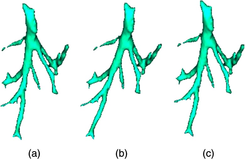
Figure 1 shows the schematic of the decomposition of the deformation transformation to a rotation and a stretching transformation.
Fig. 1.
Schematic of how to decompose the deformable image. (a) Original sample vessel centerline, (b) scale image, and (c) the deformable transformation produced by applying scaling and shearing.
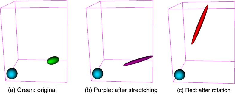
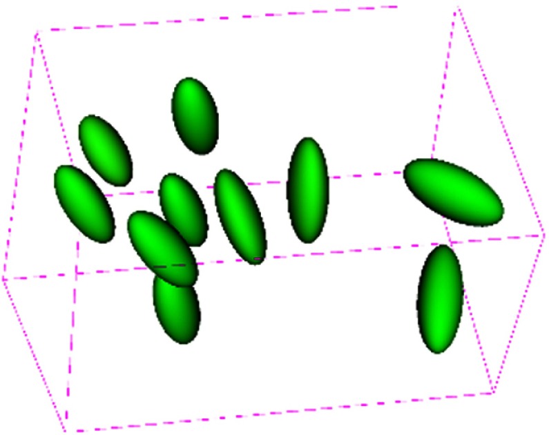
Figure 2 shows the typical decomposition of a deformed ellipsoid object into pure stretching deformation and pure rotation. The green ellipsoid represents a part of soft tissues in the ROI under deformation, the purple ellipsoid stands for the deformed one after pure deformation (i.e., stretching in this study) consisting of scaling and shearing, its long axis represents the principal stretching direction, and its short axes stand for the directions that are compressed. The red ellipsoid is obtained by applying a pure rotation to the deformed purple one. Figure 3 shows the deformation patterns within selected regions of the liver. We observe that the principal stretching orientations in different regions are different, and most regions deform in similar orientations.
Fig. 2.
The typical decomposition of a deformed ellipsoid object into pure stretching deformation and pure rotation. The blue ball is a reference, the green ellipsoid represents a part of soft tissues in the ROI under deformation, the purple ellipsoid stands for the deformed one after pure deformation/stretching consisting of scaling and shearing, its long axis represents the principal stretching direction, and its short axes stand for the directions that are compressed. The red ellipsoid is obtained by rotation from the deformed purple one. (a) Green: original, (b) purple: after strectching, and (c) red: after rotation.
Fig. 3.
Deformation patterns within selected regions of the liver. For each region, a sphere is placed at the region center before deformation. Then, each sphere is transformed by the corresponding local affine transformation to obtain the ellipsoid shown after deformation. The individual magnitude and orientation of both stretching and rotation for each region.
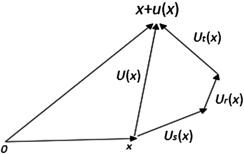
Now, we demonstrate the decomposition of total displacements of the liver due to patient repositioning or respiratory motion in Fig. 4. The total displacement of soft tissues at point within a region is decomposed into three parts: pure deformation (i.e., stretching) , rotation , and translation (i.e., shift) . In the affine transformation of a region , where is the translation, stands for the linear transformation, which can be further decomposed into two parts: pure deformation and pure rotation by using polar decomposition.
Fig. 4.
Displacement decomposition, .
Figure 4 shows a schematic diagram for calculating different components of the overall displacement vector at a point.
2.1. Observations and Analysis
In this study, we employed two typical scenarios to demonstrate the deformation pattern results for the liver. The following procedure is used to obtain displacement components. We first employed our proposed approach (see Sec. 3 for details) to do deformable registration of two images, and we, therefore, obtain the displacement field in the whole ROI. Second, for each region, we obtain 1000 sample points of the displacement field and perform affine registration. Next, we perform polar decomposition to separate the resulting local affine transformation into stretching, rotation, and translation components. The sample displacement points are then employed to calculate the corresponding displacement components with each decomposed transformation component. Table 1 shows the decomposition of displacements for two typical scenarios (see Sec. 4 for the details of MR images used for this experiment). stands for the total average displacement of regions, represents the pure deformation, is the displacement caused by the rotation component, and stands for the displacement from shift. Rotation angle is the local rotation in the angle-axis form converted from rotation matrix , and s1, s2, s3 stand for the scales of pure deformation along three principal axes. The first scenario (denoted as DS1) is the deformation between the two images of the liver acquired at different positions with breath-hold; the second scenario (denoted as DS2) is the deformation between the two images of the liver acquired at the end of inhalation and the end of exhalation. For the first scenario, we have the following observations. First, the average displacement caused by pure deformation is , and the average of maximal scaling is 9.3%. Next, the average displacement caused by pure rotation is , and the average rotation angle is 101.85 deg. Finally, the average displacement caused by shift is . Therefore, tissue shift dominates the overall displacements in each region. We observe the similar deformation patterns in the second scenario. In summary, the pure deformations are small; therefore, the assumptions of linear elastic theory are satisfied in each region. This justifies that we can apply the linear elastic theory to develop our deformable registration algorithm.
Table 1.
Deformation patterns of 10 different regions.
| Displacement (mm) | Rotation | Stretching | ||||||
|---|---|---|---|---|---|---|---|---|
| (deg) | s1 | s2 | s3 | |||||
| DS1 | Deformation between lateral decubitus position and supine position | |||||||
| DS2 | Deformation between end of inhale and end of exhale | |||||||
Note: , total displacement; , from pure deformation; , from rotation; , from shift.
s1, s2, s3 stand for the scales along three principal axes, respectively.
3. Deformable Image Registration for Large Rotations
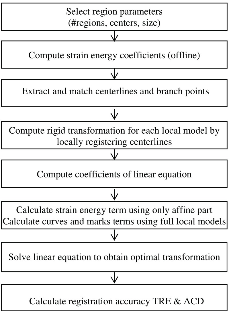
In deformable image registration, in general, no closed-form solutions exist to find the optimal registration parameters due to nonlinear and nonconvex registration energy functions. Furthermore, the optimization methods often get trapped in a local minimum if the starting point is not close to the correct registration. To address the challenge of deformable image registration for soft tissue deformation involving large motion, we propose using a multiple-region-based model to separately represent local motion and local deformation (see Fig. 5). Specifically, a region-based neuro-fuzzy transformation model is proposed to depict the displacement field in the ROI that is partitioned into regions. For each region, a local transformation is proposed to model the corresponding two components: pure deformation is modeled by an affine transformation, and large rigid motion is represented by a local rigid transformation. This local model is a global function, which has good generalization within the region, and its effect range can be effectively localized by selecting the appropriate membership functions of the fuzzy set associated with the region, and the neuro-fuzzy inference system ensures the smooth transition across the regions. By the proper design of registration components, we derive an analytical global optimal solution to the deformable registration involving large motions. The combination of the region-based neuro-fuzzy transformation model and minimizing strain energy leads to a physically consistent and analytical solution to deformable registration.
Fig. 5.
The flowchart of the proposed method.
In this paper, we optimize a physics-based composite energy function. Our registration technique is based on elastic solid mechanics and the minimum strain energy principle. We aim to minimize the following energy function:
| (4) |
where is the overall deformable transformation model, is the strain energy produced by deformation of soft tissues, is the distance energy between pairs of 3-D vessel centerlines extracted from the fixed and moving images, is the distance energy between corresponding point marks such as bifurcation points, and is the weight relative importance of each term. This energy function measures the quality of alignment between two sets of blood vessels, the alignment between two sets of point marks, and the strain energy produced by soft tissue deformation. We discuss different registration components in detail in the following sections.
3.1. Region-Based Neuro-Fuzzy Transformation Model Involving Large Rotation
The nonrigid transformation model is a key component in the deformable image registration, which determines the computational complexity of the image registration process and the capability to depict the real deformation of soft tissues. In this study, we extend a region-based neuro-fuzzy transformation model proposed in our previous work1 to model the deformation of soft tissues involving large rotation and shift. This model consists of two parts: multiple different local models for different regions and a neuro-fuzzy system that is used to seamlessly and smoothly integrate multiple local models into a unified deformable transformation model.16 Based on the characteristics of deformation in each region, we can select a different local model that best depicts the local deformation of that region.
In this study, for each region , the following transformation is employed to depict the local deformation with large motion (i.e., rotation and translate):
| (5) |
| (6) |
where
and
is the rotation center for both the rigid and affine transformations in region . is a fixed rigid transformation for the local rigid motion part, and is the centered affine transformation that mainly depicts the deformation part caused by scaling and shearing and possibly including residual small motion that is not modeled by in region . Since rigid motion does not cause any deformation of soft tissues, it will not produce any strain energy. Therefore, only the affine part is taken into account when the strain energy term in the registration energy function is calculated. This local transformation model is mathematically equivalent to the small deformation represented by followed by a large motion of . In this study, we can still use linear elastic solid theory17 to locally calculate the strain energy in each region, which avoids the inaccuracy caused by a large rotation in the strain energy calculation. The overall transformation of the entire ROI should be represented in a single coordinate system. In this section, centered rigid and centered affine transformation are used to represent the local displacement for each region since it is more intuitive to represent rotation, scaling, and shearing relative to the center of each region.
To facilitate the derivation of an analytical solution to our deformable registration problem [Eq. (4)], we need to rewrite the local transformation as an explicit linear function of transformation parameters. We define the local transformation parameters as follows:
| (7) |
| (8) |
where is the corresponding 12 parameters of and , i.e., the variables to be optimized during image registration, and is the corresponding 12 parameters of the local rigid transformation , which are determined locally before deformable registration.
Therefore, we rewrite Eq. (5) as follows:
| (9) |
where
From Eq. (9), we clearly see that is a linear function of local transformation parameters .
3.1.1. Computation of the local rigid transformation for each region
To obtain the local rigid transformation in region , we minimize a weighted square distance error between corresponding centerlines within the neighborhood of each region center as follows:
| (10) |
where are the region center, are the constants to control the point weight in the region, are the resampled equidistant points on the ’th centerline, that is, for each matched pair of fixed and moving centerlines, the same number of points are resampled with equidistance. In this case, when the points of centerlines are far away from the region center, the corresponding weights will decrease, that is, the distant centerline points have less effect on the resulting rigid transformation. Therefore, the resulting rigid transformation reflects the dominant local rotation and translation of the soft tissues. Note that we do not need a very accurate local rigid transformation because the residual rigid transformation errors that include small rotations and translations can be further addressed by the affine term. According to the linear elastic theory, the affine term is employed to achieve an accurate registration under the condition of small rotations by minimizing the stain energy.
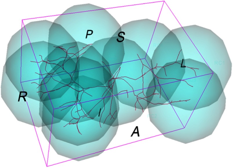
Based on the analysis of deformation patterns of the ROI, we partition the whole ROI into multiple regions, as shown in Fig. 6, each having a different local transformation model . Since the real deformation of the ROI within the organ is smooth in the applications under consideration, a neuro-fuzzy system is employed to seamlessly integrate multiple local models into a unified deformable transformation model to ensure smooth transition across the different regions.16 Our neuro-fuzzy system has the following rules:
where is a 3-D point in the fixed image space, is the corresponding transformed point, is the local transformation model specifically tailored to region .
Fig. 6.
Configuration of local regions.
The overall deformable transformation within the entire ROI can be derived as in Ref. 16
| (11) |
| (12) |
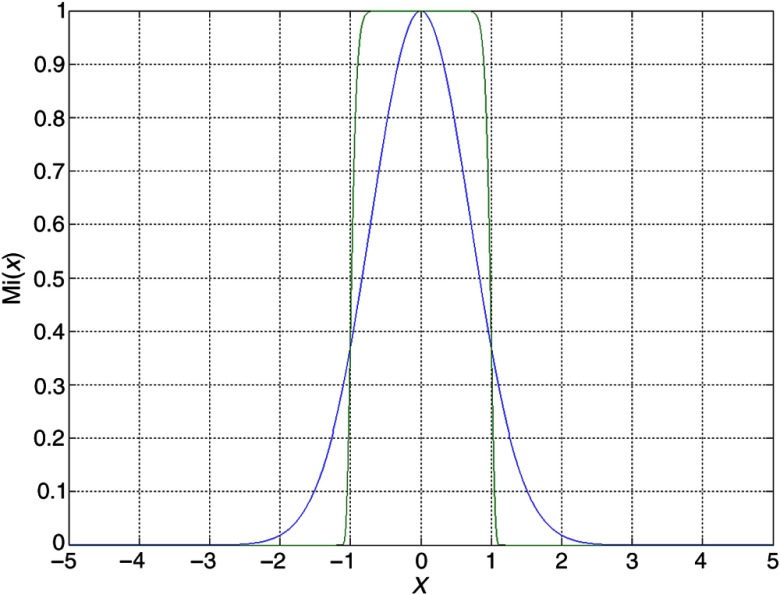
where is the membership function of a fuzzy set associated with region . In this study, the generalized Gaussian membership function (see Fig. 7) is chosen for each local region, are the region center, and and are used to control the effective range of the local model ; large will effectively limit the local model within the range of .
Fig. 7.
One-dimensional generalized Gaussian function ().
Using Eq. (9), we can rewrite the overall transformation (11) for the entire ROI in the following form:
| (13) |
where
| (14) |
is the adjustable parameters in the overall transformation model , including all the parameters of local affine transformations. Note that the is a nonlinear transformation with respect to spatial coordinates but is linear with respect to transformation parameters . Combined with the constraints of 3-D curves, point marks, and strain energy, this linearity of parameters leads to a fast analytical optimal solution.
Furthermore, we can easily calculate the derivative of with respect to the parameters as follows:
| (15) |
Analytical optimal solution to registration energy function
In this section, we briefly define each term in the registration energy function [Eq. (4)] and provide the equations for their derivatives with respect to the transformation parameters . The derivation is similar to our previous work.1
Strain energy
The strain energy term prevents issues such as overfitting and leads to physically consistent deformable match results. Based on elastic solid mechanics, strain energy is generated only by the deformation of soft tissues and can be calculated using the Saint–Venant model,11 as follows:
| (16) |
where is the strain energy density, is a strain tensor, and is the tissue elastic parameters. Note that the strain energy is calculated using only the affine part of the overall transformation .
We can rewrite the strain energy as a quadratic function of the transformation parameters in the following equation (see Appendix for details):
| (17) |
where constants can be calculated offline in advance based on the preprocedural image.
Curve energy
We have proposed an efficient technique to analytically calculate the closest point on a 3-D curve to a given point and the derivative of the distance between curves with respect to transformation parameters through a parametric representation of 3-D curves.1 We aim to minimize the distance between pairs of corresponding vessel centerlines, which is formulated by minimizing the following function:
| (18) |
where is the total number of vessel centerlines, is the number of discrete points on the ’th centerline from the fixed image, , , is the ’th point on the ’th centerline from the fixed image, and is the parametric representation of the ’th vessel centerline in the moving image.1 Its derivative is as follows:
| (19) |
where
Note that is a linear function of transformation parameters , which implies that the curve energy is a quadratic function of parameters .
Point mark energy
Point marks are employed to anchor the deformation at some specific 3-D locations. We assume that there are pairs of corresponding point marks (i.e., bifurcation points) , . Then, we minimize the distance between corresponding point marks by adding the following term to the registration energy function:
| (20) |
Its derivative with respect to the transformation parameters can be analytically calculated through the following equation:
| (21) |
From the above derivation, all three terms are quadratic functions of the transformation parameters . Therefore, the global optimal transformation parameters can be calculated analytically by solving linear equations . This solution is globally optimal, and there are no local minima in this registration energy function.
Registration accuracy measures
To evaluate the quality of our proposed registration approach, we adopt the following three accuracy measures to assess the registration accuracy.
-
1.
Landmark-based target registration errors (TRE): In this assessment, landmarks (targets) were defined as bifurcation points of blood vessels and were localized in both MR image spaces. The resulting registration transformation was applied to transform the landmarks in the fixed image space to the moving image space, TREs were then calculated in the same coordinate system. The TRE is defined as the root mean square (rms) of the distances between the landmarks in the moving MR image and the corresponding homologous landmarks in the fixed MR image after registration.18,19 After vessel centerlines were extracted, bifurcation points were calculated as the intersections of the centerlines using custom software; bifurcation correction was then performed to obtain more consistent homologous bifurcation points across different MR images.
-
2.
Average vessel centerline distance: Since major bifurcation points are only reliably identified in the central part of the liver, blood vessel centerlines cover a larger region of the liver and are employed to assess registration error, i.e., the average centerline distance (ACD) between two corresponding centerlines after registration. In this study, the centerlines were extracted using slicer vascular modeling toolkit (VMTK) centerline extraction modules.20
-
3.Average vessel centerline distance of independent points (ACDIP): When the ACD is computed, the discrete points ’s on the ’th centerline in the fixed image are used for registration. To calculate the ACDIP, we employ a different set of discrete points ’s resampled on the centerlines of the fixed images. These points are independent of ’s and are not utilized for registration. Therefore, the ACDIP is calculated as follows:
where ’s are the discrete points on centerline in the fixed image, is the closest point on the ’th centerline in the moving image from the transformed point , and is the resulting registration transformation. This metric is used to assess the alignment accuracy of centerline parts that are not used for registration.(22)
4. Experimental Results
In this section, we present registration results of liver MR images using our proposed deformable registration method. The images used in this study were acquired from the same human volunteer with a breath-hold. High-quality MR images were acquired in the axial plane using a 1.5T General Electric (GE) scanner (GE Medical Systems, Milwaukee, Wisconsin). Image acquisition was performed using the LAVA gradient echo sequence with , , a flip angle of 12 deg, an image matrix size of , in-plane pixel size of , and slice thickness of 1.5 mm. One pair of image sets was acquired at both the supine position and the lateral decubitus position, in which large rotation occurs. The second pair of image sets was acquired at the end of inhalation and the end of exhalation of the respiratory cycle, which depict the largest displacement during the whole respiratory cycle. Both pairs of MR images were employed for analyzing deformation patterns, as shown in Table 1 of Sec. 2. Since the rotation angle is relatively small in the second pair of MR images, only the first pair of MR images was used to demonstrate our deformable image registration method involving large rotation in this section.
4.1. Visual Inspection
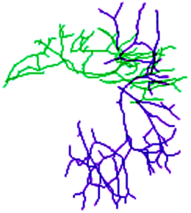
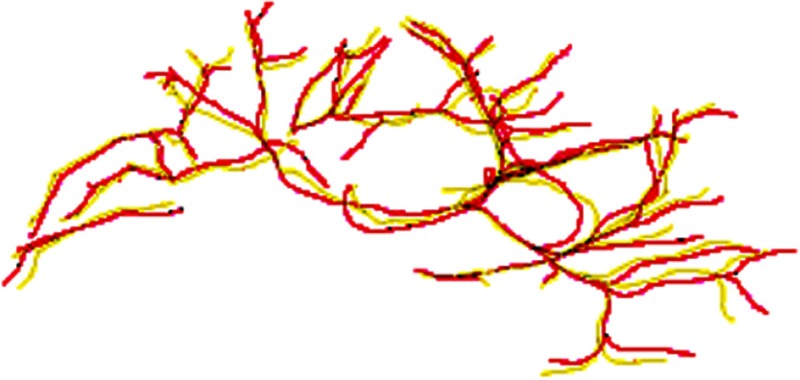
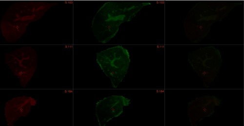
Before deformable registration, Fig. 8 shows soft tissue deformation involving large rotation between two sets of the centerlines at different patient positions. The selected overlays of the centerlines after registration are shown in Fig. 9 using 10 submodels, which demonstrate that the centerlines are matched well after registration. Figure 10 shows the registered images.
Fig. 8.
Centerlines before match. Green lines: lateral decubitus, purple lines: supine position.
Fig. 9.
Overlay of centerlines after match. Red lines: left lateral decubitus, yellow lines: supine centerlines mapped to lateral decubitus.
Fig. 10.
Overlay of images after registration. First column: three orthogonal slices of 3-D MR fixed image, second column: three orthogonal slices of resampled 3-D MR moving image after registration, third column: overlay of two images. Note that the overlay of bright green and bright red vessels is yellow, and internal vessels are correctly matched after registration.
4.2. Registration Accuracy: TRE, ACD, and ACDIP
To quantitatively evaluate the registration accuracy, we considered three accuracy metrics: TRE, ACD, and ACDIP. The resulting average TRE of 56 bifurcation points was , the average ACD of 109 vessel branches was , and the ACDIP was . These registration accuracy measures demonstrate that the proposed deformable registration technique is able to accurately register two sets of deformable images involving large rotations at different regions. The average registration time was about 1 s on a computer with a Core 2 Quad 2.6 GHz Intel CPU and a memory of 4 GB.
4.3. Comparison with the Conventional NFS Method Without Using Large Rotation Formulation
In this section, we compare the proposed method designed for large rotation with the conventional NFS method.1 The results are shown in Table 2. From these results, we observe that the proposed method outperforms the conventional NFS method for all evaluation criteria.
Table 2.
Comparison of registration accuracy (mm).
| Method | TRE () | ACD () | ACDIP () |
|---|---|---|---|
| Proposed NFS | |||
| Conventional NFS | |||
| Rigid registration |
The results can be explained as follows: if the soft tissues undergo small deformation and large rotation, the assumption of linear elastic theory becomes invalid. Since the conventional NFS method is based on the linear elastic theory, the registration using the conventional NFS method naturally results in a relatively large alignment error. However, for the proposed method, it first utilizes an additional local rigid motion model to correct the large motions between the two images, and the residual discrepancy can be accurately represented by the linear elastic theory. As a result, the registration can achieve an accurate alignment.
5. Discussion
5.1. Nonhomogeneous Tissue Property
In this study, we assume the liver tissue is homogeneous; however, this is not a valid assumption in some situations. For instance, the tissue with embedded tumor is in nature inhomogeneous since the stiffness of the tumor is very different from the normal surrounding tissues. Since cancer is the leading cause of death in Canada and is responsible for 30% of all deaths,21 it is important to investigate deformable registration methods that are suitable for inhomogeneous tissues. In the future, we plan to extend our fast deformable registration method to inhomogeneous tissues and investigate the accuracy and speed of the method.
5.2. Optimal Region Partition for Region-Based Neuro-Fuzzy Transformation Models
In this study, we selected 10 regions based on our experience. In the future, we can use some optimization methods such as genetic algorithm to obtain an optimal partition of the ROI into multiple regions. Intuitively, the selection of regions will affect the accuracy and speed of our deformable registration method. We will need to answer the questions such as “what is the optimal number of regions?,” “what is the optimal configuration of locations?,” and “what are the optimal sizes of regions?.”
5.3. Development of New Evaluation Methods
It is very challenging to quantitatively evaluate the registration accuracy of deformable registration techniques in clinical practice due to limited natural marks and complex deformation patterns of soft tissues. To accurately assess the accuracy, the real entire deformation field is required; however, this is usually not available for real human subjects in clinical environments. In the future, we will create and use realistic synthetic data with the known ground truth to thoroughly evaluate our proposed registration method, in addition to the metrics (TRE/ACD). In the future, we will use a biomechanically based FEM to create gold standard deformation fields and completely evaluate the overall performance of our proposed nonrigid registration method. Different from TRE and ACD, which are only based on the sparse information available, the evaluation method will be able to evaluate the registration accuracy not only in the neighborhood of bifurcation points and blood vessels but also in the regions between the landmarks and vessels.
6. Conclusion
We have presented a solution to the deformable registration of MR images of soft tissues with large displacements, especially large rotations. The proposed method can achieve a fast analytical globally optimal solution. It is an extension of our previous work and tackles one type of deformable registration problem, which is typically encountered in many interventional procedures on internal soft organs and tissues in which the large displacements can be modeled as large motion and relatively small local deformation in each region. A neuro-fuzzy transformation model has also been proposed to adapt the previous formulation to the registration problem with large motion to achieve a fast, analytical solution.
This analytical solution to the registration problem can be employed to rapidly match internal structures of soft organs. It can be also used to dynamically update guidance vessel models for vessel extraction in our joint registration and segmentation framework.
In the future, we will investigate the effects of different MR contrasts in our deformable registration. We also plan to extend our techniques to multimodality image registration such as MR-CT registration and MR-US registration.
Acknowledgments
The authors would like to thank Dr. James Drake, Thomas Looi, and other members at CIGITI in the Hospital for Sick Children for the valuable assistance and support. We would also like to thank the Natural Sciences and Engineering Research Council of Canada (NSERC) for the financial support.
Biographies
Xishi Huang is a senior scientist at Istuary Innovation Group. His main areas of interest are image processing, computer vision, deep learning, machine learning, neural networks, neuro-fuzzy, and intelligent techniques.
Jing Ren received her MASc degree and PhD from Western University in 2003 and 2005, respectively. She is currently an associate professor in the Faculty of Engineering and Applied Science at University of Ontario Institute of Technology. She has published more than 50 journal papers and conference papers in the fields of robotics, image processing, and automotive technologies. She received the University Faculty Award in 2006 for her pioneer work in medical simulations using haptics.
Anwar Abdalbari received his MCS degree from Brock University in 2011 and his PhD in image processing from the University of Ontario Institute of Technology in 2016. Currently, he is a sessional professor in the Faculty of Engineering and Applied Science at University of Ontario Institute of Technology. His main areas of research are image processing, soft computing, and automotive technologies.
Mark Green is a professor of computer science and associate dean of science at the University of Ontario Institute of Technology. His main research interests are in the areas of computer graphics, mobile computing, and medical imaging. He is the founder of the ACM UIST series of conferences, is on the steering committee for ACM VRST, and has been on the editorial board of several international journals.
Appendix: Computation of Strain Energy
In this section, we derive the equation to calculate strain energy density . First, we rewrite Eq. (16) as follows:
| (23) |
To compute the element of the strain tensor , we need to compute the derivative of the transformation .
Using Eq. (14), we rewrite the overall neuro-fuzzy transformation model [Eq. (11)] as follows:
| (24) |
The partial derivative of the ’th component of with respect to the ’th coordinate of point is
| (25) |
Denoting , we have
| (26) |
| (27) |
Since is a linear function with respect to transformation parameters , we write Eq. (27) in the following form:
| (28) |
Therefore, we have
| (29) |
Substituting Eq. (29) to Eq. (23), we obtain
Note that is linear with respect to from Eq. (28), and is a quadratic function of and can be rewritten as follows:
Disclosures
The authors declare no conflicts of interest in relation to the work in this article. The human image data used in this paper have been approved by the Research Ethics Board of University of Ontario Institute of Technology.
References
- 1.Huang X., et al. , “3D curve constrained deformable registration using a neuro-fuzzy transformation model,” in Proc. of the 34th Annual Int. Conf. of the IEEE Engineering in Medicine and Biology Society (EMBC ‘12), San Diego, California, pp. 5294–5297 (2012). 10.1109/EMBC.2012.6347189 [DOI] [PubMed] [Google Scholar]
- 2.Jolesz F. A., “MRI-guided focused ultrasound surgery,” Annu. Rev. Med. 60, 417–430 (2009). 10.1146/annurev.med.60.041707.170303 [DOI] [PMC free article] [PubMed] [Google Scholar]
- 3.Heizmann O., et al. , “Assessment of intraoperative liver deformation during hepatic resection: prospective clinical study,” World J. Surg. 34(8), 1887–1893 (2010). 10.1007/s00268-010-0561-x [DOI] [PubMed] [Google Scholar]
- 4.Holden M., “A review of geometric transformations for nonrigid body registration,” IEEE Trans. Med. Imaging 27(1), 111–128 (2008). 10.1109/TMI.2007.904691 [DOI] [PubMed] [Google Scholar]
- 5.VásquezOsorio M., et al. , “Accurate CT/MR vessel-guided nonrigid registration of largely deformed livers,” Med. Phys. 39(5), 2463–2477 (2012). 10.1118/1.3701779 [DOI] [PubMed] [Google Scholar]
- 6.Sotiras A., Davatzikos C., Paragios N., “Deformable medical image registration: a survey,” IEEE Trans. Med. Imaging 32(7), 1153–1190 (2013). 10.1109/TMI.2013.2265603 [DOI] [PMC free article] [PubMed] [Google Scholar]
- 7.Rohlfing T., et al. , “Modeling liver motion and deformation during the respiratory cycle using intensity-based free-form registration of gated MR images,” Proc. SPIE 4319, 337–348 (2001). 10.1117/12.428073 [DOI] [PubMed] [Google Scholar]
- 8.Noorda Y. H., et al. , “Subject-specific four-dimensional liver motion modeling based on registration of dynamic MRI,” J. Med. Imag. 3(1), 015002 (2016). 10.1117/1.JMI.3.1.015002 [DOI] [PMC free article] [PubMed] [Google Scholar]
- 9.Ahn B., Kim J., “Measurement and characterization of soft tissue behavior with surface deformation and force response under large deformations,” Med. Image Anal. 14(2), 138–148 (2010). 10.1016/j.media.2009.10.006 [DOI] [PubMed] [Google Scholar]
- 10.Murphy K, et al. , “Evaluation of registration methods on thoracic CT: the EMPIRE10 challenge,” IEEE Trans. Med. Imaging 30, 1901–1920 (2011). 10.1109/TMI.2011.2158349 [DOI] [PubMed] [Google Scholar]
- 11.Ciarlet P. G., Mathematical Elasticity, Vol. 1, North-Holland Publisher Co., Amsterdam: (1988). [Google Scholar]
- 12.Lange T, et al. , “Vessel-based non-rigid registration of MR/CT and 3D ultrasound for navigation in liver surgery,” Comput. Aided Surg. 8(5), 228–240 (2003). 10.3109/10929080309146058 [DOI] [PubMed] [Google Scholar]
- 13.Shusharina N., Sharp G., “Analytic regularization for landmark-based image registration,” Phys. Med. Biol. 57, 1477–1498 (2012). 10.1088/0031-9155/57/6/1477 [DOI] [PMC free article] [PubMed] [Google Scholar]
- 14.Higham N., “Computing the polar decomposition—with applications,” SIAM J. Sci. Stat. Comput. 7(4), 1160–1174 (1986). 10.1137/0907079 [DOI] [Google Scholar]
- 15.Golub G. H., Van Loan C. F., Matrix Computations, 2nd ed., Johns Hopkins University Press, Baltimore, Maryland: (1989). [Google Scholar]
- 16.Huang X., et al. , “A soft computing framework for software effort estimation,” Soft Comput. 10, 170–177 (2006). 10.1007/s00500-004-0442-z [DOI] [Google Scholar]
- 17.Bower A. F., Applied Mechanics of Solids, CRC Press, Boca Raton, Florida: (2009). [Google Scholar]
- 18.Moghari M. H., Ma B., Abolmaesumi P., “A theoretical comparison of different target registration error estimators,” Medical Image Computing and Computer-Assisted Intervention (MICCAI ‘08), pp. 1032–1040 (2008). [DOI] [PubMed] [Google Scholar]
- 19.Maurer C. R., McCrory J. J., Fitzpatrick J. M., “Estimation of accuracy in localizing externally attached markers in multimodal volume head images,” Proc. SPIE 1898, 43–54 (1993). 10.1117/12.154535 [DOI] [Google Scholar]
- 20.VMTK, http://www.vmtk.org/, “3D slicer,” http://www.slicer.org (28 June 2016).
- 21.Canadian Cancer Society, “Cancer statistics at a glance,”http:// www.cancer.ca/en/cancer-information/cancer-101/cancer-statistics-ata-glance/?region=on (3 August 2014).


