Abstract
Decomposition of transition‐metal amidinates [M{MeC(NiPr)2}n] [M(AMD)n; M=MnII, FeII, CoII, NiII, n=2; CuI, n=1) induced by microwave heating in the ionic liquids (ILs) 1‐butyl‐3‐methylimidazolium tetrafluoroborate ([BMIm][BF4]), 1‐butyl‐3‐methylimidazolium hexafluorophosphate ([BMIm][PF6]), 1‐butyl‐3‐methylimidazolium trifluoromethanesulfonate (triflate) ([BMIm][TfO]), and 1‐butyl‐3‐methylimidazolium tosylate ([BMIm][Tos]) or in propylene carbonate (PC) gives transition‐metal nanoparticles (M‐NPs) in non‐fluorous media (e.g. [BMIm][Tos] and PC) or metal fluoride nanoparticles (MF2‐NPs) for M=Mn, Fe, and Co in [BMIm][BF4]. FeF2‐NPs can be prepared upon Fe(AMD)2 decomposition in [BMIm][BF4], [BMIm][PF6], and [BMIm][TfO]. The nanoparticles are stable in the absence of capping ligands (surfactants) for more than 6 weeks. The crystalline phases of the metal or metal fluoride synthesized in [BMIm][BF4] were identified by powder X‐ray diffraction (PXRD) to exclusively Ni‐ and Cu‐NPs or to solely MF2‐NPs for M=Mn, Fe, and Co. The size and size dispersion of the nanoparticles were determined by transmission electron microscopy (TEM) to an average diameter of 2(±2) to 14(±4) nm for the M‐NPs, except for the Cu‐NPs in PC, which were 51(±8) nm. The MF2‐NPs from [BMIm][BF4] were 15(±4) to 65(±18) nm. The average diameter from TEM is in fair agreement with the size evaluated from PXRD with the Scherrer equation. The characterization was complemented by energy‐dispersive X‐ray spectroscopy (EDX). Electrochemical investigations of the CoF2‐NPs as cathode materials for lithium‐ion batteries were simply evaluated by galvanostatic charge/discharge profiles, and the results indicated that the reversible capacity of the CoF2‐NPs was much lower than the theoretical value, which may have originated from the complex conversion reaction mechanism and residue on the surface of the nanoparticles.
Keywords: amidinates, fluorine, ionic liquids, microwave chemistry, nanoparticles
1. Introduction
Soft wet‐chemical synthesis in organic solvents from metal–organic complexes is an important method to obtain metal or metal alloy nanoparticles.1, 2, 3, 4 Metal amidinates are important precursors for metal nanoparticles5, 6 for thin metal films from low‐pressure chemical vapor deposition (CVD) and atomic layer deposition (ALD).7, 8
Herein, we report the use of metal amidinates [M{MeC‐ (NiPr)2}n] of manganese, iron, cobalt, nickel, and copper as precursors for the synthesis of nanomaterials in ionic liquids (ILs) or in propylene carbonate (PC) to yield selectively transition‐metal nanoparticles (M0‐NPs) or metal fluoride nanoparticles (MF2‐NPs) as stable colloids (Scheme 1). Depending on the used IL (fluorous or non‐fluorous) and the used metal amidinates, we obtained phase‐pure metal M0‐ or MF2‐NPs.
Scheme 1.
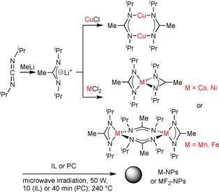
Synthesis and structural formula of the metal amidinates [M{MeC(NiPr)2}n], [M(AMD)n] and their microwave‐assisted thermal decomposition into M‐NPs or MF2‐NPs in IL or PC.
Metal fluoride MFx‐NPs are of significant importance in modern chemistry and materials science, as they are applied, for example, as cathode materials in lithium‐ion batteries in mobile phones, laptops, electric and hybrid vehicles, and other mobile devices.
Modification of lithium transition‐metal electrodes (e.g. oxides, phosphates etc.) is a key issue to improve the performance of lithium‐ion batteries and has therefore been identified as an important aspect of research in this field.9, 10, 11 Assembled batteries based on nanosized materials would result in interesting performance (e.g. short charging time, long lifetime, high capacity).12 Grey et al. showed that the use of FeF2‐NPs instead of macroscopic LiFeF3 led to a significant improvement in performance of the batteries.13 Li et al. presented a straightforward method to synthesize FeF3‐NPs by the decomposition of Fe(NO3)3 ⋅9 H2O in 1‐butyl‐3‐methylimidazolium tetrafluoroborate ([BMIm][BF4]). The [BMIm][BF4] IL was described as a stabilization medium for the NPs and the fluoride source for the FeF3‐NPs.14 Pinna, Kemnitz, and co‐workers and Wickleder and co‐workers independently also reported the simple syntheses of MFx‐NPs from metal salts in conventional solutions. In contrast to our work, they used diethylene glycol and methanol as the solvents and HF in methanol solution and ammonium fluoride as the fluorine sources. Similar to this work, the MFx‐NPs were obtained under microwave heating.15, 16
1.1. ILs and PC as Nonconventional Solvents in Nanoparticle Synthesis
For the synthesis of the NPs, we used the 1‐butyl‐3‐methylimidazolium tetrafluoroborate ([BMIm][BF4]) and 1‐butyl‐3‐methylimidazolium tosylate ([BMIm][Tos]) ILs or the organic carbonate propylene carbonate (PC). For the Fe‐containing NPs, [BMIm] ILs with [PF6]− and [TfO]− anions (Scheme 2) were also considered.
Scheme 2.
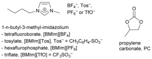
Liquid media used here for NP synthesis and stabilization.
ILs are alternatives to aqueous and organic solvents17, 18 and are regarded as a new liquid medium19, 20 for the preparation of inorganic materials, including M‐NPs.21, 22, 23, 24, 25, 26, 27, 28, 29 ILs have negligible vapor pressure, high thermal stability, high ionic conductivity, a broad liquid‐state temperature range, and the ability to dissolve a variety of materials.30, 31 M‐NPs in ILs have been prepared from metal salts reduced by H2 32, 33, 34 or without a reductant,35 from organometallic metal complexes,36 including metal carbonyls,37 through thermal or photochemical38 decomposition or by electroreduction/electrodeposition.21, 39, 40 The electrostatic and steric properties of the ILs stabilize the M‐NPs without the need for additional capping ligands, surfactants, or polymers.21, 40, 41 PC is an aprotic, highly dipolar solvent with low viscosity,42, 43 low flammability, low volatility, and low toxicity.44 PC also has a large liquid temperature range (m.p. −49 °C, b.p. 243 °C), is considered a “green solvent” of only low (eco)toxicity, and is completely biodegradable.45 There are only a few reports on the synthesis of M‐NPs in organic carbonates.46, 47, 48 Whereas ILs are expensive solvents, organic carbonates, such as PC, are available at low cost.
2. Results and Discussion
2.1. Thermal Decomposition of M‐Amidinates
The transition‐metal amidinates [M{MeC(NiPr)2}n] [M(AMD)n; M=MnII, FeII, CoII, NiII, n=2; CuI, n=1) (Scheme 1) were dissolved/suspended under a nitrogen atmosphere in dried and deoxygenated [BMIm][BF4], [BMIm][PF6], [BMIm][TfO], [BMIm][Tos], or PC. Quantitative decomposition of the metal amidinates was then achieved by microwave heating after only 10 (IL) or 40 min (PC) by using a low power of 50 W to give an approximate temperature of 240 °C in the reaction mixture (Scheme 1).
Dispersions of the NPs in the ILs or PC were reproducibly obtained by this microwave decomposition route. Quantitative decomposition of the metal amidinates by microwave heating was verified by 1H NMR spectroscopy through the disappearance of the signal for the N‐C(CH3)‐N methyl group. Thermogravimetric analysis (TGA) decomposition measurements also showed that the amidinates fully decomposed at temperatures between 120 and 195 °C (Table 1 and Figure S2 in the Supporting Information).49
Table 1.
Thermogravimetric analysis of the metal amidinates.[a]
| Amidinate | Decomposition temperature [°C] | Δm TGA (exptl/calcd) |
|---|---|---|
| Mn(AMD)2 | 120 | 81/74 |
| Fe(AMD)2 | 130 | 83/75 |
| Co(AMD)2 | 180 | 83/78 |
| Ni(AMD)2 | 135 | 83/79 |
| Cu(AMD) | 185 | 69/69 |
[a] See thermogravimetric diagrams in Figure S2.
2.2. NPs from M(AMD)n in [BMIm][BF4]
Microwave‐induced thermal decomposition of the metal amidinates in [BMIm][BF4] gave M0‐ or MF2‐NPs depending on the used M‐amidinates. The resulting NPs were analyzed by transmission electron microscopy (TEM) and powder X‐ray diffraction (PXRD) for their morphology, size, and size dispersion as well as their crystalline phase (MF2‐ or M‐NPs) (Figure 1, 2, 3, 4, 5, 6). Metal/fluorine ratios and oxidation states were determined by energy‐dispersive X‐ray spectroscopy (EDX, by combination with TEM) (Figure 1, 2, 3, 4) and by X‐ray photoelectron spectroscopy (Figure S5). The determined M/F ratios confirmed the formation of MF2 nanoparticles (Table 2).
Figure 1.
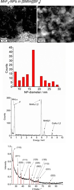
From top to bottom: HAADF‐STEM, particle‐size histogram, EDX and PXRD (MnF2 reference peaks in red from COD 9009076) of 1.0 wt % MnF2‐NPs in [BMIm][BF4] from Mn(AMD)2.
Figure 2.

From top to bottom: HAADF‐STEM, particle‐size histogram, EDX, SAED, and PXRD (FeF2 reference peaks in red from COD 9007536) of 1.0 wt % FeF2‐NPs in [BMIm][BF4] from Fe(AMD)2. Space group of FeF2; P42/mnm, tetragonal, rutile structure.
Figure 3.

From top to bottom: HAADF‐STEM, particle‐size histogram, EDX, and PXRD (CoF2 reference peaks in red from COD 9009073) of 1.0 wt % CoF2‐NPs in [BMIm][BF4] from Co(AMD)2. Space group of CoF2: P42/mnm (136), tetragonal, rutile structure.
Figure 4.
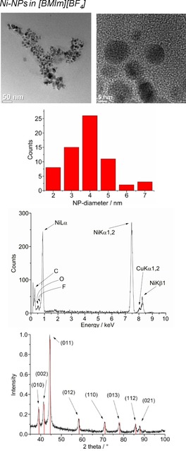
From top to bottom: TEM, particle‐size histogram, EDX, and PXRD (Ni‐hexagonal close packing reference peaks in red from COD 9008509) of 1.0 wt % Ni‐NPs in [BMIm][BF4] from Ni(AMD)2.
Figure 5.
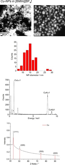
From top to bottom: HAADF‐STEM, particle‐size histogram, EDX, and PXRD (Cu reference peaks in red from COD 9013014) of 1.0 wt % Cu‐NPs in [BMIm][BF4] from Cu(AMD).
Figure 6.
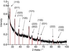
PXRD (FeF2 reference peaks in red from COD 9007536) of 1.0 wt % FeF2‐NPs in [BMIm][PF6] from Fe(AMD)2.
Table 2.
MF2 composition determination in [BMIm][BF4].[a]
| Amidinate | Phase[b] | Molar ratio M/F | |
|---|---|---|---|
| EDX[c] | XPS | ||
| Mn(AMD)2 | MnF2 | 1:1.7 | – |
| Co(AMD)2 | CoF2 | 1:1.8 | 1:2.0[d] |
| Fe(AMD)2 | FeF2 | 1:1.9 | 1:2.0[d] |
[a] 1.0 wt % MFx‐NP/[BMIm][BF4] dispersions obtained by microwave irradiation with 50 W for 10 min at 240 °C; see matching entries for size determinations in Table 3. [b] Precipitated and washed with acetonitrile, reference: Crystallography Open Database (COD). [c] k‐factor Mn: 1.375, k‐factor F: 1.601, k‐factor Fe: 1.403, k‐factor Co: 1.495; estimated minimum errors±1–2 %. [d] See Figure S5.
The crystalline part of the nanoparticle product was identified by PXRD as metal fluoride nanoparticles (MF2‐NPs) for the middle‐transition‐metals Mn, Fe, and Co, whereas only metal nanoparticles (M‐NPs) were found for the late‐transition‐metals Ni and Cu. For FeF2, selected area electron diffraction (SAED) also confirmed the formation of FeF2 (Figure 2). For the MF2‐NPs, the [BF4]− anion in the [BMIm][BF4] IL must be the fluorine source, perhaps in combination with a very small amount (<10 ppm) of residual water. The [BF4]− anion is also known to be temperature labile.50 We are not aware of any other easy or straightforward methods for the synthesis of MnF2, FeF2, or CoF2 nanoparticles. At present, metal difluoride nanoparticles are prepared by reduction of metal trifluoride or alkali‐transition‐metal fluorides.51, 52
High‐angle annular dark‐field scanning transmission electron microscopy (HAADF‐STEM) images (Figure 1, 2, 3) yield particle sizes of 8–29 nm for MnF2, 20–77 nm for CoF2, and 25–98 nm for FeF2 (Figure 1, 2, 3). The average particle sizes are 15±4 nm for MnF2, 43±11 nm for CoF2, and 65±18 nm for FeF2. For the elongated FeF2 particles, a longer dimension was measured. The MF2‐NPs are air stable for several days, as assessed by PXRD, which was measured several days after the synthesis of the NPs and after storing the product in air.
The microwave‐induced decomposition of Ni(AMD)2 and Cu(AMD) in [BMIm][BF4] gives black and deep‐red 1.0 wt % dispersions of elemental Ni‐ and Cu‐NPs. The PXRD patterns present only diffractions for Ni and Cu metal (Figures 5 and 6). Spherical M‐NPs with narrow size distributions are obtained (Table 3). The average diameter for the microwave‐synthesized Ni‐ and Cu‐NPs at 1.0 wt % metal dispersions in [BMIm][BF4] is between 11(±3) and 14(±4) nm, respectively, as observed in previous reports for M‐NPs in this IL.35, 36, 37, 40, 48 The size and size dispersions of the M‐ and MF2‐NPs from [BMIm][BF4] are summarized in Table 3. The M‐ and MF2‐NP sizes agree with the size evaluations from the PXRD patterns by using the Scherrer equation with Scherrer factor k=0.95.53 No extra stabilizers or capping molecules were added to achieve and stabilize these nanoparticle sizes. The M‐NPs dispersions are stable with non‐agglomerated NPs present 6 weeks after the synthesis according to high‐resolution (HR)‐STEM measurements performed at that time (Figures 1, 5, 6).
Table 3.
M/MF2‐NP size and size distribution.[a]
| Precursor | M/MFx‐NPs | TEM Ø (σ) [nm][b] | PXRD Ø (σ) [nm][b,c] |
|---|---|---|---|
| [BMIm][BF4][a] | |||
| Mn(AMD)2 | MnF2 | 15(±4) | 14(±3) |
| Fe(AMD)2 | FeF2 | 65(±18) | 73(±3) |
| Co(AMD)2 | CoF2 | 43(±11) | 47(±5) |
| Ni(AMD)2 | Ni | 11(±3) | 12(±3) |
| Cu(AMD) | Cu | 14(±4) | 17(±3) |
| [BMIm][Tos][a] | |||
|---|---|---|---|
| Mn(AMD)2 | –[d] | – | – |
| Fe(AMD)2 | Fe | 11(±2) | – |
| Co(AMD)2 | Co | 7(±4) | – |
| Ni(AMD)2 | Ni | 12(±4) | 13(±2) |
| Cu(AMD) | –[d] | – | – |
| PC[a] | |||
|---|---|---|---|
| Mn(AMD)2 | Mn | 4(±2) | –[e] |
| Fe(AMD)2 | Fe | 2(±2) | –[e] |
| Co(AMD)2 | Co | 4(±2) | – |
| Ni(AMD)2 | Ni | 8(±5) | 12(±2) |
| Cu(AMD) | Cu | 51(±8) | 55(±7) |
[a] 1.0 wt % M‐NP/[BMIm][BF4], M‐NP/[BMIm][Tos], or M‐NP/PC dispersion obtained by microwave irradiation with 50 W for 10 min (40 min for PC) at 240 °C. [b] Average diameter (Ø) and standard deviation (σ). See the Experimental Section for TEM measurement conditions. [c] From the Scherrer equation, Scherrer‐factor: 0.95.53 [d] No particles were obtainable. [e] No precipitation possible.
The literature describes the synthesis of FeF3 nanoparticles starting by the decomposition of iron(III) nitrate in fluorine‐containing ILs. Maier et al. used metal fluoride nanoparticles as an electrode material in lithium‐ion batteries.10, 14 A direct synthesis of phase‐pure FeF2 nanoparticles, which are also discussed as a promising electrode material for lithium‐ion batteries, has not yet been described.
2.3. FeF2‐NPs from Fe(AMD)2 in [BMIm][PF6] and [BMIm][TfO]
The decomposition of Fe(AMD)2 in the fluorine‐containing [BMIm][PF6] and [BMIm][TfO] ILs also gave phase‐pure and crystalline FeF2 nanoparticles (Figures 6 and 7). The [PF6]− and [TfO]− anions served as fluorine sources for the FeF2‐NPs.
Figure 7.
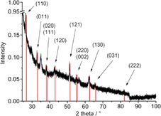
PXRD (FeF2 reference peaks in red from COD 9007536) of 1.0 wt % FeF2‐NPs in [BMIm][TfO] from Fe(AMD)2.
From [BMIm][PF6] and [BMIm][TfO], prismatic FeF2 nanoparticles were synthesized with a typical size distribution of 68 (±14) nm for the former and 72(±12) nm for the latter IL (Figure 8).
Figure 8.

TEM images of 1.0 wt % FeF2‐NPs in [BMIm][TfO].
In contrast to the [BF4]− and [PF6]− anions, the formation of FeF2 nanoparticles in [BMIm][TfO] is surprising because of the thermally stability and expected insensitivity to hydrolytic cleavage of the triflate anion, [CF3SO3]−.54, 55, 56 However, another fluorine source can be excluded according to the low fluorine content in the IL (<50 ppm), which was determined by ion chromatographic analysis.
2.4. NPs from M(AMD)n in [BMIm][Tos]
The non‐fluorous [BMIm][Tos] IL was investigated for comparison to the fluorous [BMIm][BF4] IL. The metal amidinates were dissolved/suspended in [BMIm][Tos] and heated by microwave irradiation up to 240 °C for 10 min.
The microwave‐induced decomposition of the amidinates M(AMD)n with M=Fe, Co, Ni in [BMIm][Tos] gave small M0‐NPs. For M=Mn and Cu, no particles were obtained. The M‐NP/IL dispersions were stable without extra stabilizers or capping molecules with non‐agglomerated NPs present 6 weeks after the synthesis according to the TEM measurements performed at that time. The average diameter of the M‐NPs at 1.0 wt % of M‐NP/[BMIm][Tos] was between 7 and 12 nm, as determined by TEM (Table 3; Figures 9, 10, 11, top). Elemental analysis by EDX spectroscopy (Figure 9, 10, 11, bottom) gave the expected bands for Fe, Co, and Ni.
Figure 9.
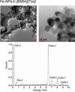
TEM (top) and EDX (bottom) of 1.0 wt % Fe‐NPs in [BMIm][Tos] from Fe(AMD)2.
Figure 10.
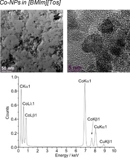
TEM (top) and EDX (bottom) of 1.0 wt % Co‐NPs in [BMIm][Tos] from Co(AMD)2.
Figure 11.
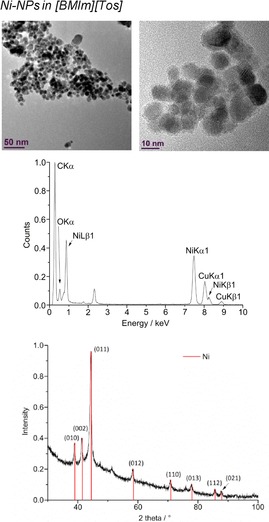
From top to bottom: TEM, EDX, and PXRD (Ni‐hexagonal close packing reference peaks in red from COD 9008509) of 1.0 wt % Ni‐NPs in [BMIm][Tos] from Ni(AMD)2.
2.5. NPs from M(AMD)n in Propylene Carbonate (PC)
The organic solvent PC served as a comparative media for the ionic liquids. The corresponding metal amidinates were dissolved/suspended in PC and heated in the microwave reactor up to 240 °C for 40 min.
The microwave‐induced decomposition of the metal amidinates in PC required a longer time of 40 min to complete in comparison to 10 min in the ILs. After attempting to irradiate Fe‐ and Co(AMD)2 for a short period of 10 min, very small metal clusters were seen in the HR‐TEM images, which agglomerate to bigger particles in the electron beam of the transmission electron microscope (see Figures S3 and S4). After 40 min of microwave irradiation, the synthesis in PC gave very small M0‐NPs, except for Cu. The median diameter for the microwave‐synthesized M‐NPs at 1.0 wt % M‐NPs in PC was between 2 and 8 nm for M=Mn, Fe, Co, and Ni, as determined by HR‐TEM (Figures 12, 13, 14, 15, top; Table 3). The Cu‐NPs were somewhat larger than those seen before (Figure 16).5 Again, no extra stabilizers or capping molecules were needed to achieve and stabilize the NPs, that is, to prevent agglomeration of these particle for up to at least 6 weeks after synthesis. At that time, the non‐agglomerated NPs were still present, as seen by HR‐STEM measurements. Elemental analysis by EDX spectroscopy (Figures 12, 13, 14, 15, bottom) gave the expected bands for Mn, Fe, Co, and Ni. The formation of Fe and Co‐NPs was supported by X‐ray photoelectron spectroscopy (XPS, Figures 10 and 11).57 No oxygen was detected by EDX and no shift from M0 was observed in the X‐ray photoelectron spectra; thus, it can be assumed that elemental cobalt and iron nanoparticles were obtained. We can, of course, not exclude the formation of surface metal oxide or slightly charged metal nanoparticles.
Figure 12.
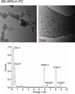
HR‐TEM (top) and EDX (bottom) of 1.0 wt % Mn‐NPs in PC from Mn(AMD)2.
Figure 13.
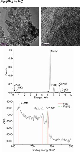
From top to bottom: HR‐TEM, EDX, and XPS (Fe reference in red and Fe3O4 in dashed‐green) of 1.0 wt % Fe‐NPs in PC from Fe(AMD)2.
Figure 14.
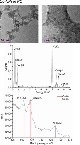
From top to bottom: HR‐TEM, EDX, and XPS (Co reference peaks in red and CoO in dashed‐green) of 1.0 wt % Co‐NPs in PC from Co(AMD)2.
Figure 15.
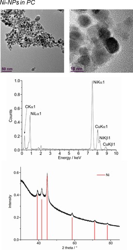
From top to bottom: HR‐TEM, EDX, and PXRD (Ni‐hexagonal close packing reference peaks in red from COD 9008509) of 1.0 wt % Ni‐NPs in PC from Ni(AMD)2.
Figure 16.
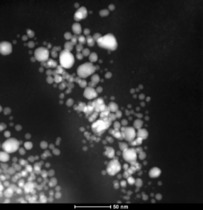
HAADF‐STEM of 1.0 wt % Cu‐NPs in PC from Cu(AMD).
Only the larger Ni‐NPs proved of sufficient crystallinity to afford a PXRD pattern (Figure 12).
2.6. Electrochemical Measurements
The possible electrochemical performance of CoF2 as a cathode material for lithium‐ion batteries was evaluated by the galvanostatic charge/discharge profiles on a half‐cell.
Fluorides as electrode materials for lithium‐ion batteries normally undergo a conversion reaction and deliver higher energy density than the current cathode materials (such as LiCoO2 and LiFePO4). The overall conversion reaction for CoF2 can be described by [Eq. (1)]:
| (1) |
in which E is the potential and C is the specific capacity.
The galvanostatic charge/discharge profiles of the CoF2 nanoparticles from decomposition of Co(AMD)2 in [BMIm][BF4] are presented in Figure 17. The redox plateau at the first discharge is 1.8 V, which is much lower than the theoretical value but comparable to that reported in the literature.58, 59, 60 Two oxidation plateaus in the charge process are in the potential ranges of 3.5 to 4.2 V and 4.2 to 4.8 V, which correspond to the processes of reconverting back into CoxF and CoF2, respectively.58 In the second discharge process, the slope process before the plateau at 1.5 V can be assigned to the reduction of CoxF with lithium ions. It is noticeable that the redox process of CoxF disappears after several cycles, which is one of main reasons for the reduced capacity. If the current density is increased to 20 mA g−1, the charge and discharge plateaus are 4.3 and 1.55 V, respectively. The specific capacity stabilizes at 70 to 80 mAh g−1. However, the specific capacity is much lower than the theoretical value, even at such a low discharge rate, for which the reasons can be concluded to result from the complex conversion mechanism (low reversible capacity), residue functional groups on the surface of the nanoparticles, and so on.
Figure 17.

Galvanostatic charge/discharge profiles of a half‐cell with CoF2‐NPs as the cathode material at different current densities. CoF2‐NPs from decomposition of Co(AMD)2 in [BMIm][BF4].
3. Conclusions
We described herein the simple, reproducible, and broadly applicable microwave‐induced decomposition of metal amidinates for the selective synthesis of small, uniform, and phase‐pure metal fluoride nanoparticles (MF2‐NPs) (M=Mn, Fe, Co) and transition‐metal nanoparticles (M‐NPs) (M=Ni, Cu) in the fluorous 1‐butyl‐3‐methylimidazolium tetrafluoroborate ([BMIm][BF4]) ionic liquid (IL). Fe amidinate was also decomposed in fluorous [BMIm] ILs with hexafluorophosphate ([PF6]) and trifluoromethanesulfonate ([TfO]) anions to FeFe2 nanoparticles. Decomposition in the non‐fluorous [BMIm][Tos] (Tos=tosylate) ionic liquid or in propylene carbonate (PC) yielded M‐NPs. Thus, MF2‐NPs were obtained in fluorous media, that is, in ILs with [BF4]−, [PF6]−, and [TfO]− counterions for M=Mn, Fe, and Co. In non‐fluorous [BMIm][Tos] and PC media as well as for M=Ni and Cu, the metal nanoparticles were obtained from decomposition of the transition‐metal amidinates. The results nicely showed the advantages of the metal–organic precursor concept based on metal amidinates together with unconventional solvents and microwave‐heating assisted pyrolysis.61 No additional surfactants or other reducing agents (e.g. dihydrogen, NaBH4, etc.) were necessary for soft chemical nanomaterial formation. M‐NP dispersions were stable, and nonagglomerated NPs were still present 6 weeks after synthesis according to transmission electron microscopy measurements performed at that time.
Synthesis in [BMIm][Tos] and PC media seemed to yield smaller NPs than in [BMIm][BF4], with the only exception of Cu. Decomposition of metal amidinates in fluorous ILs could provide easy and novel access to metal fluoride nanoparticles as shown by the phase‐pure formation of MF2 for M=Mn, Fe, and Co. The phase purity was based on powder X‐ray diffraction, energy‐dispersive X‐ray spectroscopy, and X‐ray photoelectron spectroscopy analysis of the derived product. CoF2 nanoparticles as a cathode material for lithium‐ion batteries presented a less reversible capacity than the theoretical one, which was believed to be caused by the complex conversion reaction mechanism.
Experimental Section
All synthesis experiments were performed with Schlenk techniques under a nitrogen or argon atmosphere, as the amidinates are hygroscopic and air sensitive. Propylene carbonate (PC) was dried under high vacuum (1.0 Pa) for several days. 1,3‐Diisopropylcarbodiimide (>99 %), manganese(II) chloride (>98 %), iron(II) chloride (>98 %), cobalt(II) chloride (>99 %), nickel(II) chloride (>99 %), copper(I) chloride (>99 %), methyllithium, 1‐chlorobutane (>99 %), and 1‐methylimidazole (>99 %) were obtained from Sigma–Aldrich and were used without further purification; racemic propylene carbonate was obtained from Sigma–Aldrich (purity 99.7 %, H2O free).
The metal amidinates were synthesized by deprotonation and methylation of 1,3‐diisopropylcarbodiimide with methyllithium. The resulting lithium amidinate was treated with metal halides (Scheme 1) according to literature procedures.62, 63
The [BMIm][BF4] and [BMIm][Tos] ionic liquids were synthesized by treating 1‐methylimidazole with 1‐chlorobutane to yield first [BMIm][Cl], which was further treated with HBF4 and sodium tosylate to give [BMIm][BF4] and [BMIm][Tos]. The ILs were dried under high vacuum (0.10 mPA) at 80 °C for several days. Anion exchange was assessed by ion chromatography (Dionex ICS‐1100, with IonPac AS14, 4×250 mm column) to be >99 %. The water content by coulometric Karl Fischer titration (ECH/ANALYTIK JENA AQUA 40.00) was less than 10 ppm.
Thermogravimetric analysis (TGA) was performed with a Netzsch TG 209 F3 Tarsus equipped with an Al crucible by using a heating rate of 10 K min−1 under an inert atmosphere (N2).
X‐ray photoelectron spectroscopy (XPS‐ESCA) measurements were performed with a Fisons/VG Scientific ESCALAB 200X xp‐spectrometer, operating at room temperature, a pressure of 1.0 mPa, and a sample angle of 30°. Spectra were recorded by using polychromatic Al Kα excitation (14 kV, 20 mA) and an emission angle of 0°. Calibration of the spectra was performed by recording spectra with Al Kα X‐rays from clean samples of copper, silver, and gold at 20 and 10 eV pass energies and comparison with reference values.
PXRD data were measured at ambient temperature with a Bruker D2 Phaser by using a flat sample holder and CuKα radiation (λ=1.54182 Å, 35 kV). Samples were precipitated with acetone from the NP/IL and NP/PC dispersion and were washed with acetonitrile. PXRD patterns were measured for 2–12 h. Small shifts in the PXRD patterns are not uncommon for nanoparticles. A number of effects can be considered for such shifts, including range of stoichiometric composition, partly inhomogeneous elemental distribution, defects such as stacking and twin faults, and nanosized crystalline domains being much smaller than the bulk reference material, which cause lattice contraction or expansion and strain.64, 65
NMR spectra were recorded with a Bruker Avance DRX 200 (1H, 200 MHz) and Avance DRX 500 (13C, 125.57 MHz) at 298 K in C6D6, and the chemical shifts are referenced to the solvent peaks against tetramethylsilane.
High‐angle annular dark‐field scanning transmission electron microscopy (HAADF‐STEM) micrographs were taken at room temperature with an FEI Tecnai G2 F20 TEM66 operated at an accelerating voltage of 200 kV. Samples were deposited on 50 μm carbon‐coated gold or copper grids. The size distribution was calculated from a manual diameter determination over a minimum of 60 isolated particles.
TEM‐EDX was performed with an FEI Tecnai G2 F20, 136 eV, and an exposure time for individual EDX spectra of 3 min. EDX analysis always showed trace amounts of oxygen. Preparation on the grids was done in a glove box. However, there was an unavoidable 30 s air contact upon bringing the grid in the TEM chamber before evacuation. A low intensity oxygen signal at 0.52 eV was also always present on noble metal samples and pure carbon grids (from surface oxidation).
In a typical procedure for the synthesis of the metal nanoparticles (M‐NPs), decomposition by microwave heating was performed under a nitrogen atmosphere. The metal amidinate powders (see Table 4) were dissolved/suspended (for ≈12 h) at room temperature in the dried and deoxygenated IL or PC. The mass of the metal amidinates was set for 1.0 wt % M‐NP in IL or PC dispersion. The mixture was placed in a microwave reactor (CEM, Discover) and irradiated for 10 min (IL) or 40 min (PC) at a power of 50 W to an indicated temperature of 240 °C. Each decomposition reaction was performed at least twice.
Table 4.
Mass of the amidinates in 2.0 g [BMIm][BF4], [BMIm][Tos] or PC for ≈1.0 wt % total metal dispersion.
| Precursor[a] | mg [mmol] [M{MeC(NiPr)2}n][b] |
|---|---|
| {Mn(AMD)2}2 | 122.8 (0.18) |
| {Fe(AMD)2}2 | 121.1 (0.18) |
| Co(AMD)2 | 113.3 (0.33) |
| Ni(AMD)2 | 115.9 (0.34) |
| {Cu(AMD)}2 | 64.5 (0.16) |
[a] see Scheme 1 for structural formula. [b] Molar mass of {Mn(AMD)2}2: 674.81 g mol−1; {Fe(AMD)2}2: 676.64 g mol−1; Co(AMD)2: 340.42 g mol−1; Ni(AMD)2: 340.18 g mol−1; {Cu(AMD)}2: 409.56 g mol−1; density [BMIm][BF4]: 1.21 g mL−1, 1 mL, 1.21 g; density PC: 1.19 g mL−1, 1 mL, 1.19 g.
For the electrochemical measurements, the CoF2 nanoparticles were precipitated from the IL dispersion by the addition of dry acetonitrile (10 mL), which was followed by centrifugation, decantation, and redispersing (3×) by supersonic treatment in acetonitrile (10 mL), centrifugation, and finally drying under high vacuum. The electrochemical performance of CoF2 as a cathode material for lithium‐ion batteries was evaluated by galvanostatic charge/discharge profiles on a half‐cell. The working electrode was prepared by coating the slurry composed of 90 wt % CoF2 and 10 wt % PVDF on an aluminum foil. The half‐cell with lithium foil as the counter electrode was assembled in an argon‐filled glove box with [O2] <0.5 ppm and [H2O]<0.5 ppm. The electrolyte was 1 m LiPF6 in ethylene carbonate/dimethyl carbonate (EC/DMC) (50:50 v/v) from Sigma–Aldrich, and Whatmann glass microfiber membranes were used as the separator. The cut‐off potentials were controlled to 1.0 and 4.8 V versus Li+/Li by an electrochemical workstation from Metrohm Autolab PGSTAT 302. LiPF6 can decompose even at room temperature following the path outlined in Equation (2):
| (2) |
Besides, LiPF6 can hydrolyze with moisture to form HF [Eq. (3)]:
| (3) |
However, in commercial electrolytes [1 mol L−1 LiPF6 in EC/DMC (1:1 v/v)], the impurities are negligible (HF content less than 10 ppm), and the decomposition temperature of LiPF6 in such electrolytes is believed to be as high as 80 °C, which is far above the operating temperature of our experiments.67 All operations were performed in a glove box filled with argon with a moisture content less than 0.5 ppm, which prevented hydrolysis of LiPF6 to form LiF and HF. Besides, the electrochemical stability window of such an electrolyte is regarded to be as high as 5.0 V versus Li+/Li due to a passivation reaction, which is much larger than the potential applied in our case. Therefore, LiF may form but should be in a very minor amount.
Supporting information
As a service to our authors and readers, this journal provides supporting information supplied by the authors. Such materials are peer reviewed and may be re‐organized for online delivery, but are not copy‐edited or typeset. Technical support issues arising from supporting information (other than missing files) should be addressed to the authors.
Supplementary
Acknowledgements
The authors are thankful to the Deutsche Forschungsgemeinschaft (DFG) for financial support in the priority project SPP 1708 through grant Ja466/31‐1, PO780/14‐1 and in the Ernst–Ruska–Center core‐facilities program through grant MA 1280/40‐1.
K. Schütte, J. Barthel, M. Endres, M. Siebels, B. M. Smarsly, J. Yue, C. Janiak, ChemistryOpen 2017, 6, 137.
References
- 1. Kim M. R., Xu Z., Chen G., Ma D., Chem. Eur. J. 2014, 20, 11256–11275. [DOI] [PubMed] [Google Scholar]
- 2. Zan X., Bai H., Wang C., Zhao F., Duan H., Chem. Eur. J. 2016, 22, 5204–5210. [DOI] [PMC free article] [PubMed] [Google Scholar]
- 3.
- 3a. Lara P., Wheelaghan O. R., Conejero S., Poteau R., Philippot K., Chaudret B., Angew. Chem. Int. Ed. 2011, 50, 12080–12084; [DOI] [PubMed] [Google Scholar]; Angew. Chem. 2011, 123, 12286–12290; [Google Scholar]
- 3b. Golindano M., del Tibisay C., Martínez M., Susana I., Delgado G., Omayra Z., Rivas R., Guaicaipuro P., Technical Proceedings of the 2005 NSTI Nanotechnology Conference and Trade Show, Vol. 2, CRC Press, Boca Raton, 2005, pp. 634–637; [Google Scholar]
- 3c. Cordente N., Amiens C., Chaudret B., Respaud M., Senocq F., J. Appl. Phys. 2003, 94, 6358–6365; [Google Scholar]
- 3d. Li Y., Liu J., Wang Y., Wang Z. L., Chem. Mater. 2001, 13, 1008–1014. [Google Scholar]
- 4.
- 4a. Cormary B., Dumestre F., Liakakos N., Soulantica K., Chaudret B., Dalton Trans. 2013, 42, 12546–12553; [DOI] [PubMed] [Google Scholar]
- 4b. Kovalenko M. V., Coperet C., Dalton Trans. 2013, 42, 12520; [DOI] [PubMed] [Google Scholar]
- 4c. Metin Ö., Sun X., Sun S., Nanoscale 2013, 5, 910–912; [DOI] [PubMed] [Google Scholar]
- 4d. Kumara C., Dass A., Nanoscale 2012, 4, 4084–4086; [DOI] [PubMed] [Google Scholar]
- 4e. Zhang Z.-C., Hui J.-F., Guo Z.-G., Yu Q.-Y., Xu B., Zhang X., Liu Z.-C., Xu C.-M., Gao J.-S., Wang X., Nanoscale 2012, 4, 2633–2639; [DOI] [PubMed] [Google Scholar]
- 4f. Kumara C., Dass A., Nanoscale 2011, 3, 3064–3067; [DOI] [PubMed] [Google Scholar]
- 4g. Marcos Esteban R., Schütte K., Marquardt D., Barthel J., Beckert F., Mülhaupt R., Janiak C., Nano-Structures Nano-Objects 2015, 2, 28–34. [Google Scholar]
- 5. Schütte K., Meyer H., Gemel C., Barthel J., Fischer R. A., Janiak C., Nanoscale 2014, 6, 3116–3126. [DOI] [PubMed] [Google Scholar]
- 6. Glaria A., Cure J., Piettre K., Coppel Y., Turrin C.-O., Chaudret B., Fau P., Chem. Eur. J. 2015, 21, 1169–1178. [DOI] [PubMed] [Google Scholar]
- 7. Bahlawane N., Kohse-Hoinghaus K., Premkumar P. A., Lenoble D., Chem. Sci. 2012, 3, 929–941. [Google Scholar]
- 8. Krisyuk V., Aloui L., Prud'homme N., Sysoev S., Senocq F., Samelor D., Vahlas C., Electrochem. Solid-State Lett. 2011, 14, D26–D29. [Google Scholar]
- 9. Poizot P., Laruelle S., Grugeon S., Dupont L., Tarascon J.-M., Nature 2000, 407, 496–499. [DOI] [PubMed] [Google Scholar]
- 10. Li C., Gu L., Tsukimoto S., van Aken P. A., Maier J., Adv. Mater. 2010, 22, 3650–3654. [DOI] [PubMed] [Google Scholar]
- 11. Tarascon J.-M., Armand M., Nature 2001, 414, 359–367. [DOI] [PubMed] [Google Scholar]
- 12. Borchard-Tuch C., Chem. Unserer Zeit 2003, 37, 436–437. [Google Scholar]
- 13. Yamakawa N., Jiang M., Key B., Grey C. P., J. Am. Chem. Soc. 2009, 131, 10525–10536. [DOI] [PubMed] [Google Scholar]
- 14. Li C.-N., Gu L., Tong J., Maier J., ACS Nano 2011, 5, 2930–2938. [DOI] [PubMed] [Google Scholar]
- 15.
- 15a. Noack J., Emmerling F., Kirmse H., Kemnitz E., J. Mater. Chem. 2011, 21, 15015–15021; [Google Scholar]
- 15b. Di Carlo L., Conte D. E., Kemnitz E., Pinna N., Chem. Commun. 2014, 50, 460–462. [DOI] [PubMed] [Google Scholar]
- 16. Waltz F., Swider M. A., Hoyer P., Hassel T., Erne M., Möhwald K., Adlung M., Feldhoff A., Wickleder C., Bach F.-W., Behrens P., J. Mater. Sci. 2012, 47, 176–183. [Google Scholar]
- 17. Welton T., Chem. Rev. 1999, 99, 2071–2084. [DOI] [PubMed] [Google Scholar]
- 18.
- 18a. Kuchenbuch A., Giernoth R., ChemistryOpen 2015, 4, 677–681; [DOI] [PMC free article] [PubMed] [Google Scholar]
- 18b.introduction to special issue on ionic liquids in chemical synthesis: Feldmann C., Z. Naturforsch. B 2013, 68, 1057. [Google Scholar]
- 19. Hallett J. P., Welton T., Chem. Rev. 2011, 111, 3508–3576. [DOI] [PubMed] [Google Scholar]
- 20. Torimoto T., Tsuda T., Okazaki K., Kuwabata S., Adv. Mater. 2010, 22, 1196–1221. [DOI] [PubMed] [Google Scholar]
- 21. Janiak C., Z. Naturforsch. B 2013, 68, 1059–1089. [Google Scholar]
- 22. Campbell P. S., Prechtl M. H. G., Santini C. C., Haumesser P.-H., Curr. Org. Chem. 2013, 17, 414–429. [Google Scholar]
- 23. Freudenmann D., Wolf S., Wolff M., Feldmann C., Angew. Chem. Int. Ed. 2011, 50, 11050–11060; [DOI] [PubMed] [Google Scholar]; Angew. Chem. 2011, 123, 11244–11255. [Google Scholar]
- 24.
- 24a. Ahmed E., Breternitz J., Groh M. F., Ruck M., CrystEngComm 2012, 14, 4874–4885; [Google Scholar]
- 24b. Ahmed E., Ruck M., Dalton Trans. 2011, 40, 9347–9357; [DOI] [PubMed] [Google Scholar]
- 24c. Groh M. F., Müller U., Ahmed E., Rothenberger A., Ruck M., Z. Naturforsch. B 2013, 68, 1108–1122. [Google Scholar]
- 25. Morris R. E., Chem. Commun. 2009, 2990–2998. [DOI] [PubMed] [Google Scholar]
- 26. Parnham E. R., Morris R. E., Acc. Chem. Res. 2007, 40, 1005–1013. [DOI] [PubMed] [Google Scholar]
- 27. Cooper E. R., Andrews C. D., Wheatley P. S., Webb P. B., Wormald P., Morris R. E., Nature 2004, 430, 1012–1016. [DOI] [PubMed] [Google Scholar]
- 28. Dupont J., Scholten J. D., Chem. Soc. Rev. 2010, 39, 1780–1804. [DOI] [PubMed] [Google Scholar]
- 29. Klauke K., Hahn B., Schütte K., Barthel J., Janiak C., Nano-Structures Nano-Objects 2015, 1, 24–31. [Google Scholar]
- 30. Lin Y., Dehnen S., Inorg. Chem. 2011, 50, 7913–7915. [DOI] [PubMed] [Google Scholar]
- 31. Lodge P., Science 2008, 321, 50. [DOI] [PubMed] [Google Scholar]
- 32.
- 32a. Fonseca G. S., Machado G., Teixeira S. R., Fecher G. H., Morais J., Alves M. C. M., Dupont J., J. Colloid Interface Sci. 2006, 301, 193–204; [DOI] [PubMed] [Google Scholar]
- 32b. Fonseca G. S., Domingos J. B., Nome F., Dupont J., J. Mol. Catal. A: Chem. 2006, 248, 10–16; [Google Scholar]
- 32c. Fonseca G. S., Umpierre A. P., Fichtner P. F. P., Teixeira S. R., Dupont J., Chem. Eur. J. 2003, 9, 3263–3269; [DOI] [PubMed] [Google Scholar]
- 32d. Dupont J., Fonseca G. S., Umpierre A. P., Fichter P. F. P., Teixeira S. R., J. Am. Chem. Soc. 2002, 124, 4228–4229. [DOI] [PubMed] [Google Scholar]
- 33.
- 33a. Arquillière P., Haumesser P. H., Santini C. C., Microelectron. Eng. 2012, 92, 149–151; [Google Scholar]
- 33b. Silveira E. T., Umpierre A. P., Rossi L. M., Machado G., Morais J., Soares G. V., Baumvol I. J. R., Teixeira S. R., Fichtner P. F. P., Dupont J., Chem. Eur. J. 2004, 10, 3734–3740. [DOI] [PubMed] [Google Scholar]
- 34. Migowski P., Machado G., Teixeira S. R., Alves M. C. M., Morais J., Traverse A., Dupont J., Phys. Chem. Chem. Phys. 2007, 9, 4814–4821. [DOI] [PubMed] [Google Scholar]
- 35.
- 35a. Redel E., Walter M., Thomann R., Hussein L., Krüger M., Janiak C., Chem. Commun. 2010, 46, 1159–1161; [DOI] [PubMed] [Google Scholar]
- 35b. Redel E., Walter M., Thomann R., Vollmer C., Hussein L., Scherer H., Krüger M., Janiak C., Chem. Eur. J. 2009, 15, 10047–10059; [DOI] [PubMed] [Google Scholar]
- 35c. Redel E., Thomann R., Janiak C., Inorg. Chem. 2008, 47, 14–16. [DOI] [PubMed] [Google Scholar]
- 36.
- 36a. Marquardt D., Barthel J., Braun M., Ganter C., Janiak C., CrystEngComm 2012, 14, 7607–7615; [Google Scholar]
- 36b. Salas G., Podgorsek A., Campbell P. S., Santini C. C., Pádua A. A. H., Costa Gomes M. F., Philippot K., Chaudret B., Turmine M., Phys. Chem. Chem. Phys. 2011, 13, 13527–13536; [DOI] [PubMed] [Google Scholar]
- 36c. Gutel T., Garcia-Antón J., Pelzer K., Philippot K., Santini C. C., Chauvin Y., Chaudret B., Basset J.-M., J. Mater. Chem. 2007, 17, 3290–3292. [Google Scholar]
- 37.
- 37a. Vollmer C., Janiak C., Coord. Chem. Rev. 2011, 255, 2039–2057; [Google Scholar]
- 37b. Marcos Esteban R., Schütte K., Brandt P., Marquardt D., Meyer H., Beckert F., Mülhaupt R., Kölling H., Janiak C., Nano-Structures Nano-Objects 2015, 2, 11–18; [Google Scholar]
- 37c. Vollmer C., Schröder M., Thomann Y., Thomann R., Janiak C., Appl. Catal. A 2012, 425–426, 178–183; [Google Scholar]
- 37d. Marquardt D., Vollmer C., Thomann R., Steurer P., Mülhaupt R., Redel E., Janiak C., Carbon 2011, 49, 1326–1332; [Google Scholar]
- 37e. Marquardt D., Xie Z., Taubert A., Thomann R., Janiak C., Dalton Trans. 2011, 40, 8290–8293; [DOI] [PubMed] [Google Scholar]
- 37f. Vollmer C., Redel E., Abu-Shandi K., Thomann R., Manyar H., Hardacre C., Janiak C., Chem. Eur. J. 2010, 16, 3849–3858; [DOI] [PubMed] [Google Scholar]
- 37g. Redel E., Krämer J., Thomann R., Janiak C., J. Organomet. Chem. 2009, 694, 1069–1075; [Google Scholar]
- 37h. Krämer J., Redel E., Thomann R., Janiak C., Organometallics 2008, 27, 1976–1978; [Google Scholar]
- 37i. Redel E., Thomann R., Janiak C., Chem. Commun. 2008, 1789–1791. [DOI] [PubMed] [Google Scholar]
- 38.
- 38a. Zhu J. M., Shen Y. H., Xie A. J., Qiu L. G., Zhang Q., Zhang X. Y., J. Phys. Chem. C 2007, 111, 7629–7633; [Google Scholar]
- 38b. Firestone M. A., Dietz M. L., Seifert S., Trasobares S., Miller D. J., Zaluzec N. J., Small 2005, 1, 754–760. [DOI] [PubMed] [Google Scholar]
- 39. MacFarlane F. Endres. D., Abbott A., Electrodeposition from Ionic Liquids, Wiley-VCH, Weinheim, 2008. [Google Scholar]
- 40. Marquardt D., Janiak C., Nachr. Chem. 2013, 61, 754–757. [Google Scholar]
- 41.
- 41a. Schmid G., Nanoparticles, Wiley-VCH, Weinheim, 2004, pp. 185–238; [Google Scholar]
- 41b. Antonietti M., Kuang D., Smarly B., Zhou Y., Angew. Chem. Int. Ed. 2004, 43, 4988–4922; [DOI] [PubMed] [Google Scholar]; Angew. Chem. 2004, 116, 5096–5100; [Google Scholar]
- 41c. Astruc D., Lu F., Aranzaes J. R., Angew. Chem. Int. Ed. 2005, 44, 7852–7872; [DOI] [PubMed] [Google Scholar]; Angew. Chem. 2005, 117, 8062–8083; [Google Scholar]
- 41d. Kaper H., Endres F., Djerdj I., Antonietti M., Smarsly B. M., Maier J., Hu Y.-S., Small 2007, 3, 1753–1763. [DOI] [PubMed] [Google Scholar]
- 42. Bayardon J., Holz J., Schäffner B., Andrushko V., Verevkin S., Preetz A., Börner A., Angew. Chem. Int. Ed. 2007, 46, 5971–5974; [DOI] [PubMed] [Google Scholar]; Angew. Chem. 2007, 119, 6075–6078. [Google Scholar]
- 43. Verevkin S. P., Emel′yanenko V. N., Toktonov A. V., Chernyak Y., Schäffner B., Börner A., J. Chem. Thermodyn. 2008, 40, 1428–1432. [Google Scholar]
- 44. Schäffner B., Verevkin S. P., Börner A., Chem. Unserer Zeit 2009, 43, 12–21. [Google Scholar]
- 45. Schäffner B., Schäffner F., Verevkin S. P., Börner A., Chem. Rev. 2010, 110, 4554–4581. [DOI] [PubMed] [Google Scholar]
- 46. Vollmer C., Thomann R., Janiak C., Dalton Trans. 2012, 41, 9722–9727. [DOI] [PubMed] [Google Scholar]
- 47.
- 47a. Demel J., Čejka J., Bakardjieva S., Štěpnička P., J. Mol. Catal. A: Chem. 2007, 263, 259–265; [Google Scholar]
- 47b. Reetz M., Lohmer G., Chem. Commun. 1996, 1921–1922; [Google Scholar]
- 47c. Behr A., Döring N., Durowicz-Heil S., Ellenberg B., Kozik C., Lohr C., Schmidke H., Fett Wissenschaft Technologie (Fat Sci. Technol.) 1993, 95, 2–12; [Google Scholar]
- 47d. Behr A., Schmidke H., Chem. Ing. Tech. 1993, 65, 568–569. [Google Scholar]
- 48. Marcos Esteban R., Meyer H., Kim J., Gemel C., Fischer R. A., Janiak C., Eur. J. Inorg. Chem. 2016, 2106–2113. [Google Scholar]
- 49. Coyle J. P., Monillas W. H., Yap G. P. A., Barry S. T., Inorg. Chem. 2008, 47, 683–689. [DOI] [PubMed] [Google Scholar]
- 50. Archer D. G., Widegren J. A., Kirklin D. R., Magee J. W., J. Chem. Eng. Data 2005, 50, 1484–1491. [Google Scholar]
- 51. Mai H.-X., Zhang Y.-W., Si R., Yan Z. G., Sun L.-D., You L. P., Yan C.-H., J. Am. Chem. Soc. 2006, 128, 6426–6436. [DOI] [PubMed] [Google Scholar]
- 52. Li C., Lin J., J. Mater. Chem. 2010, 20, 6831–6847. [Google Scholar]
- 53. Langford J. I., Wilson A. J. C., J. Appl. Crystallogr. 1978, 11, 102–113. [Google Scholar]
- 54.Z. Zhang, R. Reddy, EPD Congress 2002 and Fundamentals of Advanced Materials for Energy Conversion, 2002.
- 55. Kosmulski M., Gustafsson J., Rosenholm J. B., Thermochim. Acta 2004, 412, 47–53. [Google Scholar]
- 56. Ngo H. L., LeCompte K., Hargens L., McEwen A. B., Thermochim. Acta 2000, 357, 97–102. [Google Scholar]
- 57.
- 57a. Battistoni C., Dormann J. L., Fiorani D., Paparazzo E., Viticoli S., Solid State Commun. 1981, 39, 581; [Google Scholar]
- 57b. Shang X.-L., Zhang B., Han E.-H., Ke W., Electrochim. Acta 2012, 65, 294–304. [Google Scholar]
- 58. Teng Y. T., Pramana S. S., Ding J., Wu T., Yazami R., Electrochim. Acta 2013, 107, 301–312. [Google Scholar]
- 59. Reddy M. A., Breitung B., Wall C., Trivedi S., Chakravadhanula V. S. K., Helen M., Fichtner M., Energy Technol. 2016, 4, 201–211. [Google Scholar]
- 60. Wall C., Prakash R., Kübel C., Hahn H., Fichtner M., J. Alloys Compd. 2012, 530, 121–126. [Google Scholar]
- 61.
- 61a. Bilecka I., Niederberger M., Nanoscale 2010, 2, 1358–1374; [DOI] [PubMed] [Google Scholar]
- 61b. Chen W., Gutmann B., Kappe C. O., ChemistryOpen 2012, 1, 39–48; [DOI] [PMC free article] [PubMed] [Google Scholar]
- 61c. Rodríguez A. M., Prieto P., de la Hoz A., Díaz-Ortiz A., Martin R., Garcia J. I., ChemistryOpen 2015, 4, 308–317. [DOI] [PMC free article] [PubMed] [Google Scholar]
- 62. Lim B. S., Rahtu A., Park J.-S., Gordon R. G., Inorg. Chem. 2003, 42, 7951–7958. [DOI] [PubMed] [Google Scholar]
- 63. Schmidt S., Schulz S., Blaeser D., Boese R., Bolte M., Organometallics 2010, 29, 6097–6103. [Google Scholar]
- 64.
- 64a. Makinson J. D., Lee J. S., Magner S. H., De Angelis R. J., Weins W. N., Hieronymus A. S., Adv. X-Ray Anal. 1998, 42, 407–411; [Google Scholar]
- 64b. Zhang F., Chan S.-W., Spanier J. E., Apak E., Jin Q., Robinson R. D., Herman I. P., Appl. Phys. Lett. 2002, 80, 127–129; [Google Scholar]
- 64c. Madhusudan Reddy K., Manorama S. V., Reddy A. R., Mater. Chem. Phys. 2003, 78, 239–245. [Google Scholar]
- 65.
- 65a. Kurian M., Kunjachan C., Nano-Structures Nano-Objects 2015, 1, 15–23; [Google Scholar]
- 65b. Manhas M., Kumar V., Sharma V., Ntwaeaborwa O. M., Swart H. C., Nano-Structures Nano-Objects 2015, 3, 9–16. [Google Scholar]
- 66.Ernst Ruska-Centre for Microscopy and Spectroscopy with Electrons, 2016; FEI Tecnai G2 F20 Journal of large-scale research facilities, 2, A77, https://doi.org/10.17815/jlsrf-2-138.
- 67. Xu K., Chem. Rev. 2004, 104, 4303–4417. [DOI] [PubMed] [Google Scholar]
Associated Data
This section collects any data citations, data availability statements, or supplementary materials included in this article.
Supplementary Materials
As a service to our authors and readers, this journal provides supporting information supplied by the authors. Such materials are peer reviewed and may be re‐organized for online delivery, but are not copy‐edited or typeset. Technical support issues arising from supporting information (other than missing files) should be addressed to the authors.
Supplementary


