Abstract
Recent studies have shown that trading efficiency for improved resolution may be a good choice for small lesion detection, but utilizing collimator with high efficiency may be more favorable for cardiac single photon emission computed tomography (SPECT). This paper investigates the tradeoffs of geometric-blurring compensation for high-resolution (HR) and high-sensitivity (HS) SPECT imaging with various parallel-hole collimators in terms of noise reduction and resolution recovery. Five types of collimators were investigated and compared with a general all purpose collimator using computer simulations. It is shown that less noisy SPECT images can be achieved with unchanged spatial resolution using large collimator holes with blurring compensation. The optimal collimator hole found in the computer simulation is the one with a hole acceptance angle in the range from 6.3° to 9.4°. Phantom experiments with two cardiac-insert phantoms show that the resolution of the image obtained using the HS collimator can be successfully recovered by blurring compensation, and the image is less noisy compared to the one obtained using the HR collimator.
Keywords: Collimator, high-sensitivity (HS), resolution compensation, single photon emission computed tomography (SPECT)
I. Introduction
CURRENT clinical single photon emission computed tomography (SPECT) widely use high-resolution (HR) collimators to gain better image resolution. HR collimators suffer from low sensitivity which leads to a noisy image, which may not be favorable for all types of SPECT studies [1]. Recent studies on collimator utilizations show that HR collimators may be advantageous to small lesion oncology SPECT imaging, while high-sensitivity (HS) collimator may be favorable for the cardiac SPECT imaging [2]. HS collimators allow more photons reach the detector through the large collimator holes [3]–[6]. Either a larger hole diameter or a shorter hole length can make a large acceptance angle. In this paper, we use the term “a large collimator hole” or “a large hole angle” to imply a large acceptance angle of the collimator hole, which can be achieved by using a larger hole diameter or a shorter hole length. Using large holes improves sensitivity but introduces extra blurring to the image [3], [6]. Therefore, to achieve optimal image quality, the hole sizes need to be carefully chosen and additional blurring compensation techniques may need to be applied [3], [7], [8].
In SPECT imaging, methods have been proposed to compensate for the distance-dependent collimator-blurring effects in the image reconstruction algorithm since the late 1980s [1], [7]–[22]. Many papers published during the 1990s have become classic methods in this field [1], [11], and not many new algorithms were published in the past decade [8]. In general, the resolution-compensation methods can be separated into two categories [11]. One can be categorized as restoration filtering. The other can be categorized as an iterative reconstruction-based resolution modeling. For restoration-filtering techniques [9]–[12], the image obtained through an imaging system is considered as the convolution of the original object with the point-spread function (PSF) of the imaging system. The major problem of this technique is noise. The deconvolution filtering process could result in significant amplification of noise. Several methods have been proposed to regularize the filtering for better noise control [9], [10]. However, controlling noise in restoration filtering may alter noise characteristics and cause noise correlation artifacts in the image [12]. Reconstruction-based blurring-compensation techniques have better capability in restraining noise [13]–[22]. However, modeling resolution in reconstruction makes the transition matrix become more complicated, which implies more computational cost compared to the filtering methods. Some methods have been proposed to reduce the computational burden by using block-iterative reconstruction algorithms [19], applying larger step sizes when modeling blurring incrementally with distance [14], or utilizing the idea that the resolution blurring only needs to be modeled in the projection but not in the backprojection [13]. For either type of techniques, the result of resolution recovery will depend on many factors, such as the reconstruction algorithm, the number of iterations, the detector geometry, as well as the source distribution [8]. In this paper, we use the geometric-point response-correction approach presented in [22] to model collimator blurring in our image reconstruction. Even though other approaches modeling the depth-dependent blurring directly in the transition matrix may be more accurate in terms of modeling the physics, we choose this so-called “inversed-cone” approach because it is relatively more efficient and simpler to implement with reasonable good approximations for the physics of imaging system [2], [7], [8], [21], [22].
The goal of this paper is to show that with the proposed resolution-compensation technique, an HS system might achieve the same image resolution with better noise behavior than an HR collimator. An HR collimator might not be the optimal choice for SPECT imaging in terms of image quality, especially for clinical cardiac SPECT.
II. Collimator Geometry and Modeling
A. HS Collimator Versus HR Collimator
General-all-purpose (GAP) and low-energy high-resolution (LEHR) collimators are widely used in clinical SPECT. For instance, Philips AXIS and IRIX GAP collimator is one of the typical clinical GAP collimators, which has holes of diameter 1.4 mm and length 25.4 mm, and the hole diameter and the hole length of a typical Siemens LEHR collimator is 1.11 and 24.05 mm, respectively. Both GAP and LEHR collimators can be categorized as low-sensitivity (LS) collimators. Compared to these two types of LS collimators, an HS collimator has much bigger holes. The Siemens low-energy high-sensitivity (LEHS) collimator used in our phantom studies described later in the paper has holes of diameter 2.54 mm and length 24.05 mm. It can achieve a sensitivity approximately four to five times higher than the LEHR and GAP collimator mentioned earlier. However, the higher sensitivity achieved by an LEHS collimator is not necessarily transferred to four to five times of image quality improvements. The cost is the loss of image resolution.
B. Inverse-Cone Resolution-Compensation Model
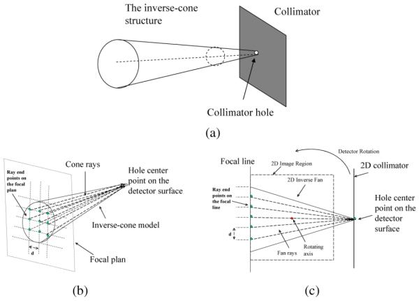
A resolution-compensation method that incorporates an inverse-cone model was proposed in [22]. The basic idea of this approach is to assume the field-of-view (FOV) of each hole is of an inverse-cone shape due to the blurring effects caused by the geometrical aperture of the collimator, while the classic parallel-hole geometry assumes line or cylindrical FOV. The inverse-cone model is shown in Fig. 1(a) [22]. The inverse-cone structure of the blurring effects was considered and modeled in the projector and backprojector of a general iterative expectation maximization (EM) algorithm [22], [23]. The measurement at each detector bin was assumed to be a weighted sum of the line integrals of a series of projection rays within the cone [22]. The number of projection rays was determined by the length (2-D) or area (3-D) cross section made by the focal line (2-D) or focal plane (3-D) and the inverse-cone boundaries as shown in Fig. 1(b) and (c). The number of projection rays for each projection bin depends on the collimator hole size or hole angle. In this paper, the cone angle of the inverse cone is also called the hole angle. In reconstruction, for each projection bin of interests, all projections along the projection rays within the cone are summed up. The projection of each ray is weighted with a fixed geometric response factor [22], [23], [24]. The weight factor for each projection is calculated according to the ray angle and the cone-beam-geometry point-response function given in [22] and [25], which is also known as the “Chinese hat” function [25].
Fig. 1.
Geometry of the inverse-cone model: (a) inverse-cone model, (b) 3-D compensation geometry, (c) 2-D compensation geometry.
For a given hole size, the hole angle can be approximately calculated as
| (1) |
The hole features and the corresponding hole angles of the three collimators used in this paper are shown in Table I.
TABLE I.
Collimator Hole Features and Corresponding Cone Angles
| Collimator | Hole Diameter (mm) | Hole Length (mm) | Hole angle |
|---|---|---|---|
| GAP Philips | 1.4 | 25.4 | 3.1272° |
| HR Siemens | 1.11 | 24.05 | 2.644° |
| HR Siemens | 5.54 | 24.05 | 6.0456° |
III. Computer Simulations
A. Methods
To study the resolution-to-sensitivity tradeoff of different collimator holes in SPECT imaging, we investigated five collimator holes whose hole angles are 0.5, 1, 2, 3, and 4 times of 3.157°, respectively, (the GAP collimator hole angle). The first collimator has smaller holes than the GAP collimator. It can be regarded as an HR collimator. The third, fourth, and fifth collimators have larger holes than the GAP collimator, which can be regarded as HS collimators.
To simplify the simulations, we simulated 2-D SPECT reconstruction using a 2-D mathematical cardiac torso phantom (128 × 128) with 2-D blurring compensation. The projector/backprojector pair incorporated a 2-D version [an inverse-fan model shown in Fig. 1(c)] of the 3-D inverse-cone model in the reconstruction. Here, for each of the five collimator holes, compensation models with eight different compensation angles (0.04, 0.16, 0.29, 0.41, 0.58, 0.71, 0.83, and 1.00 times each collimator hole angle) were studied. We employed 200 detector positions over 360°. The image size was 128 × 128. The distance between the detector to the axis of rotation was set to be 100 pixels.
The sample points chosen on the focal line are the points on a grid with unit d = 1.0 × pixel for reconstruction and a finer grid with unit d = 0.5 × pixel for data acquisition simulation. Poisson noise was added to the simulation data. Images were reconstructed from both the noisy and noise-free simulation data for quantitative analysis. The sensitivity of each collimator was calculated using the equations given in [3] and [6].
The reconstructed images with different hole sizes and different compensation angles were compared based on contrast recovery coefficients (CRC) versus normalized standard deviation (STD) [26], [27]. CRC-STD curves can well present the trend of image contrast (resolution) recovery and noise amplification during the iteration reconstruction process. The CRC is defined as
| (2) |
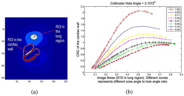
where Mcard and Mlung represent the mean of cardiac wall region-of-interest (ROI) and the mean of the ROI in the lung region, respectivley, as shown in Fig. 2(a). Here, we choose the cardiac wall and lung regions as the ROIs just for a general and relative CRC-STD comparison. For specific cardiac studies, other ROIs such as myocardium and ventricular chamber regions may be more preferable. The subscripts rec and phan denote reconstruction and phantom, respectively. The background mean Mlung was computed within the ROI in the uniform lung region. The cardiac wall to lung activity ratio of the phantom was 5:1. Note that we use normalized STD to measure the noise properties of the reconstruction due to the reason that for different image intensity levels, the same STD of the background noise can result in different image quality. Here, the STD is calculated using the formula
| (3) |
where σlung is the STD of the ROI in the lung region, N is the number of image elements that are used in the calculation, fi is the value of the ith element of the image reconstructed from noise data, and is the expected mean value of the ith element. Noise-free reconstruction is used to calculate .
Fig. 2.
(a) ROIs on the MCAT phantom image where CRC and STD are measured. (b) CRC versus STD performance for the GAP collimator with eight compensation angles. Markers in the figure represent different iterations.
B. Results
Fig. 2(b) shows the CRC-STD curves of the reconstructions using the GAP collimator (hole angle = 3.1572°) with the eight compensation angles mentioned earlier.
It can be seen that different compensation cone angles lead to different CRC-STD performance. For the first two large compensation angles (1.00 × 3.1572° and 0.83 × 3.1572°), reconstruction converged to images with overrecovered contrast (CRC is greater than 1.0), while the last two small compensation angles (0.04 × 3.1572° and 0.16 × 3.1572°) did not give complete recovery of the image contrast. The reason that different compensation angles lead to different CRC curves is due to the impacts of mismatched blurring models between acquisition simulation and image reconstruction, which is consistent to the findings published in [28], [29]. Theoretically, compensation angle should match the full collimator hole angle. But in practice, due to the limitations of the approximated model, matched compensation angle makes the algorithm ill-conditioned and unstable [1], [8], [26]. The reconstruction may converge to an overcorrected solution with overamplified noise as shown here. The optimal-compensation angle should provide the most accurate resolution recovery with reasonable low noise amplification. The optimal compensation angle found in this paper is around half of the hole angle, which matches our practise experience in applying this technique in 2-D and 3-D reconstruction.
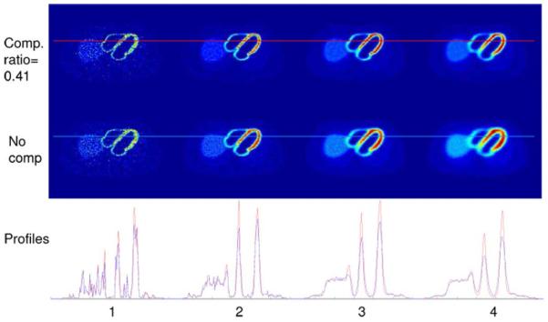
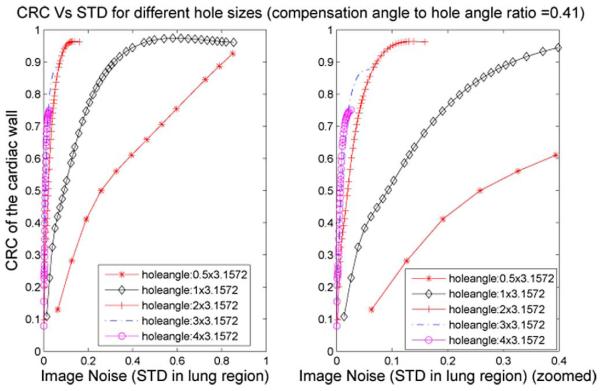
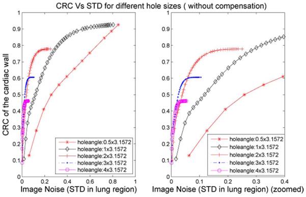
Fig. 3 shows the images reconstructed from the simulated datasets acquired with different hole angles. Four hole angles are studied as shown in the four columns: 1.0 × 3.1572°, 2.0 × 3.1572°, 3.0 × 3.1572°, and 4.0 × 3.1572°, respectively. Images reconstructed with a compensation angle to hole angle ratio of 0.41 are shown in the first row, while images reconstructed without compensation are shown in the second row. Profiles are plotted for comparison in the third row. One can see that images with blurring compensation have better resolution and finer image quality. The CRC-STD curves of this comparison study with five hole angles are also shown in Figs. 4 and 5. Blurring compensation significantly improves the resolution-noise performance of the reconstructed images for the latter three cases of large hole sizes. For the two middle hole sizes, 2.0 × 3.1572° and 3.0 × 3.1572°, reconstructions achieve identical resolution recovery to that of the GAP 1.0 × 3.1572° hole angle with much less STD. The blurring of the largest collimator hole size, 4.0 × 3.1572°, is too severe that the contrast was not able to be fully restored, while for the smallest hole size 0.5 × 3.1572°, blurring compensation does not show much effects as the blurring is rather minimal.
Fig. 3.
Images reconstructed with a compensation angle to hole angle ratio of 0.41 (first row) and without compensation (second row) from blurred simulations with hole angles equal to 1, 2, 3, and 4 times 3.1572°, from left to right, respectively. Images are all reconstructed with 200 iterations. Horizontal profiles of the reconstruction images with compensation (in red) and without compensation (in blue) are plotted in the bottom row. Red and blue lines in the reconstructed images indicate the locations of the profiles being plotted.
Fig. 4.
CRC versus STD for images reconstructed with different hole angles. Compensation angle to hole angle ratio = 0.41. (The STD range (0–0.4) of the left figure is zoomed and showed on the right.)
Fig. 5.
CRC versus STD for images reconstructed with different hole angles. No compensation is applied. (The STD range (0–0.4) of the left figure is zoomed and showed on the right.)
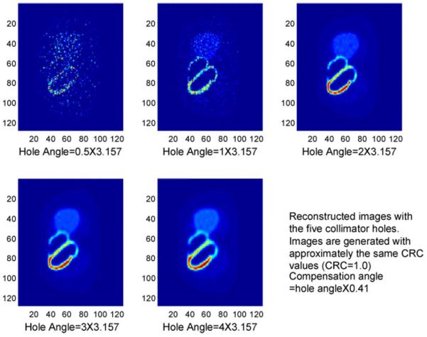
Fig. 6 shows the images reconstructed using the five collimator holes at approximately the same CRC (≈1.0). One can see that images generated using the first two collimator holes are quite noisy due to the small hole angles. Image generated using the two larger holes (2 × 3.157° and 3 × 3.157°) are much less noisy. Image resolution in these two cases can be successfully recovered using the inverse-cone model and are almost identical.
Fig. 6.
Image reconstructed using the five collimator hole sizes with fixed CRC and fixed compensation-angle to hole-angle ratio.
IV. Phantom Studies
A. Cardiac Insert Phantom Without Defect
1) Methods
To further investigate LEHR collimation versus LEHS collimation with resolution compensation in clinical environment, a phantom study was carried out on a Siemens e.Cam Signature SPECT system. A cardiac insert phantom [see Fig. 7(a)] was loaded with 99mTc.
Fig. 7.
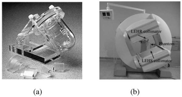
(a) Cardiac insert phantom. (b) Scan geometry.
A Siemens LEHR (hole diameter = 1.11 mm, length = 24.05 mm) and a Siemens LEHS collimators were mounted on the two detector heads, respectively. The image size was set to be 128 × 128 × 128. To make a fair comparison, two heads acquired data simultaneously as shown in Fig. 7(b). Each head acquired 60 projection views over 180°. The total study time was 60 min. Data were then separated into two datasets to obtain different statistics (one 10-min scan represents a low-count scan and one 50-min scan represents a high-count scan). For each projection, the data were acquired into 128 × 128 arrays. The distance from the face of the collimator to the axis of rotation was 24 cm. The total counts acquired by the detector with the LEHR collimator were 1.3417 million, while the total counts acquired by the one with the LEHS collimator were 5.7845 million.
2) Results
We first investigated 2-D maximum-likelihood EM (ML-EM) reconstructions with and without 2-D resolution compensation. The combined data (50-min scan plus the 10-min scan) were used. The central slice of the 3-D image was reconstructed on a Dell 8300 workstation. The images reconstructed from the data acquired by the LEHR collimator without resolution compensation are shown in Fig. 8(a), while the ones reconstructed from the data acquired by the LEHS collimator without compensation are shown in Fig. 8(b). The subfigures in these images were generated after different iterations. From Fig. 8(a) and (b), we can see that the center slice reconstructed from the HS data is less noisy but more blurred than the images reconstructed from HR data. Fig. 9(a) and (b) shows the images reconstructed from the LEHR and the LEHS data with resolution compensation, respectively. One can see that image quality is significantly improved with 2-D resolution compensation. The images shown in Fig. 9(a) and (b) are comparable in resolution, while the images shown in Fig. 9(b) are less noisy than those shown in Fig. 9(a). With a larger cost on computation, images reconstructed from HS data with 2-D resolution compensation achieve better noise-to-resolution performance than those reconstructed from HR data with 2-D resolution compensation. Because of a wider blurring angle, the reconstruction of the HS data requires more computations for iteration and, thus, takes much longer time, compared to the reconstruction from the HR data.
Fig. 8.
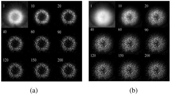
(a) Image reconstructed from the LEHR data without compensation. The white number at the upper-left corner of each image indicates the iteration number associated. (b) Image reconstructed from the LEHS data without compensation. The white number at the upper-left corner of each image indicates the iteration number associated.
Fig. 9.
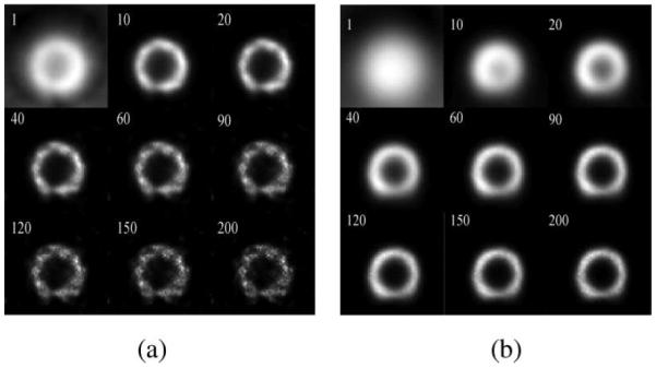
(a) Image reconstructed from the LEHR data with compensation. The white number at the upper-left corner of each image indicates the iteration number associated. (b) Image reconstructed from the LEHS data with compensation. The white number at the upper-left corner of each image indicates the iteration number associated.
In order to compare the HS and the HR systems more accurately, we also reconstructed the data using 3-D ordered subsets EM (OS-EM) algorithm with 3-D resolution compensations. Both the low-count data (10 min scan time) and the high-count data (50 min scan time) for LEHR and LEHS were applied. A 3-D resolution compensation model [22] was implemented in the reconstruction. Images reconstructed without resolution compensation were also generated for comparison purposes. Fig. 10(a) and (b) represents the nonresolution-corrected images from the high-count data, respectively, while Fig. 11(a) and (b) shows the images reconstructed with 3-D resolution compensation from the same dataset. Images with 3-D resolution compensation and the low-count data are shown in Fig. 12(a) and (b).
Fig. 10.
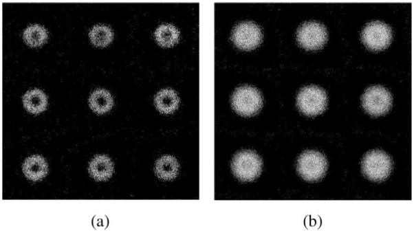
(a) 3-D image reconstructed from the high-count LEHR data without compensation (OS-EM: eight subsets and three iterations). Each subfigure (in row order from top to bottom) represents a transaxial slice of the 3-D image (slice 60–68, respectively). (b) 3-D image reconst6ructed from the high-count LEHS data without compensation (OS-EM: eight subsets and three iterations). Each subfigure (in row order from top to bottom) represents a transaxial slice of the 3-D image (slice 60–68, respectively).
Fig. 11.
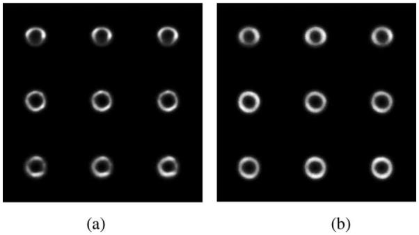
(a) 3-D image reconstructed from the high-count LEHR data with 3-D resolution compensation (OS-EM: eight subsets and three iterations). Each subfigure (in row order from top to bottom) represents a transaxial slice of the 3-D image (slice 60-68, respectively). (b) 3-D image reconstructed from the high-count LEHS data with 3-D resolution compensation (OS-EM: eight subsets and ten iterations). Each subfigure (in row order from top to bottom) represents a transaxial slice of the 3-D image (slice 60-68, respectively).
Fig. 12.
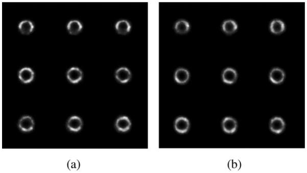
(a) 3-D image reconstructed from the low-count LEHR data with 3-D resolution compensation (OS-EM: eight subsets and three iterations). Each subfigure (in row order from top to bottom) represents a transaxial slice of the 3-D image (slice 60–68, respectively). (b) 3-D image reconstructed from the low-count LEHS data with 3-D resolution compensation (OS-EM: 8 subsets and 13 iterations). Each subfigure (in row order from top to bottom) represents a transaxial slice of the 3-D image (slice 60-68, respectively).
From the nonresolution-corrected images [see Fig. 10(a) and (b)], one can see that the LEHS images are severely blurred due to the large hole size of the collimator, while the statistics of the image is improved. With a properly tuned 3-D resolution-compensation model, the resolutions of both the LEHR images and the LEHS images can be recovered. For high-count data, comparing Fig. 11(a) with Fig. 11(b), image resolutions of the two images are quite comparable, while the LEHS images [see Fig. 11(b)] maintain a better uniformity in the cardiac wall region, and are less noisy compared to the LEHR images. For low-count data, similar results are shown in Fig. 12(a) and (b). It is more obvious in low-count images that with a proper compensation, LEHS can achieve better image quality than LEHR in terms of noise-to-contrast tradeoffs. This result suggests that LEHS is potentially a better collimator for low statistics clinical scans. The high-count rate of the LEHS collimator will benefit image noise property, while resolution loss can be recovered by compensation model for the cardiac study. Case-by-case studies may be needed to fine tune the compensation model.
B. Cardiac Insert Phantom With Defect
An additional low-count phantom study was performed to compare the LEHR collimator with the LEHS collimator with resolution compensation. This study aimed to simulate a low-count clinical case for cardiac study. Similar to the first phantom study, the LEHR and the LEHS collimators were mounted to each head of the Siemens SPECT scanner. A cardiac phantom with a defect was scanned. The defect is a cold lesion in the myocardium. Its size is 2 cm × 2 cm × 1 cm. The activity in the cold lesion is zero. To make a fair and easy comparison, the phantom was scanned by each detector head with 5 s per view and 128 views over 360°. The total counts acquired by the detector with the LEHR and the LEHS collimators were 1.6 and 6.9 million, respectively. Data acquired by the two collimators were reconstructed separately. The LEHR image was reconstructed using OS-EM with 32 subsets and 2 iterations without resolution compensation. Resolution compensation with a 3.0228° (half of the hole angle) compensation angle was applied in the LEHS reconstruction. LEHS images were reconstructed using OS-EM with 32 subsets and 2, 5, and 10 iterations, respectively.
Fig. 13 shows the reconstructed image slices and profiles reconstructed from the LEHR and LEHS datasets. It can be seen that because the counts are low, LEHR images look very noisy and the structure of the phantom cannot be clearly resolved. LEHS images preserve good image quality with significantly lower noise. The profile comparison between the LEHR and the LEHS images also shows that the LEHS reconstruction with resolution compensation achieves similar resolution with a smoother profile compared to the LEHR reconstruction.
Fig. 13.
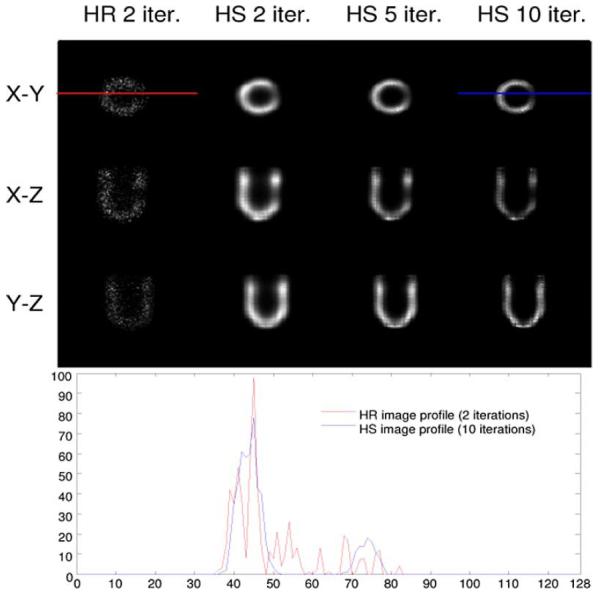
Image slices reconstructed from the low-count LEHR data (upper first column) and low-count LEHS data with compensation (upper second, third, and fourth columns) with different numbers of iterations: the X-Y, Y-Z, and X-Z central slices of the 3-D LEHR and LEHS images are shown in the upper three rows, respectively. Profiles indicated by the red and blue lines in the image slices are shown at the bottom. Profiles are drawn across on the defect area. Here, two iterations were applied to the LEHR reconstruction to achieve convergence with a comparable contrast to the LEHS reconstruction.
V. Conclusion and Future Work
HR collimators may be desirable for small lesion detection in oncology. However, the low sensitivity of the HR collimator results in noisy images, which may not be a good option for cardiac SPECT studies. Using HS collimators can improve the detection sensitivity at a cost of losing image resolution. An inverse-cone resolution-compensation model proposed in [22] can be one of the models incorporated in the reconstruction to compensate for the blurring effects. In this paper, we first used the computer simulations to study the capability of recovering image resolution using the inverse-cone model for five collimator hole sizes. Results show that using the first two types of small collimator holes (smaller or equal to the GAP collimator holes) leads to very noisy images and minimal improvement is visible. For the holes that are two or three times larger than the GAP collimator hole, the resolution compensation model can significantly improve the image quality in terms of noise-to-resolution tradeoff, and provides less noisy images with almost identical resolution to that of the GAP hole size. For the last case in which the hole is four times larger than the GAP collimator hole, the blurring effects are too severe, and image resolution cannot be completely recovered. It is not always true that an HS collimator with resolution compensation techniques can outperform the HR collimator for cardiac imaging. Resolution-compensation techniques would fail for certain level of resolution blurring, for an example, imaging with no collimation. An HS collimator with hole angle between 6.3° and 9.4° are suggested in this paper for using the “inverse-cone” resolution compensation technique.
Two phantom experiments also confirm that images reconstructed from HS data are less noisy than those reconstructed from HR data. With collimator-blurring compensation, the HS images can have the comparable resolutions to the HR images, while HS images look much smoother than the HR images due to their better noise properties. This could benefit cardiac study and especially for low-dose studies in a real clinical environment. These results are also consistent to the findings of an early published comparison study between cardiac SPECT collimators [28].
The performance of each collimator is highly depended upon the compensation model as well as the reconstruction algorithm. We have shown that the widely used LEHR collimator in clinic is not optimal, especially, for cardiac SPECT imaging, in terms of the sensitivity-to-resolution tradeoff compared to the LEHS collimator with our compensation model. However, the optimal collimator and matched compensation models need to be carefully and further investigated for practical usage in SPECT clinical imaging. Here, we only investigated one compensation approach and simple ML-EM/OS-EM algorithm with line integral projectors. Other compensation modeling approaches and reconstruction algorithms should also be studied. In addition, in real cases, factors like attenuation and scatter could also affect image quality and, thus, should be considered together with collimator blurring.
Acknowledgments
This work was supported in part by the U.S. National Institutes of Health under Grant 1R33 EB001489-01A2 and Grant 1R21 EB003298-01.
Biography

Bin Zhang received the Ph.D. degree in electrical and computer engineering from The University of Utah, Salt Lake City.
He is currently an Imaging Physicist at the Philips Medical Systems, Cleveland, OH. His research interests include single photon emission computed tomography/positron emission tomography image reconstruction, data correction, and system modeling and analysis.

Gengsheng L. Zeng received the Ph.D. degree in electrical and computer engineering from the University of New Mexico, Albuquerque.
He is currently a Professor in the Department of Radiology, Utah Center for Advanced Imaging Research, The University of Utah, Salt Lake City. His research interests include single photon emission computed tomography image reconstruction algorithm and instrumentation development.
Contributor Information
Bin Zhang, The University of Utah, Salt Lake City, UT 84108 USA. He is now with the Philips Medical Systems, Cleveland, OH 44143 USA (bin.zhang_3@philips.com)..
Gengsheng L. Zeng, Department of Radiology, Utah Center for Advanced Imaging Research, The University of Utah, Salt Lake City, UT 84108 USA (larry@ucair.med.utah.edu).
References
- [1].Wernick MN, Aarsvold JN. Emission Tomography: The Fundamentals of PET and SPECT. Elsevier; Amsterdam, The Netherlands: 2004. [Google Scholar]
- [2].Lau YH, Hutton BF, Beekman FJ. Choice of collimator for cardiac SPET when resolution compensation is included in iterative reconstruction. Eur. J. Nucl. Med. 2001;47:28–39. doi: 10.1007/s002590000387. [DOI] [PubMed] [Google Scholar]
- [3].Zeng GL, Gullberg GT. A channelized-hotelling-trace collimator design method based on reconstruction rather than projection. IEEE Trans. Nucl. Sci. 2002 Oct.49(no. 5):2155–2158. [Google Scholar]
- [4].Metz CE, Atkins FB, Beck RN. The geometric transfer function component for scintillation camera collimators with straight parallel holes. Phys. Med. Biol. 1980;25:1059–1070. doi: 10.1088/0031-9155/25/6/003. [DOI] [PubMed] [Google Scholar]
- [5].Tsui BMW, Gullberg GT. The geometric transfer function for cone and fan beam collimators. Phys. Med. Biol. 1990;35:81–93. doi: 10.1088/0031-9155/35/1/008. [DOI] [PubMed] [Google Scholar]
- [6].Gunter DL, et al. Collimator characteristics and design. In: Henkin RE, et al., editors. Nuclear Medicine. Mosby; St. Louis, MO: 1996. pp. 96–124. [Google Scholar]
- [7].Tsui BMW, Hu HB, Gilland DR, Gullberg GT. Implementation of simultaneous attenuation and detector response correction in SPECT. IEEE Trans. Nucl. Sci. 1988 Feb.35(no. 1):778–783. [Google Scholar]
- [8].King MA, Glick SJ, Pretorius PH, Wells RG, Gifford HC, Narayanan MV, Farncombe T. Attenuation, scatter, and spatial resolution compensation in SPECT. 2004 [Online]. Available: http://wachusett.umassmed.edu/king/
- [9].Madsen MT. A method for obtaining an approximate Wiener filter. Med. Phys. 1990;17:126–130. doi: 10.1118/1.596542. [DOI] [PubMed] [Google Scholar]
- [10].King MA, Schwinger RB, Doherty PW, Penney BC. Two-dimensional filtering of SPECT images using the Metz and Wiener filters. J. Nucl. Med. 1984;25:1234–1240. [PubMed] [Google Scholar]
- [11].Glick SJ, Penney BC, King MA, Byrne CL. Noniterative compensation for the distance-dependent detector response and photon attenuation in SPECT imaging. IEEE. Trans. Med. Imag. 1994 Jun.13(no. 2):363–34. doi: 10.1109/42.293929. [DOI] [PubMed] [Google Scholar]
- [12].Soares EJ, Glick SJ, King MA. Noise characterization of combined Bellini-type attenuation correction and frequency-distance principle restoration filtering. IEEE Trans. Nucl. Sci. 1996 Dec.43(no. 6):3278–3290. [Google Scholar]
- [13].Zeng GL, Gullberg GT. Unmatched projector/backprojector pairs in an alternative iterative reconstruction algorithm. IEEE Trans. Med. Imag. 2000 May;19(no. 5):548–555. doi: 10.1109/42.870265. [DOI] [PMC free article] [PubMed] [Google Scholar]
- [14].Bai C, Zeng GL, Gullberg GT, DiFilippo F, Miller S. Slab-by-slab blurring model for geometric point response correction and attenuation correction using iterative reconstruction algorithms. IEEE Trans. Nucl. Sci. 1998;45:2168–2173. [Google Scholar]
- [15].Tsui BMW, Jaszczak RJ. Incorporation of detector response in projector and backprojector for SPECT image reconstruction. J. Nucl. Med. 1987;28:566. [Google Scholar]
- [16].Formiconi AR, Pupi A, Passeri A. Compensation of spatial system response in SPECT with conjugate gradient reconstruction technique. Phys. Med. Biol. 1989;34(no. 1):69–84. doi: 10.1088/0031-9155/34/1/007. [DOI] [PubMed] [Google Scholar]
- [17].Penney BC, King MA, Knesaurek K. A projector, backprojector pair which accounts for the two-dimensional depth and distance dependent blurring in SPECT. IEEE Trans. Nucl. Sci. 1991 Apr.37(no. 2):681–686. [Google Scholar]
- [18].Liang Z. Compensation for attenuation, scatter, and detector response in SPECT reconstruction via iterative FBP methods. Med. Phys. 1993;20:1097–1106. doi: 10.1118/1.597006. [DOI] [PubMed] [Google Scholar]
- [19].Pan TS, Luo DS, Kohli V, King MA. Influence of OSEM, elliptical orbits, and background activity on SPECT 3D resolution recovery. Phys. Med. Biol. 1997;42:2517–2529. doi: 10.1088/0031-9155/42/12/015. [DOI] [PubMed] [Google Scholar]
- [20].King M, Pan TS, Luo DS. An investigation of aliasing with Gaussian-diffusion modeling of SPECT system spatial resolution. IEEE Trans. Nucl. Sci. 1997 Jun.44(no. 3):1375–1380. [Google Scholar]
- [21].Hutton BF, Lau YH. Application of distance-dependent resolution compensation and post-reconstruction filtering for myocardial SPECT. Phys. Med. Biol. 1998;43:1679–1693. doi: 10.1088/0031-9155/43/6/022. [DOI] [PubMed] [Google Scholar]
- [22].Zeng GL, Gullberg GT. Three-dimensional iterative reconstruction algorithms with attenuation and geometric point response correction. IEEE. Trans. Nucl. Sci. 1991 Apr.38(no. 2):693–702. [Google Scholar]
- [23].Nowak DJ, Eisner RL, Fajman WA. Distance-weighted backprojection: A SPECT reconstruction technique. Radiology. 1986;159:531–536. doi: 10.1148/radiology.159.2.3485803. [DOI] [PubMed] [Google Scholar]
- [24].Tanaka E. Quantitative image reconstruction with weighted backprojection for single photon emission computed tomography. J. Comut. Assist. Tomogr. 1983;7:692–700. doi: 10.1097/00004728-198308000-00021. [DOI] [PubMed] [Google Scholar]
- [25].Bracewell R. Fourier Analysis and Imaging. Plenum; New York: 2004. [Google Scholar]
- [26].Liow JS, Strother SC. Practical tradeoffs between noise, quantitation, and number of iterations for maximum likelihood-based reconstructions. IEEE Trans. Med. Imag. 1991 Dec.10(no. 4):563–571. doi: 10.1109/42.108591. [DOI] [PubMed] [Google Scholar]
- [27].Zhang B, Zeng GL. An immediate after-backprojection filtering method with blob-shaped window functions for voxel-based iterative reconstruction. Phys. Med. Biol. 2006;51:5825–5842. doi: 10.1088/0031-9155/51/22/007. [DOI] [PubMed] [Google Scholar]
- [28].Wilson DW, Barrett HH. The effects of incorrect modeling on noise and resolution properties of ML-EM images. IEEE. Trans. Nucl. Sci. 2002 Jun.49(no. 3):768–773. doi: 10.1109/TNS.2002.1039561. [DOI] [PMC free article] [PubMed] [Google Scholar]
- [29].Gifford HC, King MA. Impact of mismatched detector-blur models on 6 7Ga SPECT Tumor Detection. Proc. IEEE. Nucl. Sci. Symp. Conf. Rec. 2007;6:4226–4229. doi: 10.1109/NSSMIC.2007.4437050. [DOI] [PMC free article] [PubMed] [Google Scholar]


