Significance
Metamaterials provide additional venues for routing and shaping waves, as well as manipulating wave–matter interactions. In principle, similar concepts and techniques could be applied to engineer the properties of quantized fields. Here, we theoretically demonstrate that structures with a near-zero refractive index are capable of inhibiting and then selectively exciting electric field vacuum fluctuations. This effect might offer different pathways to manipulate quantized fields with metamaterials. We illustrate this point by investigating the decay dynamics of a quantum emitter embedded in a zero-index shell. For this particular example, we theoretically show how the distinctive features of zero-index media enable unique phenomena, such as a direct modulation of the vacuum Rabi frequency by deforming the zero-index shell.
Keywords: metamaterial, quantum optics, near-zero refractive index, ENZ, vacuum fluctuation
Abstract
Vacuum fluctuations are one of the most distinctive aspects of quantum optics, being the trigger of multiple nonclassical phenomena. Thus, platforms like resonant cavities and photonic crystals that enable the inhibition and manipulation of vacuum fluctuations have been key to our ability to control light–matter interactions (e.g., the decay of quantum emitters). Here, we theoretically demonstrate that vacuum fluctuations may be naturally inhibited within bodies immersed in epsilon-and-mu-near-zero (EMNZ) media, while they can also be selectively excited via bound eigenmodes. Therefore, zero-index structures are proposed as an alternative platform to manipulate the decay of quantum emitters, possibly leading to the exploration of qualitatively different dynamics. For example, a direct modulation of the vacuum Rabi frequency is obtained by deforming the EMNZ region without detuning a bound eigenmode. Ideas for the possible implementation of these concepts using synthetic implementations based on structural dispersion are also proposed.
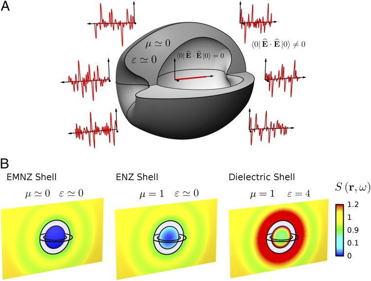
Vacuum fluctuations, the fluctuations of a quantized field on its vacuum state around its zero average (1), are considered one of the most distinctive (1–3) and disputed (4) aspects of quantum optics and quantum field theory. Although direct measurements of vacuum fluctuations have only been proposed very recently (5), they are the attributed source of numerous nonclassical phenomena, including, for instance, spontaneous emission (6), Lamb shift (7), Casimir forces (8), molecular energy transfer (9), quantum friction (10), as well as several vacuum amplification effects (3). It is also a well-established fact that macroscopic bodies modify the structure of electromagnetic fields, opening up the possibility of engineering all aforementioned effects (6, 11). For example, because quantum fields fluctuate in a space empty of matter, we could ask what should be the matter filling the space to first inhibit and then selectively engineer vacuum fluctuations (Fig. 1A). Traditional answers to this question have appeared in the form of photonics crystals (PCs) (12–15) and closed cavities (16–18), leading to formidable advances in the ability to control light–matter interactions. In essence, the geometry of periodic structures and resonators can be engineered in such a way so that they do not support eigenmodes on a given frequency range. Here, we demonstrate theoretically that epsilon-mu-near-zero (EMNZ) media (19), also known as matched zero-index (ZI) media (20), that is, a medium with simultaneously zero permittivity and permeability, behaves as a natural inhibitor of vacuum fluctuations. Thus, we propose ZI structures as an alternative platform to manipulate spontaneous emission, and other related effects, possibly leading to the exploration of qualitatively different decay dynamics.
Fig. 1.
Inhibiting and engineering vacuum fluctuations with macroscopic media. (A) Conceptual sketch of an epsilon-and-mu-near-zero (EMNZ), , shell that inhibits vacuum (electric field) fluctuations within the region encapsulated by it. (B) Spectral density of vacuum (electric field) fluctuations, , normalized to its free-space counterpart, in the presence of ideally lossless EMNZ, epsilon-near-zero (ENZ) ( and dielectric ( spherical shells of internal and external radii and , respectively.
Note than one could conceivably approach this problem by using a canonical quantization procedure (1). In this manner, we could consider a space filled with a substance of refractive index , and carry out the conventional quantization approach based on a cubic cavity of side (1). In doing so, it is evident that the density of states obtained in the limit, , would be completely depleted in media with a zero-refractive index . This analysis presents an interesting perspective, in which ZI media can be considered somewhat analogous to PCs materials and closed cavities in as far as they deplete the space of electromagnetic modes. However, despite providing a nice intuition, this model does not capture the necessary dispersive properties of ZI media (19). Moreover, it also fails to account for the interaction of a small quantum system [e.g., a quantum emitter (QE) such as an atom or a quantum dot] and macroscopic media, because the QE must be insulated from the background macroscopic bodies to produce a consistent result (21, 22). However, this preliminary consideration identifies ZI media as a potential candidate to inhibit vacuum fluctuations and spontaneous emission.
Macroscopic Quantum Electrodynamics
Therefore, to elucidate the main features of vacuum fluctuations in the presence of ZI media, as well as their interaction with QEs, we describe the system by using the known macroscopic quantum electrodynamics tools developed for the analysis of dispersive media (6, 23). For the sake of simplicity, we assume that the space is filled with an inhomogeneous medium characterized by relative permittivity, , and relative permeability, . Under this framework, the excitations of the EM fields–matter system are represented by a continuum of harmonic oscillators with associated polaritonic operators (). The Hamiltonian of this matter–field system is , and the electric field operator is given by , where . Here, we use the definitions and , where is the classical Green dyadic function of the background medium. See refs. 6 and 23 for more details of this quantization approach.
Vacuum Fluctuations
It can be readily checked from the above formalism that the expectation value of the electric field on its vacuum state is zero . However, the expectation value of the field intensity operator is nonzero , leading to the so-called vacuum fluctuations (1). Specifically, it can be demonstrated by using properties of the Green function that vacuum fluctuations in the presence of macroscopic media can be compactly written as , with being defined as the spectral density of vacuum (electric field) fluctuations. For example, in free space, we have a uniform distribution .
However, can be engineered by using macroscopic media, and next we find that within bodies of arbitrary geometry immersed within an EMNZ body of arbitrary geometry. This effect can be demonstrated by noting that is proportional to the time-averaged power supplied by a classical current moment located at , oriented along , and oscillating at frequency ω: (24). In addition, it follows from Poynting’s theorem that, for vanishingly small losses, equals the power radiated outside the EMNZ body by this classical source (24). Furthermore, we note that EMNZ forms the so-called a DB boundary (25), that is, because and within the EMNZ body, then the normal components of the and must vanish in the external surface of the EMNZ body to satisfy the continuity of and across the interface. However, it can be proven (26) that fields outside the EMNZ body are uniquely determined by the normal components of the and . Therefore, this is sufficient to prove that, if a classical dipole is located within a body immersed in a finite-size EMNZ region, then the fields excited in the unbounded region outside to the finite EMNZ region are zero. Consequently, the power supplied by the classical source in the lossless limit is zero, and hence , and . In conclusion, the spectral density of vacuum (electric field) fluctuations within bodies immersed in an ideal EMNZ host is zero.
This effect can be appreciated in Fig. 1B, which depicts the numerical prediction for , normalized to its free-space counterpart , in the presence of an EMNZ shell. For the sake of simplicity in the numerical calculations, we consider a spherical shell with internal and external radii , respectively. For comparison, Fig. 2B also depicts for an epsilon-near-zero (ENZ) [i.e., ] and a dielectric [i.e., ] shells of the same geometrical characteristics. It is clear that both shells also perturb , but they do not suppress it in their whole internal regions. However, it is worth noting that the ENZ shell does suppress at the center of the system. This effect is associated the excitation of a nonradiating mode exhibiting a spatially electrostatic distribution (with zero magnetic field) in the ENZ shell (27). Furthermore, this example reveals that, even if only nonmagnetic () materials are available, media with near-zero parameters can still suppress vacuum fluctuations in some specific configurations.
Fig. 2.
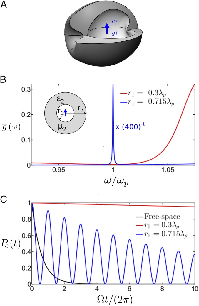
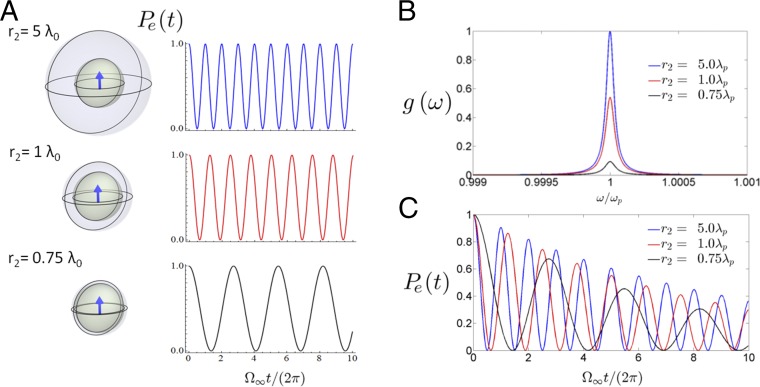
Decay dynamics of a quantum emitter (QE) within an ENZ shell. (A) Conceptual sketch of a QE embedded within a macroscopic EMNZ shell of arbitrary shape. (B) Spectral density normalized to its free-space counterpart, for a QE positioned at the center of a spherical shell with external radius , and internal radius of (red) and (blue). The shell is characterized by relative permeability, , and relative permittivity, , with , and (Inset) Sketch of the geometry. (C) Time evolution of the probability of occupation of the excited state, , for nonresonant case of and resonant case of internal radii. For comparison, the black line shows the decay in free space. The magnitude of the transition dipole moment is fixed such that .
We note that the Green function can be written as the sum of two parts, , corresponding to the free-space Green function [i.e., the Green function corresponding to a space empty of matter Im ], and a scattering part (i.e., the part that takes into account the scattering of the free-space fields by the background media) (21). Under this perspective, the mechanism of the EMNZ body is similar to a scattering cancellation cloak (28). That is to say, a given region of space is covered with the appropriate material to obtain a cancellation condition . In this manner, the EMNZ region could also be intuitively understood as a vacuum fluctuation “cloak” at a given frequency.
Several realizations of EMNZ media have been proposed in the form of all-dielectric metamaterials (29, 30), photonic crystals (31, 32), and waveguides (33). Naturally, practical implementations of EMNZ media are necessarily dispersive (19). Therefore, just like scattering cancellation cloaks, a passive vacuum-fluctuation cloak would only be able to reduce for a finite bandwidth (34, 35). However, as shown in the next section, this is sufficient to provide additional degrees of freedom in engineering relatively narrow band vacuum-fluctuation–assisted effects, for example, spontaneous emission. Furthermore, and also in analogy with advances in scattering cancellation cloaks (36), the bandwidth over which the vacuum fluctuations are reduced could be expanded by using active macroscopic media.
Decay Dynamics via Spontaneous Emission
We illustrate the applicability of EMNZ and ENZ shells as an alternative platform to engineer the decay dynamics of an initially excited QE (Fig. 2A). The QE is modeled as a two-level system with transition dipole moment , and transition frequency . Thus, the QE and interaction Hamiltonians are given by and , respectively, with . We assume that the QE is positioned at the center of a shell of internal and external radii and , respectively. We show that the response of EMNZ and ENZ shells for this configuration is identical (SI Methods, Spectral Density Within EMNZ and ENZ Spherical Shells), and we simply consider an ENZ shell with relative permittivity with (Inset of Fig. 2B).
Assuming a single excitation, the state of the system is , and the probability of occupation of the excited state is found refs. 6 and 37 from the solution to the following: . Here, the memory kernel is determined by the so-called spectral density , which is proportional to the density of vacuum fluctuations at the position of the QE and for the polarization of its electric dipole transition. In this canonical core–shell geometry, the spectral density at the plasma frequency is identical for EMNZ and ENZ shells, and it can be written as follows (SI Methods, Spectral Density Within EMNZ and ENZ Spherical Shells):
| [1] |
Here, is a geometrical parameter, and , with being the free-space spectral density. , where is the cylindrical Bessel function (38) of the first kind and order .
Eq. 1 ratifies that vanishes as , independently of the external radii and the properties of the space external to the shell. Thus, the QE decouples from the vacuum field and the dynamics of the system converge to an exponential decay with vanishing decay rate (note that the ENZ shell will induce a Lamb shift, which here we consider included in ). In other words, the spontaneous emission is inhibited due to the influence of ENZ or EMNZ shells. At the same time, it is clear from Eq. 1 that diverges at the zeros of the Bessel function , corresponding to the excitation of bound eigenmodes with spatially electrostatic field distributions studied in refs. 27, 39, and 40. In fact, we find that the spectral density for this resonant internal radius asymptotically converges to a Lorentzian line given by the following (SI Methods, Spectral Density Within EMNZ and ENZ Spherical Shells):
| [2] |
with oscillator strength,
| [3] |
and linewidth,
| [4] |
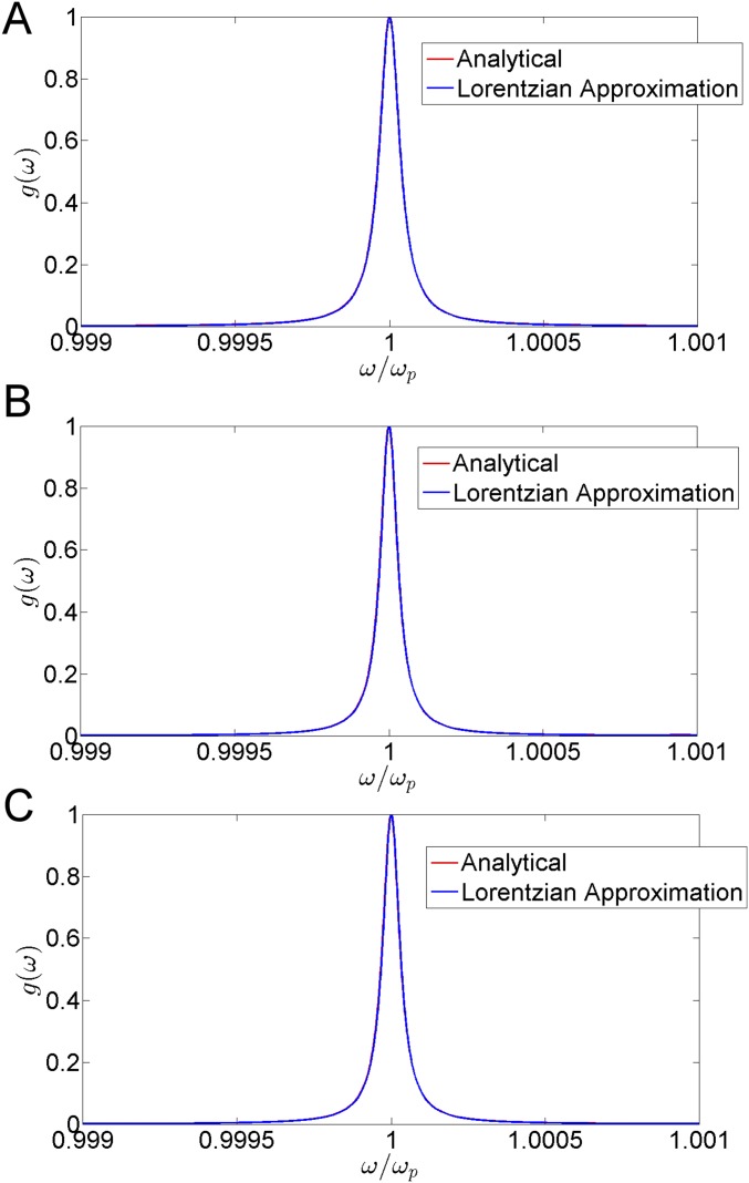
where . In addition, and are the asymptotic values of the oscillator strength and linewidth in the large shell limit, . Explicit expressions of and are reported in SI Methods, Spectral Density Within EMNZ and ENZ Spherical Shells, although they can be roughly approximated by and . The validity of this asymptotic limit is checked in Fig. S1. Note that the interaction of a QE with a Lorentzian line has a well-known solution (6), which results in the excitation of non-Markovian reversible processes in the form of Rabi oscillations, , with frequency .
Fig. S1.
Comparison of the analytic and asymptotic Lorentzian expressions of the spectral density. Spectral density, , normalized to its maximal value, at the center of the space encapsulated within a spherical ENZ shell with internal resonant radius (), and external radius of (A) , (B) , and (C) . The nonmagnetic shell is characterized by dispersive permittivity: with . The depicted values for both expressions are normalized to the maximal value of the analytical expression. Thus, the figure also illustrates the accuracy of the peak value predicted by the asymptotic expression.
Therefore, we conclude that, on the one hand, EMNZ and ENZ shells enable the suppression of spectral density and consequent inhibition of spontaneous emission, whereas, on the other hand, they also enable the controlled excitation of bound eigenmodes, and thus the potential triggering of reversible decay dynamics. Both effects can be clearly appreciated in Fig. 2 B and C, which represent, respectively, the normalized spectral density and the time evolution of the probability of occupation of the excited state, , for a shell with external radius , and for examples of nonresonant and resonant internal radii. For illustrative purposes, we set so that the resonance exhibits a linewidth on the same order of magnitude than those observed in the synthetic implementations presented later in Fig. 4. We also select the transition dipole moment such that , that is, so that we can clearly view and appreciate reversible dynamics with 10 oscillations before the probability of occupation decays to . The figures confirm that and the spontaneous emission are suppressed for the nonresonant radius, , whereas a resonant line and Rabi oscillations are observed for the resonant radius .
Fig. 4.
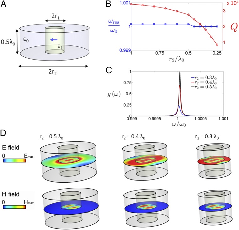
Synthetic implementation of ENZ shells as a microwave cylindrical resonator. (A) Geometry of the resonator: cylindrical resonator of height (with arbitrarily chosen value ) and radius , containing a dielectric rod of relative permittivity and whose radius is set to satisfy the resonance condition (). The resonator is bounded by copper walls (). Numerically simulated performance: (B) Eigenfrequency, , and quality factor , as a function of the external radius . (C) Spectral density, , normalized to the maximal computed value, for a QE located at with its dipole moment pointing along for three different external radii. (D) Electric and magnetic field magnitude distributions excited by such QE in the middle plane ().
In a way, the inhibition of spontaneous emission and subsequent excitation of bound eigenmodes in EMNZ and ENZ shells could be considered somewhat analogous to the response of photonic band gap and defect cavity modes in PCs, and/or single-mode closed cavities. However, by contrast with PCs and closed cavities, the EMNZ and ENZ shells can be of any size and shape (39), and it is also accessible from the outside by using nonlinear media (41). On top of that, we now demonstrate that it also provides additional degrees of freedom in tuning and engineering the decay dynamics that are essentially different from those of conventional cavities and PCs. To this end, we note that one remarkable property of the eigenmodes excited in EMNZ and ENZ shells is that their eigenfrequency is invariant with respect to geometrical transformations of the external boundary of the shell (39). This is in fact reflected in Eq. 2, because the resonant frequency of the Lorentzian line equals independently of . Next, we note from Eqs. 2–4 that compressing the shell from an infinite size () to an infinitesimal thickness (), shifts the vacuum Rabi frequency from to .
This effect is quite different from the behavior of conventional cavities. In fact, the resonance frequency of a conventional cavity is shifted by changing its size. Here, by contrast, we find that it is the vacuum Rabi frequency associated to a bound eigenmode (with fixed eigenfrequency) that changes as a function of the shell size (not the resonance frequency of the cavity). This effect is illustrated in Fig. 3A, which depicts time evolution of the probability of occupation of the excited state for ideally lossless ENZ shells with resonant internal radius and for different external radii. Therefore, in the same wave that perturbing a conventional cavity allow us to finely tune the resonance frequency (as it is done, for example, by introducing a screw in microwave cavities), we find that deforming a zero-index cavity enables us to finely tune the vacuum Rabi frequency without detuning the eigenfrequency of the cavity. Naturally, in the presence of losses, there is a nonzero resonance linewidth that would increase from to when compressing the cavity. This effect can be appreciated in Fig. 3B, which depicts the spectral density normalized to its peak value in the large shell limit for losses . Consequently, the oscillations in will be exponentially damped as it can be appreciated in Fig. 3C.
Fig. 3.
Decay dynamics under deformations of the external boundary. (A) Sketch of the geometry (not drawn to scale) and time evolution of the probability of occupation of the excited state, , for an ideally lossless ENZ shell [, , and ] with resonant internal radius , and for different external different radii . (B) Spectral density, normalized to the maximal computed value, for a lossy ENZ shell () for different external radii. (C) Time evolution of the probability of occupation of the excited state, , for the lossy ENZ shell. The magnitude of the transition dipole moment is fixed so that .
This is an example of the qualitatively different physics that could be observed using ZI shells as an alternative platform for manipulating light–matter interactions. Moreover, we emphasize that the same effect would appear in ENZ shells with an arbitrarily shaped external boundary (Fig. S2 for the analysis of a cubic cavity with “screw-like” deformations). It is also worth remarking that this effect is essentially different from detuning in conventional cavities, which decreases the strength of the oscillations as shown in Fig. S3. We anticipate that many other unique phenomena might emerge in more advanced configurations including complex QEs (e.g., multilevel or higher-order transitions), multimode cavities, more complex photonic states, systems driven by an external source, opto- and acousto-mechanical systems, etc.
Fig. S2.
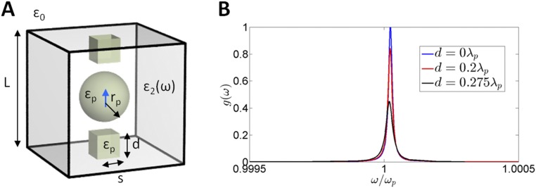
Cubic cavity under screw-like deformations. (A) Sketch of the geometry: open cubic cavity of side , immersed in an unbounded vacuum space, containing a dielectric sphere of permittivity and resonant radius , as wells as two “screws” consisting of dielectric blocks of square cross-section with side and variable height . The cavity is otherwise assumed to be filled with a nonmagnetic substance characterized by relative permittivity following a Drude model, with . A QE, modeled as a two-level system whose transition frequency equals the plasma frequency of the host medium filling the cavity, , is positioned at the center of the dielectric sphere. (B) Simulated spectral density, , normalized to the maximal computed value, for different screw heights: (no screws), , and . The figure confirms that screw-like deformations induce no significant detuning but significantly impact the peak value of the spectral density.
Fig. S3.
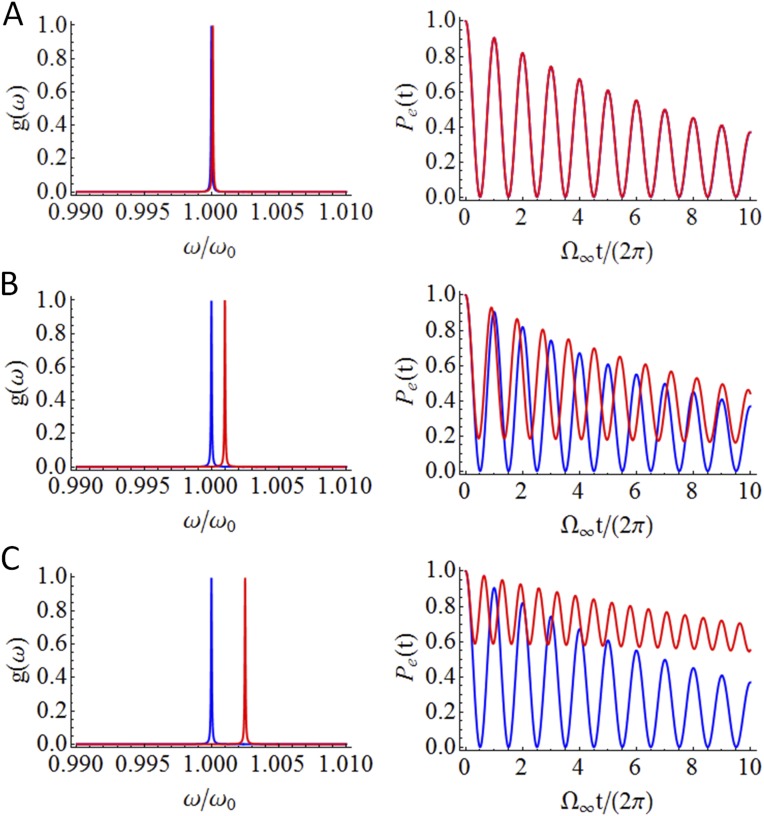
Impact of detuning on the spectral density and associated decay dynamics. Spectral density , normalized to its maximal value, and probability of occupation of the excited state, , for the configuration studied in Fig. 3 B and C of the main text (), but artificially introducing a detuning between the transition dipole frequency and the resonance frequency , such that , for (A) , (B) , and (C) . The figure reveals that detuning does not result in a modulation of the vacuum Rabi frequency, but instead it weakens the reversible dynamics.
Synthetic Implementations
The losses of naturally available ENZ materials might be too high to observe the effects predicted in Figs. 2 and 3. On the bright side, research on exotic phenomena excited in complex media is often transferred into the development of synthetic implementations of those effects that otherwise might have not been possible. Following this line of thought, we now demonstrate that decay dynamics identical to those induced by an ENZ shell can be excited in suitably designed cylindrical core–shell microwave resonators. We expect that this will facilitate the experimental validation of our theoretical results. The geometry of the proposed resonator is schematically depicted in Fig. 4A. It consists of a core–shell cylindrical resonator of internal and external radii and , respectively. Furthermore, the substance filling the core and shell regions are assumed to be characterized by relative permittivity and , respectively. We assume that this closed resonator is bounded by copper walls with finite conductivity (24) , although much higher quality factors could be easily obtained with superconducting cavities (42, 43).
Following other synthetic implementations of zero-index media in parallel-plate waveguides (33, 44), the height of the resonator is set to . However, here we study the TE11e and TM11o modes (38), whose explicit expressions for the field distribution are reported in SI Methods, Cylindrical Core–Shell Resonator. Although the field expressions are involved, the response of the system is simple: in the limit, the transversal propagation constant, , vanishes in the air-filled region. Then, the TE11e and TM11o modes collapse in the ( shell region into a single mode, whose field distribution in the middle plane () is identical to that excited by a 2D electrostatic dipole. In turn, the degeneracy in the shell provides the necessary degrees of freedom to ensure that, if we set the internal radius such that , then the resonator supports a hybrid TE11e–TM11o eigenmode independently of the external radius . This effect is clearly analogous to the localized mode excited in the spherical ENZ shell, which appears for (Eq. 1), independently of its external radius , and also exhibiting a spatially electrostatic field distribution.
To numerically test this effect, the core radius is set to satisfy (), and the external radius is compressed from to . The computed eigenfrequencies and quality factors, depicted in Fig. 4B, reveal that the resonance frequency only shifts a 0.01% when compressing the external boundary. On the contrary, the quality factor changes from 34,105 to 8,517. Then, if a QE is placed at the center of the resonator, it would mostly couple to this resonant mode, leading to dynamics as a function of the external radius similar to those depicted in Fig. 3. This effect is confirmed by computing for three different external radii (Fig. 4C). As expected, is characterized by a clear resonant line. In analogy with Fig. 3B, it is found that compressing the cavity from to reduces the peak of to a 24% of its original value without a significant detuning. In fact, the residual detuning, smaller than the linewidth, might be attributed to numerical precision. To complete the description, the electric and magnetic field magnitude distributions in the middle plane () and at the peaks of are reported in Fig. 4D. It is clear from the figure that field distribution in the shell region does indeed feature a spatially electrostatic (but temporally dynamic) field distribution in the middle plane.
We emphasize that, although we have studied the response of a closed core–shell cylindrical cavity, the same design strategy could be applied to a variety of configurations. In fact, the proposed resonator is very robust against deformations of the external boundary, and hence cylindrical resonators with arbitrary cross-sections could be used in practice (Fig. S4). Moreover, open systems with similar characteristics can be designed by using patterned surfaces that enforce the appropriate boundary conditions (45) (Fig. S5).
Fig. S4.
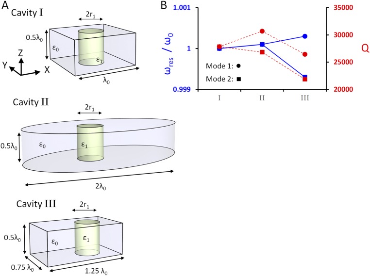
Synthetic implementations with different cross-sections. (A) Geometry of the resonators: cylindrical core–shell resonators of height [with ] and different cross-sections, containing a dielectric rod of relative permittivity and whose radius is set to satisfy the resonance condition, (). Cavity I: square cross-section of side . Cavity II: ellipse cross-section of major and minor axis of 2 and , respectively. The dielectric rod is shifted from the center of the ellipse by 0.25 along the x axis. Cavity III: rectangular cross-sections of sides 1.25 and 0.75 The dielectric rod is shifted from the center of the rectangle by 0.2 along the x axis. All resonators are bounded by copper walls characterized by finite conductivity . (B) Resonance frequency, , and quality factor, , for the two eigenmodes excited in the vicinity of The figure demonstrates that even very dramatic deformation of the external boundary result in minor detunings (all smaller than 0.1%).
Fig. S5.
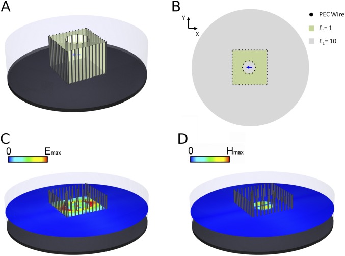
Synthetic implementation of an open ENZ shell based on patterned surfaces. (A) Three-dimensional view and (B) top view of the geometry of the system: a parallel-plate waveguide of height (with = 0.03 m at 10 GHz) is filled with a substance characterized by relative permittivity (the top plate is not depicted for illustrative purposes). The waveguide also contains an air () cylinder (green region) effectively acting as an “ENZ shell” () whose cross-section is constructed by the difference between a cylinder of square cross-section of side , and a circular cylinder of resonant radius such that (). Following ref. 45, all internal boundaries are covered by thin shorting wires of radius , to enable the accumulation of charge, thus enforcing the adequate boundary conditions. The top and bottom plates and the shorting wires are implemented with PEC materials. In the simulation, the external lateral wall of the waveguide is terminated in a scattering boundary condition to emulate an unbounded system. (C and D) Electric (C) and magnetic (D) field magnitude distributions in the middle plane () excited by a point dipole placed at the center of the system and oriented along . The field distributions evidence the correct operation of the system: the fields are trapped within the effective “ENZ shell” and the field distribution in this plane is spatially electrostatic (with zero magnetic field) within the effective ENZ shell. It is important to note that the shorting wires do not act as a metallic cage, because the fields excited by the point dipole are predominantly perpendicular to them.
Therefore, our results suggest that the proposed theoretical concepts could be experimentally validated in a number of microwave resonators. For instance, these resonators could be integrated into traditional setups for experiments of Rydberg atoms interacting with microwave photons in superconducting cavities (18). Also at microwave frequencies, most recent advances in research of vacuum fluctuations have been carried out in waveguide-based superconducting circuits (3). Thus, a promising line of research might be to redesign waveguide structures exhibiting zero-index modes [e.g., rectangular metallic waveguides at cutoff (33, 44), and/or transmission lines loaded with lumped elements (46)], to be integrated into those systems and observe the predicted effects. As for scaling the system to higher frequency regimes, there is a variety continuous media that exhibit ENZ properties at infrared frequencies. The moderate losses of these materials [e.g., for silicon carbide at λ ∼ 10.33 µm (47, 48), and for aluminum-doped zinc oxide at telecom wavelengths (49, 50)] might enable the observation of vacuum fluctuations being weakened, but they are most probably to too high to observe strong coupling with bound eigenmodes. A low-loss alternative at optical frequencies could be all-dielectric, and thus low-loss, specially designed photonics crystals (31, 32) and/or metamaterials (29, 30), exhibiting propagation and scattering features similar to those of zero-index media. However, the nonnegligible size of the dielectric particles constituting these structures result in spatial dispersion, and additional design efforts would be required to circumvent this effect and couple the emitter to the desired mode.
SI Methods
Spectral Density Within EMNZ and ENZ Spherical Shells.
Here, we introduce analytical expressions for the spectral density in the configuration studied in Fig. 2 of the main text. To this end, let us consider the system depicted in Fig. 2B of the main text: a quantum emitter (QE), modeled as a two-level system with transition frequency and transition dipole moment , is placed at the center () of a magneto-electric shell of internal and external radii and , respectively, characterized by relative permittivity and permeability . The spectral density is defined as follows (37):
| [S1] |
For example, in free space reduces to the following:
| [S2] |
We define the normalized spectral density as follows:
| [S3] |
For the canonical geometry depicted in Fig. 2A, there is a closed-form expression for the Green function , and the normalized spectral density can be then explicitly written as follows:
| [S4] |
with
| [S5] |
Here, and are the intrinsic medium impedance and propagation constant, respectively, within the core (), shell (), and external () regions. with being the cylindrical Bessel function of the first kind and order , and .
Next, we consider EMNZ, , and ENZ, , , dispersive shells enclosing a vacuum region (). Hence, at the plasma frequency, , and for , we have , and , for the EMNZ and ENZ shells, respectively. In this case, by taking small arguments of the Bessel functions, it can be proven that in the limit converges for both EMNZ and ENZ shells to the same asymptotic limit given by the following:
| [S6] |
with
| [S7] |
It is clear from Eq. S6 that the spectral density at the plasma frequency vanishes in the lossless case . It is also clear that is independent of the properties of the space external to the shell ( and disappear in this asymptotic limit). Next, for an electrically small internal radius () the normalized spectral density at the plasma frequency can be written as follows:
| [S8] |
On the other hand, it is clear from Eq. S6 that the asymptotic limit diverges for . However, the asymptotic limit (Eq. S6) can be corrected to evaluate the spectral density at resonance. Specifically, by setting in Eq. S4, by taking the limits in the Bessel functions, and by expanding all functions of frequency on it Taylor series around and keeping only the first term, it can be then proven that the spectral density converges to a Lorentzian line:
| [S9] |
with oscillator strength,
| [S10] |
and linewidth,
| [S11] |
Here, and are the large-shell () limits of and , given by the following:
| [S12] |
| [S13] |
Note that, because at , we can roughly approximate and .
Cylindrical Core–Shell Resonator.
Here, we introduce analytical expressions for the field distributions and characteristic equation for the eigenmodes excited in the cylindrical core–shell microwave resonator studied in Fig. 4 of the main text.
Geometry.
As shown in Fig. 4A, let us consider a core–shell cylindrical cavity of height and internal and external radius and , respectively. The core and shell regions are characterized by relative permittivity and , respectively. Although lossy waveguide walls are considered in the numerical analysis, ideally lossless perfect electric conductor (PEC) walls are assumed in this theoretical analysis for the sake of simplicity. The fields expressions in the next section are quite general, although after this section we will focus our attention on parameters , , and to investigate the excitation of modes that might resemble the spatially electrostatic modes excited in an ENZ shell.
Field distributions of the and (dipole) modes.
We investigate the existence and field distributions of the and (dipole) modes, as well as their superposition in the cavity, that is, the eigenmodes preferably excited by a dipole moment transversal to the resonator axis (hereafter the z axis). Following the notation in ref. 38, the fields of the and (dipole) modes can be derived from electric and magnetic vector potentials, respectively, given by the following:
| [S14] |
| [S15] |
with
| [S16] |
| [S17] |
where and are linear combinations of cylindrical bessel functions of order 1. Specifically,
| [S18] |
| [S19] |
Then, the fields can be computed from the vector potentials as follows (38):
| [S20] |
| [S21] |
with
| [S22] |
| [S23] |
In this manner, the field components of the and modes in the core () can be written as follows:
| [S24] |
| [S25] |
| [S26] |
| [S27] |
| [S28] |
| [S29] |
with and . On the other hand, the field components in the shell () can be written as follows:
| [S30] |
| [S31] |
| [S32] |
| [S33] |
| [S34] |
| [S35] |
with and .
Note: If we were to set (an outgoing wave, the choice for a cylindrical resonator of infinite size with no lateral walls), then the fields of the mode in the middle plane, , are equivalent to those of an 2D electric dipole oriented along ; with dipole moment . In principle, the fields of the mode in the middle plane have no clear equivalent source. However, the fields of the mode in the top and bottom plates are equivalent to those of 2D magnetic dipole.
Field distributions in the case.
Next, we assume that so that . In the shell, we have and hence , so that we can write the following:
| [S36] |
| [S37] |
| [S38] |
Therefore, because the choice of the constants or is arbitrary, it is clear that the and modes collapse to the same mode in the shell, that is, both modes have the same spatial distribution. Moreover, this spatial distribution becomes transversal, . We set and and the field components of the collapsed and modes can be specifically written as follows:
| [S39] |
| [S40] |
| [S41] |
| [S42] |
| [S43] |
| [S44] |
Note that the fields of this collapsed mode in the middle plane (), are equivalent to those excited by a 2D electrostatic dipole placed at the origin of the coordinates.
Characteristic equation.
The existence of an eigenmode at a given frequency is determined by the existence or not of a solution to the characteristic equation imposed by the boundary conditions of the cavity. To begin with, to have a zero tangential field in the lateral PEC walls, , we need to select the following:
| [S45] |
Then, the remaining boundary conditions correspond to the continuity of the fields at the interface between the core and shell regions. These conditions lead to the following equations, which can be written as follows:
| [S46] |
| [S47] |
| [S48] |
| [S49] |
| [S50] |
It can be readily checked from the above set of equations that if we set the radius of the core so that , then there is an eigenmode independently of . Consequently, the coefficients of the field within the core are given by the following:
| [S51] |
| [S52] |
Conclusions
Our theoretical study demonstrates that ZI structures enable the inhibition and manipulation of vacuum fluctuations and their associated effects. We believe that this result presents an important step forward in our understanding of the interaction of macroscopic bodies with quantum fields, and ZI structures are suggested as an alternative platform to investigate light–matter interactions. We expect that unique phenomena might emerge from distinctive features of ZI structures, such as the possibility of dynamically deforming the platform without introducing a shift in the eigenfrequencies of bound eigenmodes. The possibility of designing different synthetic implementations that emulate the response of ZI media facilitates the future experimental validation and further exploration of these concepts.
Methods
All numerical simulations were carried out with the commercially available full-wave electromagnetic simulator software COMSOL Multiphysics, version 5.0 (https://www.comsol.com/). The spectral density of vacuum (electric field) fluctuations and the spectral density in Figs. 1B and 4C, and Fig. S2 were computed by evaluating the Green dyadic function with the frequency domain solver. The eigenfrequency values, quality factors, and eigenmodes depicted in Fig. 4B and Fig. S4 were computed with the eigenfrequency solver. The solver was requested to search for eigenfrequencies around ω0, and it reported complex eigenfrequency values , with an associated field distribution. Subsequently, was identified as the eigenfrequency value, and the quality factor was computed as . The spectral density depicted in Figs. 2B and 3B, and Fig. S1 was computed from the analytical solution to the problem provided in SI Methods, Spectral Density Within EMNZ and ENZ Spherical Shells. The time evolution of the probability of occupation of the excited state in Figs. 2C and 3C, and Fig. S3 was computed by fitting the spectral density to a series of Lorentzians and applying the inverse Laplace transform to the memory kernel.
Acknowledgments
The authors would like to acknowledge partial support from the Vannevar Bush Faculty Fellowship program sponsored by the Basic Research Office of the Assistant Secretary of Defense for Research and Engineering and funded by the Office of Naval Research through Grant N00014-16-1-2029, and partial support from US Air Force Office of Scientific Research Multidisciplinary University Research Initiative (MURI) on Quantum Metaphotonics and Metamaterials Award FA9550-12-1-0488.
Footnotes
The authors declare no conflict of interest.
This article is a PNAS Direct Submission.
This article contains supporting information online at www.pnas.org/lookup/suppl/doi:10.1073/pnas.1611924114/-/DCSupplemental.
References
- 1.Scully MO, Zubairy MS. Quantum Optics. Cambridge Univ Press; Cambridge, UK: 1997. [Google Scholar]
- 2.Milonni PW. The Quantum Vacuum: An Introduction to Quantum Electrodynamics. Academic; New York: 1994. [Google Scholar]
- 3.Nation PD, Johansson JR, Blencowe MP, Nori F. Stimulating uncertainty: Amplifying the quantum vacuum with superconducting circuits. Rev Mod Phys. 2012;84(1):1–24. [Google Scholar]
- 4.Jaffe RL. Casimir effect and the quantum vacuum. Phys Rev D Part Fields Gravit Cosmol. 2005;72(2):21301. [Google Scholar]
- 5.Riek C, et al. Direct sampling of electric-field vacuum fluctuations. Science. 2015;350(6259):420–423. doi: 10.1126/science.aac9788. [DOI] [PubMed] [Google Scholar]
- 6.Vogel W, Welsch D-G. Quantum Optics. Wiley; Berlin: 2006. [Google Scholar]
- 7.Lamb WE, Retherford RC. Fine structure of the hydrogen atom by a microwave method. Phys Rev. 1947;72(3):241–243. [Google Scholar]
- 8.Dalvit D, Milonni P, Roberts D, da Rosa F. Casimir Physics. Springer; Berlin: 2011. [Google Scholar]
- 9.Novotny L, Hecht B. Principles of Nano-Optics. Cambridge Univ Press; Cambridge, UK: 2006. [Google Scholar]
- 10.Silveirinha MG. Theory of quantum friction. New J Phys. 2014;16(6):63011. [Google Scholar]
- 11.Purcell EM. Spontaneous emission probabilities at radio frequencies. Phys Rev. 1946;69:681. [Google Scholar]
- 12.Bykov VP. Spontaneous emission from a medium with a band spectrum. Sov J Quantum Electron. 1975;4(7):861–871. [Google Scholar]
- 13.Yablonovitch E. Inhibited spontaneous emission in solid-state physics and electronics. Phys Rev Lett. 1987;58(20):2059–2062. doi: 10.1103/PhysRevLett.58.2059. [DOI] [PubMed] [Google Scholar]
- 14.John S, Wang J. Quantum electrodynamics near a photonic band gap: Photon bound states and dressed atoms. Phys Rev Lett. 1990;64(20):2418–2421. doi: 10.1103/PhysRevLett.64.2418. [DOI] [PubMed] [Google Scholar]
- 15.John S, Quang T. Spontaneous emission near the edge of a photonic band gap. Phys Rev A. 1994;50(2):1764–1769. doi: 10.1103/physreva.50.1764. [DOI] [PubMed] [Google Scholar]
- 16.Kleppner D. Inhibited spontaneous emission. Phys Rev Lett. 1981;47(4):233–236. doi: 10.1103/PhysRevLett.55.2137. [DOI] [PubMed] [Google Scholar]
- 17.Hulet RG, Hilfer ES, Kleppner D. Inhibited spontaneous emission by a Rydberg atom. Phys Rev Lett. 1985;55(20):2137–2140. doi: 10.1103/PhysRevLett.55.2137. [DOI] [PubMed] [Google Scholar]
- 18.Haroche S, Raimond JM. Exploring the Quantum. Oxford Univ Press; Oxford: 2006. [Google Scholar]
- 19.Engheta N, Ziolkowski RW. Metamaterials: Physics and Engineering Explorations. Wiley; Hoboken, NJ: 2006. [Google Scholar]
- 20.Ziolkowski RW. Propagation in and scattering from a matched metamaterial having a zero index of refraction. Phys Rev E Stat Nonlin Soft Matter Phys. 2004;70(4 Pt 2):046608. doi: 10.1103/PhysRevE.70.046608. [DOI] [PubMed] [Google Scholar]
- 21.Scheel S, Knoll L, Welsch D-G. Spontaneous decay of an excited atom in an absorbing dielectric. Phys Rev A. 1999;60(5):4094–4104. [Google Scholar]
- 22.Tai CT, Collin RE. Radiation of a hertzian dipole immersed in a dissipative medium. IEEE Trans Antenn Propag. 2000;48(10):1501–1506. [Google Scholar]
- 23.Scheel S, Buhmann SY. Macroscopic quantum electrodynamics—concepts and applications. Acta Phys Slovaca. 2008;58(5):675–809. [Google Scholar]
- 24.Balanis CA. Advanced Engineering Electromagnetics. 2nd Ed Wiley; Hoboken, NJ: 2012. [Google Scholar]
- 25.Lindell IV, Sihvola AH. Electromagnetic boundary and its realization with anisotropic metamaterial. Phys Rev E Stat Nonlin Soft Matter Phys. 2009;79(2 Pt 2):026604. doi: 10.1103/PhysRevE.79.026604. [DOI] [PubMed] [Google Scholar]
- 26.Rumsey V. Some new forms of Huygens’ principle. IRE Trans Antennas Propag. 1959;7(5):103–116. [Google Scholar]
- 27.Liberal I, Engheta N. Nonradiating and radiating modes excited by quantum emitters in open epsilon-near-zero cavities. Sci Adv. 2016;2(10):e1600987. doi: 10.1126/sciadv.1600987. [DOI] [PMC free article] [PubMed] [Google Scholar]
- 28.Alù A, Engheta N. Achieving transparency with plasmonic and metamaterial coatings. Phys Rev E Stat Nonlin Soft Matter Phys. 2005;72(1 Pt 2):016623–016631. doi: 10.1103/PhysRevE.72.016623. [DOI] [PubMed] [Google Scholar]
- 29.Moitra P, et al. Realization of an all-dielectric zero-index optical metamaterial. Nat Photonics. 2013;7:791–795. [Google Scholar]
- 30.Maas R, Parsons J, Engheta N, Polman A. Experimental realization of an epsilon-near-zero metamaterial at visible wavelengths. Nat Photonics. 2013;7(October):907–912. [Google Scholar]
- 31.Huang X, Lai Y, Hang ZH, Zheng H, Chan CT. Dirac cones induced by accidental degeneracy in photonic crystals and zero-refractive-index materials. Nat Mater. 2011;10(8):582–586. doi: 10.1038/nmat3030. [DOI] [PubMed] [Google Scholar]
- 32.Li Y, et al. On-chip zero-index metamaterials. Nat Photonics. 2015;9(11):738–742. [Google Scholar]
- 33.Mahmoud AM, Engheta N. Wave-matter interactions in epsilon-and-mu-near-zero structures. Nat Commun. 2014;5:5638. doi: 10.1038/ncomms6638. [DOI] [PubMed] [Google Scholar]
- 34.Monticone F, Alù A. Do cloaked objects really scatter less? Phys Rev X. 2014;3(4):1–10. [Google Scholar]
- 35.Sohl C, Gustafsson M, Kristensson G. Physical limitations on broadband scattering by heterogeneous obstacles. J Phys A. 2007;40(36):11165–11182. [Google Scholar]
- 36.Miller DAB. On perfect cloaking. Opt Express. 2006;14(25):12457–12466. doi: 10.1364/oe.14.012457. [DOI] [PubMed] [Google Scholar]
- 37.González-Tudela A, Huidobro PA, Martín-Moreno L, Tejedor C, García-Vidal FJ. Reversible dynamics of single quantum emitters near metal-dielectric interfaces. Phys Rev B. 2014;89(4):41402. [Google Scholar]
- 38.Harrington RF. Time-Harmonic Electromagnetic Fields. McGraw-Hill; New York: 1961. [Google Scholar]
- 39.Liberal I, Mahmoud AM, Engheta N. Geometry-invariant resonant cavities. Nat Commun. 2016;7:10989. doi: 10.1038/ncomms10989. [DOI] [PMC free article] [PubMed] [Google Scholar]
- 40.Silveirinha MG. Trapping light in open plasmonic nanostructures. Phys Rev A. 2014;89(2):23813. [Google Scholar]
- 41.Lannebère S, Silveirinha MG. Optical meta-atom for localization of light with quantized energy. Nat Commun. 2015;6:8766. doi: 10.1038/ncomms9766. [DOI] [PMC free article] [PubMed] [Google Scholar]
- 42.Kuhr S, et al. Ultrahigh finesse Fabry-Pérot superconducting resonator. Appl Phys Lett. 2007;90(16):164101. [Google Scholar]
- 43.Meschede D, Walther H, Müller G. One-atom maser. Phys Rev Lett. 1985;54(6):551–554. doi: 10.1103/PhysRevLett.54.551. [DOI] [PubMed] [Google Scholar]
- 44.Rotman W. Plasma simulation by artificial dielectrics and parallel-plate media. Antennas Propagation. IRE Trans. 1962;10(1):17–19. [Google Scholar]
- 45.Della Giovampaola C, Engheta N. Plasmonics without negative dielectrics. Phys Rev B. 2016;93:195152. [Google Scholar]
- 46.Eleftheriades GV, Balmain KG. Negative-Refraction Metamaterials: Fundamental Principles and Applications. Wiley; Hoboken, NJ: 2005. [Google Scholar]
- 47.Caldwell JD, et al. Low-loss, infrared and terahertz nanophotonics using surface phonon polaritons. Nanophotonics. 2015;4(1):44–68. [Google Scholar]
- 48.Kim J, et al. Role of epsilon-near-zero substrates in the optical response of plasmonic antennas. Optica. 2016;3(3):339–346. [Google Scholar]
- 49.Kinsey N, Ferrera M, Shalaev VM, Boltasseva A. Examining nanophotonics for integrated hybrid systems: A review of plasmonic interconnects and modulators using traditional and alternative materials. J Opt Soc Am B. 2015;32(1):121–142. [Google Scholar]
- 50.Kinsey N, et al. Epsilon-near-zero Al-doped ZnO for ultrafast switching at telecom wavelengths. Optica. 2015;2(7):616–622. [Google Scholar]


