Abstract
Dye-sensitized solar cells (DSSCs) were fabricated using open-ended freestanding TiO2 nanotube arrays functionalized with Ag nanoparticles (NPs) in the channel to create a plasmonic effect, and then coated with large TiO2 NPs to create a scattering effect in order to improve energy conversion efficiency. Compared to closed-ended freestanding TiO2 nanotube array–based DSSCs without Ag or large TiO2 NPs, the energy conversion efficiency of closed-ended DSSCs improved by 9.21% (actual efficiency, from 5.86% to 6.40%) with Ag NPs, 6.48% (actual efficiency, from 5.86% to 6.24%) with TiO2 NPs, and 14.50% (actual efficiency, from 5.86% to 6.71%) with both Ag NPs and TiO2 NPs. By introducing Ag NPs and/or large TiO2 NPs to open-ended freestanding TiO2 nanotube array–based DSSCs, the energy conversion efficiency was improved by 9.15% (actual efficiency, from 6.12% to 6.68%) with Ag NPs and 8.17% (actual efficiency, from 6.12% to 6.62%) with TiO2 NPs, and by 15.20% (actual efficiency, from 6.12% to 7.05%) with both Ag NPs and TiO2 NPs. Moreover, compared to closed-ended freestanding TiO2 nanotube arrays, the energy conversion efficiency of open-ended freestanding TiO2 nanotube arrays increased from 6.71% to 7.05%. We demonstrate that each component—Ag NPs, TiO2 NPs, and open-ended freestanding TiO2 nanotube arrays—enhanced the energy conversion efficiency, and the use of a combination of all components in DSSCs resulted in the highest energy conversion efficiency.
Keywords: open-ended freestanding TiO2 nanotube arrays, dye-sensitized solar cells, plasmonic, scattering, anodization
1. Introduction
Since the original work by O’Regan and Grätzel in 1991 [1], dye-sensitized solar cells (DSSCs) have been investigated extensively because of their high energy conversion efficiency and low cost [2,3,4,5,6,7,8,9]. Generally, mesoporous TiO2 nanoparticle (NP) films and ruthenium sensitizers are used for DSSCs [2,3,4,10,11,12,13,14,15,16]. However, the efficiency of mesoporous TiO2 NP film–based DSSCs is limited by grain boundaries, defects, and numerous trapping sites. Moreover, mesoporous TiO2 NP films can cause charge recombination and mobility [17,18].
TiO2 nanotubes, which enhance electron transport and charge separation by creating direct pathways and accelerating charge transfer between interfaces, have great potential to overcome the problems of mesoporous TiO2 NP films [19,20,21,22]. TiO2 nanotubes can be prepared by a hydrothermal method [23] or an electrochemical method [24], known as anodization. TiO2 nanotube arrays prepared by anodization have a well-ordered and vertically oriented tubular structure that facilitates a high degree of electron transport and less charge recombination than mesoporous TiO2 NP films [25,26,27]. There is much room for improvement in the energy conversion efficiency of current DSSCs based on TiO2 nanotube arrays compared to the relatively extensively researched mesoporous TiO2 NP film–based DSSCs [28].
To date, several approaches for improving the energy conversion efficiency of TiO2 nanotube array–based DSSCs have been reported. Metal NPs, which can harvest light via surface plasmon resonance (SPR), have been used to enhance the energy conversion efficiency of DSSCs by introducing Au or Ag NPs into TiO2 nanotube arrays [29,30,31,32]. Barrier layers remove TiO2 nanotube arrays, so open-ended TiO2 nanotube arrays, which can also be classified as arrays of columnar nanopores, have been used for DSSCs to provide increased energy conversion efficiency [33]. Moreover, the energy conversion efficiency of TiO2 nanotube array–based DSSCs can be further increased by introducing a scattering layer to the active layer [34].
So far, TiO2 nanotubes that make use of a scattering layer [34] or plasmonic materials [14] have been reported, but a scattering layer with plasmonic materials has not been used in TiO2 nanotube–based DSSCs. In this study, we report the development of freestanding TiO2 nanotube arrays filled with Ag NPs and large TiO2 NPs, which improve the energy conversion efficiency of DSSCs. Furthermore, we compare the effects of Ag NPs and large TiO2 NPs in open- and closed-ended freestanding TiO2 nanotube arrays in DSSCs. The energy conversion efficiencies of the following eight types of DSSCs were compared: closed-ended freestanding TiO2 nanotube arrays with/without Ag NPs and/or a TiO2 scattering layer and open-ended freestanding TiO2 nanotube arrays with/without Ag NPs and/or a TiO2 scattering layer.
2. Results and Discussion
2.1. Structure of DSSCs with Freestanding TiO2 Nanotube Arrays with Channels Containing Ag NPs
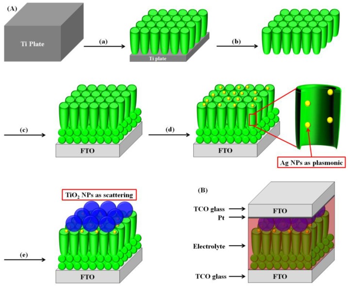
Figure 1 illustrates the fabrication of DSSCs with Ag NPs and large TiO2 NPs to enable plasmonic and scattering effects in open-ended freestanding TiO2 nanotube array–based DSSCs. Ti plates were anodized and then annealed at 500 °C for 1 h to prepare anatase TiO2 nanotube arrays. After carrying out secondary anodization, the TiO2 nanotube arrays were easily detached from the Ti plates. TiO2 nanotube arrays, once separated from the Ti plates, are termed “closed-ended freestanding TiO2 nanotube arrays”. Freestanding TiO2 nanotube arrays have a barrier layer at the bottom that disturbs electron transport and electrolyte diffusion. This barrier layer was removed using the ion-milling method with several minutes of Ar+ bombardment to yield “open-ended freestanding TiO2 nanotube arrays”. The closed- and open-ended freestanding TiO2 nanotube arrays were transferred to fluorine-doped tin oxide (FTO) glass using TiO2 paste and annealed to enhance the adhesion between the closed- and open-ended freestanding TiO2 nanotube arrays and the fluorine-doped tin oxide (FTO) glass. To improve the energy conversion efficiency by the plasmonic effect, Ag NPs were embedded in the channel of freestanding TiO2 nanotube arrays using 254 nm ultraviolet (UV) irradiation with aqueous silver nitrate. To further enhance the energy conversion efficiency, large TiO2 NPs (400 nm) as a scattering layer were coated onto the active layer by the doctor blade method. This substrate was sandwiched with the counter electrode and filled with electrolyte. The active area of the DSSCs was ~0.25 cm2.
Figure 1.
Overall scheme of dye-sensitized solar cells (DSSCs) with open-ended freestanding TiO2 nanotube arrays with Ag nanoparticles (NPs) and large TiO2 NPs. (A) (a) Ti anodization for TiO2 nanotube arrays; (b) freestanding TiO2 nanotube arrays and etching by ion milling; (c) transference of open-ended freestanding TiO2 nanotube arrays onto fluorine-doped tin oxide (FTO) glass; (d) formation of Ag NPs by ultraviolet (UV) irradiation; and (e) introduction of large TiO2 NPs. (B) Structure of a DSSC with freestanding TiO2 nanotube arrays and large TiO2 NPs.
2.2. Characterization of Freestanding TiO2 Nanotube Arrays with Channels Containing Ag NPs
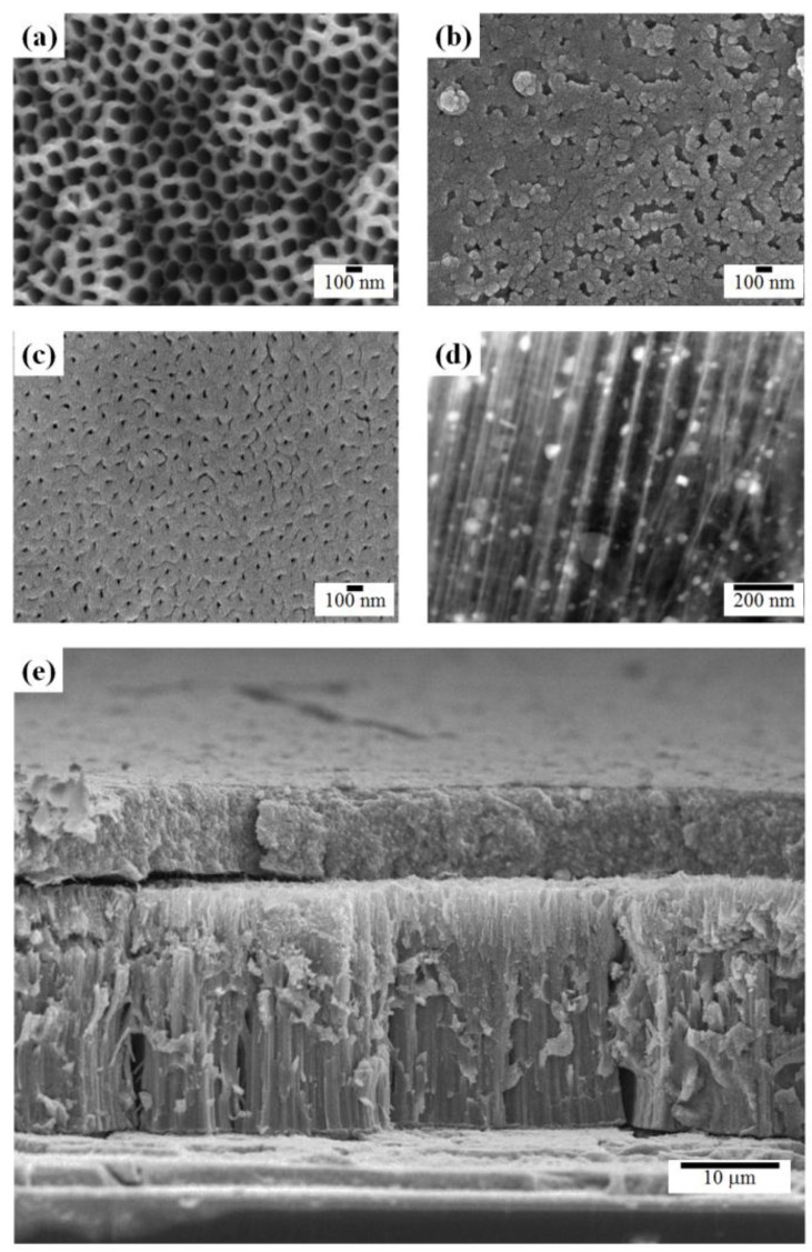
Field emission scanning electron microscope (FE-SEM) images of freestanding TiO2 nanotube (TNT) arrays are shown in Figure 2. The top side of the freestanding TiO2 nanotube arrays had 100-nm-diameter pores, as shown in Figure 2a. The bottom layer of closed-ended freestanding TiO2 nanotube arrays before ion milling lacked pores, as shown in Figure 2b. However, after ion milling, 20-nm-diameter pores were evident on the bottom layer of open-ended freestanding TiO2 nanotube arrays, as shown in Figure 2c. Open-ended TNT arrays can be prepared by chemical etching [35] or physical etching [33,36]. In the chemical etching method, the bottom layers of TNT arrays were easily removed by the etchant. However, the surface morphology and length of TNT arrays were also dissolved in etchant and TNT arrays are fragile when they are attached to a substrate because of their amorphous crystallinity. In the physical etching method, the bottom layer of TNT arrays was removed by the plasma or ion milling process, which is not simple. However, the surface morphology and length of TNT arrays are not damaged in the process and they are very stable when they are attached to a substrate because TNT arrays have the ability to change crystallinity from the amorphous to the anatase phase. After UV irradiation using a silver source, ~30 nm Ag NPs were seen in the channels of freestanding TiO2 nanotubes in high-angle annular dark-field (HAADF) images, as shown in Figure 2d. The length of the TiO2 nanotubes was ~22 µm and the length of the scattering layer, which consisted of 400 nm TiO2 NPs, was ~10 µm.
Figure 2.
Field emission scanning electron microscope (FE-SEM) images of the (a) top, (b) bottom, and (c) bottom of post–ion milling freestanding TiO2 nanotube arrays; (d) a high-angle annular dark-field (HAADF) image of Ag NPs in the channel of TiO2 nanotube arrays; and (e) a side view of the active layer with freestanding TiO2 nanotube arrays and a scattering layer.
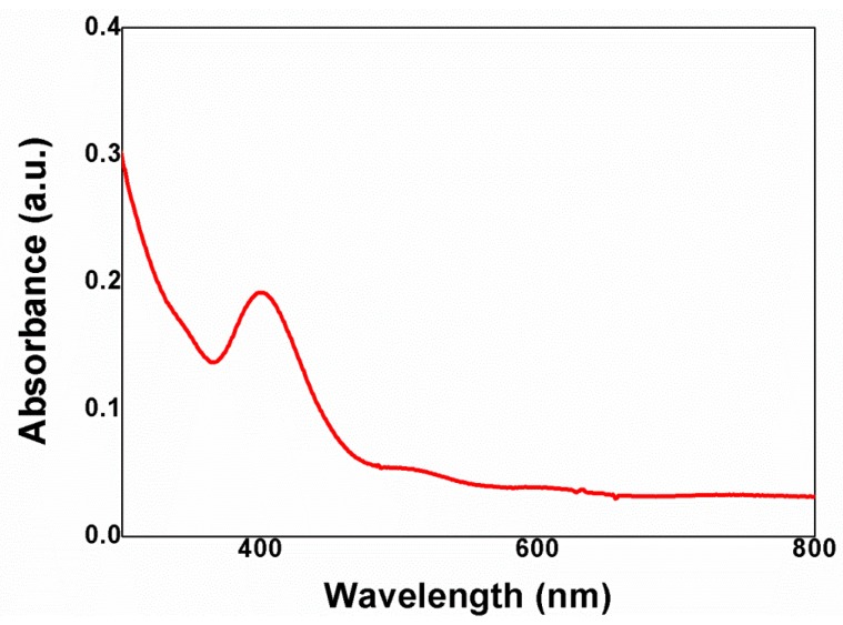
The ultraviolet-visible (UV-vis) spectrum of Ag NPs in the channels of freestanding TiO2 nanotubes is shown in Figure 3. A broad absorption peak centered at 402 nm was observed. The value is different from what it would be in the general solution phase, which is a 420 nm UV absorbance from 30 nm Ag NPs. This discrepancy may stem from different synthesis and measurement conditions used in this study [37,38,39]; the Ag NPs were synthesized by UV irradiation (at 254 nm) without adding a stabilizer and the Ag NPs were measured under dry conditions. The absorption band of Ag NPs is matched with the dye. cis-diisothiocyanato-bis(2,2’-bipyridyl-4,4’-dicarboxylato) ruthenium(II) bis(tetrabutylammonium) (N719) has two visible absorption bands, 390 nm and 531 nm, [40] that were affected by the plasmon band. Moreover, the shell of Ag NPs was prepared with TiCl4 to prevent the trapping of electrons by Ag NPs and to enable better electron transport in the channel of the TiO2 nanotube arrays.
Figure 3.
Ultraviolet-visible (UV-vis) spectrum of Ag NP-functionalized TiO2 nanotubes.
2.3. DSSCs with Closed-Ended Freestanding TiO2 Nanotube Arrays with Channels Containing Ag NPs and Large TiO2 NPs
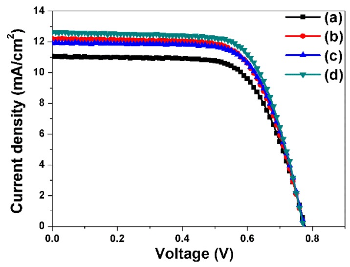
The photocurrent-voltage curves of DSSCs fabricated using closed-ended freestanding TiO2 nanotube arrays measured under air mass 1.5 illumination (100 mW/cm2) are shown in Figure 4 and Table 1. Four types of closed-ended freestanding TiO2 nanotube array–based DSSCs were fabricated in order to assess the effect of each component on the energy conversion efficiency: closed-ended freestanding TiO2 nanotube array–based DSSCs without Ag or large TiO2 NPs (a), with Ag NPs (b), with large TiO2 NPs (c), and with both Ag NPs and large TiO2 NPs (d). The open-circuit voltage (Voc), short-circuit current (Jsc), fill factor (ff), and energy conversion efficiency (η) values are shown in Table 1. The energy conversion efficiency of DSSCs based on closed-ended freestanding TiO2 nanotube arrays lacking NPs was 5.86%. The energy conversion efficiencies of DSSCs based on closed-ended freestanding TiO2 nanotube arrays with Ag NPs, with large TiO2 NPs, and with both Ag NPs and large TiO2 NPs were 6.40%, 6.24%, and 6.71%, respectively. The introduction of Ag NPs increased the energy conversion efficiency significantly, by 9.21% (actual efficiency change, from 5.86% to 6.40%) compared to closed-ended freestanding TiO2 nanotube array–based DSSCs without Ag and large TiO2 NPs, because of increased light harvesting by the plasmonic effect. The introduction of large TiO2 NPs also increased the energy conversion efficiency significantly, by 6.48% (actual efficiency, from 5.86% to 6.24%), owing to increased light harvesting by the scattering effect. Moreover, the introduction of both Ag NPs and large TiO2 NPs increased the energy conversion efficiency significantly, by 14.50% (actual efficiency, from 5.86% to 6.71%), because of increased light harvesting resulting from both the plasmonic and scattering effects.
Figure 4.
I–V curves of DSSC-based closed-ended freestanding TiO2 nanotube arrays fabricated without NPs (a), with Ag NPs (b), with large TiO2 NPs (c), and with Ag NPs and large TiO2 NPs (d).
Table 1.
Photovoltaic properties of dye-sensitized solar cells (DSSCs) based on closed-ended freestanding TiO2 nanotube arrays.
| DSSCs | Jsc (mA/cm2) | Voc (V) | ff | η (%) |
|---|---|---|---|---|
| (a) Closed-ended freestanding TiO2 nanotube arrays without any NPs | 11.05 | 0.78 | 0.68 | 5.86 |
| (b) Closed-ended freestanding TiO2 nanotube arrays with Ag NPs | 12.22 | 0.77 | 0.68 | 6.40 |
| (c) Closed-ended freestanding TiO2 nanotube arrays with large TiO2 NPs | 11.90 | 0.76 | 0.69 | 6.24 |
| (d) Closed-ended freestanding TiO2 nanotube arrays with Ag NPs and large TiO2 NPs | 12.63 | 0.77 | 0.69 | 6.71 |
2.4. DSSCs with Open-Ended Freestanding TiO2 Nanotube Arrays with Channels Containing Ag NPs and Large TiO2 NPs
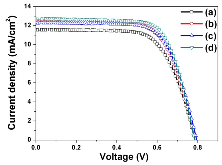
The photocurrent-voltage curves of DSSCs fabricated using open-ended freestanding TiO2 nanotube arrays are shown in Figure 5 and Table 2; they are useful in assessing the effect of each component on the energy conversion efficiency. Four types of DSSCs based on open-ended freestanding TiO2 nanotube arrays were fabricated: open-ended freestanding TiO2 nanotube array–based DSSCs without Ag or large TiO2 NPs (a), with Ag NPs (b), with large TiO2 NPs (c), and with both Ag NPs and large TiO2 NPs (d). The Voc, Jsc, ff, and η values are summarized in Table 2. The energy conversion efficiency of DSSCs based on open-ended freestanding TiO2 nanotube arrays lacking NPs was 6.12%. The energy conversion efficiencies of DSSCs based on open-ended freestanding TiO2 nanotube arrays with Ag NPs, with large TiO2 NPs, and with both Ag NPs and large TiO2 NPs were 6.68%, 6.62%, and 7.05%, respectively. The introduction of Ag NPs, large TiO2 NPs, and both increased the energy conversion efficiency by 9.15%, 8.17%, and 15.20%, respectively. Compared to closed-ended freestanding TiO2 nanotube arrays, the energy conversion efficiency of DSSCs based on open-ended freestanding TiO2 nanotube arrays was 5.07% (6.71%–7.05%) higher due to enhanced electron transport and electrolyte diffusion [33].
Figure 5.
I–V curves of DSSCs based on open-ended freestanding TiO2 nanotube arrays fabricated without NPs (a), with Ag NPs (b), with large TiO2 NPs (c), and with both Ag NPs and large TiO2 NPs (d).
Table 2.
Photovoltaic properties of DSSCs based on open-ended freestanding TiO2 nanotube arrays.
| ADSSCs | Jsc (mA/cm2) | Voc (V) | ff | η (%) |
|---|---|---|---|---|
| (a) Open-ended freestanding TiO2 nanotube arrays without any NPs | 11.56 | 0.79 | 0.67 | 6.12 |
| (b) Open-ended freestanding TiO2 nanotube arrays with Ag NPs | 12.45 | 0.79 | 0.68 | 6.68 |
| (c) Open-ended freestanding TiO2 nanotube arrays with large TiO2 NPs | 12.33 | 0.79 | 0.68 | 6.62 |
| (d) Open-ended freestanding TiO2 nanotube arrays with Ag NPs and large TiO2 NPs | 12.74 | 0.78 | 0.71 | 7.05 |
Although TiO2 nanotube array-based DSSCs have great potential, as far as we know, the theoretical maximum improvement by Ag NPs or a TiO2 scattering layer of TiO2 nanotube-based DSSCs has not yet been reported. However, the open-ended TiO2 nanotube-based devices exhibited an increase in one-sun efficiency from 5.3% to 9.1%, corresponding to a 70% increase, which is a much higher increase than we achieved [35]. We believe that there is ample room to improve efficiency by combining each parameter in an optimal condition based on theoretical studies.
3. Materials and Methods
3.1. Materials
Titanium plates (99.7% purity, 0.25 mm thickness, Alfa Aesar, Ward Hill, MA, USA), ammonium fluoride (NH4F, Showa Chemical Industry Co., Beijing, China, 97.0%), ethylene glycol (Daejung Chemical, Siheung, Korea, 99%), hydrogen peroxide (H2O2, Daejung Chemical, Siheung, Korea, 30%), fluorine-doped tin oxide (FTO) glass (Pilkington, St. Helens, UK, TEC-A7), titanium diisopropoxide bis(acetylacetonate) solution (Aldrich, St. Louis, MS, USA, 75 wt % in isopropanol), n-butanol (Daejung Chemical, Siheung, Korea, 99%), TiO2 paste (Ti-Nanoxide T/SP, Solaronix, Aubonne, Switzerland), scattering TiO2 paste (18NR-AO, Dyesol, Queanbeyan, Australia), silver nitrate (AgNO3, Aldrich, St. Louis, MS, USA, 99%), titanium chloride (TiCl4, Aldrich, St. Louis, MS, USA, 0.09 M in 20% HCl), dye (cis-diisothiocyanato-bis(2,2’-bipyridyl-4,4’-dicarboxylato) ruthenium(II) bis(tetrabutylammonium) (N719, Solaronix, Aubonne, Switzerland), chloroplatinic acid hexahydrate (H2PtCl6·6H2O, Aldrich, St. Louis, MS, USA), 1-butyl-3-methyl-imidazolium iodide (BMII, Aldrich, St. Louis, MS, USA, 99%), iodine (I2, Aldrich, St. Louis, MS, USA, 99%), guanidium thiocyanate (GSCN, Aldrich, St. Louis, MS, USA, 99%), 4-tertbutylpyridine (TBP, Aldrich, St. Louis, MS, USA, 96%), acetonitrile (CH3CN, Aldrich, St. Louis, MS, USA, 99.8%), and valeronitrile (CH3(CH2)3CN, Aldrich, St. Louis, MS, USA, 99.5%) were obtained from commercial manufacturers.
3.2. Preparation of Freestanding TiO2 Nanotube Arrays
TiO2 nanotube arrays were prepared by anodization of thin Ti plates. Ti anodization was carried out in an electrolyte composed of 0.8 wt % NH4F and 2 vol % H2O in ethylene glycol at 25 °C and at a constant voltage of 60 V direct current (DC) for 2 h. After being anodized, the Ti plates were annealed at 500 °C for 1 h under ambient conditions to improve the crystallinity of the TiO2 nanotube arrays, and then a secondary anodization was conducted at a constant voltage of 30 V DC for 10 min. The Ti plates were immersed in 10% H2O2 solution for several hours in order to detach the TiO2 nanotube arrays from the Ti plates and produce freestanding TiO2 nanotube arrays. The bottom of the TiO2 nanotube arrays was removed by ion milling with Ar+ bombardment for several minutes in order to prepare open-ended freestanding TiO2 nanotube arrays.
3.3. Preparation of Ag NPs in the Channel of Freestanding TiO2 Nanotube Arrays
A TiO2 blocking layer was formed on FTO glass by spin-coating with 5 wt % titanium di-isopropoxide bis(acetylacetonate) in butanol, followed by annealing at 500 °C for 1 h under ambient conditions to induce crystallinity. A TiO2 paste was coated onto the TiO2 blocking/FTO glass using the doctor blade method, and closed- and open-ended freestanding TiO2 nanotube arrays were then introduced onto the TiO2 paste. The substrate was annealed at 500 °C for 1 h under ambient conditions to enhance the adhesion between the TiO2 NPs and freestanding TiO2 nanotube arrays. The substrate was dipped in 0.3 mM AgNO3 aqueous solution and exposed to 254 nm UV irradiation. The substrate was treated with 10 mM TiCl4 solution at 50 °C for 30 min and then annealed at 500 °C for 1 h.
3.4. Fabrication of DSSCs with Freestanding TiO2 Nanotube Arrays with Channels Containing Ag NPs
A substrate that consisted of freestanding TiO2 nanotube arrays with channels containing Ag NPs was coated with ~400 nm TiO2 NPs for scattering and then annealed at 500 °C for 1 h under ambient conditions to induce crystallinity and adhesion. The substrate was immersed in a dye solution at 50 °C for 8 h to function as a working electrode. The working electrode was sandwiched with a counter electrode, Pt on FTO glass, by a 60-μm-thick hot-melt sheet and filled with electrolyte solution composed of 0.7 M 1-butyl-3-methyl-imidazolium iodide (BMII), 0.03 M I2, 0.1 M guanidium thiocyanate (GSCN), and 0.5 M 4-tertbutylpyridine (TBP) in a mixture of acetonitrile and valeronitrile (85:15, v/v).
3.5. Instruments
The morphology, thickness, size, and presence of Ag NPs in the channels of freestanding TiO2 nanotube arrays were confirmed using a field emission scanning electron microscope (FE-SEM, JSM-6330F, JEOL Inc., Tokyo, Japan) and the high angular annular dark field (HAADF) technique with a scanning transmission electron microscope (TEM, JEM-2200FS, JEOL Inc., Tokyo, Japan). The current density−voltage (J−V) characteristics and the incident photon-to-current conversion efficiency (IPCE) of the DSSCs were measured using an electrometer (Keithley 2400, Keithley Instruments, Inc., Cleveland, OH, USA) under AM 1.5 illumination (100 mW/cm2) provided by a solar simulator (1 kW xenon with AM 1.5 filter, PEC-L01, Peccell Technologies, Inc., Yokohama, Kanagawa, Japan), or using a solar cell IPCE measurement System(K3100, McScience Inc., Suwon, Korea) with reference to the calibrated diode.
4. Conclusions
In this study, we compared the natural consequences of altering three parameters, the plasmonic effect, the scattering effect, and open- vs. closed-ended freestanding TiO2 nanotubes, as a basic means of exploring improvements in efficiency. We demonstrated that the plasmonic and scattering effects enhanced the energy conversion efficiency of freestanding TiO2 nanotube arrays in DSSCs. Ag NPs were added to the channels of TiO2 nanotube arrays by UV irradiation to induce a plasmonic effect, and large TiO2 NPs were introduced to TiO2 nanotube arrays to induce a scattering effect. The energy conversion efficiency of DSSCs with both Ag NPs and large TiO2 NPs was higher than that of DSSCs without Ag NPs owing to the plasmonic effect, and it was higher than that of DSSCs without large TiO2 NPs owing to the scattering effect. Compared to closed-ended freestanding TiO2 nanotube arrays, open-ended freestanding TiO2 nanotube arrays [40] exhibited enhanced energy conversion efficiency. We demonstrate that Ag NPs, TiO2 NPs, and open-ended freestanding TiO2 nanotube arrays enhanced the energy conversion efficiency; furthermore, the combination of all components exhibited the highest energy conversion efficiency. Our research suggests that the energy conversion efficiency of DSSCs is improved by both the plasmonic and scattering effects. This knowledge has applications in organic solar cells, hybrid solar cells, and perovskite solar cells.
Author Contributions
Won-Yeop Rho, Myeung-Hwan Chun, Jung Sang Suh and Bong-Hyun Jun designed the research and wrote the manuscript. Won-Yeop Rho, Ho-Sub Kim and Hyung-Mo Kim carried out experiments. All authors discussed the results and commented on the manuscript. Won-Yeop Rho and Bong-Hyun Jun guided all aspects of the work.
Conflicts of Interest
The authors declare no conflict of interest.
References
- 1.Oregan B., Gratzel M. A low-cost, high-efficiency solar-cell based on dye-sensitized colloidal TiO2 films. Nature. 1991;353:737–740. doi: 10.1038/353737a0. [DOI] [Google Scholar]
- 2.Lim J., Kim H.A., Kim B.H., Han C.H., Jun Y. Reversely fabricated dye-sensitized solar cells. RSC Adv. 2014;4:243–247. doi: 10.1039/C3RA45507F. [DOI] [Google Scholar]
- 3.Jo Y., Yun Y.J., Khan M.A., Jun Y. Densely packed setose ZnO nanorod arrays for dye sensitized solar cells. Synth. Met. 2014;198:137–141. doi: 10.1016/j.synthmet.2014.10.013. [DOI] [Google Scholar]
- 4.Kim J., Lim J., Kim M., Lee H.S., Jun Y., Kim D. Fabrication of carbon-coated silicon nanowires and their application in dye-sensitized solar cells. ACS Appl. Mater. Interfaces. 2014;6:18788–18794. doi: 10.1021/am504469y. [DOI] [PubMed] [Google Scholar]
- 5.Ko K.W., Lee M., Sekhon S., Balasingam S.K., Han C.H., Jun Y. Efficiency enhancement of dye-sensitized solar cells by the addition of an oxidizing agent to the TiO2 paste. Chem. Sus. Chem. 2013;6:2117–2123. doi: 10.1002/cssc.201300280. [DOI] [PubMed] [Google Scholar]
- 6.Balasingam S.K., Kang M.G., Jun Y. Metal substrate based electrodes for flexible dye-sensitized solar cells: Fabrication methods, progress and challenges. Chem. Commun. 2013;49:11457–11475. doi: 10.1039/c3cc46224b. [DOI] [PubMed] [Google Scholar]
- 7.Jung C.-L., Lim J., Park J.-H., Kim K.-H., Han C.-H., Jun Y. High performance dye sensitized solar cells by adding titanate co-adsorbant. RSC Adv. 2013;3:20488–20491. doi: 10.1039/c3ra42907e. [DOI] [Google Scholar]
- 8.Nath N.C.D., Ahammad A., Sarker S., Rahman M., Lim S.-S., Choi W.-Y., Lee J.-J. Carbon nanotubes on fluorine-doped tin oxide for fabrication of dye-sensitized solar cells at low temperature condition. J. Nanosci. Nanotechnol. 2012;12:5373–5380. doi: 10.1166/jnn.2012.6413. [DOI] [PubMed] [Google Scholar]
- 9.Deb Nath N.C., Lee H.J., Choi W.-Y., Lee J.-J. Effects of phenylalkanoic acids as co-adsorbents on the performance of dye-sensitized solar cells. J. Nanosci. Nanotechnol. 2013;13:7880–7885. doi: 10.1166/jnn.2013.8117. [DOI] [PubMed] [Google Scholar]
- 10.Grätzel M. Dye-sensitized solar cells. J. Photochem. Photobiol. C. 2003;4:145–153. doi: 10.1016/S1389-5567(03)00026-1. [DOI] [Google Scholar]
- 11.Du L.C., Furube A., Hara K., Katoh R., Tachiya M. Mechanism of particle size effect on electron injection efficiency in ruthenium dye-sensitized TiO2 nanoparticle films. J. Phys. Chem. C. 2010;114:8135–8143. doi: 10.1021/jp911418g. [DOI] [Google Scholar]
- 12.Ahn J., Lee K.C., Kim D., Lee C., Lee S., Cho D.W., Kyung S., Im C. Synthesis of novel ruthenium dyes with thiophene or thienothiophene substituted terpyridyl ligands and their characterization. Mol. Cryst. Liquid Cryst. 2013;581:45–51. doi: 10.1080/15421406.2013.808147. [DOI] [Google Scholar]
- 13.Kwon T.H., Kim K., Park S.H., Annamalai A., Lee M.J. Effect of seed particle size and ammonia concentration on the growth of ZnO nanowire arrays and their photoconversion efficiency. Int. J. Nanotechnol. 2013;10:681–691. doi: 10.1504/IJNT.2013.054210. [DOI] [Google Scholar]
- 14.Rho W.-Y., Kim H.-S., Lee S.H., Jung S., Suh J.S., Hahn Y.-B., Jun B.-H. Front-illuminated dye-sensitized solar cells with Ag nanoparticle-functionalized freestanding TiO2 nanotube arrays. Chem. Phys. Lett. 2014;614:78–81. doi: 10.1016/j.cplett.2014.09.013. [DOI] [Google Scholar]
- 15.Hwang K.-J., Cho D.W., Lee J.-W., Im C. Preparation of nanoporous TiO2 electrodes using different mesostructured silica templates and improvement of the photovoltaic properties of DSSCs. New J. Chem. 2012;36:2094–2100. doi: 10.1039/c2nj40547d. [DOI] [Google Scholar]
- 16.Nath N.C.D., Kim J.C., Kim K.P., Yim S., Lee J.-J. Deprotonation of N3 adsorbed on TiO2 for high-performance dye-sensitized solar cells (DSSCs) J. Mater. Chem. A. 2013;1:13439–13442. doi: 10.1039/c3ta12298k. [DOI] [Google Scholar]
- 17.Nakade S., Saito Y., Kubo W., Kitamura T., Wada Y., Yanagida S. Influence of TiO2 nanoparticle size on electron diffusion and recombination in dye-sensitized TiO2 solar cells. J. Phys. Chem. B. 2003;107:8607–8611. doi: 10.1021/jp034773w. [DOI] [Google Scholar]
- 18.Zhu K., Kopidakis N., Neale N.R., van de Lagemaat J., Frank A.J. Influence of surface area on charge transport and recombination in dye-sensitized TiO2 solar cells. J. Phys. Chem. B. 2006;110:25174–25180. doi: 10.1021/jp065284+. [DOI] [PubMed] [Google Scholar]
- 19.Chung K.-H., Rahman M.M., Son H.-S., Lee J.-J. Development of well-aligned TiO2 nanotube arrays to improve electron transport in dye-sensitized solar cells. Int. J. Photoenergy. 2012;2012 doi: 10.1155/2012/215802. [DOI] [Google Scholar]
- 20.Lee G.I., Nath N.C.D., Sarker S., Shin W.H., Ahammad A.S., Kang J.K., Lee J.-J. Fermi energy level tuning for high performance dye sensitized solar cells using sp 2 selective nitrogen-doped carbon nanotube channels. Phys. Chem. Chem. Phys. 2012;14:5255–5259. doi: 10.1039/c2cp40279c. [DOI] [PubMed] [Google Scholar]
- 21.Nath N.C.D., Sarker S., Ahammad A.S., Lee J.-J. Spatial arrangement of carbon nanotubes in TiO2 photoelectrodes to enhance the efficiency of dye-sensitized solar cells. Phys. Chem. Chem. Phys. 2012;14:4333–4338. doi: 10.1039/c2cp00035k. [DOI] [PubMed] [Google Scholar]
- 22.Yadav S.K., Madeshwaran S.R., Cho J.W. Synthesis of a hybrid assembly composed of titanium dioxide nanoparticles and thin multi-walled carbon nanotubes using “click chemistry”. J. Colloid Interface Sci. 2011;358:471–476. doi: 10.1016/j.jcis.2011.03.040. [DOI] [PubMed] [Google Scholar]
- 23.Bavykin D.V., Parmon V.N., Lapkin A.A., Walsh F.C. The effect of hydrothermal conditions on the mesoporous structure of TiO2 nanotubes. J. Mater. Chem. 2004;14:3370–3377. doi: 10.1039/b406378c. [DOI] [Google Scholar]
- 24.Macak J.M., Tsuchiya H., Schmuki P. High-aspect-ratio TiO2 nanotubes by anodization of titanium. Angew. Chem. Int. Ed. Engl. 2005;44:2100–2102. doi: 10.1002/anie.200462459. [DOI] [PubMed] [Google Scholar]
- 25.Law M., Greene L.E., Johnson J.C., Saykally R., Yang P. Nanowire dye-sensitized solar cells. Nat. Mater. 2005;4:455–459. doi: 10.1038/nmat1387. [DOI] [PubMed] [Google Scholar]
- 26.Mor G.K., Varghese O.K., Paulose M., Shankar K., Grimes C.A. A review on highly ordered, vertically oriented TiO2 nanotube arrays: Fabrication, material properties, and solar energy applications. Sol. Energy Mater. Sol. Cells. 2006;90:2011–2075. doi: 10.1016/j.solmat.2006.04.007. [DOI] [Google Scholar]
- 27.Jennings J.R., Ghicov A., Peter L.M., Schmuki P., Walker A.B. Dye-sensitized solar cells based on oriented TiO2 nanotube arrays: Transport, trapping, and transfer of electrons. J. Am. Chem. Soc. 2008;130:13364–13372. doi: 10.1021/ja804852z. [DOI] [PubMed] [Google Scholar]
- 28.Rho W.-Y., Jeon H., Kim H.-S., Chung W.-J., Suh J.S., Jun B.-H. Recent progress in dye-sensitized solar cells for improving efficiency: TiO2 nanotube arrays in active layer. J. Nanomater. 2015;2015 doi: 10.1155/2015/247689. [DOI] [Google Scholar]
- 29.Atwater H.A., Polman A. Plasmonics for improved photovoltaic devices. Nat. Mater. 2010;9:865–865. doi: 10.1038/nmat2866. [DOI] [PubMed] [Google Scholar]
- 30.Standridge S.D., Schatz G.C., Hupp J.T. Distance dependence of plasmon-enhanced photocurrent in dye-sensitized solar cells. J. Am. Chem. Soc. 2009;131:8407–8409. doi: 10.1021/ja9022072. [DOI] [PubMed] [Google Scholar]
- 31.Brown M.D., Suteewong T., Kumar R.S.S., D’Innocenzo V., Petrozza A., Lee M.M., Wiesner U., Snaith H.J. Plasmonic dye-sensitized solar cells using core-shell metal-insulator nanoparticles. Nano Lett. 2011;11:438–445. doi: 10.1021/nl1031106. [DOI] [PubMed] [Google Scholar]
- 32.Qi J.F., Dang X.N., Hammond P.T., Belcher A.M. Highly efficient plasmon-enhanced dye-sensitized solar cells through metal@oxide core-shell nanostructure. ACS Nano. 2011;5:7108–7116. doi: 10.1021/nn201808g. [DOI] [PubMed] [Google Scholar]
- 33.Rho C., Min J.H., Suh J.S. Barrier layer effect on the electron transport of the dye-sensitized solar cells based on TiO2 nanotube arrays. J. Phys. Chem. C. 2012;116:7213–7218. doi: 10.1021/jp211708y. [DOI] [Google Scholar]
- 34.Rho W.-Y., Chun M.-H., Kim H.-S., Hahn Y.-B., Suh J.S., Jun B.-H. Improved energy conversion efficiency of dye-sensitized solar cells fabricated using open-ended TiO2 nanotube arrays with scattering layer. Bull. Korean Chem. Soc. 2014;35 doi: 10.5012/bkcs.2014.35.4.1165. [DOI] [Google Scholar]
- 35.Lin C.-J., Yu W.-Y., Chien S.-H. Transparent electrodes of ordered opened-end TiO2-nanotube arrays for highly efficient dye-sensitized solar cells. J. Mater. Chem. 2010;20:1073–1077. doi: 10.1039/B917886D. [DOI] [Google Scholar]
- 36.Li L.-L., Chen Y.-J., Wu H.-P., Wang N.S., Diau E.W.-G. Detachment and transfer of ordered TiO2 nanotube arrays for front-illuminated dye-sensitized solar cells. Energy Environ. Sci. 2011;4:3420–3425. doi: 10.1039/c0ee00474j. [DOI] [Google Scholar]
- 37.Hahm E., Jeong D., Cha M.G., Choi J.M., Pham X.-H., Kim H.-M., Kim H., Lee Y.-S., Jeong D.H., Jung S. β-CD dimer-immobilized Ag assembly embedded silica nanoparticles for sensitive detection of polycyclic aromatic hydrocarbons. Sci. Rep. 2016;6 doi: 10.1038/srep26082. [DOI] [PMC free article] [PubMed] [Google Scholar]
- 38.Arockia Jency D., Umadevi M., Sathe G. Sers detection of polychlorinated biphenyls using β-cyclodextrin functionalized gold nanoparticles on agriculture land soil. J. Raman Spectrosc. 2015;46:377–383. doi: 10.1002/jrs.4654. [DOI] [Google Scholar]
- 39.Xie Y., Wang X., Han X., Xue X., Ji W., Qi Z., Liu J., Zhao B., Ozaki Y. Sensing of polycyclic aromatic hydrocarbons with cyclodextrin inclusion complexes on silver nanoparticles by surface-enhanced Raman scattering. Analyst. 2010;135:1389–1394. doi: 10.1039/c0an00076k. [DOI] [PubMed] [Google Scholar]
- 40.Kim H.-Y., Rho W.-Y., Lee H.Y., Park Y.S., Suh J.S. Aggregation effect of silver nanoparticles on the energy conversion efficiency of the surface plasmon-enhanced dye-sensitized solar cells. Sol. Energy. 2014;109:61–69. doi: 10.1016/j.solener.2014.08.019. [DOI] [Google Scholar]


