Abstract
This paper presents the design, modeling, and control of a meso-scale torsion actuator based on shape memory alloy (SMA) for image-guided surgical procedures. Developing a miniature torsion actuator is challenging, but it opens the possibility of significantly enhancing the robot agility and maneuverability. The proposed torsion actuator is bi-directionally actuated by a pair of antagonistic SMA torsion springs through alternate Joule heating and natural cooling. The torsion actuator is integrated into a surgical robot prototype to demonstrate its working performance in the humid environment under C-Arm CT image guidance.
Index Terms: Torsion actuator, shape memory alloy, meso-scale robot, maximum motion range, control, CT imaging
I. Introduction
Many macro-scale articulated robots have adopted electromagnetic motors to achieve high agility by the integration of torsion and bending joints [1]–[6]. In micro-scale mechatronic systems, torsion joints have been used to rotate mirrors and control light transmission [7]. However, meso-scale surgical robots mostly use bending and translation joints, and torsion joints are rarely adopted. For instance, SMA wires [8], [9] and tendon driven mechanisms [10] have been used to actuate the bending joints of surgical robots. This is because conventional actuators, such as electromagnetic, hydraulic, and pneumatic actuators, are difficult to be miniaturized and the techniques of etching and micromachining [11] are infeasible for meso-scale systems. Besides, it is difficult to design miniature tendon driven mechanisms for torsion joints due to limited space and SMA wires are inappropriate to actuate torsion joints. Therefore, smart materials, such as piezoelectric ceramics (PZT) and various SMA forms, have been researched to develop meso-scale torsion actuators for surgical robots.
The PZT micromotors (around 10 mm or less in diameter) can be promising for meso-scale torsion joints because of their small dimensions, but their torque capacity could pose a limitation [12], [13]. On the other hand, the pre-deformed SMA can generate a large recovery force when it is heated and it has been proved that the SMA-based bending joints are capable of moving within phantom tissue [14]. Besides, the low cost of SMA makes it possible to develop a disposable device for surgical procedures. Several small rotary actuators have been developed by using SMA wires [15]–[17], but none has been applied in the meso-scale robots, probably due to their relatively large dimensions. Therefore, our objective is to develop a meso-scale SMA-based actuator for the torsion joint of a surgical robot.
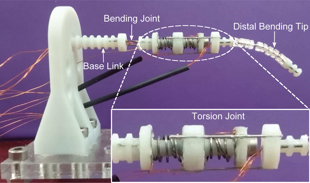
Considering that a deformed torsion spring can directly generate a rotary motion by fixing one end of the spring and releasing the other end, a one-way rotary actuator can be developed based on an SMA torsion spring. When a pre-tightened SMA torsion spring is heated above the transformation temperature, it will return to its memorized configuration and a rotary motion can be generated. Since the SMA torsion spring works by changing the diameter of the spring coils rather than the length of the spring wire [15]–[17], much fewer spring turns are needed and a more compact design can be realized. Our research adopts a pair of antagonistic SMA torsion springs to develop a meso-scale bi-directional rotary actuator for torsion joints. Fig. 1 shows a meso-scale surgical robot prototype with the SMA-based torsion actuator installed before the distal bending tip. Tip articulation of the robot can be realized by integrating the actuation of the torsion joint and the bending tip. This design can be applied to improve the outcomes of neurosurgical intracerebral hemorrhage evacuation (NICHE), since tip articulation allows the robot to achieve a larger workspace without any significant disruption to healthy brain tissue than traditional devices made of straight endoscopes [18], [19].
Fig. 1.
Meso-scale surgical robot prototype with three DoFs including a bending joint, a torsion joint, and a distal bending tip.
To realize tip articulation, another robotic system was developed by J. Burgner et al. using a pre-curved superelastic inner tube and a straight and stiff outer tube [20]. By rotating the inner tube and inserting and retracting both tubes, tip articulation was realized in a simulated hemorrhage [20]. In our prior works, we have proposed an SMA-based torsion actuator and conducted preliminary studies on the SMA torsion spring [21]. We have also derived the system model and conducted performance evaluation tests on the actuator [22]. Based on the derived model, a series of experiments have been conducted to characterize the model parameters [23]. Compared with our prior works, this paper provides more details in the analysis of the actuator motion and the demonstration of the actuator integrated with the robot prototype, to give a thorough insight into the developed meso-scale SMA-based torsion actuator. Note that the proximal bending joint of the robot is intended for fine positioning around the target vicinity and it is not used in this presented work. The SMA-based torsion actuator is installed close to the bending tip to reduce the rotary inertia coupled with the actuator.
The rest of this paper is organized as follows. In section II, the review of the working principle and the hardware development of the SMA-based torsion actuator is presented. In section III, the modeling of the SMA torsion spring and the torsion actuator are reviewed, followed by the analysis of the optimal spring pre-deformation for the maximum motion range based on the model. In section IV, the developed actuator is evaluated with a proposed double-channel model-based controller and the experimental results with detailed discussion are provided. In section V, the design of the torsion actuator is improved for hermetic packing, followed by the qualitative robot demonstration in the humid environment under C-Arm CT image guidance. Finally, we make some concluding remarks in section VI.
II. Fundamental of the Torsion Actuator
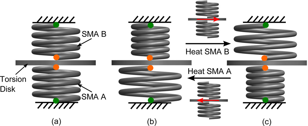
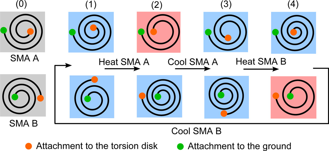
When an SMA torsion spring is heated, it tends to recover its memorized shape due to its internal crystal transformation from martensite phase (M) to austenite phase (A). Fig. 2 shows the working principle of the proposed torsion actuator. Two SMA torsion springs (SMA A and SMA B) with the same properties are coaxially fixed at the green points and connected to a torsion disk at the orange points. In case (a), both springs are pre-tightened by one turn. When SMA A or SMA B has recovered its memorized configuration after it is heated, the system status is shown in case (b) or (c), respectively. In case (b) or (c), when SMA B or SMA A is heated, it will start recovering its memorized configuration, thereby rotating the torsion disk counter-clockwise or clockwise (top view) and tightening the other spring. Since the SMA Young’s modulus is large at high temperatures, the immediate heating of the SMA spring after the heating process of the other one can hardly reverse the torsion disk. Therefore, a cooling process is necessary between alternate heating processes and natural cooling by ambient atmosphere is adopted. Similar to [23], Fig. 3 shows the schematic of the typical motion of the torsion actuator by heating and cooling SMA springs alternately. Status 0 shows that both springs are pre-tightened by half a turn in their initial configurations. The details of each status and motion process can be found in our prior works [21], [23].
Fig. 2.
Working principle of the SMA-based torsion actuator: (a) SMA A and SMA B are pre-tightened by one turn (initial configuration), (b) SMA A is in the recovered configuration (heated) and SMA B is unheated, and (c) SMA A is unheated and SMA B is in the recovered configuration (heated). The red arrows indicate the motion direction of the torsion disk.
Fig. 3.
A schematic of the motion process of the proposed torsion actuator with alternate Joule heating and natural cooling of SMA torsion springs. Status 0 denotes the initial configurations of unheated SMA A and SMA B and status 1 to 4 denotes the spring configurations when either spring is heated to high temperature or cooled to the room temperature.
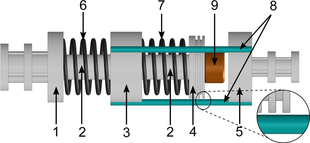
Fig. 4 shows the schematic diagram of the torsion actuator, which comprises of a shaft made of a metallic bolt, a base disk and a top disk fixed on the shaft, a torsion disk rotating around the shaft, and two SMA torsion springs fixed on the disks. Three supporting rods are connected between the torsion disk and an output disk to output the torque from the torsion disk. Two insulating sheaths are fixed on the shaft to constrain the position of the torsion disk and prevent short circuit. Grease is applied to reduce the friction torque applied on the torsion disk. By appropriately selecting the spring wire diameter and the coil pitch, the friction torque caused by the contact between the spring turns can be reduced. The base disk and output disk are connected to a bending joint and a distal bending tip made of SMA wires, respectively (see Fig. 1). Before assembly, both springs are pre-tightened by one and a half turns. The SMA torsion spring is developed by winding a 0.5 mm diameter nitinol wire (Dynalloy, Inc.) around a metallic bolt, followed by the heat treatment in a furnace and annealing inside icy water. In their natural configurations, both springs have five turns with a counter-clockwise winding shape. For each spring, the number of deformable turns is denoted as N0 and N0 is equal to three in our design, because the first and last turns are fixed on the disks. The details of design and fabrication can be found in our prior works [21], [23].
Fig. 4.
Mechanical design of the SMA-based torsion actuator including (1) base disk, (2) sheath, (3) torsion disk, (4) top disk, (5) output disk, (6) SMA A, (7) SMA B, (8) supporting rods, and (9) shaft (bolt, thread size: 4–40). All disks and sheaths are made of VeroWhite using an Objet 350V 3D printer.
III. Torsion Actuator Modeling
A. SMA Torsion Spring Model
Since the axial length of the SMA torsion spring is constant under the assumption of pure torsion, the shear strain is negligible due to the small axial pre-compression [23]. By considering each spring turn as a bending wire, the maximum normal strain (ε) of a bending spring turn is given by [22], [23]:
| (1) |
where , and d, Ls, and θ are the wire diameter, wire length, and torsion angle of the spring, respectively. For a torsion spring, the maximum normal stress (σ) caused by external torque (τ) is given by [22], [23]:
| (2) |
where and Kc is the stress-concentration factor approximately equal to one. To model the nonlinear characteristics of the SMA torsion spring, the Liang-Rogers model [24] is used, which has been proved to be capable of modeling SMA-based bending actuators in our group’s prior work [25]. By substituting (1) and (2) into the Liang-Rogers model, the constitutive model for the SMA torsion spring is given by [22], [23]:
| (3) |
where E, ξ, and θL denote the Young’s modulus, martensite volume fraction, and maximum recoverable torsion angle, respectively. The variables with subscript ‘0’ denote their initial states. Thermal expansion is neglected, because the strain change caused by thermal expansion is much smaller than that caused by phase transformation. By substituting (1) and (2) into the expressions for ξ in the Liang-Rogers model [24], ξ is rewritten for the SMA torsion spring as [22], [23]:
| (4) |
and
| (5) |
where T is the spring temperature, As and Af are the start and end temperatures for M→A, respectively, Ms and Mf are the start and end temperatures for A→M, respectively, and CA and CM are the coefficients representing the influence of stress on the transformation temperatures for these two processes, respectively. By substituting (1) and (2) into the expression of torsion spring stiffness (K = τ/θ), K can be rewritten as: K = C1E/C2. Considering that the value of E is a combination of Young’s modulus values in the entirely martensite phase (EM) and entirely austenite phase (EA) based on ξ if ε is smaller than a critical value , and E is constant (ES) if ε is larger than , the torsion stiffness can be written as [22], [23]:
| (6) |
where , KM = C1EM/C2, KA = C1EA/C2, and KS = C1ES/C2. is the critical strain that denotes the start of stress-induced martensite phase. More details of the modeling and characterization for the SMA torsion spring can be found in our prior works [22], [23].
B. Torsion Actuator Static Model
Each SMA torsion spring is positively deformed if it tightens, so the positive deformation directions for SMA A (θA) and SMA B (θB) are counter-clockwise and clockwise, respectively (see Fig. 3). Since the actuator outputs torque from the torsion disk, the counter-clockwise rotation of the torsion disk is defined as the positive motion of the actuator (θJ) in the world frame. The deformation angles of SMA A and SMA B satisfy the following angular constraint [22], [23]:
| (7) |
where θP is the summation of the pre-deformation angles of both springs. Since the torque of each SMA torsion spring points to its recovered configuration, the torque directions of SMA A and SMA B are always clockwise (negative) and counter-clockwise (positive), respectively (see Fig. 3). When SMA A and SMA B are balanced during the quasi-static motion of the actuator, we have the following torque constraint [22], [23]:
| (8) |
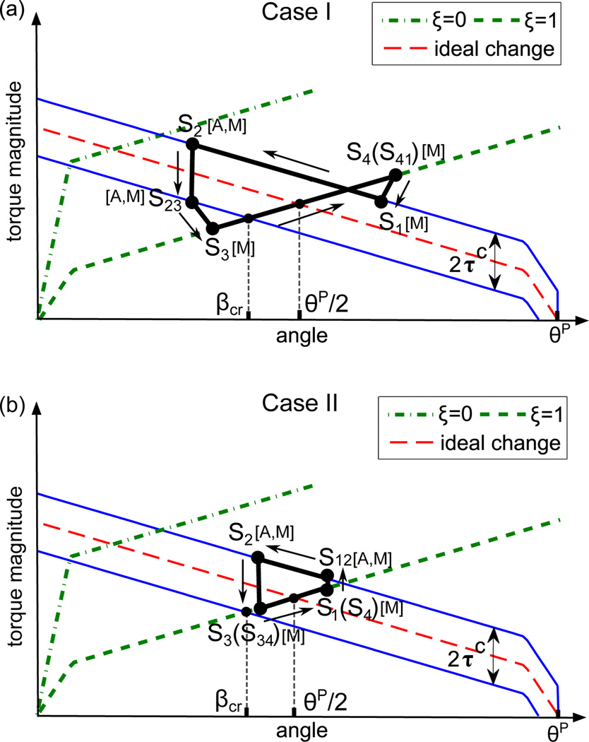
where τA and τB are the torque magnitudes of SMA A and SMA B, respectively. τf is the friction torque and it is assumed that τf = −τcsign(θ̇J) when the actuator moves, where τc is the magnitude of the critical torque for motion initiation. When the torsion disk is stationary, τf varies between ±τc. According to the angular and torque constraints, two conclusions can be drawn: 1) The angle of the heated spring is equal to the difference between θP and the angle of the unheated spring; 2) The torque magnitude of the heated spring is equal to the summation of the torque magnitude of the unheated spring and the friction torque. Therefore, two motion processes are summarized as shown in Fig. 5 based on the stiffness model for the SMA torsion spring (6). In Table I, each row shows the motion sequences of the SMA torsion springs and each column shows the simultaneous statuses of both springs.
Fig. 5.
A schematic of the motion process of SMA torsion springs when the spring angle at S2 is smaller (a) or larger (b) than βcr. The ideal change means the torque of the heated spring without the friction torque, and the upper and lower solid blue lines take friction into account when τf is equal to τc and −τc, respectively. [A,M] means that both austenite phase and martensite phase exist and [M] means that SMA is entirely in martensite phase.
TABLE I.
Status Sequence of SMA Torsion Springs
| Case I | 1 | 2 | 3 | 4 | 5 | 6 | 7 | … |
| SMA A | S1 | S2 | S23 | S3 | S4 | S41 | S1 | … |
| SMA B | S3 | S4 | S41 | S1 | S2 | S23 | S3 | … |
| Case II | 1 | 2 | 3 | 4 | 5 | 6 | 7 | … |
| SMA A | S1 | S12 | S2 | S3 | S34 | S4 | S1 | … |
| SMA B | S3 | S34 | S4 | S1 | S12 | S2 | S3 | … |
These two cases are differentiated by the following condition: the angle of the SMA torsion spring at S2 is smaller (case I) or larger (case II) than a critical angle (βcr). In case I, when the SMA torsion spring is heated from S1 to S2, the antagonistic spring is passively deformed from S3 to S4. In the cooling process from S2 to S3, the spring is stationary in the beginning due to the friction torque and starts moving at S23 when the the friction torque magnitude achieves τc. Meanwhile, the antagonistic spring is stationary from S4 to S41 with constant torque because of constant stiffness at the room temperature. From S41 to S1, the deformation of the antagonistic spring is relaxed to some extent. Therefore, the path inclinations from S1 to S2, S23 to S3, S3 to S4, S41 to S1 are equal to −ES, −EM, ES, and EM, respectively. In case II, when the spring is heated, it is stationary in the beginning due to the friction torque and starts moving at S12 when the friction torque magnitude achieves τc at S12, so the antagonistic spring is stationary from S3 to S34 and passively deformed from S34 to S4. When the spring is cooled, it is stationary in the whole cooling process due to the friction torque from S2 to S3. Meanwhile, the antagonistic spring is stationary from S4 to S1 and outputs constant torque. Therefore, the path inclinations from S12 to S2 and S34 to S4 are equal to −ES and ES, respectively.
A general physical parameter (P) for SMA A or SMA B at Si is denoted by PAi or PBi, respectively. Since both springs have identical properties, we focus on SMA A. In both the heating and cooling processes, the governing equation for SMA A is given by (3). In the heating process of case II, since SMA A is stationary until S12 and its martensite volume fraction is one at S1, the governing equation at S12 is given by [22], [23]:
| (9) |
where and τA12 are functions of θA1. By writing (9) into a quadratic form, ξA12 ∈ [0, 1] can be solved unless τc is too large. Since the friction torque is constant once SMA A starts moving, τA proportionally changes with θA. Based on the governing equation (3), θA from S1 to S2 in case I and from S12 to S2 in case II is solved as [22], [23]:
| (10) |
where is equal to one for the process from S1 to S2 in case I and ξA12 for the process from S12 to S2 in case II. Since EA is a function of ξA, which can be expressed by TA and τA as (4), and τA is dependent on θA based on (6), the nonlinear relationship between θA and TA can be obtained from (10). Although it is difficult to explicitly express θA as a function of TA, we can numerically solve TA with the reference of θA by computing the references of ξA and τA based on (10) and (6), and substituting them into (4). In the cooling process of case II, SMA A is stationary from S2 to S3, so we have θA = θA2. In the cooling process of case I, SMA A is stationary until S23, so the governing equation at S23 is rewritten to [22], [23]:
| (11) |
where and τA23 are functions of θA2, and can be obtained from (4) as the result of the previous heating process. By using the quadratic form of (11), ξA23 ∈ [0, 1] can be solved. After S23, SMA A starts moving with the constant friction torque. By using the approach similar to that in the heating process, θA from S23 to S3 in case I is solved as [22], [23]:
| (12) |
where is equal to ξA23 for the process from S23 to S3 in case I. Based on the reference of θA, we can numerically compute TA by using the model equations (4), (6), and (10). The critical angle βcr can be computed using the following geometric relationship in Fig. 5 when the deformation angle is equal to βcr [22], [23]:
| (13) |
which yields:
The other two processes for SMA A when SMA B is heated and cooled, which are S3 to S4 and S4 to S1, respectively, can be modeled based on the angular constraint (7) and the modeling results for SMA B. More details of the actuator modeling and the model validation by comparing the angular measurement with the model prediction can be found in our prior work [23].
C. Maximum Motion Range
The maximum motion range of a rotary actuator formed by a pair of antagonistic SMA wires is numerically solved based on the force balance between the actuated SMA wire and the load [26]. In this paper, we investigate the optimal pre-deformation of SMA torsion springs to realize the maximum motion range by using an analytic approach based on the derived model. The maximum motion range is affected by N0, θP, and τc, and our objective is to find the optimal θP under certain N0 and τc. When SMA A (SMA B) is at S2, the angle of SMA A (SMA B) is the minimum , and the angle of SMA B (SMA A) is the maximum . The motion range (Rg) is equal to the difference between and (or and ) and given by: . Due to the angular constraint (7) and the identity between SMA A and SMA B, Rg can be rewritten as:
| (14) |
Based on the derived model, different pre-deformations under certain N0 lead to three types of motion cycles with the full motion range as shown in Fig. 6. When the deformation angles of SMA A and SMA B are the minimum and maximum, respectively, the torque balance between SMA A at S2 and SMA B at S4 is given by:
| (15) |
where τA2 and τB4 are functions of for the three cases and given by:
| (16) |
and
| (17) |
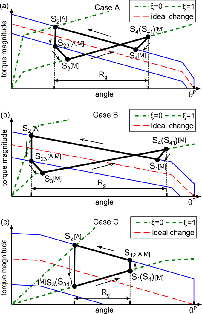
where case A: , case B: , and case C: . and are the critical values of θP to differentiate different cases. is the critical pre-deformation of the SMA torsion spring before any permanent deformation and is given by: , where is the critical strain approximately equal to 8% for low cycle use of SMA made of nitinol [27], which makes equal to 6.5π for the presented SMA torsion springs. Since each spring is pre-tightened by 2.5π, both springs are always in the safety region. By substituting (16) and (17) into (15), is solved and the motion range is given by:
| (18) |
Note that KM, KA, KS, and are functions of N0. By making the expression for case B equal to those for case A and case C, respectively, the critical pre-deformation can be solved as:
| (19) |
and
| (20) |
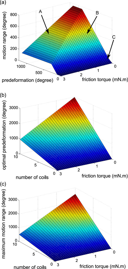
Case A in (18) shows that the motion range is constant if θP is larger than , and cases B and C show that the motion range monotonically decreases with reducing θP. Fig. 7(a) shows the motion range under varying θP and τc when N0 is equal to 3 in our system. It indicates that we can realize the maximum motion range by making θP larger than and the conclusion is the same for different N0. Meanwhile, small pre-deformation is preferred, because it allows a large diameter of the rotation shaft to deliver auxiliary tools through the core of the robot shaft. Therefore, is regarded as the optimal pre-deformation. Fig. 7(b) shows the theoretical optimal pre-deformation under varying τc and N0. It indicates that the optimal pre-deformation monotonically increases with increasing N0 under certain τc. Fig. 7(c) shows the maximum motion range under varying N0 and τc if the optimal pre-deformation is adopted. It indicates that a larger maximum motion range can be achieved if there are more spring turns. By using the properties characterized in our prior work [23], the theoretical optimal pre-deformation in our system is 4.2π. Since the current total pre-deformation is 6π, the theoretical motion process falls into case A, which validates the quasi-static model in Fig. 5. In the design procedure, we can set the required motion range as the maximum motion range and calculate the required N0 from (18) if τc is known. Then, the optimal pre-deformation can be computed from (19).
Fig. 6.
A schematic of the three cases with the full motion range by using different pre-deformation and the same number of spring turns. The definitions of ideal change, solid and dash lines, [A,M], and [M] are the same as Fig. 5. [A] means that SMA is entirely in austenite phase.
Fig. 7.
Simulation results for the analysis of the maximum motion range: (a) Motion range of the actuator under varying pre-deformation and friction torque; (b) Optimal pre-deformation under under varying number of coil turns and friction torque; and (c) Maximum motion range under varying number of coil turns and friction torque when the pre-deformation is optimal.
IV. Control Architecture and Experiments
A. Hardware
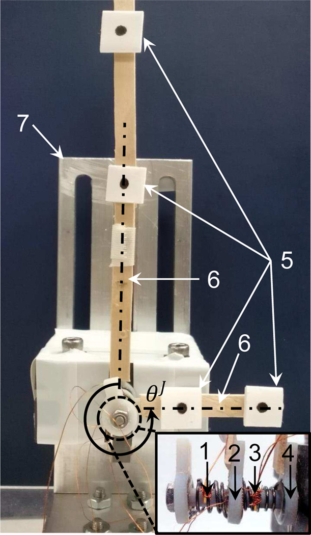
Fig. 8 shows the experimental setup. The shaft is fixed on the test stage and the output disk with support rods is removed. Two sticks with vision markers are pasted on the base and torsion disks, respectively. The vision camera (MicronTracker 2) tracks the markers by Lucas-Kanade optical flow method and all marker positions are calculated using OpenCV libraries to obtain the angle of the torsion actuator. A slave PC processes all vision-related computations and sends the angular value to a master PC. The two SMA torsion springs share the same current source (Maxon Motor Control ESCON 50/5) and each spring is connected to a transistor (International Rectifier IRL540N Mosfet) to select that spring to be heated under the control of the master PC via an I/O board (Sensory 626). The magnitude of heating current can be modulated by the master PC via voltage commands. The spring temperature is measured by micro thermistors (Alpha 56A1002-C3) and the measurement is sent to the master PC via the I/O board. We used thermally conductive epoxy (Loctite® 3888) to fix the thermistor on each SMA spring and ultra-thin copper wires to tightly tie the thermistor on the spring. Due to the small spring size, temperature variance is assumed to be negligible along the spring. The operating frequency of programs on the master PC is 67 Hz to coordinate the serial communication with the slave PC.
Fig. 8.
Experimental setup for the torsion actuator, including (1) SMA B, (2) torsion disk, (3) SMA A, (4) base disk, (5) vision markers, (6) wooden sticks, and (7) test stage [22], [23].
B. Controller Design
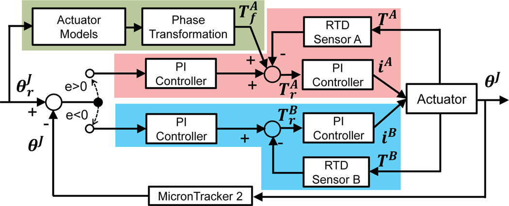
To control the SMA-based actuators, many linear and nonlinear controllers have been proposed to achieve precise tracking and disturbance rejection based on feedbacks such as temperature and strain change [28]–[30]. In our system, the measurable variables are the temperature of the springs and the angle of the actuator which is also the system output. Hence, we use a double-channel cascade PI controller (red and blue blocks) with feedforward compensation (green block) as shown in Fig. 9. The purpose of the double-channel controller is to promptly reduce tracking overshoot by actively heating the antagonistic SMA element [28]. For simplicity, the reference of the angular speed is assumed to be negative, so the feedforward compensation is applied on SMA A and SMA B is used to reduce overshoot. In the double-channel controller, a switching function determines which spring needs to be heated based on the output error given by , where eJ, , and θJ are the error, reference, and measurement of the actuator angle, respectively. When eJ < 0, SMA A is continuously heated and SMA B is not heated. When eJ > 0, the controller stops heating SMA A and starts heating SMA B to suppress its overshoot.
Fig. 9.
Block diagram of the double-channel cascade PI controller [22].
In the green block, the theoretical temperature is calculated as the feedforward compensation based on the reference of angular position and the quasi-static model. If the home positions of both springs are known, the reference of the angular position of SMA A can be obtained based on , and the references of and can be calculated from the quasi-static model. By substituting and into the phase transformation equations (4) and (5), the temperature reference for SMA A is obtained as the feedforward compensation. In each channel, the first PI controller computes the temperature reference as the feedback compensation and is given by: , where Tb is the temperature compensation based on the position feedback, and and are proportional and integral gains. The second PI controller computes the current reference to track the calculated temperature reference (Tr) and is given by: , where eT = Tr−T, T is the temperature measurement, ir is the current reference, and and are proportional and integral gains. All the controller gains were tuned by trial and error.
C. Experimental Results
To set a uniform home position for all tests, SMA A is heated to make the actuator rotate to the negative extremum and then naturally cooled to the room temperature. The resulting angular position is exclusively dependent on the spring properties and supposed to be constant for all tests, so it is regarded as the home position of the actuator. Our prior work on the characterization shows that the actuator has a motion range over 400° [23], which is sufficient for a torsion joint since most robotic joints need to rotate one cycle at most. In the full-range motion, the highest temperature of each spring is around 70°C and the temperature of the unheated spring increases slightly due to the heat transmission via ambient air [23]. Then, a series of evaluation tests were performed.
Sinusoidal Tracking
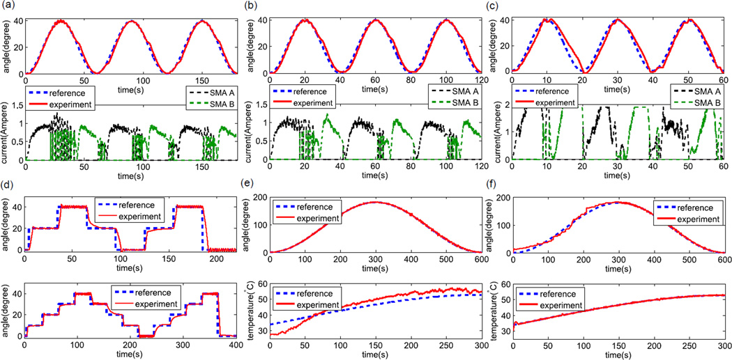
The results of three sinusoidal tracking tests are shown in Figs. 10(a), (b), and (c). Since the developed model assumes quasi-static motion, the feedforward compensation is not applied in these dynamic tests. When the tracking frequency is low (0.017 Hz and 0.025 Hz), the value of root mean square error (RMSE) is small and the performance is satisfactory. When the tracking frequency increases to 0.05 Hz, the performance deteriorates with phase shift, primarily due to the output saturation of the current source. In our system, the maximum output current is set to be 1.9A. Thus, it is predictable that higher tracking frequency can be achieved if a more powerful current source is used and electrical wires with better heat resistance are adopted. Active cooling using water is also under consideration, since it has been proven to be beneficial to improving the bandwidth of SMA actuators [31]. The two channels are frequently switched when the oscillation occurs around the position reference and the sign of the tracking error frequently changes, so alternate current spikes for SMA A and SMA B are observed.
Fig. 10.
Experimental results: (a) Sinusoidal tracking at 0.017 Hz frequency (RMSE value is 1.67°), (b) Sinusoidal tracking at 0.025 Hz frequency (RMSE value is 2.05°), (c) Sinusoidal tracking at 0.050 Hz frequency (RMSE value is 3.60°), (d) step input response with the time step of 30s and step size of 20° (upper) and time step of 30s and step size of 10° (lower), (e) Quasi-static tracking with both feedforward and feedback compensation from 0s to 300s (RMSE value is 1.86°) and only feedback compensation from 300s to 600s (RMSE value is 2.24°), and (f) Quasi-static tracking with only feedforward compensation applied from 0s to 300s (RMSE value is 8.19°) and only feedback compensation applied from 300s to 600s (RMSE value is 2.58°) [22].
Step Input Response
The results of step input response tests are shown in Fig. 10(d). Since SMA B is heated when SMA A is at low temperature during the first several steps (0s to 65s in the upper case and 0s to 125s in the lower case), the antagonistic torque applied by SMA A is relatively small, so the response is fast with the rise time about 4s for the upper case and 2s for the lower case. The rise time for the remaining steps increases with the longest rise time around 20s, because the antagonistic SMA torsion spring which is heated before the actuator reverses still has high temperature and large stiffness. Considering that most surgical procedures do not require high-speed motion, the actuator can meet the application requirements, as the steady state error of each step diminishes to zero within finite time. Slight oscillation about ±1.5° occurs when the reference angle is 0° and 40°, probably because of the nonlinear dynamics of SMA. When the actuator works in an environment with sufficient damping, the oscillation can be probably suppressed. The feedforward compensation is also not applied in these tests.
Quasi-Static Tracking
The proposed controller is evaluated by two quasi-static tracking tests, in which the designed reference is a sinusoidal cycle and its period is as long as 600s to make the motion quasi-static. In the first test, both the feedforward and feedback compensations are applied in the first half cycle and only the feedback compensation is applied in the second half cycle. Fig. 10(e) shows little difference in the tracking error between these two halves and indicates that the model-based feedforward compensation cannot improve the tracking performance significantly. However, the feedforward compensation shows its utility when the system feedback is unavailable. Since it is challenging to incorporate miniature encoders, vision feedback is usually used. But since the vision system is not robust, it is very likely that visual features are lost due to occlusion. So in the second test, we apply only the feedforward compensation in the first half cycle, which simulates a failure of the vision system, and only the feedback compensation in the second half cycle, which simulates a recovery of the vision system. The experimental results in Fig. 10(f) show that the RMSE value is about 8.19° in the first half cycle, probably caused by the unmodeled factors, such as the temperature change in the antagonistic spring and the nonuniformity of spring turns. Although the tracking error is larger than that in the second half cycle, we can effectively avoid unpredictable rotation when the vision system fails. When only the feedforward compensation is applied, the actuator works in the open-loop status and the relatively small tracking error also validates the derived quasi-static model. In both cases, the feedforward compensation is only applied in the first half cycle, because the system model assumes that the antagonistic spring is at the room temperature, which is invalid in the second half cycle as the antagonistic spring has already been heated in the first half cycle.
V. Robot Demonstration
To demonstrate its working performance, the developed actuator is integrated with a surgical robot prototype as shown in Fig. 1. Considering that the robot needs to work in the humid environment, it is necessary to protect the SMA elements and electrical wires to ensure effective Joule heating and to avoid short circuit. To seal the torsion actuator, an improved design has been developed as shown in Fig. 11. The bolt is replaced by a cylindrical shell, within which the torsion disk can rotate. The base and top disks are replaced by the bottom and top covers. The SMA torsion springs are installed within the shell by fixing its ends on the torsion disk and the covers. A shaft with a through hole is coaxially integrated with the torsion disk. Therefore, by applying Joule heating alternately, the torsion disk can bi-directionally rotate together with the shaft. The bottom surface of the shaft and the micro steps on the shaft close to the top cover can constrain the axial motion of the torsion disk. The electrical wires connected to the springs pass through the micro holes on the shaft and go through the hole to the base link of the robot, so all components of the torsion actuator are insulated within the shell. To reduce the friction torque, the torsion disk with the shaft is made of brass by using 3D printing techniques (Shapeways, Inc.) and grease is filled between the torsion disk and the shell.
Fig. 11.
Mechanical design of the improved torsion actuator: (a) Assembly view and (b) Exploded view [22].
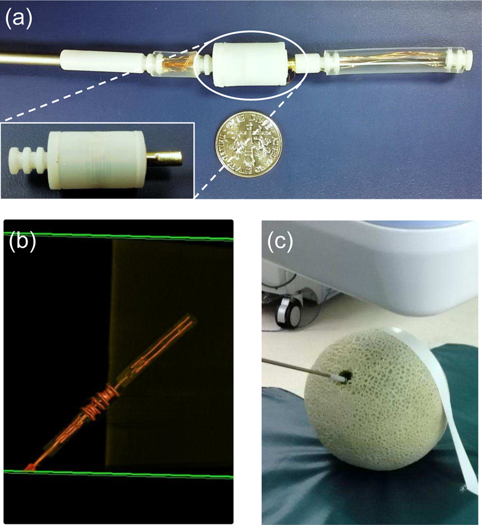
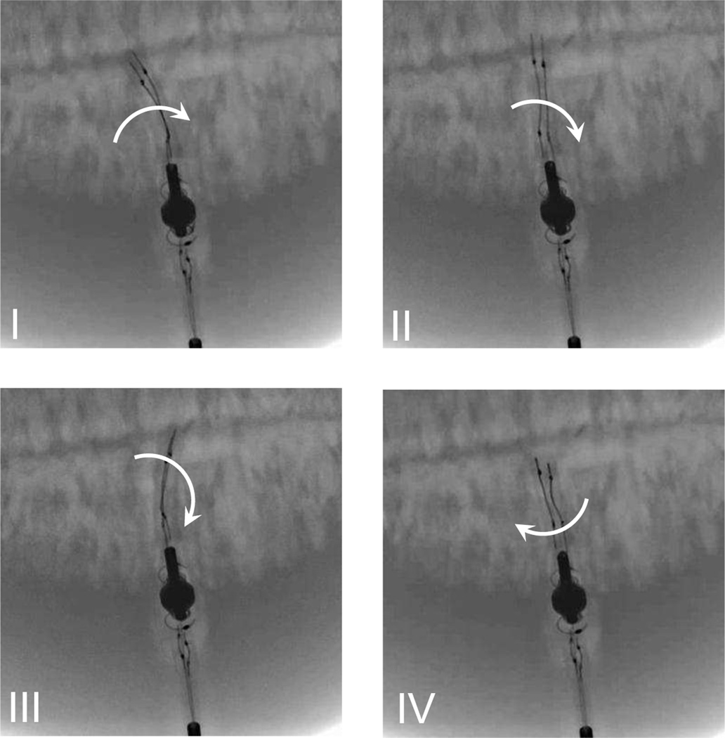
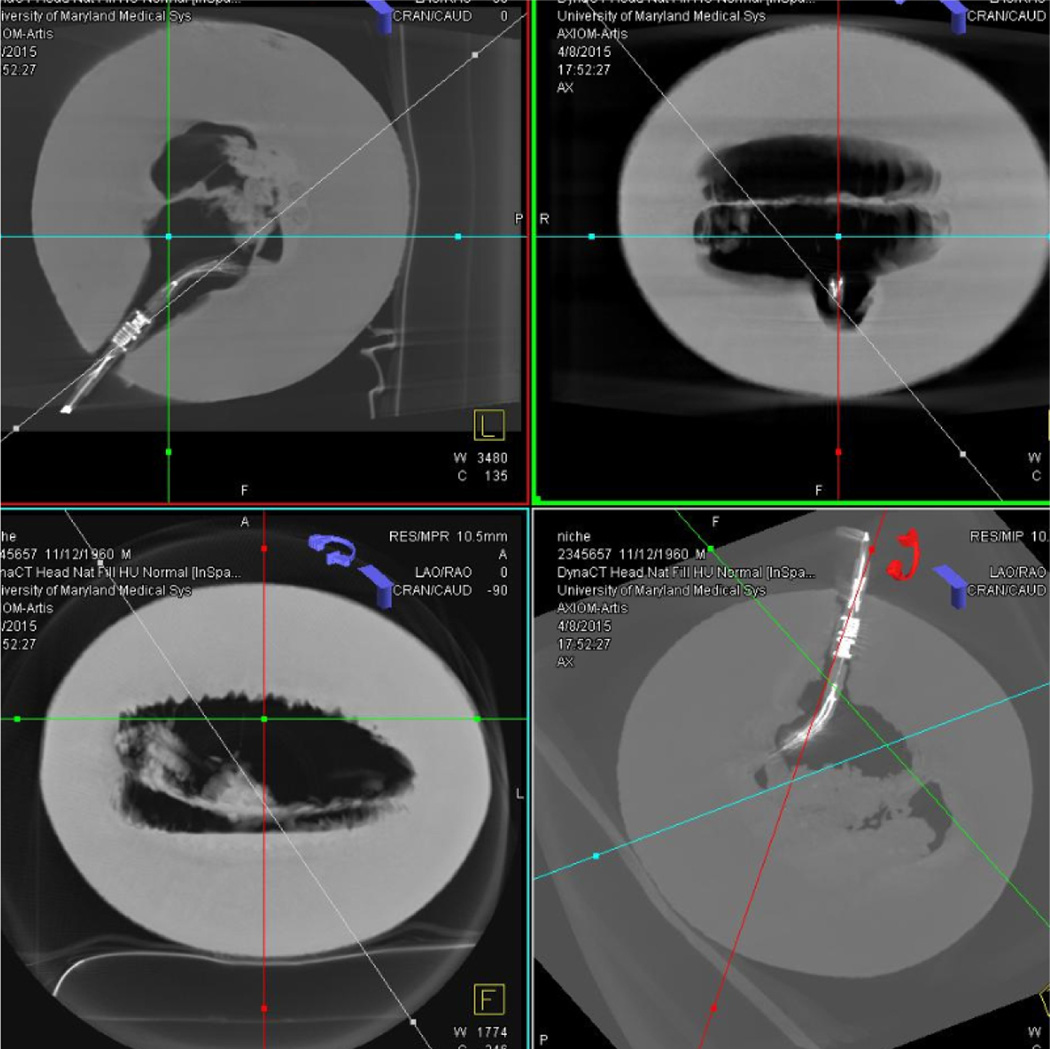
Fig. 12(a) shows the robot prototype with the improved torsion actuator, where the base link is fixed on the tip of an aluminum rod. Fig. 12(b) shows the shaded surface display of the robot prototype using a C-Arm CT scanner. It demonstrates the ease of identifying the robot along with its individual components, such as the torsion joint and the distal bending tip, by using Dyna CT image reconstructions. The robot is manually inserted into a cantaloupe (at its core), which mimics a tissue phantom, to evaluate its working performance in the humid environment as shown in Fig. 12(c). Under C-Arm CT image guidance, a constant current of 1.9A is provided to heat the SMA torsion springs and actuate the torsion joint. Fig. 13 shows the rotary motion of the torsion joint for about 300° (by visual estimation) in 30s with the bent tip. This actual motion range is smaller than the measurement in air, probably because: 1) The friction torque is applied on the torsion disk and the shaft by the shell; 2) The soft tissue within the cantaloupe applies resistant force on the torsion disk when the tissue is pressed by the moving tip. These two factors not only reduce the motion range, but also increase the temperature required to complete the SMA phase transformation. The highest heating temperature is limited by the maximum heating current and the heat resistance of the robot components. Fig. 14 shows the multi-planar display capabilities of Dyna CT and I-Guide reconstructions during the robot manipulation within the cantaloupe. This allows the operator to assess the individual components of the robot in relationship to adjacent soft-tissue structures in a variety of user defined planes.
Fig. 12.
Experimental setup for the robot demonstration: (a) Improved robot prototype, (b) Shaded surface display of the robot using a C-Arm CT scanner, and (c) Testing the robot prototype within a cantaloupe under C-Arm CT image guidance.
Fig. 13.
Demonstration of the torsion joint motion with the distal bending tip within a cantaloupe.
Fig. 14.
Screenshots of the multi-planar display capabilities of Dyna CT and I-Guide reconstructions during the robot manipulation within a cantaloupe.
VI. Discussion and Conclusions
In this paper, we have proposed an innovative torsion actuator based on SMA torsion springs with a dimension much smaller than other related works. Systematic analysis was performed to model the torsion actuator and search the optimal pre-deformation for the maximum motion range. Then, we conducted several experiments to evaluate the working performance of the actuator and verify the derived model. To demonstrate the developed actuator, it was integrated into a meso-scale surgical robot and actuated in the humid environment under C-Arm CT image guidance. The motion range of the torsion actuator is smaller in soft tissue than in air, but it can be possibly addressed by: 1) Using micro bearings to reduce the friction torque applied on the shaft; 2) Using a more powerful power supply and electric wires with better heat resistance to generate higher heating temperature; 3) Using nitinol wires with a larger diameter to make SMA torsion springs that generate larger recovery force. The stall torque of this actuator under different block angles was measured with varying temperature. Although its maximum stall torque (about 10 mNm) is smaller than that presented in the related work (hundreds of mNm) [15], the torque capability of our developed actuator is still comparable considering its much smaller size. Since the hemorrhage within the brain tissue is soft, the torque output of the developed actuator is believed to be sufficient for the neurosurgical application, while future in vivo and ex vivo studies are required. Based on the experimental results of sinusoidal tracking, the positioning accuracy of the controlled system can reach about 1 mm for a 30 mm radius rotation to cover a simulated spherical hemorrhage described in [20], which is comparable to the reported accuracy for the commercial Navigus system [32]. To improve the safety of the torsion actuator, biocompatible materials need to be used in the fabrication and the size of the torsion actuator needs to be further miniaturized. In the future, we plan to improve the system design to achieve sufficient motion range in the soft tissue and develop a dynamic controller to enhance the tracking performance. A feedback interface based on the CT imaging module needs to be developed to quantitatively evaluate the robot in real time.
Contributor Information
Jun Sheng, Medical Robotics and Automation Laboratory (RoboMed) in the Wallace H. Coulter Department of Biomedical Engineering, Georgia Institute of Technology, Atlanta, GA 30332 USA.
Dheeraj Gandhi, University of Maryland School of Medicine, Baltimore, MD 21201 USA.
Rao Gullapalli, University of Maryland School of Medicine, Baltimore, MD 21201 USA.
J. Marc Simard, University of Maryland School of Medicine, Baltimore, MD 21201 USA.
Jaydev P. Desai, Medical Robotics and Automation Laboratory (RoboMed) in the Wallace H. Coulter Department of Biomedical Engineering, Georgia Institute of Technology, Atlanta, GA 30332 USA.
References
- 1.Jamisola RS, Maciejewski AA, Roberts RG. Proceedings 2004 IEEE International Conference on Robotics and Automation. Vol. 5. IEEE; 2004. Failure-tolerant path planning for the PA-10 robot operating amongst obstacles; pp. 4995–5000. [Google Scholar]
- 2.Kennedy CW, Desai JP. Modeling and control of the Mitsubishi PA-10 robot arm harmonic drive system. Mechatronics, IEEE/ASME Transactions on. 2005;10(3):263–274. [Google Scholar]
- 3.Lakshmanan K, Sachdev A, Xie Z, Berenson D, Goldberg K, Abbeel P. Experimental Robotics. Springer; 2013. A constraint-aware motion planning algorithm for robotic folding of clothes; pp. 547–562. [Google Scholar]
- 4.Hess J, Tipaldi GD, Burgard W. Intelligent Robots and Systems (IROS), 2012 IEEE/RSJ International Conference on. IEEE; 2012. Null space optimization for effective coverage of 3D surfaces using redundant manipulators; pp. 1923–1928. [Google Scholar]
- 5.Flacco F, De Luca A, Khatib O. Robotics and Automation (ICRA), 2012 IEEE International Conference on. IEEE; 2012. Motion control of redundant robots under joint constraints: Saturation in the null space; pp. 285–292. [Google Scholar]
- 6.Bischoff R, Kurth ea. The KUKA-DLR Lightweight Robot arma new reference platform for robotics research and manufacturing; Robotics (ISR), Proceedings 2010 41st international symposium on and 2010 6th German Conference on robotics (ROBOTIK); 2010. pp. 1–8. [Google Scholar]
- 7.Toshiyoshi H, Fujita H. Electrostatic micro torsion mirrors for an optical switch matrix. Microelectromechanical Systems, Journal of. 1996;5(4):231–237. [Google Scholar]
- 8.Ayvali E, Liang C-P, Ho M, Chen Y, Desai JP. Towards a discretely actuated steerable cannula for diagnostic and therapeutic procedures. The International Journal of Robotics Research. 2012;31(5):588–603. doi: 10.1177/0278364912442429. [DOI] [PMC free article] [PubMed] [Google Scholar]
- 9.Ho M, McMillan AB, Simard JM, Gullapalli R, Desai JP. Towards a meso-scale SMA-actuated MRI-compatible neurosurgical robot. IEEE Transaction on Robotics. 2012;28(1):213–222. doi: 10.1109/TRO.2011.2165371. [DOI] [PMC free article] [PubMed] [Google Scholar]
- 10.Ho M, Desai JP. Modeling, characterization and control of antagonistic SMA springs for use in a neurosurgical robot; IEEE International Conference on Robotics and Automation; 2013. pp. 2503–2508. [Google Scholar]
- 11.Hsieh J, Fang W. A novel microelectrostatic torsional actuator. Sensors and Actuators A: Physical. 2000;79(1):64–70. [Google Scholar]
- 12.Kanda T, Makino A, Ono T, Suzumori K, Morita T, Kurosawa MK. A micro ultrasonic motor using a micro-machined cylindrical bulk pzt transducer. Sensors and Actuators A: physical. 2006;127(1):131–138. [Google Scholar]
- 13.Qi Z, Liang PC, Ting MY, Rang KF, Hua FZ. Piezoelectric rotary motor based on active bulk torsional element with grooved helical electrodes. Mechatronics, IEEE/ASME Transactions on. 2012;17(2):260–268. [Google Scholar]
- 14.Ayvali E, Desai JP. Robotics and Automation (ICRA), 2014 IEEE International Conference on. IEEE; 2014. Accurate in-plane and out-of-plane ultrasound-based tracking of the discretely actuated steerable cannula; pp. 5896–5901. [Google Scholar]
- 15.Huang W. Ph.D. Thesis. University of Cambridge: Department of Engineering; 1998. Shape memory alloys and their application to actuators for deployable structures. [Google Scholar]
- 16.Song G. Design and control of a Nitinol wire actuated rotary servo. Smart materials and Structures. 2007;16(5):1796. [Google Scholar]
- 17.Lan C-C, Wang J-H, Fan C-H. Optimal design of rotary manipulators using shape memory alloy wire actuated flexures. Sensors and Actuators A: Physical. 2009;153(2):258–266. [Google Scholar]
- 18.Nishihara T, Morita A, Teraoka A, Kirino T. Endoscopy-guided removal of spontaneous intracerebral hemorrhage: comparison with computer tomography-guided stereotactic evacuation. Child’s Nervous System. 2007;23(6):677–683. doi: 10.1007/s00381-007-0325-6. [DOI] [PubMed] [Google Scholar]
- 19.Miller CM, Vespa P, Saver JL, Kidwell CS, Carmichael ST, Alger J, Frazee J, Starkman S, Liebeskind D, Nenov V, et al. Image-guided endoscopic evacuation of spontaneous intracerebral hemorrhage. Surgical neurology. 2008;69(5):441–446. doi: 10.1016/j.surneu.2007.12.016. [DOI] [PMC free article] [PubMed] [Google Scholar]
- 20.Burgner J, Swaney PJ, Lathrop RA, Weaver KD, Webster RJ. Debulking from within: a robotic steerable cannula for intracerebral hemorrhage evacuation. Biomedical Engineering, IEEE Transactions on. 2013;60(9):2567–2575. doi: 10.1109/TBME.2013.2260860. [DOI] [PubMed] [Google Scholar]
- 21.Sheng J, Desai JP. Intelligent Robots and Systems (IROS), 2015 IEEE/RSJ International Conference on. IEEE; 2015. Towards a SMA-actuated neurosurgical intracerebral hemorrhage evacuation (NICHE) robot; pp. 3805–3810. [Google Scholar]
- 22.Sheng J, Desai JP. Intelligent Robots and Systems (IROS), 2015 IEEE/RSJ International Conference on. IEEE; 2015. A novel meso-scale SMA-actuated torsion actuator; pp. 4718–4723. [Google Scholar]
- 23.Sheng J, Desai JP. Design, modeling and characterization of a novel meso-scale SMA-actuated torsion actuator. Smart Materials and Structures. 2015;24(10):105005. doi: 10.1088/0964-1726/24/10/105005. [DOI] [PMC free article] [PubMed] [Google Scholar]
- 24.Liang C, Rogers C. One-dimensional thermomechanical constitutive relations for shape memory materials. Journal of intelligent material systems and structures. 1990;1(2):207–234. [Google Scholar]
- 25.Ayvali E, Desai JP. Robotics and Automation (ICRA), 2012 IEEE International Conference on. IEEE; 2012. Towards a discretely actuated steerable cannula; pp. 1614–1619. [DOI] [PMC free article] [PubMed] [Google Scholar]
- 26.De Sars V, Haliyo S, Szewczyk J. A practical approach to the design and control of active endoscopes. Mechatronics. 2010;20(2):251–264. [Google Scholar]
- 27.Shaw JA, Churchill CB, Iadicola M. Tips and tricks for characterizing shape memory alloy wire: part 1-differential scanning calorimetry and basic phenomena. Experimental Techniques. 2008;32(5):55–62. [Google Scholar]
- 28.Guo Z, Yu H, Wee L-B. Intelligent Robots and Systems (IROS), 2013 IEEE/RSJ International Conference on. IEEE; 2013. Design of a novel compliant differential shape memory alloy actuator; pp. 4925–4930. [Google Scholar]
- 29.Moallem M, Tabrizi V. Tracking control of an antagonistic shape memory alloy actuator pair. Control Systems Technology, IEEE Transactions on. 2009;17(1):184–190. [Google Scholar]
- 30.Jayender J, Patel RV, Nikumb S, Ostojic M. Modeling and control of shape memory alloy actuators. Control Systems Technology, IEEE Transactions on. 2008;16(2):279–287. [Google Scholar]
- 31.Cheng SS, Desai JP. 2015 IEEE International Conference on Robotics and Automation (ICRA) IEEE; 2015. Towards high frequency actuation of SMA spring for the neurosurgical robot-MINIR-II; pp. 2580–2585. [Google Scholar]
- 32.Quiñones-Hinojosa A, Ware ML, Sanai N, McDermott MW. Assessment of image guided accuracy in a skull model: comparison of frameless stereotaxy techniques vs. frame-based localization. Journal of neuro-oncology. 2006;76(1):65–70. doi: 10.1007/s11060-005-2915-z. [DOI] [PubMed] [Google Scholar]


