Significance
Protein nanofibrils formed by self-assembly have emerged as a promising foundation for the design of bio-based materials with enhanced mechanical properties or new functionality. To make use of the extraordinary properties of these structures in materials design, improved understanding of the assembly of the nanofibrils into macroscale materials is crucial. Here we demonstrate that micrometer-sized protein fibers can be created from protein nanofibrils using a simple microfluidics setup. The assembly mechanism of these fibers is elucidated using high-resolution small-angle X-ray studies in combination with rheology measurements of the corresponding hydrogels. The results reveal essential parameters associated with the fiber formation and provide insights about the assembly processes of hierarchical protein materials.
Keywords: protein nanofibrils, amyloid, hierarchical assembly, flow focusing, small-angle X-ray scattering
Abstract
Some of the most remarkable materials in nature are made from proteins. The properties of these materials are closely connected to the hierarchical assembly of the protein building blocks. In this perspective, amyloid-like protein nanofibrils (PNFs) have emerged as a promising foundation for the synthesis of novel bio-based materials for a variety of applications. Whereas recent advances have revealed the molecular structure of PNFs, the mechanisms associated with fibril–fibril interactions and their assembly into macroscale structures remain largely unexplored. Here, we show that whey PNFs can be assembled into microfibers using a flow-focusing approach and without the addition of plasticizers or cross-linkers. Microfocus small-angle X-ray scattering allows us to monitor the fibril orientation in the microchannel and compare the assembly processes of PNFs of distinct morphologies. We find that the strongest fiber is obtained with a sufficient balance between ordered nanostructure and fibril entanglement. The results provide insights in the behavior of protein nanostructures under laminar flow conditions and their assembly mechanism into hierarchical macroscopic structures.
Proteins are widely used in nature to create high-performance materials that can have both extraordinary mechanical properties (similar to muscles, silks) and sophisticated functionalities (e.g., adhesion, biological signaling) (1). The characteristics of these materials are intimately connected to the hierarchical assembly of the protein building blocks with well-defined organization at all structural levels (2). Improved knowledge about how to control the assembly of protein molecules into higher-order structures would open the possibilities to create novel bio-based materials for a variety of applications. In this perspective, the ability of protein molecules to undergo nonnative self-assembly into protein nanofibrils (PNFs) with highly organized supramolecular structures is of significant interest (3). The formation of PNFs was initially observed in association with diseases, such as Alzheimer’s and Parkinson’s diseases, and type II diabetes, where human organs are impaired by fibrous protein inclusions referred to as amyloid (4). However, several non–disease-related proteins have also been shown to form amyloid-like fibrils, e.g., the bovine whey protein β-lactoglobulin (5), hen-egg lysozyme (6), and soybean proteins (7). The unique fibrous structures of PNFs have the potential for being the building block of protein-based nanomaterials and to be used as scaffolds for applications such as tissue engineering, drug delivery systems, and biosensors (3). PNFs are characterized by intermolecular β-sheet structures, where the peptide backbones are oriented perpendicularly to the fibril axis and connected through a network of hydrogen bonds (4, 8). This provides them with stiffness equivalent to silk and strength comparable to steel (2, 8). Moreover, the PNFs are often found to be polymorphic with respect to their molecular structure, length distribution, and degree of curvature, depending on the starting material and the conditions for fibril synthesis (2, 4, 9, 10), which might open for design of material properties by the use of different nanoscale building blocks.
In bottom-up assembly of materials based on PNFs, it is crucial to gain control over the microscale structures formed by them. The phase behavior of PNFs in relation to physiochemical parameters (e.g., pH, protein concentration, and ionic strength) has been studied in bulk solution (11), providing some understanding of their microscale assembly mechanisms. However, forced extension toward alignment of fibrils is a common component of wet spinning techniques, which have emerged as promising procedures for controlled fiber formation (12–18). We here make use of recent insights into the behavior of nanofibrils under elongational flow and the developments in X-ray transparent small-scale flow devices and high-brilliance microfocused X-ray beams (13, 17, 19) to carry out in situ investigations of the assembly of PNFs during the flow orientation.
Results and Discussion
Preparation and Characterization of Whey PNFs.
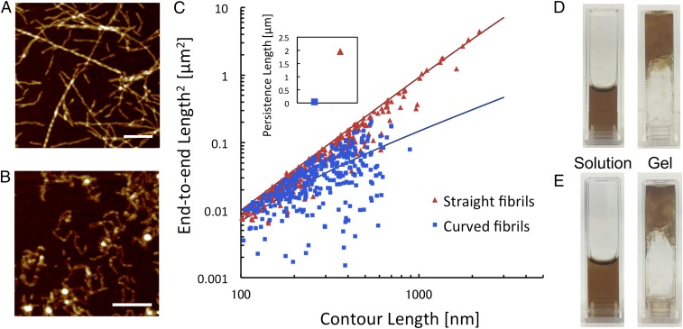
The whey protein β-lactoglobulin forms amyloid-like fibrils under several different conditions, including high concentrations of urea (20), in the presence of alcohols (21), and at low pH and elevated temperature (5, 22). At low pH and high temperature, the fibrillation proceeds through hydrolysis of the protein into smaller peptide fragments and some of these peptides spontaneously assemble into PNFs (23). In the current study, we used whey protein isolate (WPI) as starting material because it gives us access to large amounts of PNFs and is a potential raw material for industrial-scale production of protein-based materials. PNFs formed from WPI when incubated at pH 2, 90 °C, and low ionic strength for 1–3 d (Fig. 1 A and B). Although WPI is a mixture of different proteins, previous studies have shown that PNFs formed under the applied conditions are built from β-lactoglobulin–derived peptides (24). Interestingly, vandenAkker et al. demonstrated that pure β-lactoglobulin can assemble into fibrils with different morphology depending on the initial protein concentration (10). In their study, low protein concentration (3%) resulted in long and straight fibrils whereas short, worm-like structures were formed at higher concentrations (7.5%). We find that a similar morphological switch exists for PNFs formed from WPI solution. At lower WPI concentrations (<4%), we obtain straight and long (up to several micrometers) PNFs (Fig. 1A), whereas at higher concentrations (>6%) the fibrils are short, more aggregated, and have a higher degree of curvature (Fig. 1B). A brief quantification of the morphological differences in terms of persistence lengths showed that the average value of the straight fibrils is ∼1,960 nm, which is almost 50× higher than for the curved fibrils (41 nm) (Fig. 1C). Moreover, the straight fibrils have an apparent height of 4.1 ± 1.1 nm whereas the curved fibrils are thinner (2.5 ± 0.5 nm). Assuming that the straight fibrils are built from 2–3 protofilaments, as described by others (10, 25), and that these filaments have the same cross-sectional area as the curved fibrils, we can get an estimate of the relative elastic moduli of the two classes of PNFs. The straight fibrils then appear to have an elastic modulus that is 15–25× higher than the curved fibrils. Values for PNFs similar to the straight fibrils have previously been reported to be ∼5 GPa (26), which means that the curved PNFs would have an elastic modulus between 0.2 and 0.4 GPa.
Fig. 1.
Two distinct morphological classes of PNFs formed from WPI. (A and B) AFM images of straight (A) and curved (B) fibrils prepared from initial WPI concentrations of 4% and 8%, respectively. [Scale bars: 1 μm (A) and 0.3 μm (B).] (C) Plot of the squared end-to-end distance versus contour length for straight and curved PNFs with the best-fit curves used to calculate the persistence lengths. (Inset) Final values of persistence lengths for straight and curved fibrils. (D and E) Photographs of PNF dispersions, before (Left) and after (Right) the addition of acetate buffer (pH 5.2) for straight fibrils (D) and curved fibrils (E).
The PNF solutions were extensively dialyzed to remove nonfibrillated proteins and peptides. The dialyzed dispersions of straight, as well as curved, PNFs undergo a phase transition to a gel (arrested state) when the pH is increased to 5.2 (Fig. 1 D and E), which is close to the isoelectric point of β-lactoglobulin (11). Importantly, the corresponding changes in pH for nondialyzed samples resulted in macroscopic phase separation with opaque aggregates rather than a gel, signifying that nonfibrillated proteins could impede the gel network formation.
Flow-Induced Formation of PNF Microfibers.
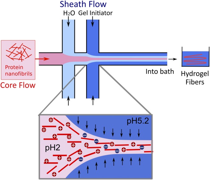
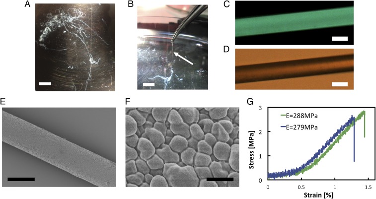
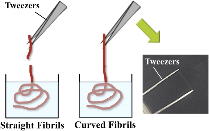
The pH-induced gel transition of the PNF dispersions was explored in combination with flow-induced alignment to assemble fibrils into microfibers. We used a double-focusing millimeter-scaled device (Fig. 2 and Fig. S1) with a core flow of PNF dispersion and two focusing steps of the sheath flows (27). The laminar flow conditions along the channel enable precise control of pH, which is required for the transition into a gel state for the PNF dispersions. At the first focusing step, deionized water was used to enable the alignment of fibrils in the presence of an elongational flow field, whereas the flow at the second step contained acetate buffer at pH 5.2, which in turn locked the aligned structure of PNFs. We first examined the assembly of straight fibrils, where the concentration of PNF in the core flow varied from 0.45% to 1.8% (the concentrations are lower than the above-mentioned initial concentrations as they refer to the pure PNF content of the dialyzed dispersions). Surprisingly, no conditions were found where fibrils could be assembled into fibers that were strong enough to be picked out from the bath solution. Weak hydrogel fibers were obtained that were unable to withstand the surface tension at the liquid–air interface when pulled out. The curved fibrils, on the other hand, were able to produce hydrogel fibers that were strong enough to overcome the surface tension (Fig. 3 A and B and Fig. S2). Notably, the fiber formation with curved fibrils was possible at a concentration of 1.8%, where straight fibrils were not able to produce strong enough hydrogel fibers. Importantly, nonfibrillar solutions of WPI could not produce fiber-like structures at any concentration, highlighting the importance of ordered nanostructures in the starting material.
Fig. 2.
Schematic of the double flow-focusing device used for fiber assembly. All channels have a cross-section of 1 × 1 mm2. The PNF dispersion is injected in the core flow. Deionized water injected in the first sheath causes alignment of PNFs and prevents shear from the channel wall. Acetate buffer (pH 5.2) in the second sheath further increases the alignment and initiates the transition to a hydrogel through a change in pH, as illustrated in the zoomed view (Bottom). The channel ends in a bath containing acetate buffer (pH 5.2).
Fig. S1.
Detailed illustration of the flow-focusing device used to assemble PNFs into microfibers. (A) The flow setup consists of syringe pumps, a flow-focusing channel, and a bath for the outlet of protein hydrogel fibers. Syringe pumps were used to control the flow rates of the core and sheath flows. The outlet of the channel was submerged into the bath solution. (B) The flow channel was milled in a 1-mm-thick stainless steel plate and sandwiched between two Plexiglas plates. Over the Plexiglas plates, two aluminum plates were placed on either side and screwed together to prevent leakage. All of the channels in the flow-focusing geometry were 1 mm in width.
Fig. 3.
Characterization of microfibers obtained from curved PNFs. (A) Photograph of a hydrogel fiber in the bath solution after spinning in the flow-focusing setup. (B) The fibers made from curved PNFs can be picked up from the bath. (C) Fluorescence microscope image of a fiber stained with thioflavin T. (D) Optical microscope image of the fiber shown in C. (E) SEM image of a dried fiber. (F) Zoomed SEM view of the fiber surface. (G) Representative stress–strain curves of dried fibers. [Scale bars: 1 cm (A and B), 30 μm (C–E), and 1 μm (F).]
Fig. S2.
Schematic of the extraction of hydrogel fibers out of the bath solution. Unlike the hydrogel fibers from straight PNFs (Left) the fibers from curved PNFs (Middle) were strong enough to lift them out of the bath and dry as shown (Right).
The extracted hydrogel fibers were dried in air (Fig. S3) and investigated with scanning electron microscopy (SEM). The images reveal a smooth surface with constant cross-section along the diameter (Fig. 3E). From the close-up view of the fiber surface (Fig. 3F), it can be seen that the PNFs are assembled into closely packed graupel-like units of the dimensions of a few hundred nanometers. Interestingly, this surface morphology is similar to previous observations of the assembly of recombinant spider silk proteins, where colloidal aggregates clustered together to form higher-order structures (16). It is, however, different from mechanically more rigid particles like cellulose nanofibrils, where rod-like linearly arranged units were observed on the fiber surface (13). The presence of amyloid-like structure in the fibers was confirmed by fluorescence microscopy (Fig. 3 C and D), where a homogeneous binding of the amyloidophilic dye thioflavin T over the fiber surface was observed. This indicates that the fibers can be functionalized with fluorophores as shown in other PNF materials (28). We also characterized the mechanical properties of the fibers. Stress–strain curves reveal a rather brittle material with modulus up to 288 MPa and strain at break of ∼1.5%, as shown in Fig. 3G. Hence, the stiffness of fibers is in the same range as expected for individual PNFs (2), whereas the ultimate tensile strength is significantly lower. Interestingly, the measured elastic modulus is in good agreement with the estimated values for curved fibrils (vide supra).
Fig. S3.
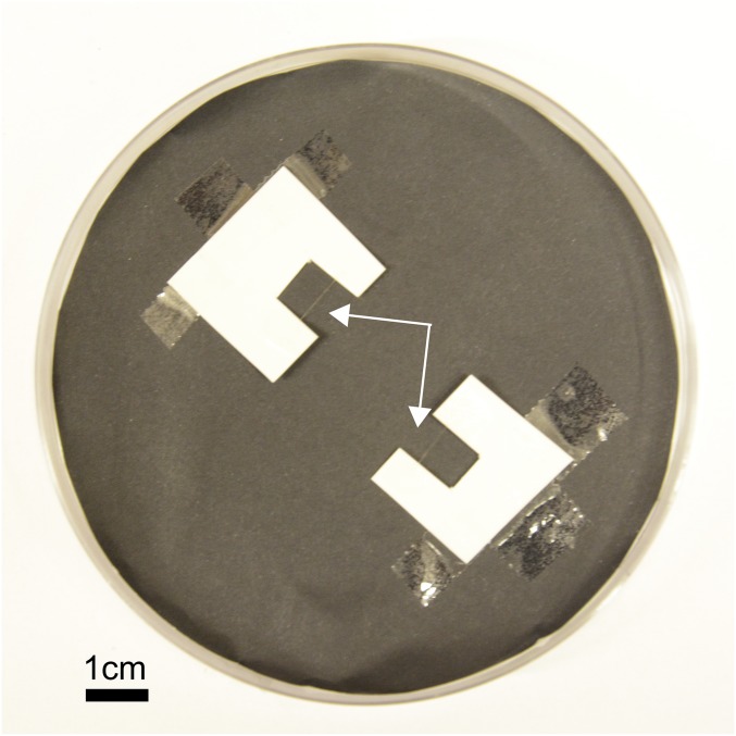
Drying of fibers for mechanical testing and SEM. (Scale bar: 1 cm.)
In Situ Investigations of PNF Alignment.
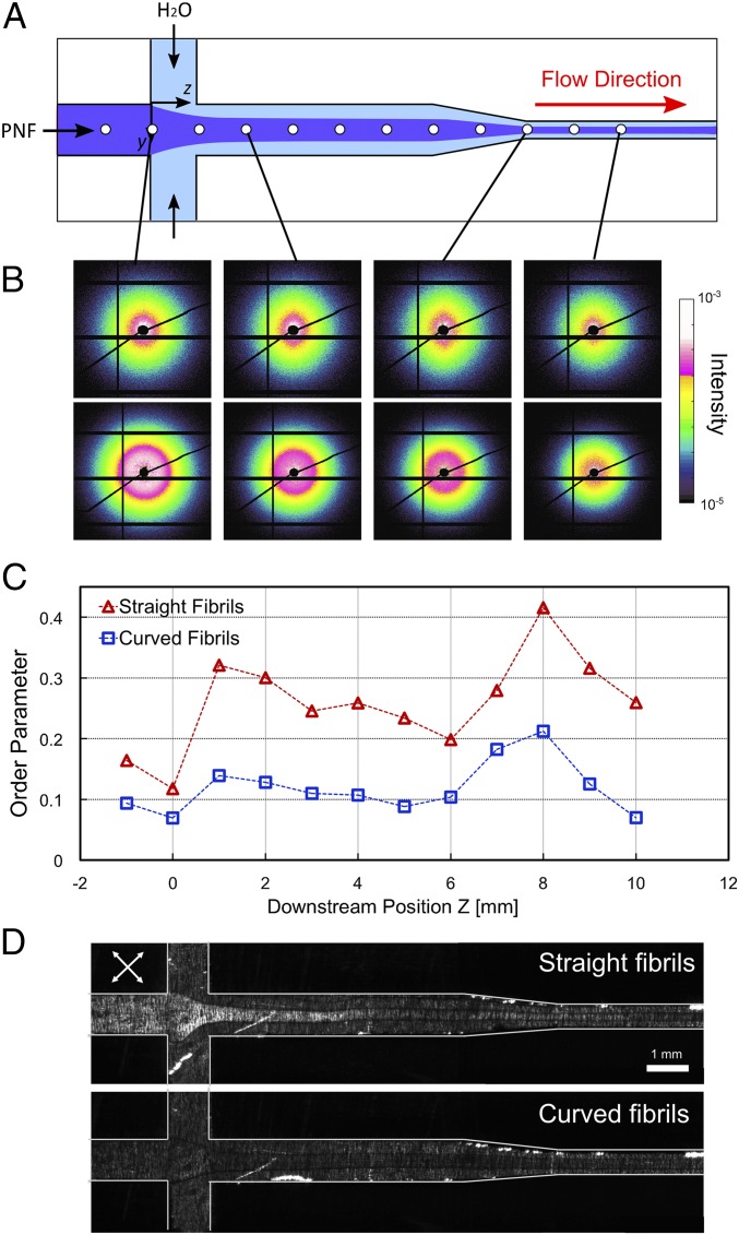
To understand the behavior of straight and curved PNFs in the flow-focusing channel, we carried out synchrotron microfocus small-angle X-ray scattering (μSAXS) experiments (29). A channel with slightly modified geometry was used for these experiments. In this channel the second focusing step was replaced by a contraction (Fig. 4A), because the gel transition was not required for this study. However, both channel geometries function by the same principle of elongational flow. The behavior of PNFs was studied in terms of alignment defined by the order parameter calculated from the obtained μSAXS images (Methods for detail). An order parameter of 1 represents fully aligned fibrils in the streamwise direction, whereas 0 represents an isotropic distribution (random orientation). The variation of the order parameters along the channel indicated increased alignment of fibrils immediately after the focusing and the contraction steps (Fig. 4 B and C). Subsequently, the order parameters decreased again, indicating relaxation of the aligned fibrils toward isotropy, which is primarily due to Brownian motion. Substantial differences between the behaviors of straight and curved PNFs were observed: The curved fibrils were poorly oriented in the flow direction, as indicated by the lower values of order parameter (Fig. 4C). The maximum order parameter reached by the straight fibrils was 0.41, which is almost twice the highest value for the curved fibrils (0.21). The μSAXS results are in agreement with observations by polarized optical microscopy (Fig. 4D) in which the straight fibrils displayed birefringence at the location where we observed increased order parameter in the μSAXS measurements. However, no birefringence was observed for the curved fibrils, which confirms a lower degree of alignment.
Fig. 4.
Alignment of PNFs in the microchannel. (A) Schematic of the channel geometry used for the SAXS experiments. White circles show the locations where in situ measurements were carried out. The experiments were performed at the center of the channel at different downstream positions. (B) μSAXS patterns at selected locations in the channel for straight (Upper Row) and curved (Lower Row) fibrils. (C) Local order parameters calculated from SAXS patterns as a function of downstream position z in the channel. The locations marked with circles in A correspond to the data points shown in C. (D) Images of the channel placed between two crossed polarization filters rotated 45° from the vertical axis (white arrows). For straight fibrils, birefringence due to the alignment is observed after the focusing step. In contrast, no birefringence is detected for the curved fibrils.
Micro- and Molecular Structure of PNFs in the Gel State.
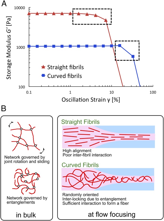
To assess the interfibrillar interactions for the two morphological classes of PNFs, we investigated the fracture behavior of the gel networks under macroscopic strains using rheometry (Fig. S4). At similar concentrations of straight and curved fibrils, a large difference in the value of initial storage modulus (G′) was observed (Fig. 5A). The higher modulus for the straight fibrils might be associated with an initial alignment of fibrils in a nematic phase (30). The results also reveal a difference in response to the increasing oscillatory strains before gel fracture. Gels from the straight fibrils undergo a gradual fracture as indicated by the slow decrease of storage modulus, whereas for the curved fibrils, a sudden drop of the modulus close to the fracture point is detected (Fig. 5A). The slow deformation for gels formed by straight fibrils is presumably associated with rotation and sliding of the fibrils, which plastically deforms their network. On the other hand, the gel of curved fibrils fractured without plastic deformation, indicating that fibrils might be interlocked to a higher degree due to the entanglements. Thus, the network fractures distinctively when these entanglements break. The difference in responses to the oscillatory strain in the gel state gives us a clue about the reason for different behaviors of straight and curved PNFs in the fiber spinning process. When the straight fibrils are aligned in the flow, the possibilities of further optimizing the interaction network decrease, resulting in suboptimal cross-linking of PNFs. In contrast, when the entangled network of curved fibrils is extended and thus redistributed by the flow focusing, their interlocking might be enhanced, and a stronger network is achieved (Fig. 5B). A highly entangled network of fibrils is in agreement with the SEM image in Fig. 3F, where dense packing of PNFs can be seen.
Fig. S4.
Gelation of PNF dispersion in the rheometer. PNF dispersion was placed on the bottom plate of the rheometer and then the upper plate was set in the measurement geometry of 500-μm displacement. PNF dispersion was gelled by the addition of acetate buffer at pH 5.2 along the circumference.
Fig. 5.
Characteristics of PNF gels and fibers. (A) Mechanical behavior of PNF gels. Subjected to oscillatory strain in a parallel plate rheometer, a gradual decrease of storage modulus is observed for the gel made from straight fibrils whereas the storage modulus drops more suddenly for the gel made from curved fibrils. (B) Hypothetical model for the interactions of straight and curved PNFs. (Left) In bulk, the gel deformation for straight fibrils under strain is governed by the joint motion (rotation and sliding) of the fibrils, whereas curved fibrils resist the strain due to the higher degree of entanglement. (Right) In the flow-focusing channel, straight fibrils are oriented to a higher degree in the flow direction. In contrast, curved fibrils with shorter persistence length have a lower degree of alignment, which allows for interlocking by entanglement resulting in sufficient interaction between the fibrils to form a fiber.
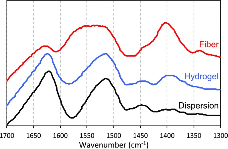
To confirm that the molecular structure of the PNFs stays intact during fiber formation, we acquired FTIR spectra in amide I and amide II band regions that report on the protein secondary structures (31). The amide I and II bands are centered at 1,625 cm−1 and 1,517 cm−1, respectively (Fig. S5), which is in agreement with a high content of β-sheet structure. The spectrum of the acetate-induced hydrogel is essentially the same as that of the PNF dispersion at pH 2. However, for the solid fiber made from curved PNFs in the flow-focusing geometry, the amide II band becomes broader, and the peak center is shifted to 1,550 cm−1. This change most likely originates from a higher content of acetate in the fiber sample. Increased spectral intensity at ∼1,400 cm−1 (Fig. S5), where acetate has another absorption peak, supports this hypothesis. The β-sheet core of the PNFs is, however, intact as the peak position of amide I band is unchanged.
Fig. S5.
FTIR spectrum of nongelled PNF dispersion, hydrogel, and dried fiber obtained from curved fibrils. The peaks at 1,625 and 1,517 cm−1 correspond to the amide I and II bands of proteins, respectively, which are related to the secondary structure. Increased intensity at 1,400 cm−1 for the dry fibers suggests that they contain a higher relative amount of acetate than the hydrogel.
Implications for the Design of Hierarchical PNF-Based Materials.
In many other systems, the alignment of nanofibrils (of any origin) provides an opportunity to improve mechanical properties. For example, alignment of cellulose nanofibrils using a similar device as in this study resulted in filaments with superior mechanical properties (13). The results presented here show the opposite effect for PNFs. Although the size and shape of PNFs and cellulose nanofibrils might appear similar, the structural and chemical properties of these nanostructures are indeed different. The origins of the materials further elucidate the differences. Cellulose nanofibrils from wood are extracted through chemical pretreatment followed by mechanical decomposition of cellulose, which refers to their intrinsic crystallinity and ability to form higher-order structures, e.g. in trees. PNFs, on the other hand, are self-assembled from protein monomers that might not correspond to any higher-order structures that already exist in nature. Hence, despite the similarities in size and aspect ratio, PNFs and cellulose nanofibrils are distinct classes of nanomaterials with essentially different behavior during assembly into macroscopic materials.
Interestingly, our results suggest some similarities between the formation of PNF microfibers and the assembly mechanism of recombinant spider silk proteins (16). Like the PNFs, spider silk has a high degree of β-sheet secondary structure and the fibers are formed in a spinning process based on elongational flow and pH alterations (32). However, the structural characteristics are different as the silk fibers contain significant parts that are disordered and the orientation of the β-sheets relative to the fiber axis is perpendicular to that expected for aligned PNFs (33). From this perspective, it is interesting that the lower degree of fibril alignment associated with the curved PNFs resulted in a stronger microfiber. Furthermore, the assembly process of spider silk also differs from our system because the molecular- and supramolecular structures are formed simultaneously during the spinning process. This allows for formation of entangled structures with optimized intermolecular interactions at the same time as highly ordered β-sheet regions are created. The present study shows that sufficient balance between ordered regions and interchain entanglements to create a coherent fiber can be achieved also with preformed β-sheet elements. Considering that not even artificially assembled silk fibers reach the same mechanical performance as natural silk, it is indeed fascinating that we can produce pure protein fibers from a rather crude raw material and with a fairly simple experimental setup. Further exploration of processing conditions and/or protein building blocks will elucidate the parameter space (mechanical entanglements, fibril orientation, spatial distribution of fibrils and chemical bonds) of PNF assembly in detail and provide the basis for design of novel materials with tailored properties.
Methods
Preparation of PNFs.
WPI (Lacprodan Di-9224) was kindly provided by Arla Food Ingredients. PNFs formed in the solution during incubation at 90 °C for 3 d. Concentrations of 40 g/L or 75–80 g/L were used to obtain straight and curved PNFs, respectively. The PNF solutions were dialyzed using a 100-kDa molecular weight cutoff for 7 d. The concentration of the straight fibrils was increased by centrifugal membrane filtration (100-kDa cutoff).
Atomic Force Microscopy.
PNF morphology was investigated using a Dimension FastScan atomic force microscope (AFM) (Bruker) operating in tapping mode. Samples were diluted between 1:500 and 1:10,000 in 0.01 M HCl and applied on a freshly cleaved mica surface. End-to-end lengths and the contour lengths of the fibrils were measured from AFM images using Image J software. At least 300 fibrils were measured for each fibril morphology. Calculations of persistence lengths and estimation of elastic moduli is described in SI Methods.
Flow-Focusing Setup and Fiber Formation.
The flow setup (13, 27) is described in Fig. S1. The flow rates were 4.1 mL/h for the core flow, and 4.7 mL/h and 24.9 mL/h for the first and second sheath flows, respectively. For the second sheath flow and bath solution, sodium acetate buffer at a pH of 5.2 was used. After spinning, hydrogel fibers were extracted from the bath and dried at room temperature for 2 h (Fig. S3) to obtain solid fibers.
Fiber Characterization.
The sample for SEM was prepared by sputtering a 10-nm gold–palladium layer on the dried fiber. SEM images were acquired with a Hitachi S-4800 Field-Emission SEM operating at an acceleration voltage of 1.0 kV.
For fluorescence microscopy, the obtained fiber was dipped in 120 μM thioflavin T solution and then dried at room temperature. The fiber was investigated using an inverted Nikon Eclipse Ti fluorescence microscope with excitation at 455−490 nm and emission at 500−540 nm.
Tensile tests were carried out using a Deben Micro tester with a 2.0-N load cell. The length and cross-section of each fiber were measured by an optical microscope.
FTIR spectroscopy was recorded in the frequency range of 600–4,000 cm−1 using a Bruker Tensor instrument.
In Situ μSAXS Measurements.
μSAXS measurements were performed at the P03 beamline, at the PETRAIII storage ring at Deutsches Elektronen-Synchrotron (DESY) (29). A slightly modified flow setup was used, where the second focusing step is mimicked by the contraction step. The flow rates were the same as the ones used for core flow and first sheath flow for the fiber formation. To quantify the alignment of PNFs, order parameters were calculated from μSAXS scattering patterns using a similar method as previously reported (13).
Rheology.
Rheology measurements of the PNF dispersions were carried out at room temperature using a DHR-2 rheometer (TA Instruments). After placing 300 μL of dispersion between the plates, 1 mL of pH 5.2 acetate buffer was added along the circumference to attain gelation.
SI Methods
Preparation of PNFs.
WPI (Lacprodan Di-9224) was kindly provided by Arla Food Ingredients. WPI corresponding to a concentration of ∼100 g/L was dissolved in 0.1 M (pH 1) hydrochloric acid (HCl) (Fisher Scientific) and the solution was dialyzed against 0.01 M HCl (pH 2) for 24 h at room temperature using a membrane (Spectrum Laboratories) with 6–8-kDa molecular weight cutoff. The solution was then diluted to desired concentrations: 40 g/L to obtain straight PNFs (Fig. 1A) or 75–80 g/L to obtain curved fibrils (Fig. 1B). PNFs formed in the solution during incubation at 90 °C for a period of 3 d. To remove nonfibrillated proteins, the PNF solution was dialyzed using a 100-kDa molecular weight cutoff membrane (Spectrum Laboratories) for 7 d. For straight fibrils, the concentration was increased by centrifugal membrane filtration (100-kDa cutoff membrane, GE Healthcare), until the desired concentration was achieved. The final concentrations were measured by UV absorbance (at 280 nm; relative concentrations of the samples) and dry weight measurements of lyophilized materials. Both the methods showed similar values of protein concentrations.
Atomic Force Microscopy.
PNF morphology was investigated using a Dimension FastScan AFM (Bruker) operating in tapping mode. Samples were diluted between 1:500 and 1:10,000 in 0.01 M HCl and 25 μL was applied on a freshly cleaved mica surface. The samples were then dried in air and investigated immediately. FastScan A cantilevers (Bruker) were used for the experiments and the images were investigated in Nanoscope 1.5 software. Control experiments were also performed in liquid using ScanAsyst Liquid+ cantilevers (Bruker) operating in Peak Force mode. These experiments showed the same difference between the morphologies of straight and curved PNFs.
To assess the difference of fibril morphology, the end-to-end lengths and the contour lengths of the fibrils were measured from AFM images using Image J software. Persistence length was calculated based on the assumption that the fibrils interact weakly with the mica surface and are able to relax to 2D equilibrium (34). The data points of Fig. 1C were fitted to the following expression:
where E is end-to-end length and C is contour length measured from AFM images, and P is persistence length calculated here. For this calculation, at least 300 fibrils were measured for each fibril morphology.
The calculated persistence lengths and measured fibril heights were used to derive a rough estimate of the relative elastic moduli of the PNFs. The elastic modulus is proportional to the persistence length (P), and inversely proportional to the area moment of inertia (I). Assuming a circular cross-section with an area moment of inertia I0 of the curved fibrils and that the straight fibrils are build from n twisted filaments, each with the same cross-section as the curved fibrils, we can approximate the area moment of inertia of the straight fibrils as I ∼ nI0 because bending mainly occurs according to the lowest energy mode (25, 26).
Bulk Gel Transition Experiments.
The PNF dispersions were gelled in a cuvette by adding sodium acetate (Sigma-Aldrich) buffer with pH values between 4.0 and 5.6. At an optimized pH value, the cuvette was inverted after gelation and gelling ability was accessed as the ability of the gels to remain at the top of the cuvette (Fig. 1 C and D).
Flow-Focusing Setup and Fiber Formation.
The flow setup consists of three syringe pumps (WPI, Al-4000), a flow-focusing channel (27), and a bath for the outlet of protein hydrogel fibers (Fig. S1). Syringe pumps were used to control the flow rates of the core and sheath flows. The flow rates used in this study were 4.1 mL/h for the core flow, and 4.7 mL/h and 24.9 mL/h for the first and second sheath flows, respectively. The flow channel was milled in a 1-mm-thick stainless steel plate and sandwiched between two Plexiglas plates (Fig. S1). Over the Plexiglas plates, two aluminum plates were placed on either side and screwed together to prevent leakage. All of the channels in the flow-focusing geometry were 1 mm in width. For the second sheath flow and bath solution, sodium acetate buffer at a pH of 5.2 was used. The outlet of the channel was submerged into the bath solution. After spinning, hydrogel fibers from the bath were extracted with the help of tweezers and then dried at room temperature for a period of 2 h (Fig. S3). Solid fibers were obtained after drying the hydrogel fibers.
Fiber Characterization.
The sample for SEM was prepared by sputtering a 10-nm gold–palladium layer (Gressington Instruments Ltd.) on the dried fiber. SEM images were acquired with a Hitachi S-4800 Field Emission SEM (Hitachi, Japan) operating at an acceleration voltage of 1.0 kV.
For fluorescence microscopy, the amyloidophilic dye thioflavin T (Sigma-Aldrich) was used. The obtained fiber was dipped in 120 μM thioflavin T solution and then dried at room temperature. Fluorescence microscopy investigations of the fiber were carried out using an inverted Nikon Eclipse Ti fluorescence microscope with excitation at 455−490 nm and emission at 500−540 nm.
Tensile tests were carried out using a Deben Micro tester with a 2.0-N load cell. The length and cross-section of each fiber were measured by an optical microscope. The span length of fibers tested was 8–10 mm and measurements were performed at a pulling rate of 0.6 mm min−1.
FTIR spectroscopy was recorded in the frequency range of 600–4,000 cm−1 using a Bruker Tensor instrument.
In Situ μSAXS Measurements.
μSAXS measurements were performed at the P03 beamline at the PETRAIII storage ring at DESY in Hamburg, Germany (29). The measurements were performed in a transmission geometry with an X-ray wavelength λ = 0.95 Å and sample-to-detector distance of 6950 mm. The scattering patterns were recorded by a single-photon counting detector (Pilatus 1M, Dectris) with the pixel size of 172 × 172 μm2. The beam size was 20 × 10 μm2 (horizontal × vertical). For the in situ μSAXS study, a slightly modified flow setup was used where the second focusing step is mimicked by the contraction step, which works on the same principle of elongational flow field. The flow rates were the same as the ones used for core flow and first sheath flow for the fiber formation. The flow-focusing channel was sandwiched between two Kapton sheets instead of Plexiglas plates that were used for the fiber formation experiments.
To quantify the alignment of PNFs, order parameters were calculated from μSAXS scattering patterns using a similar method as reported by Håkansson et al. (13). In brief, the scattering patterns were first transformed into the diffractogram with scattering vector q [defined as q = 4πsin(θ)/λ, where 2θ is scattering angle] and azimuthal angle φ as coordinates. The background intensity of a flow with pure water was subtracted from the intensity of protein samples, with the normalization of the maximum intensity. To calculate order parameter, the intensity of isotropic contribution was removed under the assumption that the highest aligned case shows the intensity of the isotropic distribution of PNFs in the nonaligned direction. Then the intensity distribution was averaged for 0.1 < q < 0.5 nm−1 for each azimuthal angle. The alignment of PNFs was quantified by order parameter (S) (35), defined as
Expanding the average gives
which is normalized according to
where is the intensity distribution averaged along the examined q range for each azimuthal angle.
Rheology.
Rheology measurements to investigate the viscoelastic properties of the PNF dispersions and hydrogels were carried out at room temperature using a DHR-2 rheometer (TA Instruments) equipped with a Peltier plate for temperature control and a 25-mm-diameter parallel plate setup with a truncation gap of 500 μm. After placing 300 μL of dispersion between the plates, 1 mL of pH 5.2 acetate buffer was added along the circumference to attain gelation. Subsequently, 0.25% strain was applied and measurements of storage and loss modulus were carried out for a period of 50 min (until the time a constant measurement value was reached). After that, fractured stress was measured with increasing strain from 0.01% to 60% at a constant frequency of 1 Hz.
Acknowledgments
We thank Tomas Rosén, Matthew Fielden, Lilian Medina, Qiliang Fu, Qiong Wu, Farhan Ansari, and Ronnie Jansson for their contributions. This work was supported by Formas Grant 213-2014-1389 (to C.L.), Magnus Bergvalls Stiftelse, and the Wallenberg Wood Science Center. A.K. acknowledges the support by Japan Public-Private Partnership Student Study Abroad Program.
Footnotes
The authors declare no conflict of interest.
This article is a PNAS Direct Submission.
This article contains supporting information online at www.pnas.org/lookup/suppl/doi:10.1073/pnas.1617260114/-/DCSupplemental.
References
- 1.Meyers MA, McKittrick J, Chen PY. Structural biological materials: Critical mechanics-materials connections. Science. 2013;339(6121):773–779. doi: 10.1126/science.1220854. [DOI] [PubMed] [Google Scholar]
- 2.Knowles TPJ, Buehler MJ. Nanomechanics of functional and pathological amyloid materials. Nat Nanotechnol. 2011;6(8):469–479. doi: 10.1038/nnano.2011.102. [DOI] [PubMed] [Google Scholar]
- 3.Knowles TP, Mezzenga R. Amyloid fibrils as building blocks for natural and artificial functional materials. Adv Mater. 2016;28(31):6546–6561. doi: 10.1002/adma.201505961. [DOI] [PubMed] [Google Scholar]
- 4.Chiti F, Dobson CM. Protein misfolding, functional amyloid, and human disease. Annu Rev Biochem. 2006;75:333–366. doi: 10.1146/annurev.biochem.75.101304.123901. [DOI] [PubMed] [Google Scholar]
- 5.Kavanagh GM, Clark AH, Ross-Murphy SB. Heat-induced gelation of globular proteins: Part 3. Molecular studies on low pH β-lactoglobulin gels. Int J Biol Macromol. 2000;28(1):41–50. doi: 10.1016/s0141-8130(00)00144-6. [DOI] [PubMed] [Google Scholar]
- 6.Krebs MR, et al. Formation and seeding of amyloid fibrils from wild-type hen lysozyme and a peptide fragment from the β-domain. J Mol Biol. 2000;300(3):541–549. doi: 10.1006/jmbi.2000.3862. [DOI] [PubMed] [Google Scholar]
- 7.Akkermans C, et al. Micrometer-sized fibrillar protein aggregates from soy glycinin and soy protein isolate. J Agric Food Chem. 2007;55(24):9877–9882. doi: 10.1021/jf0718897. [DOI] [PubMed] [Google Scholar]
- 8.Knowles TP, et al. Role of intermolecular forces in defining material properties of protein nanofibrils. Science. 2007;318(5858):1900–1903. doi: 10.1126/science.1150057. [DOI] [PubMed] [Google Scholar]
- 9.Usov I, Adamcik J, Mezzenga R. Polymorphism complexity and handedness inversion in serum albumin amyloid fibrils. ACS Nano. 2013;7(12):10465–10474. doi: 10.1021/nn404886k. [DOI] [PubMed] [Google Scholar]
- 10.vandenAkker CC, Engel MF, Velikov KP, Bonn M, Koenderink GH. Morphology and persistence length of amyloid fibrils are correlated to peptide molecular structure. J Am Chem Soc. 2011;133(45):18030–18033. doi: 10.1021/ja206513r. [DOI] [PubMed] [Google Scholar]
- 11.Bolisetty S, Harnau L, Jung JM, Mezzenga R. Gelation, phase behavior, and dynamics of β-lactoglobulin amyloid fibrils at varying concentrations and ionic strengths. Biomacromolecules. 2012;13(10):3241–3252. doi: 10.1021/bm301005w. [DOI] [PubMed] [Google Scholar]
- 12.Davis VA, et al. True solutions of single-walled carbon nanotubes for assembly into macroscopic materials. Nat Nanotechnol. 2009;4(12):830–834. doi: 10.1038/nnano.2009.302. [DOI] [PubMed] [Google Scholar]
- 13.Håkansson KMO, et al. Hydrodynamic alignment and assembly of nanofibrils resulting in strong cellulose filaments. Nat Commun. 2014;5:4018. doi: 10.1038/ncomms5018. [DOI] [PMC free article] [PubMed] [Google Scholar]
- 14.Kiriya D, Kawano R, Onoe H, Takeuchi S. Microfluidic control of the internal morphology in nanofiber-based macroscopic cables. Angew Chem Int Ed Engl. 2012;51(32):7942–7947. doi: 10.1002/anie.201202078. [DOI] [PubMed] [Google Scholar]
- 15.Köster S, Evans HM, Wong JY, Pfohl T. An in situ study of collagen self-assembly processes. Biomacromolecules. 2008;9(1):199–207. doi: 10.1021/bm700973t. [DOI] [PMC free article] [PubMed] [Google Scholar]
- 16.Rammensee S, Slotta U, Scheibel T, Bausch AR. Assembly mechanism of recombinant spider silk proteins. Proc Natl Acad Sci USA. 2008;105(18):6590–6595. doi: 10.1073/pnas.0709246105. [DOI] [PMC free article] [PubMed] [Google Scholar]
- 17.Saldanha O, Brennich ME, Burghammer M, Herrmann H, Köster S. The filament forming reactions of vimentin tetramers studied in a serial-inlet microflow device by small angle x-ray scattering. Biomicrofluidics. 2016;10(2):024108. doi: 10.1063/1.4943916. [DOI] [PMC free article] [PubMed] [Google Scholar]
- 18.Trebbin M, et al. Anisotropic particles align perpendicular to the flow direction in narrow microchannels. Proc Natl Acad Sci USA. 2013;110(17):6706–6711. doi: 10.1073/pnas.1219340110. [DOI] [PMC free article] [PubMed] [Google Scholar]
- 19.Lutz-Bueno V, et al. Scanning-SAXS of microfluidic flows: nanostructural mapping of soft matter. Lab Chip. 2016;16(20):4028–4035. doi: 10.1039/c6lc00690f. [DOI] [PubMed] [Google Scholar]
- 20.Hamada D, Dobson CM. A kinetic study of β-lactoglobulin amyloid fibril formation promoted by urea. Protein Sci. 2002;11(10):2417–2426. doi: 10.1110/ps.0217702. [DOI] [PMC free article] [PubMed] [Google Scholar]
- 21.Gosal WS, Clark AH, Ross-Murphy SB. Fibrillar β-lactoglobulin gels: Part 1. Fibril formation and structure. Biomacromolecules. 2004;5(6):2408–2419. doi: 10.1021/bm049659d. [DOI] [PubMed] [Google Scholar]
- 22.Veerman C, Ruis H, Sagis LMC, van der Linden E. Effect of electrostatic interactions on the percolation concentration of fibrillar β-lactoglobulin gels. Biomacromolecules. 2002;3(4):869–873. doi: 10.1021/bm025533+. [DOI] [PubMed] [Google Scholar]
- 23.Akkermans C, et al. Peptides are building blocks of heat-induced fibrillar protein aggregates of β-lactoglobulin formed at pH 2. Biomacromolecules. 2008;9(5):1474–1479. doi: 10.1021/bm7014224. [DOI] [PubMed] [Google Scholar]
- 24.Bolder SG, Hendrickx H, Sagis LMC, van der Linden E. Fibril assemblies in aqueous whey protein mixtures. J Agric Food Chem. 2006;54(12):4229–4234. doi: 10.1021/jf060606s. [DOI] [PubMed] [Google Scholar]
- 25.Adamcik J, et al. Understanding amyloid aggregation by statistical analysis of atomic force microscopy images. Nat Nanotechnol. 2010;5(6):423–428. doi: 10.1038/nnano.2010.59. [DOI] [PubMed] [Google Scholar]
- 26.Adamcik J, Berquand A, Mezzenga R. Single-step direct measurement of amyloid fibrils stiffness by peak force quantitative nanomechanical atomic force microscopy. Appl Phys Lett. 2011;98:1937901. [Google Scholar]
- 27.Håkansson KMO. Online determination of anisotropy during cellulose nanofibril assembly in a flow focusing device. RSC Advances. 2015;5:18601–18608. [Google Scholar]
- 28.Knowles TPJ, Oppenheim TW, Buell AK, Chirgadze DY, Welland ME. Nanostructured films from hierarchical self-assembly of amyloidogenic proteins. Nat Nanotechnol. 2010;5(3):204–207. doi: 10.1038/nnano.2010.26. [DOI] [PMC free article] [PubMed] [Google Scholar]
- 29.Buffet A, et al. P03, the microfocus and nanofocus X-ray scattering (MiNaXS) beamline of the PETRA III storage ring: The microfocus endstation. J Synchrotron Radiat. 2012;19(Pt 4):647–653. doi: 10.1107/S0909049512016895. [DOI] [PMC free article] [PubMed] [Google Scholar]
- 30.Jordens S, Isa L, Usov I, Mezzenga R. Non-equilibrium nature of two-dimensional isotropic and nematic coexistence in amyloid fibrils at liquid interfaces. Nat Commun. 2013;4:1917. doi: 10.1038/ncomms2911. [DOI] [PubMed] [Google Scholar]
- 31.Barth A. Infrared spectroscopy of proteins. Biochim Biophys Acta. 2007;1767(9):1073–1101. doi: 10.1016/j.bbabio.2007.06.004. [DOI] [PubMed] [Google Scholar]
- 32.Rising A, Johansson J. Toward spinning artificial spider silk. Nat Chem Biol. 2015;11(5):309–315. doi: 10.1038/nchembio.1789. [DOI] [PubMed] [Google Scholar]
- 33.Ling S, et al. Modulating materials by orthogonally oriented β-strands: Composites of amyloid and silk fibroin fibrils. Adv Mater. 2014;26(26):4569–4574. doi: 10.1002/adma.201400730. [DOI] [PubMed] [Google Scholar]
- 34.Gosal WS, et al. Competing pathways determine fibril morphology in the self-assembly of β2-microglobulin into amyloid. J Mol Biol. 2005;351(4):850–864. doi: 10.1016/j.jmb.2005.06.040. [DOI] [PubMed] [Google Scholar]
- 35.van Gurp M. The use of rotation matrices in the mathematical description of molecular orientations in polymers. Colloid Polym Sci. 1995;273:607–625. [Google Scholar]


