Abstract
Several membrane proteins and numerous membrane-active peptides have been studied in detergent micelles by solution NMR. However, the detailed structure of these complexes remains unknown. We propose a modeling approach that treats the protein and detergent in atomistic detail and the solvent implicitly. The model is based on previous work on dodecylphosphocholine micelles, adapted for use with the CHARMM36 force field and extended to sodium dodecyl sulfate micelles. Solvation parameters were slightly adjusted to reproduce experimental data on aggregation numbers and critical micelle concentrations. To test the approach, several membrane-active peptides and three β-barrel membrane proteins were subjected to molecular dynamics simulations in the presence of a large number of detergent molecules. Their experimentally determined secondary structure was maintained and the RMSD values were less than 2 Å. Deformations were commonly observed in the N or C termini. The atomistic view of the protein-micelle systems that this approach provides could be useful in interpreting biophysical experiments carried out in the presence of detergent.
Keywords: Micelles, detergent, surfactant, DPC, SDS, molecular dynamics, aggregation number, critical micelle concentration, membrane proteins
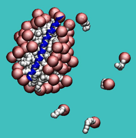
Graphical Abstract
INTRODUCTION
Membrane proteins are difficult to study experimentally due to the hydrophobic nature of their surface1. The native bilayer environment is not conducive to crystallization or solution NMR studies, which thus requires an alternative membrane-mimetic environment that maintains protein stability and function2. Different types of systems have been designed for this purpose, including detergent micelles, bicelles, small vesicles, or nanodiscs3. Due to their small size and low cost, detergents are widely used in membrane protein structural biology4 but also in various technological areas, such as the pharmaceutical and food industry, cosmetics, etc.
Detergents are amphiphilic molecules that self-assemble in water to form aggregates (micelles) in which the hydrophobic tails come together to minimize contact with water. This occurs above a specific surfactant concentration known as the critical micelle concentration (CMC). Micelles can have different sizes and shapes such as spherical, ellipsoidal, rod-like or worm-like, etc. Micelle size is thought to be determined by a balance between two opposing forces: the attractive hydrophobic interactions among tails and the repulsive electrostatic interactions among head groups5. Micelle size and shape is also affected by surfactant concentration, temperature, and ionic strength6. The number of molecules in a micelle is called the aggregation number7 and can vary from 4 to a few hundred. It is calculated experimentally by sedimentation equilibrium, light8 or neutron9 scattering and time resolved fluorescence quenching10.
Micelles can be classified according to the nature of their head group as anionic, e.g. sodium dodecyl sulfate (SDS); cationic, e.g. CTAB; zwitterionic, e.g. dodecylphosphocholine (DPC), CHAPS, or DHPC; and nonionic, e.g. octyl glucoside. The most commonly used detergents in structural biology are DPC, mimicking zwitterionic eukaryotic membranes; and SDS, mimicking anionic prokaryotic membranes. These two systems have helped to elucidate the structure of several membrane proteins and numerous membrane-active peptides. Because of the different headgroup chemistry, curvature, and shape, each micelle provides a different environment for proteins. Finding the correct match between protein and detergent is still a largely empirical art. In addition, the extent to which a micelle can mimic a bilayer is a common concern1,2. Although NMR can measure some peptide-lipid NOEs11 and paramagnetic resonance enhancement provides information on the location of the peptide within the micelle12, the structure of a protein-detergent complex is not known in atomic detail.
All-atom molecular dynamics (MD) simulations provide an alternative avenue for obtaining structural details on micelles13–15. Several investigations focused on pure SDS16–21 or DPC22–25 micelles as well as micelle-peptide complexes26,27. Most studies started from a preformed micelle, while a few examined the spontaneous aggregation of surfactants into pure micelles22 or peptide-micelle complexes28. Coarse-grained models have also been designed for lipids and surfactants29–32; these are more computationally efficient and offer the opportunity to study larger systems and longer time scale processes.
An alternative approach in the direction of computational efficiency is to treat the water implicitly. Our group developed such a model for pure DPC micelles33 by treating the surfactant in atomistic detail and the solvent implicitly in the spirit of the EEF1 energy function for proteins34. That approach allowed the calculation of statistical properties such as CMC, aggregation number and micelle size distribution. Other groups took a similar approach using different implicit water models and sampling techniques35–37.
Here, we extend this approach to SDS micelles and to peptide-micelle complexes. In order to use the new CHARMM36 force field, a slight adjustment was also required in the DPC model. Simulations of a large number of detergent molecules (~1000) were used to determine aggregation numbers and CMC values. The model parameters were adjusted to reproduce experimental values for these properties. To assess the validity of the resulting models and to gain insight into peptide/micelle interactions, molecular dynamics simulations of several peptides in SDS and DPC micelles were performed. In all cases their structures remained close to the experimental ones.
METHODS
All molecular dynamics (MD) simulations were performed using the CHARMM program38 and the CHARMM3639,40 topology and parameter files for proteins and lipids. The interaction of each atom with the solvent was described implicitly with the EEF1 energy function34. EEF1 uses a nonbonded cutoff of 9 Å with a switching function activated at 7 Å. All MD simulations were run using the Verlet integrator with a 2 fs time step and the SHAKE algorithm to constrain the length of bonds involving hydrogen. The temperature was kept constant at 300 K and the velocities were scaled if the average temperature deviated from 300 K by more than 5 K.
The EEF1 solvation parameters for DPC were based on previous work33, with a slight modification for phosphorus (see Results). The model for the SDS molecule was built in analogy to DPC. The solvation parameters for the alkyl chain were the same. In the spirit of the EEF1 model, the net negative charge of SDS was removed. To select the optimal distribution of partial charges in the SDS head group, the potential of mean force was calculated between two dimethyl sulfate ions in explicit water (see below). Subsequently, a large number of detergents was simulated to observe the self-assembly and to calculate aggregation numbers and the CMC (see below). The solvation parameters of the two types of oxygen were then adjusted to reproduce the experimental aggregation numbers.
Calculation of the Potential of Mean Force in explicit water
The potential of mean force (PMF) between two dimethyl sulfate ions was calculated using umbrella sampling41. A sphere of water containing 1653 TIP3P water molecules (radius ~23 Å) was centered at the midpoint between the two sulfur atoms. A Spherical Solvent Boundary Potential (SSBP)42 was applied to the water molecules to reproduce the effect of bulk water at constant pressure. The calculations were performed with the center of mass of the two sulfur and the two ester-like oxygen atoms harmonically constrained to the center of the sphere using the GEO command in the CHARMM program.
Initial structures were generated by translation along the axis joining the sulfur atoms of each dimethyl sulfate molecule from 3.5 to 14 Å at a 0.25 Å increment. Initially the umbrella force constant was set to 1 kcal/Å2, but in some cases this value was found to be insufficient to sample high energy regions, and additional simulations under the same conditions were performed with a higher force constant of 4, 7 or 9 kcal/Å2. A molecular dynamics simulation of 200 ps was performed for each window. To reconstruct the full distribution function the weighted histogram analysis method (WHAM)43 was used using the WHAM 2.0.4 software44. The PMF was also calculated using the EEF1 energy function in the same range (3.5 to 14 Å) by simple energy evaluations.
MD simulations of detergent solutions at finite concentrations
To simulate specific detergent concentrations, the MMFP module of CHARMM was used to constrain the detergent molecules within a sphere of the appropriate radius with a force constant of 5 kcal/mol. 960 DPC molecules or 1000 SDS molecules were placed randomly inside a sphere with radius 266 Å (20 mM) for DPC and 199 Å (50 mM) for SDS. The system was simulated at 800 K for 100 ps to produce a uniform distribution of the detergent molecules within the sphere. This initial configuration was further simulated at 300 K for 10 ns to allow micelle self assembly, as in previous work33. The last 2 ns for the DPC system and the last 3 ns for the SDS system were used to calculate the weight average aggregation number (Nw) and the number average aggregation number (Nn) according to the equations7,45:
where Hi is the number of micelles composed by i surfactants. As in previous work, a micelle is defined as a cluster of surfactants each of which has its center of mass within 15 Å from any of the others33. Any molecule that does not belong to a cluster is counted as a monomer. The number of monomers is denoted as Nmon. The CMC is taken to be equal to the concentration of monomers (Nmon/volume)46 at the lowest simulated total surfactant concentration.
The determination of micelle shape was performed on the last frame of the 10-ns simulations. The bioinformatics tools of the visualization program VMD47 were used to calculate the radius of gyration of each micelle individually and the ratios of the three principal moments of inertia (I1/I2 and I1/I3).
MD simulations of micelle-protein systems
All systems were chosen from the RCSB protein database, as shown in Table 1. They can be classified into three groups: 1) Single helices, such as the W-rich domain of HIV gp41, magainin 2, antimicrobial RP-1, hemagglutinin fusion domain, and NBAR domain H0 helix; 2) Helix – loop – helix structures, such as maximin-4 and phospholamban; 3) β–sheet structures, such as P-type Cardiotoxin, OMPX, OMPA and OMPG.
Table 1.
Peptide-micelle systems studied
| PROTEIN DOMAIN | PDB ID | DETERGENT |
|---|---|---|
| Magainin 2 | 2MAG / 2LSA | DPC / SDS |
| Antimicrobial RP-1 | 2RLH / 2RLG | DPC / SDS |
| W-rich HIV GP41 | 1JAV | DPC |
| Hemagglutinin Fusion | 1IBO / 1IBN | DPC |
| Phospholamban | 1N7L | DPC |
| Maximin-4 | 2MHW | SDS |
| NBar H0 | 2RMY | SDS |
| P-type Cardiotoxin | 1FFJ | DPC |
| OMPX | 1Q9F | DPC |
| OMPA | 1G90 | DPC |
| OMPG | 2JQY | DPC |
A sphere of 50 Å radius was filled with a number of detergent molecules that roughly corresponds to the aggregation number of the surfactant and to a concentration close to the experimental value (~150 mM). 64 or 72 detergent molecules, for DPC and SDS respectively, were distributed randomly in the sphere, as described above. The peptide/protein was placed in the middle of this ensemble and clashes with the lipid molecules were removed by deleting the overlapping lipid molecules (this is why the number of surfactant molecules varies in each system). Position restraints were placed on the protein and a 1-ns MD simulation was launched to allow the lipids to redistribute around the protein. After 1 ns, the protein was released and additional 5 ns of MD simulation was run. The EEF1 solvation parameters for the detergent systems were added to the standard EEF1 solvation parameters for proteins in water. Protein – micelle system size and shape were determined as described above.
RESULTS
Adaptation of the DPC model to the Charmm 36 force field
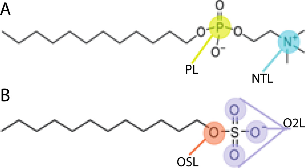
Previous work from this group was based on the CHARMM27 all-atom lipid parameters48 and placed the solvation free energy parameters on the nitrogen and phosphorus atoms of the phophocholine head group (Fig. 1A and Table 2). Using those parameters with the newer CHARMM36 force field39 gave lower aggregation numbers (Nn = 18; Nw = 31) and higher CMC (4.2 mM) than those obtained originally (Nn = 35 ; Nw = 53; CMC = 1.25 mM)33. This may be attributed to the Lennard-Jones parameters for OSL/OSLP that were modified from ε = −0.1521 and Rmin/2 = 1.77 in CHARMM27 to ε = −0.1 and Rmin/2 = 1.65 in CHARMM36. Additionally, the CHARMM36 force field added a new atom type for a lipid phosphate ester oxygen (OSLP), which contains the same bonded and nonbonded parameters as the regular nucleic acid phosphate ester oxygen for lipids (OSL) that CHARMM27 uses, differing only in a few dihedral values.
Figure 1.
Cartoon representation of A) DPC molecule and B) SDS molecule showing the particles types where the solvation free energy parameters were assigned.
Table 2.
Previous and current solvation parameters of the DPC head group
| ATOM NAME |
ATOM TYPE |
OLD SOLV PARAM. Gfree (Kcal/mol) |
NEW SOLV PARAM. Gfree (Kcal/mol) |
|---|---|---|---|
| N | NTL | −26.00 | −26.00 |
| C11, C15 | CTL2 | 0.52 | 0.52 |
| C12, C13, C14 | CTL5 | 1.50 | 1.50 |
| P1 | PL | −24.00 | −19.00 |
| O3, O4 | O2L | 0.00 | 0.00 |
| O1, O2 | OSLP | 0.00 | 0.00 |
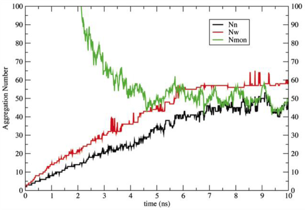
To rectify this problem, a small adjustment was made in the solvation free energy parameter of phosphorus in order to make it slightly less repulsive (Table 2)33. The new parameters were tested with a 10-ns simulation of 960 DPC molecules at 20 mM. The aggregation numbers and the number of monomers seem to converge at about 5.5 ns (Fig. 2), giving Nw ~ 52 ± 5, Nn ~ 40 ± 4, and Nmon ~ 52, corresponding to concentration 1.1 mM. These values are close to the experimental values of Nw (50–60 at 20 mM) and a CMC of 1.1 mM23,24. To check for dependence of the free monomer concentration on total surfactant concentration49, the simulation was repeated at 10 mM and gave free monomer concentration 1.6 ± 0.1 mM.
Figure 2.
Aggregation numbers (Nn black line, Nw red line), and number of monomers (Nmon green line) as a function of time for a 10-ns simulation of 960 DPC molecules with the new solvation parameters.
Model for SDS
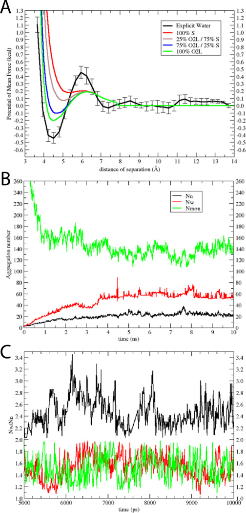
As a benchmark for developing an implicit water model for SDS (Fig. 1B), we computed the potential of mean force (PMF) between two methyl sulfate molecules in explicit solvent. This PMF is shown in Fig. 3A (black solid line). From 7 Å to 14 Å it is quite flat, with a minimum at ~4.5 Å at slightly negative energy (~ −0.45 kcal) and a slightly positive desolvation barrier (~ 0.45 kcal). The PMF curve shown in Fig. 3A is an average of four independent umbrella sampling calculations, in all of which the minimum ranged from −0.35 to −0.5 kcal/mol.Fig. 3A also shows several curves calculated with EEF1 with the negative partial charge distributed differently between the sulfur and oxygen atoms. The green curve, which corresponds to distribution of the charges equally to the O2L atoms, is closest to the atomistic result. This distribution was used in the rest of this work (Table 3). Partial justification for neutralizing the sulfate headgroup comes from the high degree of association of sodium counterions to the sulfate, which is approximately 75%16,18,50–55. Our model implicitly accounts for the effect of the sodium counterions. It should also be noted that SDS properties such as aggregation number56 or micelle shape57 are sensitive to salt; the present model pertains to zero salt concentration.
Figure 3.
Model for SDS: A) PMFs between two dimethyl sulfate ions in explicit water (black); error bars were obtained from four independent calculations. Also shown are results in implicit water, where the negative charge was distributed only on the S atom (red), 25% on the O2L atoms and 75% on the S atom (brown), 75 % on the O2L atoms and 25% on the S atom (blue), and only on the O2L atoms (green). B) Aggregation numbers (Nn black line, Nw red line), and number of monomers (Nmon green line) as a function of time for the 10-ns simulation of 1000 SDS molecules at 50 mM. C) Nw/Nn versus time for 50 mM (black), 200 mM (red) and 400 mM (green); only the converged last 5 ns are shown.
Table 3.
Charges and solvation parameters of the SDS head group
| ATOM NAME |
ATOM TYPE |
STANDARD CHARGES |
NEW CHARGES |
SOLV. PARAM. Gfree (Kcal/mol) |
|---|---|---|---|---|
| S | SL | 1.33 | 1.33 | 0.00 |
| OS1 | OSL | −0.28 | −0.28 | −9.34 |
| OS2, OS3, OS4 | O2L | −0.65 | −0.31667 | −8.66 |
| C1 | CTL2 | −0.28 | −0.28 | 0.52 |
The PMF curves presented in Fig. 3A use a solvation parameter for oxygen very close to the value of oxygen in water (~ −5.0). This value was modified (O2L = −8.7 and OSL = −9.3) (Table 3) until we obtained aggregation numbers and CMC very close to experimental values, NWfor 50 mM of 62 – 65 and CMC of 8 mM51,55,56,58,59. The averages of the converged part of the plot are Nw ~ 58 ± 5, Nn ~ 22 ± 3, and the free monomer concentration is 6.7 mM ± 0.6 (Nmon=134 ± 11) (Fig. 3B). The Nw/Nn ratio is greater than 1 (~2.6) indicating polydispersity (see Discussion). To check if this ratio and the free monomer concentration are affected by overall detergent concentration, three additional 10-ns simulations were performed at concentrations 20, 200 and 400 mM. The results show that the Nw/Nn ratio decreased from 3.1 ± 0.4 at 20 mM, to 2.6 ± 0.6 at 50 mM (Fig. 3C, black) to 1.6 ± 0.4 at 200 and 400 mM (Fig. 3C, red and green, respectively). The free monomer concentration increased from 3.5 ± 1 at 400 mM to 8.0 ± 0.3 at 20 mM. Thus the true CMC for this model should be somewhat higher than 8.0 mM.
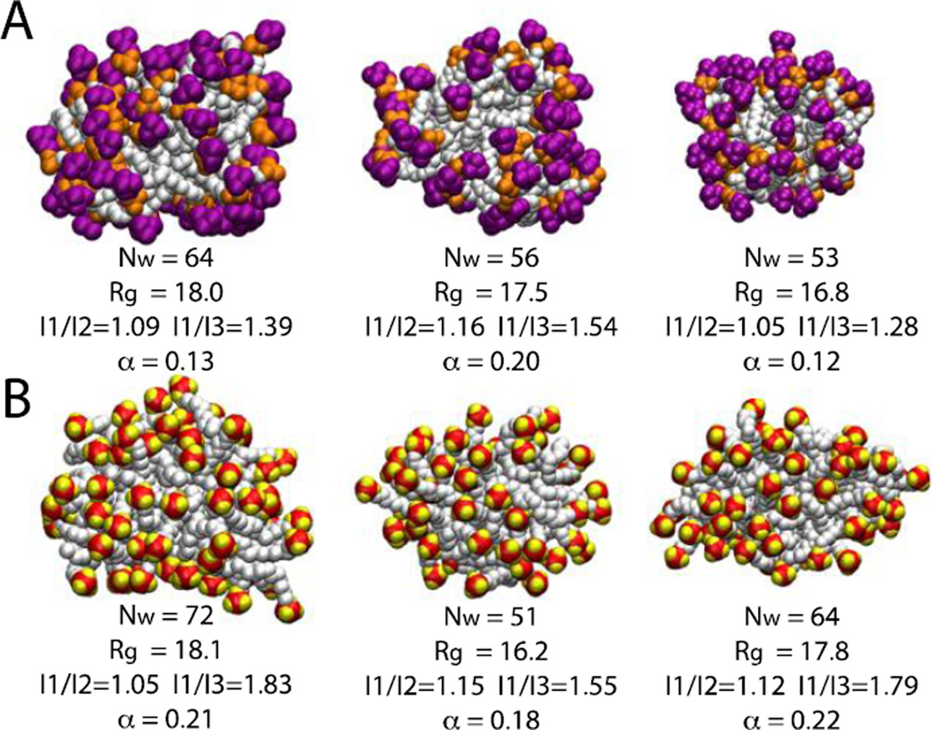
Values of some structural observables such as radius of gyration, aggregation number (Nw), ratios of moments of inertia (I1/I2 and I1/I3) and asymmetry parameter (α) were calculated for some representative micelles over the last four nanoseconds of the simulations (converged region of Fig. 2 and 3B). The radius of gyration varies between 16.5 Å to 18.2 Å for DPC and 15.5 Å to 18.2 Å for SDS micelles. For both micelle systems the ratio of moments of inertia varies from 1.02 (I1/I2) to 1.83 (I1/I3) and the asymmetry factor varies from 0.10 to 0.22 indicating that the micelles deviate significantly from spherical shape (Fig. 4).
Figure 4.
Snapshots of six randomly chosen micelles at 10 ns. A) DPC micelles; purple is the choline group and orange the phosphate group. B) SDS micelles; red is the sulfur atom and yellow the oxygen atom. Aggregation number, radius of gyration, ratios of moments of inertia and asymmetry parameter are given beneath each representation. The asymmetry parameter is defined as α = (2I1 – I2 – I3)/(I1 + I2+I3)23
Peptide-micelle systems
To test the validity of these models, several peptides and small proteins were simulated in the presence of detergents (Table 1). As a control, each system was simulated for 1 ns in pure implicit water, where they were found to be destabilized with RMSD values over 5 Å. In almost all helical systems, after 5 ns the protein was found on the micelle surface, more superficial in SDS than in DPC. More information on the position of each protein in the micelle can be found in Table 4. To check for reproducibility, three independent 5-ns simulations with different initial random velocities were performed on five systems: Magainin 2 and ARP1 in DPC and SDS micelles, and GP41 in a DCP micelle. The RMSD values of the three runs are very similar (see Fig. S1 and Table S1 in Supporting Information). Furthermore, to check the convergence, simulations of magainin 2 and ARP1 systems in DPC and SDS micelles were extended to 20 ns, showing similar RMSD values as the shorter simulations (Figs S1, S2 and S3).
Table 4.
Position of each protein in the micelle after 1 ns with constraints and 5 ns unconstrained.
| Protein | Type | # Lipids |
Position after 1 ns with constraints |
Position after 5 ns |
RMSD 5 ns (Å) |
Figure |
|---|---|---|---|---|---|---|
| Magainin2 | DPC | 41 | On the surface | On the surface | 1.2 | 5:B1,B2 |
| Magainin2 | SDS | 50 | On the surface | On the surface | 1.0 | 5:C1,C2 |
| ARP1 | DPC | 45 | Close to surface | On the surface | 1.0 | 6:B1,B2 |
| ARP1 | SDS | 55 | On the surface | On the surface | 1.2 | 6:C1,C2 |
| GP41 | DPC | 45 | On the surface | On the surface | 1.7 | 8:A2,A3 |
| Hemagglut. Fusion |
DPC | 46 | Helix inside micelle C-terminal outside |
On the surface | 0.8 | 9:B,C |
| Phospholamban | DPC | 65/ 131 |
Inside micelle | Helix A on the surface |
1.0 | 8:B2,B3 |
| P-Cardiotoxin | DPC | 62/ 128 |
Inside micelle | Inside micelle | 1.7 | 8:C2,C3 |
| Maximin 4 | SDS | 51 | On the surface | On the surface | 1.0 | 10:B,C,D,E |
| NBAR H0 | SDS | 48/71 | On the surface | On the surface | 1.5 | 11:B,C,D,E |
| OMPX | DPC | 70 | Inside micelle | Loops outside micelle |
1.9 | 12:A |
| OMPA | DPC | 67/ 109/ 230 |
Inside micelle | Inside micelle | 1.9 | 12:B1,B2,B3 |
| OMPG | DPC | 80/ 208 |
Inside micelle | Inside micelle | 1.9 | 10:C |
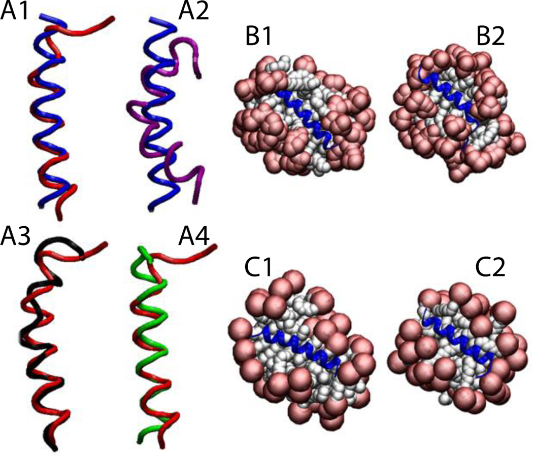
For Magainin 2 in DPC micelles (pdb id 2MAG), the micelle was formed around the protein, keeping the protein very close to the surface (Fig. 5-B1). Upon release of the constraints (Fig. 5-B2) the protein maintained its helical conformation with RMSD value, averaged over three independent 5-ns runs, of 1.1 ± 0.3 Å from the NMR structure, considering only the backbone of residues 4 to 20 (Fig. 5-A1). The same protein (2MAG) in SDS micelles (Fig. 5-C1,C2) maintained its helical conformation with an RMSD value, averaged over three 5-ns runs, of 1.0 ± 0.2 Å from the NMR structure (Fig. 5-A4). The reported structure of Magainin 2 in SDS micelles (pdb id 2LSA, an unpublished work where the experimental conditions are unknown) shows a curved helix (Fig. 5-A2). In the simulation, after the protein is released the helix adopts almost the same conformation as in DPC micelles with an RMSD of 0.8 Å for residues 4 to 20 (Fig. 5-A3). Gesell et al. obtained the same conformation for Magainin 2 in DPC or SDS micelles by NMR spectroscopy60.
Figure 5.
Cartoon representation of magainin 2: A1) Comparison of the NMR structure in DPC micelles (blue) versus final structure after 5 ns (red). A2) Comparison between two NMR structures in DPC (blue) and in SDS (2LSA) (purple). A3) Comparison between the peptides (2MAG and 2LSA) at the last frame of the 5-ns simulation without restraints in DPC (red) and in SDS (black). A4) Comparison between the peptides (2MAG) at the last frame of the 5-ns simulation without restraints in DPC (red) and in SDS (green). Representation of the protein-micelle system (2MAG) in DPC micelles after 1 ns with restraints (B1), and after 5 ns without restraints (B2), and in SDS micelles after 1 ns with restraint (C1) and 5 ns without restraints (C2). Head groups are depicted in red and tails in white.
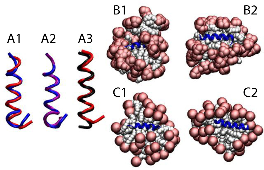
2RLH and 2RLG are the pdb IDs for the ARP1 peptide in DPC and SDS, respectively, both obtained using NMR spectroscopy61. The two structures are very similar with an RMSD value of 0.8 Å (Fig. 6-A2). In the DPC micelle, after 1 ns with restraints, the micelle assembled around the protein, placing the protein in a ‘flytrap’ pocket (Fig. 6-B1). In the SDS micelle, the protein was accommodated on the surface from the beginning of the simulation (Fig. 6-C1). In both cases, the helical conformation was maintained (Fig. 6-B2 and 6-C2) with an RMSD value, averaged over three 5-ns runs, of 1.3 ± 0.2 Å (in DPC) and 1.2 ± 0.2 Å (in SDS) against their respective initial structures, considering only residues 3 to 16 (Fig. 6-A1). In agreement with Bourbigot et al.61, the final structures are very similar with 0.8 Å RMSD (Fig. 6-A3).
Figure 6.
Cartoon representation of the antimicrobial peptide RP1: A1) Comparison of the NMR structure in DPC (blue) versus the final structure after 5 ns (red). A2) Comparison between two NMR structures in DPC (blue) and in SDS (purple). A3) Comparison between the proteins at the last frame of the 5-ns simulation without restraints in DPC (red) and in SDS (black). Representation of the protein-micelle system in DPC micelles after 1 ns with restraints (B1) and after 5 ns without restraints (B2); and in SDS micelles after 1 ns with restraints (C1) and after 5 ns without restraints (C2). Head groups are depicted in red and tails in white.
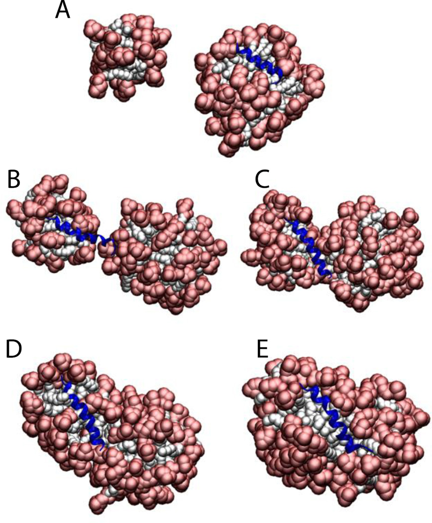
To test whether the presence of the protein affects the aggregation number, Magainin 2 and the ARP1 peptide were placed in a sphere with 100 detergent molecules (100 mM final concentration). The results show that the number of molecules that form a micelle is very close to the aggregation number, but if two micelles get very close to each other they merge into a large elongated micelle. For ARP1 the micelle was formed with the protein on the surface (69 molecules) while another micelle was formed with the leftover monomers (31 molecules) (Fig. 7A). These two micelles stayed away from each other for the 5 ns duration of the simulation. In the Magainin 2 case the molecules started assembling the micelles around two regions of the protein (nucleation points), making a micelle of 37 and 63 (Fig. 7B). When they got close enough the two micelles started merging (Fig. 7C and 7D), until they merged into one micelle at around 300 ps (Fig. 7E). The same behavior was observed with SDS micelles.
Figure 7.
Cartoon representation of the micelle formation using 100 lipids for A) ARP1, and Magainin 2 at B) 20 ps. C) 100 ps. D) 150 ps. E) 300 ps. Head groups are depicted in red and tails in white.
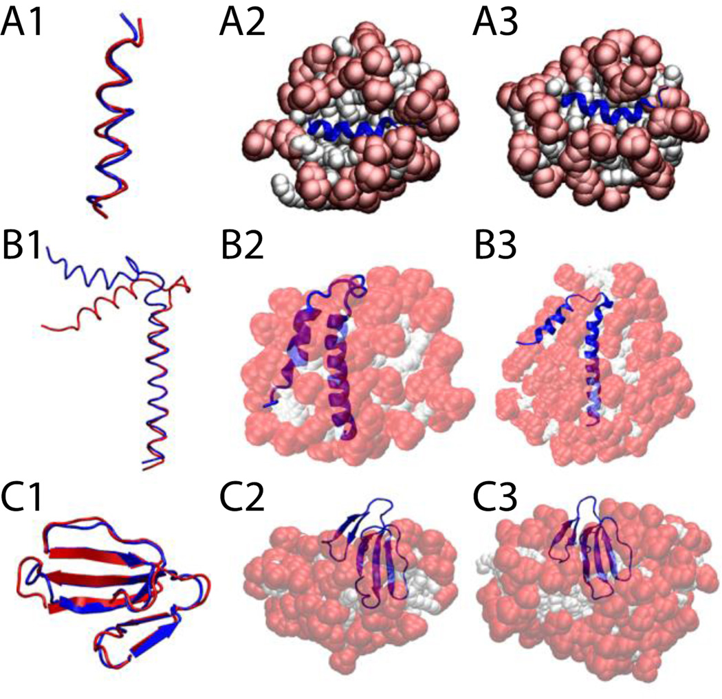
The trp-rich region of the HIV glycoprotein (gp41) was embedded in a 64-molecule DPC micelle, 45 of which remained after the deletion of overlapping molecules (Fig. 8-A2). The protein stayed on the surface in its helical conformation (Fig. 8-A3) with an RMSD value, averaged over three 5-ns runs, of 1.8 ± 0.4 Å with respect to the NMR structure (Fig. 8-A1).
Figure 8.
Cartoon representation of HIV gp41 (A), Phospholamban (B), and P-type cardiotoxin (C) A1, B1, C1, comparison between the experimental structure (blue) versus last frame at 5 ns (red). A2, protein-micelle system after 1 ns with position restraints on the protein. B2, C2, protein-micelle system after 5 ns without restraints with a number of molecules close to the aggregation number. A3, protein-micelle system after 5 ns without restraints. B3, C3, protein-micelle system after 5 ns without restraints with a number of molecules close to twice the aggregation number.
The phospholamban monomer forms two α-helices connected by a flexible turn. A 64-molecule DPC micelle was too small for this protein; the second helix got shorter by one turn while the first one got larger, and the angle between the two helices became ~25°, indicating that the protein adapted its conformation to the size of the micelle (Fig. 8-B2). In a larger system of 131 DPC molecules (Fig. 8-B3), each one of the two α-helices, independently, were conserved with RMSD values less than 1 Å against their respective helix in any of the 20 models of the NMR structure over the entire 5 ns (Fig. 8-B1). Because of the flexible turn, the angle formed by the two helices fluctuates between 35° and 60°, while in the 20 NMR models this angle fluctuates between 45 and 91° (68 ± 23°)62. The angle in Fig. 8-B1 is 68° for the first model of the NMR structure, blue, and 46° for our last frame, red. The micelle assembly and merging is similar to what was described for Magainin 2 in a 100-molecule micelle.
P-type cardiotoxin is a protein with five β-strands and 4 disulfide bonds. Due to the size of the protein two micelle sizes were tested: a 62-molecule (Fig. 8-C2) and a 128-molecule system (Fig. 8-C3). The results were similar; the average RMSD from the NMR structure over the entire 5 ns was 1.8 ± 0.3 Å considering all residues and only 0.9 ± 0.3 Å considering only residues involved in the β-sheets (2–4, 10–13, 19–26, 33–39, 48–54) (Fig. 8-C1). All the deformations are mainly in the loops, which is in agreement with experiment, according to which the β-sheet regions are stable while the loops are flexible63.
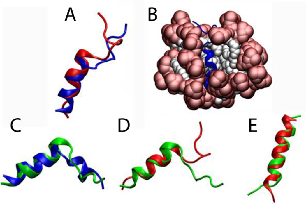
The NMR structure of the 20-residue hemagglutinin fusion peptide at pH 7.4 (pdb id 1IBO) shows a helical conformation from residues 2 to 9 and an extended structure for the C-terminal region with a bend at residues 16 and 1764. In our model (Fig. 9B), residues 1 and 2 are disordered and residues 3 to 10 adopt an α-helix conformation with an average RMSD of 1.0 ± 0.3 Å against its initial structure. This one-residue shift changed the orientation of the extended C-terminus, placing the bend at residues 15, 16 and 17 (instead of only at 16 and 17) (Fig. 9A). To test if our approach can capture pH effects, all the aspartates and glutamates were protonated and the simulation was continued. After 5 ns without constraints it is possible to see that the molecule adopts the same bend angle as the experimental NMR structure at pH 5 (pdb id 1IBN), although it does not form the short 310-helix at the C-terminus (Fig. 9C,D). Starting from the NMR structure at pH 5, for both protonated and non-protonated conditions, the peptide converts to a single, continuous α-helix (Fig. 9E). This may be due to an inability of the force field to capture the correct stability of the 310 helix. The different final structures obtained from different starting structures point to the inability of standard MD to provide a converged conformational distribution in the timescale of a few ns.
Figure 9.
Comparison of A) NMR structure at pH 7.4 (1IBO) (blue) vs. final structure after 5 ns (red). B) protein-micelle system after 5 ns without restraints. C) NMR structure at pH 5 (1IBN) (blue) vs. final structure of protonated 1IBO after 5 ns (green). D) Final structure of 1IBO after 5 ns (red) vs. final structure of protonated 1IBO after 5 ns (green). E) Final structure of unprotonated 1IBN after 5 ns (red) vs. final structure of protonated 1IBN after 5 ns (green).
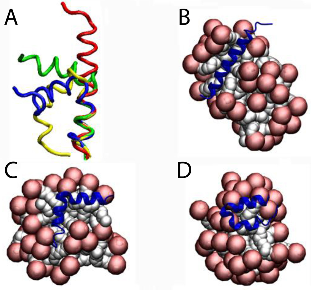
Maximin 4, has a helix-break-helix conformation in a ‘V’ shape with an angle of 70°. This protein was studied in SDS micelles. Similar to phospholamban, after 5 ns of simulation without constraints the helices were conserved but the break is flexible leading to loss of the ‘V’ shape and adoption of an 180° angle (Fig. 10A). That conformation was adopted after 200 ps and stayed the same for the rest of the simulation. To see whether it adopts that conformation randomly or it is energetically preferred, two additional simulations were conducted starting at the end of the restrained simulation (Fig. 10A). The results indicate that the break is flexible and may adopt different orientations, as expected65.Figures 10B,C,D show the last frame of the 5-ns simulation for the three simulations, in all of which the protein is on the surface but the conformation that the protein adopts seems to depend on the topography of the micelle surface.
Figure 10.
Cartoon representation of maximin 4: A) Comparison of the NMR structure (blue) and the last frame of run1 (red), run2 (green), and run3 (yellow) B,C,D) Runs 1,2,3: protein-micelle system after 5 ns without restraints.
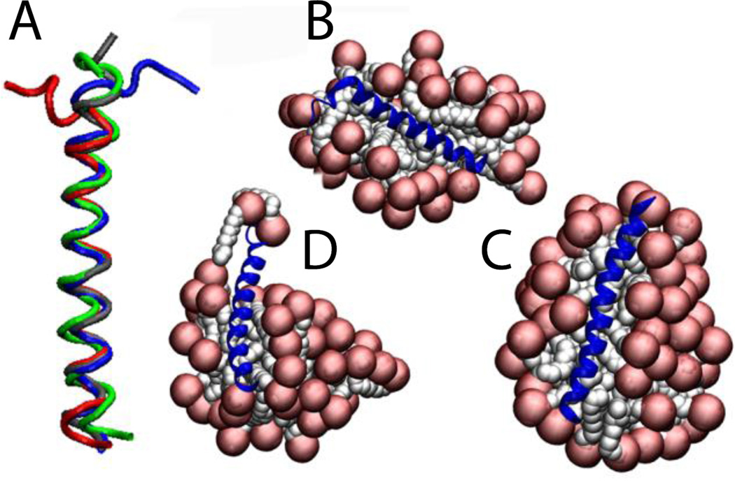
The N-terminal helix of the Bar domain was inserted in a 48-molecule micelle at 150 mM. After 5 ns without constraints the helix is conserved but the N-terminal adopts the shape of the micelle, having the first 7 residues outside the micelle, losing their helical structure (Fig. 11B). A second run shows that two free SDS molecules stabilize these 7 residues (Fig. 11C). If the protein adopts the shape of the micelle, a larger micelle would stabilize the whole protein. For that reason a third run was performed using a 71-molecule micelle at the same concentration, supporting our previous hypothesis (Fig. 11D). The average RMSD value over the entire 5 ns against the NMR structure is 1.5 ± 0.3 Å considering only residues 8 to 32 for run1 and run2, and 1.1 ± 0.2 Å for run3 (Fig. 11A). Löw et al. performed explicit simulations of this peptide on preformed micelles of 40 and 75 molecules and also found that the protein adopts the shape of the micelle surface66.
Figure 11.
Cartoon representation of the N-Bar helix 0 in SDS micelles: A) comparison between the NMR structure (blue) and the last frame at 5 ns of run1 (red), run2 (green) and run3 (gray). B, C,D) Runs 1, 2, 3 of protein-micelle system after 5 ns without restraints.
Protein-micelle systems
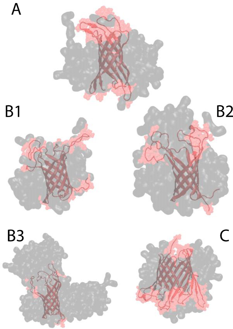
Finally, three larger β-barrel proteins were tested: OMPX, OMPA and OMPG. For all of them the β-barrel was conserved while the loops were very flexible. Due to this flexibility the RMSD value for the whole protein backbone against its respective NMR structure was close to 5 Å, while the backbone RMSD of the β-barrel residues only is approximately 1.9 Å for all three proteins67,68. OMPX was placed in a 70-molecule system. After 5 ns the position of the lipids with respect to the protein was consistent with experimental NOE data for OMPX in DHPC micelles11, according to which the lipids interact with hydrophobic residues in the β-barrel region (Fig. 12-A). In the OMPX molecule the β-barrel is hydrophobic and the loops are hydrophilic, while OMPA and OMPG have several hydrophobic residues also in the loops. In the case of OMPA, three micelle sizes were tested: 67, 109 and 203. In all three cases the backbone of only the β-barrel residues has an RMSD less than 1.9 Å, while the RMSD of the entire backbone is 7.0, 4.5, 4.0 for the 67-, 109-, 203- molecule system, respectively. This indicates that the 67-molecule micelle is not sufficient to stabilize the hydrophobic residues in the loops (Fig. 12 - B1, B2 and B3). The growth of the micelles was similar to what was described before with several micelles starting to merge when they get close enough, and in the 203-molecule system the detergent molecules form a structure similar to a worm-like micelle8 (Fig. 12-B3). OMPG was placed in an 80- (Fig. 12-C) and 208-molecule system. In both cases the RMSD of the β-barrel residues was 2 Å and the RMSD of the whole backbone was 5 Å.
Figure 12.
Cartoon representation of (A) OMPX in a DPC micelle, (B1) OMPA 67-molecule DPC system, (B2) OMPA 109-molecule DPC system, (B3) OMPA 230-molecule DPC system, and (C) OMPG in a DPC 80-molecule DPC system. Gray and pink shades correspond to surface representation of the micelle and the protein, respectively.
DISCUSSION
The implicit water models for DPC and SDS reported here give aggregation numbers and CMC values that are close to the experimental values. Modeling peptides and proteins in these micelles gives secondary and tertiary structures consistent with the NMR structures, with deformations observed in the termini and/or the flexible turns or loops. In addition, detergent-protein interactions were consistent with experimental data, wherever those were available. In the vast majority of cases where such information is not available experimentally, the models could provide a detailed molecular description of the placement and the interaction of the protein with the lipids. Removing the solvent molecules reduces dramatically the computational requirements. One advantage compared to coarse-grain models is the atomistic representation of the protein and the lipid, which makes such studies more physically realistic. Another advantage is that the protein structure is allowed to adapt, in contrast to many coarse-grained simulations where it is constrained69.
The ratio between aggregation numbers Nw and Nn is an indicator of polydispersity7,45. Many experimental results suggest that this ratio is close to 1.0 for SDS at low salt concentration70–73. At high salt concentration, polydispersity was observed59 and also a transition of the micelle shape from sphere to rod57,72. In the present model the Nw/Nn ratio for DPC is 1.3. For SDS it is 2.6 at 50 mM and 1.6 at 200 and 400 mM. Our SDS model corresponds to zero salt concentration, but for some reason the degree of polydispersity is higher than what experiment suggests. This could possibly be attributed to the following factors: 1) lack of convergence; slow micelle diffusion and merging processes could bring about a more uniform distribution. 2) The relatively small system size (960 or 1000 molecules). 3) The possible inability of additive potentials to capture the cooperativity of hydrophobic interactions.
For the purposes of this work it would have been useful to use a united atom force field, i.e. one that models implicitly the nonpolar hydrogens. Lee et al. proposed a united atom CHARMM36 force field74 that successfully reproduced the Nw aggregation number in explicit solvent simulations. Using that force field with the same solvation parameters used here for all-atom DPC, we obtained a number of free monomers (Nmon), and thus a CMC, close to zero. This difference can be traced to the van der Waals interactions between the tails: the difference in van der Waals energy between a free SDS monomer and a SDS monomer in a micelle is −8.7 kJ/mol for the all-atom force field and −10.6 kJ/mol for the united atom force field. To compensate for this additional attraction, one would have to adjust the EEF1 solvation parameters.
Experimentally it is difficult to determine the radius of a micelle because the experimental values usually include the hydration shell and this is also affected by the presence of ions. The average radius of gyration for the DPC micelle that we obtained is in agreement with our previous work33 and also other authors24. The average radius of gyration for the SDS micelle is also in agreement with other authors’ values such as 16.0 Å16 and close to the 15.4 Å obtained for lithium dodecyl sulfate71 and 15 Å by Shelley et al.17.
Micelles are commonly visualized as spherical but there is not much experimental information on their actual shape. MacKerell reported SDS micelles close to spherical16 but other authors, also using MD simulations, reported a prolate ellipsoid shape17. Here, for both DPC and SDS the ratio of moments of inertia indicates that the micelles deviate significantly from spherical shape. The micelles have different principal moments of inertia (I1 > I2 > I3), adopting oblate ellipsoid and more complex shapes. Several authors also obtained DPC micelles that deviated from spherical shape23,24,74. Benedek’s group performed a series of experiments on SDS micelles to see the sphere to rod transition as a function of concentration, temperature and ionic strength by light scattering techniques75, suggesting that the shape of the micelle is sensitive to environmental changes. An interesting direction for future work would be to incorporate the effect of ionic strength into the implicit water model to study the sphere to rod transition.
The present simulations were done at concentrations much higher than the CMC. Aggregation numbers seem to be concentration dependent, i.e. for a 30 mM SDS system the Nagg is between 48 to 59, at 40 mM is 61 to 64, at 50 mM is 62 to 65, and at 100 mM is 65 to 7376. Storm et al. suggest the possibility that large systems could evolve toward the formation of bigger aggregates77. Aggregation numbers are also salt concentration dependent58,78. These dependencies open the possibility that aggregation numbers might also depend on the presence of an external particle, such as a protein. This issue is not well characterized experimentally and could be investigated more systematically using the present modeling approach (Fig. 7).
The N-terminal Bar domain and Phospholamban simulations showed different conformations depending on the size of the micelle. Other groups also showed that the curvature of the helix and the helicity depends on the micelle shape and SDS concentration66. Studies on α-synuclein revealed that the structure depends on the shape or curvature of the bicelle, micelle, vesicle and bilayer2 and that the protein/lipid ratio determines the conformation that the protein will adopt79. These issues could also be fruitfully investigated using the present approach.
The implicit treatment of water allows the study of large protein systems with modest computational resources. It may be possible, for example, to obtain an atomistic view of an SDS-denatured protein and explore the role of surfactants in membrane protein crystallization. It is possible now to extend this study to other commonly used surfactants such as octyl glucoside, dodecyl maltoside, CTAB and CHAPS. Comparison of different surfactants might allow one to address the question why some detergents are denaturing and others are not. Another future direction may be the extension of this approach to study the self-assembly of lipids to form bilayers, such as DMPC or POPC. Comparative studies against micelles will offer insights on how well micelles mimic biological membranes.
Supplementary Material
Acknowledgments
Funding for this research was provided by the National Science Foundation (MCB 1244207). Infrastructure support was provided in part by RCMI grant 8G12MD007603-29 from the National Institutes of Health.
Footnotes
SUPPORTING INFORMATION AVAILABLE
Three figures and one table of RMSD vs. time for peptides in DPC and SDS micelles. This information is available free of charge via the Internet at http://pubs.acs.org.
REFERENCES
- 1.Ostermeier C, Hartmut M. Crystallization of Membrane Proteins. Curr. Opin. Struct. Biol. 1997;7:697–701. doi: 10.1016/s0959-440x(97)80080-2. [DOI] [PubMed] [Google Scholar]
- 2.Warschawski DE, Arnold Aa, Beaugrand M, Gravel A, Chartrand É, Marcotte I. Choosing Membrane Mimetics for NMR Structural Studies of Transmembrane Proteins. Biochim. Biophys. Acta. 2011;1808:1957–1974. doi: 10.1016/j.bbamem.2011.03.016. [DOI] [PubMed] [Google Scholar]
- 3.Hagn F, Etzkorn M, Raschle T, Wagner G. Optimized Phospholipid Bilayer Nanodiscs Facilitate High-Resolution Structure Determination of Membrane Proteins. J. Am. Chem. Soc. 2013;135:1919–1925. doi: 10.1021/ja310901f. [DOI] [PMC free article] [PubMed] [Google Scholar]
- 4.Fernández C, Wüthrich K. NMR Solution Structure Determination of Membrane Proteins Reconstituted in Detergent Micelles. FEBS Lett. 2003;555:144–150. doi: 10.1016/s0014-5793(03)01155-4. [DOI] [PubMed] [Google Scholar]
- 5.Tanford C. The Hydrophobic Effect and the Organization of Living Matter. Science (80-.) 1978;200:1012–1018. doi: 10.1126/science.653353. [DOI] [PubMed] [Google Scholar]
- 6.Ezrahi S, Tuval E, Aserin A. Properties, Main Applications and Perspectives of Worm Micelles. Adv. Colloid Interface Sci. 2006;128–130:77–102. doi: 10.1016/j.cis.2006.11.017. [DOI] [PubMed] [Google Scholar]
- 7.Mukerjee P. The Size Distribution of Small and Large Micelles?: A Multiple Equilibrium Analysis. J. Phys. Chem. 1972;76:565–570. [Google Scholar]
- 8.Michels B, Waton G. Kinetics Associated with the Length Change of Micelles in SDS Solutions. J. Phys. Chem. B. 2000;104:228–232. [Google Scholar]
- 9.Sharma VK, Mitra S, Verma G, Hassan Pa, Garcia Sakai V, Mukhopadhyay R. Internal Dynamics in SDS Micelles: Neutron Scattering Study. J. Phys. Chem. B. 2010;114:17049–17056. doi: 10.1021/jp108274y. [DOI] [PubMed] [Google Scholar]
- 10.Lang J. Surfactant Aggregation Number and Polydispersity of SDS 4-1-Pentanol Mixed Micelles in Brine Determined by Time-Resolved Fluorescence Quenching. J. Phys. Chem. 1990;94:3734–3739. [Google Scholar]
- 11.Fernández C, Hilty C, Wider G, Wüthrich K. Lipid-Protein Interactions in DHPC Micelles Containing the Integral Membrane Protein OmpX Investigated by NMR Spectroscopy. Proc. Natl. Acad. Sci. U.S.A. 2002;99:13533–13537. doi: 10.1073/pnas.212515099. [DOI] [PMC free article] [PubMed] [Google Scholar]
- 12.Hilty C, Wider G, Fernández C, Wüthrich K. Membrane Protein-Lipid Interactions in Mixed Micelles Studied by NMR Spectroscopy with the Use of Paramagnetic Reagents. Chembiochem. 2004;5:467–473. doi: 10.1002/cbic.200300815. [DOI] [PubMed] [Google Scholar]
- 13.Jönsson B, Edholm O, Teleman O. Molecular Dynamics Simulations of a Sodium Octanoate Micelle in Aqueous Solution. J. Chem. Phys. 1986;85:2259–2271. [Google Scholar]
- 14.Watanabe K, Ferrario M, Klein ML. Molecular Dynamics Study of a Sodium Octanoate Micelle in Aqueous Solution. J. Phys. Chem. 1988;92:819–821. [Google Scholar]
- 15.Bogusz S, Venable RM, Pastor RW. Molecular Dynamics Simulations of Octyl Glucoside Micelles?: Structural Properties. J. Phys. Chem. B. 2000;104:5462–5470. [Google Scholar]
- 16.Mackerell A. Molecular Dynamics Simulation Analysis of a Sodium Dodecyl Sulfate Micelle in Aqueous Solution?: Decreased Fluidity of the Micelle Hydrocarbon Interior. J. Phys. Chem. 1995;99:1846–1855. [Google Scholar]
- 17.Shelley J, Watanabe K, Klein ML. Simulation of a Sodium Dodecylsulfate Micelle in Aqueous Solution. Int. J. Quantum Chem.,Quantum Bid. Symp. 1990;38:103–117. [Google Scholar]
- 18.Bruce CD, Berkowitz ML, Perera L, Forbes MDE. Molecular Dynamics Simulation of Sodium Dodecyl Sulfate Micelle in Water: Micellar Structural Characteristics and Counterion Distribution. J. Phys. Chem. B. 2002;106:3788–3793. [Google Scholar]
- 19.Rakitin AR, Pack GR. Molecular Dynamics Simulations of Ionic Interactions with Dodecyl Sulfate Micelles. J. Phys. Chem. B. 2004;108:2712–2716. [Google Scholar]
- 20.Sammalkorpi M, Karttunen M, Haataja M. Ionic Surfactant Aggregates in Saline Solutions: Sodium Dodecyl Sulfate (SDS) in the Presence of Excess Sodium Chloride (NaCl) or Calcium Chloride (CaCl 2) J. Phys. Chem. B. 2009;113:5863–5870. doi: 10.1021/jp901228v. [DOI] [PubMed] [Google Scholar]
- 21.Tang X, Koenig PH, Larson RG. Molecular Dynamics Simulations of Sodium Dodecyl Sulfate Micelles in Water-the Effect of the Force Field. J. Phys. Chem. B. 2014;118:3864–3880. doi: 10.1021/jp410689m. [DOI] [PubMed] [Google Scholar]
- 22.Marrink SJ, Tieleman DP, Mark AE. Molecular Dynamics Simulation of the Kinetics of Spontaneous Micelle Formation. J. Phys. Chem. B. 2000;104:12165–12173. [Google Scholar]
- 23.Tieleman DP, Spoel D. Van Der, Berendsen HJC, April RV. Molecular Dynamics Simulations of Dodecylphosphocholine Micelles at Three Different Aggregate Sizes?: Micellar Structure and Chain Relaxation. 2000;23:6380–6388. [Google Scholar]
- 24.Wymore T, Gao XF, Wong TC. Molecular Dynamics Simulation of the Structure and Dynamics of a Dodecylphosphocholine Micelle in Aqueous Solution. J. Mol. Struct. 1999;485–486:195–210. [Google Scholar]
- 25.Abel S, Dupradeau FY, Marchi M. Molecular Dynamics Simulations of a Characteristic DPC Micelle in Water. J. Chem. Theory Comput. 2012;8:4610–4623. doi: 10.1021/ct3003207. [DOI] [PubMed] [Google Scholar]
- 26.Khandelia H, Kaznessis YN. Molecular Dynamics Simulations of the Helical Antimicrobial Peptide Ovispirin-1 in a Zwitterionic Dodecylphosphocholine Micelle: Insights into Host-Cell Toxicity. J. Phys. Chem. B. 2005;109:12990–12996. doi: 10.1021/jp050162n. [DOI] [PubMed] [Google Scholar]
- 27.Dixon AM, Venable RM, Pastor RW, Bull TE. Micelle-Bound Conformation of a Hairpin-Forming Peptide: Combined NMR and Molecular Dynamics Study. Biopolymers. 2002;65:284–298. doi: 10.1002/bip.10249. [DOI] [PubMed] [Google Scholar]
- 28.Braun R, Engelman DM, Schulten K. Molecular Dynamics Simulations of Micelle Formation around Dimeric Glycophorin A Transmembrane Helices. Biophys. J. 2004;87:754–763. doi: 10.1529/biophysj.104.040279. [DOI] [PMC free article] [PubMed] [Google Scholar]
- 29.Marrink SJ, Vries A. H. De, Mark AE. Coarse Grained Model for Semiquantitative Lipid Simulations. J. Phys. Chem. B. 2004;108:750–760. [Google Scholar]
- 30.Sanders Sa, Panagiotopoulos AZ. Micellization Behavior of Coarse Grained Surfactant Models. J. Chem. Phys. 2010;132:114902. doi: 10.1063/1.3358354. [DOI] [PubMed] [Google Scholar]
- 31.Shelley JC, Shelley MY. Computer Simulation of Surfactant Solutions. Curr. Opin. Colloid Interface Sci. 2000;5:101–110. [Google Scholar]
- 32.Lazaridis T, Versace R. The Treatment of Solvent in Multiscale Biophysical Modeling. Isr. J. Chem. 2014:1074–1083. [Google Scholar]
- 33.Lazaridis T, Mallik B, Chen Y. Implicit Solvent Simulations of DPC Micelle Formation. J. Phys. Chem. B. 2005;109:15098–15106. doi: 10.1021/jp0516801. [DOI] [PubMed] [Google Scholar]
- 34.Lazaridis T, Karplus M. Effective Energy Function for Proteins in Solution. Proteins. 1999;35:133–152. doi: 10.1002/(sici)1097-0134(19990501)35:2<133::aid-prot1>3.0.co;2-n. [DOI] [PubMed] [Google Scholar]
- 35.Shinto H, Morisada S, Miyahara M, Higashitani K. Langevin Dynamics Simulations of Cationic Surfactants in Aqueous Solutions Using Potentials of Mean Force. Langmuir. 2004;20:2017–2025. [Google Scholar]
- 36.Jusufi A, Hynninen A-P, Panagiotopoulos AZ. Implicit Solvent Models for Micellization of Ionic Surfactants. J. Phys. Chem. B. 2008;112:13783–13792. doi: 10.1021/jp8043225. [DOI] [PubMed] [Google Scholar]
- 37.Wang Y, Wallace Ja, Koenig PH, Shen JK. Molecular Dynamics Simulations of Ionic and Nonionic Surfactant Micelles with a Generalized Born Implicit-Solvent Model. J. Comput. Chem. 2011;32:2348–2358. doi: 10.1002/jcc.21813. [DOI] [PubMed] [Google Scholar]
- 38.Brooks BR, Brooks CL, Mackerell AD, Nilsson L, Petrella RJ, Roux B, Won Y, Archontis G, Bartels C, Boresch S, et al. CHARMM: The Biomolecular Simulation Program. J. Comput. Chem. 2009;30:1545–1614. doi: 10.1002/jcc.21287. [DOI] [PMC free article] [PubMed] [Google Scholar]
- 39.Klauda JB, Venable RM, Freites JA, O’Connor JW, Tobias DJ, Mondragon-Ramirez C, Vorobyov I, MacKerell AD, Pastor RW. Update of the CHARMM All-Atom Additive Force Field for Lipids: Validation on Six Lipid Types. J. Phys. Chem. B. 2010;114:7830–7843. doi: 10.1021/jp101759q. [DOI] [PMC free article] [PubMed] [Google Scholar]
- 40.Mackerell AD, Feig M, Brooks CL. Extending the Treatment of Backbone Energetics in Protein Force Fields: Limitations of Gas-Phase Quantum Mechanics in Reproducing Protein Conformational Distributions in Molecular Dynamics Simulation. J. Comput. Chem. 2004;25:1400–1415. doi: 10.1002/jcc.20065. [DOI] [PubMed] [Google Scholar]
- 41.Torrie GM, Valleau JP. Nonphysical Sampling Distributions in Monte Carlo Free-Energy Estimation: Umbrella Sampling. J. Comput. Phys. 1977;23:187–199. [Google Scholar]
- 42.Beglov D, Roux B, Hc C. Finite Representation of an Infinite for Computer Simulations Bulk System?: Solvent Boundary Potential. J. Med. Phys. 1994;100:9050–9063. [Google Scholar]
- 43.Kumar S, Rosenberg JM, Bouzida D, Swendsen RH, Kollman PA. The Weighted Histogram Analysis Method for Free-energy Calculations on Biomolecules. I. The Method. J. Comput. Chem. J. Comput. Chem. 1992;13:1011–1021. [Google Scholar]
- 44.Grossfield A. WHAM: The Weighted Histogram Analysis Method. http://membrane.urmc.rochester.edu/content/wham.
- 45.Nagarajan R. On Interpreting Fluorescense Measurements: What Does Thermodynamics Have to Say about Changes in Micellar Aggregation Number versus Change in Size Distribution by Increasing Concentration of the Surfactant in Solution? Langmuir. 1994;10:2028–2034. [Google Scholar]
- 46.Tanford C. The Hydrophobic Effect: Formation of Micelles and Biological Membranes. 2nd. Wiley-Interscience: New York; 1980. [Google Scholar]
- 47.Humphrey W, Dalke A, Schulten K. VMD: Visual Molecular Dynamics. J. Mol. Graph. 1996;14:33–38. doi: 10.1016/0263-7855(96)00018-5. [DOI] [PubMed] [Google Scholar]
- 48.Feller SE, Mackerell ADJ. An Improved Empirical Potential Energy Function for Molecular Simulations of Phospholipids. J. Phys. Chem. B. 2000;104:7510–7515. [Google Scholar]
- 49.Sanders Sa, Sammalkorpi M, Panagiotopoulos AZ. Atomistic Simulations of Micellization of Sodium Hexyl, Heptyl, Octyl, and Nonyl Sulfates. J. Phys. Chem. B. 2012;116:2430–2437. doi: 10.1021/jp209207p. [DOI] [PubMed] [Google Scholar]
- 50.Sammalkorpi M, Karttunen M, Haataja M. Structural Properties of Ionic Detergent Aggregates: A Large-Scale Molecular Dynamics Study of Sodium Dodecyl Sulfate. J. Phys. Chem. B. 2007;111:11722–11733. doi: 10.1021/jp072587a. [DOI] [PubMed] [Google Scholar]
- 51.Bastiat G, Grassl B, Khoukh A, Francois J. Study of Sodium Dodecyl Sulfate - Poly ( Propylene Oxide ) Methacrylate Mixed Micelles. Langmuir. 2004;20:5759–5769. doi: 10.1021/la049890c. [DOI] [PubMed] [Google Scholar]
- 52.Vautier-Giongo C, Bales BL. Estimate of the Ionization Degree of Ionic Micelles Based on Krafft Temperature Measurements. J. Phys. Chem. B. 2003;107:5398–5403. [Google Scholar]
- 53.Bales BLA. Definition of the Degree of Ionization of a Micelle Based on Its Aggregation Number. J. Phys. Chem. B. 2001;105:6798–6804. [Google Scholar]
- 54.Stigter D, Mysels KJ. Tracer Electrophoresis. II. The Mobility of the Micelle of Sodium Lauryl Sulfate and Its Interpretation in Terms of Zeta Potential and Charge. J. Phys. Chem. 1955;59:45–51. [Google Scholar]
- 55.Benrraou M, Bales BL, Zana R. Effect of the Nature of the Counterion on the Properties of Anionic Surfactants. 1. Cmc, Ionization Degree at the Cmc and Aggregation Number of Micelles of Sodium, Cesium, Tetramethylammonium, Tetraethylammonium, Tetrapropylammonium, and Tetrabutylammoniu. J. Phys. Chem. B. 2003;107:13432–13440. [Google Scholar]
- 56.Quina FH, Nassar P, Bonilha J, Bales BL. Growth of Sodium Dodecyl Sulfate Micelles with Detergent Concentration. J. Phys. Chem. 1995;99:17028–17031. [Google Scholar]
- 57.Zhao Jing, Fung BM. NMR Study of the Transformation of Sodium Dodecyl Sulfate Micelles. Langmuir. 1993;9:1228–1231. [Google Scholar]
- 58.Croonen Y, Gelade E, Van der Zegel M, Van der Auweraer M, Vandendriessche H, De Schryver F, Almgrent M. Influence of Salt, Detergent Concentration, and Temperature on the Fluorescence Quenching of 1-Methylpyrene in Sodium Dodecyl Sulfate with M-Dicyanobenzene. J. Phys. Chem. 1983;87:1426–1431. [Google Scholar]
- 59.Bales BL, Almgren M. Fluorescence Quenching of Pyrene by CoppeRI1) in Sodium Dodecyl Sulfate Micelles. Effect of Micelle Size As Controlled by Surfactant Concentration. J. Phys. Chem. 1995;99:15153–15162. [Google Scholar]
- 60.Gesell J, Zasloff M, Opella SJ. Two-Dimensional 1H NMR Experiments Show That the 23-Residue Magainin Antibiotic Peptide Is an Alpha-Helix in Dodecylphosphocholine Micelles, Sodium Dodecylsulfate Micelles, and Trifluoroethanol/water Solution. J. Biomol. NMR. 1997;9:127–135. doi: 10.1023/a:1018698002314. [DOI] [PubMed] [Google Scholar]
- 61.Bourbigot S, Dodd E, Horwood C, Cumby N, Fardy L, Welch WH, Ramjan Z, Sharma S, Waring AJ, Yeaman MR, et al. Antimicrobial Peptide RP-1 Structure and Interactions with Anionic versus Zwitterionic Micelles. Biopolymers. 2009;91:1–13. doi: 10.1002/bip.21071. [DOI] [PubMed] [Google Scholar]
- 62.Zamoon J, Mascioni A, Thomas DD, Veglia G. NMR Solution Structure and Topological Orientation of Monomeric Phospholamban in Dodecylphosphocholine Micelles. Biophys. J. 2003;85:2589–2598. doi: 10.1016/s0006-3495(03)74681-5. [DOI] [PMC free article] [PubMed] [Google Scholar]
- 63.Dubovskii PV, Dementieva DV, Bocharov EV, Utkin YN, Arseniev aS. Membrane Binding Motif of the P-Type Cardiotoxin. J. Mol. Biol. 2001;305:137–149. doi: 10.1006/jmbi.2000.4283. [DOI] [PubMed] [Google Scholar]
- 64.Han X, Bushweller JH, Cafiso DS, Tamm LK. Membrane Structure and Fusion-Triggering Conformational Change of the Fusion Domain from Influenza Hemagglutinin. Nat. Struct. Biol. 2001;8:715–720. doi: 10.1038/90434. [DOI] [PubMed] [Google Scholar]
- 65.Toke O, Bánóczi Z, Király P, Heinzmann R, Bürck J, Ulrich AS, Hudecz F. A Kinked Antimicrobial Peptide from Bombina Maxima. I. Three-Dimensional Structure Determined by NMR in Membrane-Mimicking Environments. Eur. Biophys. J. 2011;40:447–462. doi: 10.1007/s00249-010-0657-0. [DOI] [PubMed] [Google Scholar]
- 66.Löw C, Weininger U, Lee H, Schweimer K, Neundorf I, Beck-Sickinger AG, Pastor RW, Balbach J. Structure and Dynamics of Helix-0 of the N-BAR Domain in Lipid Micelles and Bilayers. Biophys. J. 2008;95:4315–4323. doi: 10.1529/biophysj.108.134155. [DOI] [PMC free article] [PubMed] [Google Scholar]
- 67.Arora A, Abildgaard F, Bushweller JH, Tamm LK. Structure of Outer Membrane Protein A Transmembrane Domain by NMR Spectroscopy. Nat. Struct. Biol. 2001;8:334–338. doi: 10.1038/86214. [DOI] [PubMed] [Google Scholar]
- 68.Liang B, Tamm LK. Structure of Outer Membrane Protein G by Solution NMR Spectroscopy. Proc. Natl. Acad. Sci. U.S.A. 2007;104:16140–16145. doi: 10.1073/pnas.0705466104. [DOI] [PMC free article] [PubMed] [Google Scholar]
- 69.Monticelli L, Kandasamy SK, Periole X, Larson RG, Tieleman DP, Marrink SJ. The MARTINI Coarse-Grained Force Field: Extension to Proteins. J. Chem. Theory Comput. 2008;4:819–834. doi: 10.1021/ct700324x. [DOI] [PubMed] [Google Scholar]
- 70.Turro NJ, Yekta A. Luminescent Probes for Detergent Solutions. A Simple Procedure for Determination of the Mean Aggregation Number of Micelles. JACS. 1978;100:5951–5952. [Google Scholar]
- 71.Bendedouch D, Chen S. Structure of Ionic Micelles from Small Angle Neutron Scattering. J. Phys. Chem. 1983;87:153–159. [Google Scholar]
- 72.Siemiarczuk A, Ware WR, Liu YS. A Novel Method for Determining Size Distributions in Polydisperse Micelle Systems Based on the Recovery of Fluorescence Lifetime Distributions. J. Phys. Chem. 1993;97:8082–8091. [Google Scholar]
- 73.Hall DG. Polydispersity of Sodium Dodecyl Sulfate (SDS) Micelles. Langmuir. 1999;15:3483–3485. [Google Scholar]
- 74.Lee S, Tran A, Allsopp M, Lim JB, Hénin J, Klauda JB. CHARMM36 United Atom Chain Model for Lipids and Surfactants. J. Phys. Chem. B. 2014;118:547–556. doi: 10.1021/jp410344g. [DOI] [PubMed] [Google Scholar]
- 75.Missel PJ, Mazer NA, Benedek GB, Young CY, Carey MC. Thermodynamic Analysis of the Growth of Sodium Dodecyl Sulfate Micelles. J. Phys. Chem. 1980;84:1044–1057. [Google Scholar]
- 76.Anachkov SE, Danov KD, Basheva ES, Kralchevsky Pa, Ananthapadmanabhan KP. Determination of the Aggregation Number and Charge of Ionic Surfactant Micelles from the Stepwise Thinning of Foam Films. Adv. Colloid Interface Sci. 2012;183–184:55–67. doi: 10.1016/j.cis.2012.08.003. [DOI] [PubMed] [Google Scholar]
- 77.Storm S, Jakobtorweihen S, Smirnova I, Panagiotopoulos AZ. Molecular Dynamics Simulation of SDS and CTAB Micellization and Prediction of Partition Equilibria with COSMOmic. Langmuir. 2013;29:11582–11592. doi: 10.1021/la402415b. [DOI] [PubMed] [Google Scholar]
- 78.Gangabadage CS, Najda A, Bogdan D, Wijmenga SS, Tessari M. Dependence of the Size of a Protein-SDS Complex on Detergent and Na+ Concentrations. J. Phys. Chem. B. 2008;112:4242–4245. doi: 10.1021/jp710045e. [DOI] [PubMed] [Google Scholar]
- 79.Georgieva ER, Ramlall TF, Borbat PP, Freed JH, Eliezer D. The Lipid-Binding Domain of Wild Type and Mutant α-Synuclein: Compactness and Interconversion between the Broken and Extended Helix Forms. J. Biol. Chem. 2010;285:28261–28274. doi: 10.1074/jbc.M110.157214. [DOI] [PMC free article] [PubMed] [Google Scholar]
Associated Data
This section collects any data citations, data availability statements, or supplementary materials included in this article.


