

Abstract
To test the “traction fiber” model for metaphase positioning of bivalents during meiosis, kinetochore fibers of maloriented bivalents, induced during recovery from cold arrest, were analyzed with a liquid crystal polarizing microscope. The measured birefringence retardation of kinetochore fibers is proportional to the number of microtubules in a fiber. Five of the 11 maloriented bivalents analyzed exhibited bipolar malorientations that had at least four times more kinetochore microtubules to one pole than to the other pole, and two had microtubules directed to only one pole. Yet all maloriented bivalents had positions at or near the spindle equator. The traction fiber model predicts such maloriented bivalents should be positioned closer to the pole with more kinetochore microtubules. A metaphase position at the spindle equator, according to the model, requires equal numbers of kinetochore microtubules to both poles. Data from polarizing microscope images were not in accord with those predictions, leading to the conclusion that other factors, in addition to traction forces, must be involved in metaphase positioning in crane-fly spermatocytes. Although the identity of additional factors has not been established, one possibility is that polar ejection forces operate to exert away-from-the-pole forces that could counteract pole-directed traction forces. Another is that kinetochores are “smart,” meaning they embody a position-sensitive mechanism that controls their activity.
INTRODUCTION
We report findings concerning the question: What is the nature of the mechanism underlying the positioning of bivalent chromosomes at the metaphase plate? The long-standing “traction fiber” model (Pickett-Heaps et al., 1996, for review) was tested in living spermatocytes from crane flies. That model explains the positioning of nonoscillating bivalent chromosomes in terms of tensile forces generated by spindle matrix-associated motors that act along the whole kinetochore fiber. It stands in contrast to the kinetochore motor/polar ejection force model (Rieder and Salmon, 1994), which proposes kinetochores to be the sites of poleward force production and explains the oscillatory behavior characteristic of metaphase mitotic chromosomes as an interplay between kinetochore-dependent poleward forces and kinetochore-independent polar ejection forces (see Khodjakov et al., 1999 for review).
A key feature of the traction fiber model is its force-distance relationship (Östergren, 1950, 1951), which specifies that the magnitude of the force exerted by a traction fiber is directly proportional to its length (Hays et al., 1982). Thus, at metaphase of meiosis, a bivalent has a position at the spindle equator because the length of the traction fiber (and the poleward force exerted by it) to one pole equals that of the fiber to the other pole.
Recently, the model has been further articulated by Hays and Salmon (1990) to specify that poleward force exerted by a traction fiber depends on both the lengths and number of kinetochore microtubules included within it. In that often cited laser microbeam study using grasshopper spermatocytes, ablation of one of the four kinetochores of a bivalent caused it to shift to a new stable position off the equator, closer to one pole toward which its unirradiated kinetochores faced. Thin-section electron microscopy (EM) revealed kinetochore microtubules on the irradiated side of a bivalent were reduced in number, whereas the number of kinetochore microtubules on the unirradiated side was similar to that in controls. Both of those results are consistent with the traction fiber model. In the Hays and Salmon (1990) version of the model, metaphase force equilibrium is achieved by traction fibers because the total kinetochore microtubule polymer (length multiplied by number) attaching a bivalent to one pole equals the total polymer attaching it to the other pole.
In the present work, bivalent malorientations were induced in crane-fly spermatocytes during recovery from meiotic arrest (Janicke and LaFountain, 1982, 1984, 1986) and analyzed with a liquid crystal polarizing microscope (Oldenbourg and Mei, 1995). The latter was used to both quantify the microtubule content of kinetochore fibers and maintain a temporal record of bivalents and their kinetochore fibers during the course of division.
Our findings are not in agreement with the traction fiber model that emerged from the earlier work on grasshoppers. We found maloriented bivalents stable at the spindle equator, even when there was a gross imbalance in the number of kinetochore microtubules attaching a bivalent to the two spindle poles. The data indicate the metaphase positioning of bivalents in crane-fly spermatocytes cannot be explained solely in terms of pole-directed force producers acting along the length of kinetochore microtubules. We conclude, therefore, that the mechanism of bivalent positioning is more complex than the current traction fiber model suggests and likely involves other factors, such as polar ejection forces and/or “smart” kinetochores, the latter proposed by Mitchison (1989) to explain chromosome positioning using a position-sensitive mechanism to control kinetochore activity.
MATERIALS AND METHODS
Spermatocyte Culture
Larvae in the fourth instar were selected from a laboratory colony. Testes were isolated in tricine insect buffer (Begg and Ellis, 1979) and submerged under a droplet of Voltalef 10s oil (Ugine Kuhlmann, Paris, France) on a coverslip, where spermatocytes released upon rupturing of the testicular sheath were smeared as a monolayer at the oil-coverslip interface. A ring of Vaseline placed around the oil droplet and four drops of VALAP (a molten mixture of one part each of Vaseline, lanolin, and paraffin) placed at the corners of the coverslip served as spacers upon mounting the coverslip on a glass microscope slide. Spermatocytes survived in such oil preparations for a few hours, sufficient for observation of both meiotic divisions in an individual living spermatocyte.
Cold Treatments That Induced Chromosome Malorientation
For cold treatments to induce chromosome malorientation, selected larvae were transferred from the moist tissue paper mulch that serves as their culture medium in the lab to fresh mulch contained in a 90 × 50-mm crystallizing dish, which was subsequently put on ice in a refrigerator for the duration of cold exposure, typically 24–36 h. Those conditions maintained the temperature of the mulch, and the larvae, at 0–1°C. For microscopy during cold recovery, larvae were removed from the cold, transferred to fresh mulch at room temperature (∼24°C), and then after ∼10 min of recovery, testes were isolated and oil preps were made as with control, untreated material. Typically, 20–30 min of recovery time were spent on specimen preparation before cold-recovering cells were actually located and imaged with the polarizing microscope. This sacrifice of recovery time in specimen preparation was necessitated by the room temperature environment of the microscope. As a consequence of using this approach of preparing cells for observation after recovery onset, complete historical records of the induction of malorientation, which were obtained in earlier studies (Janicke and LaFountain, 1986), were not obtained here.
Polarization Microscopy
Images of birefringent spindle fibers were obtained with a polarizing microscope that was equipped with a liquid crystal universal compensator (LC-PolScope, Cambridge Research and Instrumentation, Woburn, MA) and was operated as described by Oldenbourg and Mei (1995) and by Oldenbourg et al. (1998). The optical set-up included a 60×/1.4 NA plan apochromat oil immersion objective and apochromat oil immersion condenser. Images were stored as TIFF files and imported into NIH image for analysis (NIH image is public-domain software for image analysis available online from NIH Image http://rsb.info.nih.gov). For the present study, we made extensive use of a stepper motor to make Z-focus series images of cells, in which important data regarding their numerous spindle fibers were in different focal planes. Two Z-focus series (cells 6 and 14) were made with steps of 0.5-μm stage traverse, but all subsequent trials were made with steps of 0.3 μm in order to maintain high spatial resolution.
The metaphase positions of bivalents in LC-PolScope images were visualized by image overlays. In each plane of a Z-focus series, the image of the bivalent in that plane was overlaid by solid paint. The maloriented bivalent was identified using a different pixel value than the properly oriented bivalents in the same cell. In addition, the positions of kinetochores and basal bodies of the polar flagella were also identified in their respective focal planes and overlaid with a small dot of a different pixel value. Pixel values of the rest of the image were set to zero. Then, a stack of overlays was created for only the structures of interest (i.e., bivalents, kinetochores and basal bodies). Each stack was projected into a single plane using a maximum pixel value algorithm. Projections were merged to produce a final projection of the positions of all structures of interest relative to one another. The spindle equator was included as the midline between basal bodies. Maloriented and properly oriented bivalents appear in the projections with different gray values (see Results).
For the quantitative analysis of birefringence retardation (also called retardance), we measured the magnitude of retardance within selected areas of images of individual kinetochore fibers. With our system, unlike with traditional polarized light microscopes, the gray scale (brightness) level is directly proportional to the retardance within the area of interest of a polarized light image. Furthermore, the LC-PolScope measures the retardance independent of the orientation of the birefringence axis in the selected area. For the purpose of comparing retardance values of different microtubule bundles, we used an algorithm that computed “retardance area” within the domain of each kinetochore fiber that was selected. As shown by Oldenbourg et al. (l998), the retardance area is directly proportional to the number of microtubules in a fiber, with each microtubule contributing ∼7.5 nm2 to the retardance area of a fiber. In addition, the measured retardance area is independent of the exact focus position, as long as the fiber boundaries can be discerned. The fiber boundary is best discerned when the focal plane extends through the center of the fiber. In that focus position, the fiber boundary is distinct and retardance contributed by out of focus parts of the kinetochore fiber is inside the boundary, assuming an approximate cylindrical shape of the fiber.
For measuring the retardance area of a kinetochore fiber, we made a line scan perpendicular to the axis of the fiber being analyzed at a distance of ∼0.5 μm from its associated kinetochore. The line had the shape of an elongated rectangle 4 pixels wide by 3–4 μm long. The line scan included the retardance measured across the fiber and surrounding background. The following regimen was used for determining the boundary limits of a birefringent fiber: 1) the image to be analyzed was rotated to put the long axis of the to-beanalyzed fiber parallel to the Y-axis, and 2) the X-Y pixel coordinates of the fiber's left and right boundaries along the line scan were determined. Using that information, the algorithm then computed the retardance area of the birefringent fiber.
The retardance area is defined as the integral (or area) under the curve of measured retardance in the line scan. Hence, the retardance area has the unit: length square (L2), because both retardance and the width of the fiber under analysis have linear units of measurement. The retardance area of a kinetochore fiber was measured as the difference of the fiber retardance and the background retardance (see Results). The differential value of retardance area, then, provides an estimate of the number of microtubules within a fiber over background, and thus, it provides the desired measure for making comparisons among different fibers within the same cell.
The uncertainty in measuring the differential retardance area is largely determined by the uncertainty in estimating the background retardance. The background retardance originates from the birefringence of other spindle microtubules that have the same average orientation as the kinetochore fibers and are located in Z-sections either above or below the fiber. For estimating the background that contributes to the retardance measured in the image of a kinetochore fiber we measured the spindle retardance on either side of the fiber and linearly interpolated between the two values (see Figures 2 and 3). For estimating the uncertainty in this background subtraction procedure we considered the typical variation of spindle retardance over a distance equivalent to the fiber thickness. We estimate the typical variation of the spindle retardance beyond the linear interpolation to be around ±0.02 nm over a distance of 2 μm, leading to an uncertainty in the retardance area of 0.02 × 2000 = 40 nm2, which equals nearly 6 microtubules. Hence, we estimate the uncertainty in determining the number of microtubules in a given kinetochore fiber to be about ±6 microtubules. This uncertainty should increase for fibers that are thicker than 2 μm and decrease if they are thinner. On the basis of this uncertainty we also estimate that the thinnest fiber that can reliably be identified should contain around 10 microtubules.
Figure 2.

Birefringent kinetochore fibers in a control (untreated) spermatocyte (cell 29) imaged with the LC-PolScope. (A and B) Two sections from a series of optical sections made through the cell at focus steps of 0.26 μm (0.3 μm of stage travel). Lower right: slice number/total slices in the focus series. In viewing these polarized light images, brightness represents the magnitude of birefringence retardation (black = 0 nm and white = 2.5 nm retardance), irrespective of the orientation of the brifringence axis. Bar, 5 μm. (C) A duplicate image of B, including the line from which retardance area data were obtained. The shaded area in the plot is the retardance area (461 nm2) of the fiber, which was evaluated for the number of kinetochore microtubules (62). (D) The metaphase positions of the three bivalent chromosomes in this cell upon projection of all images within the Z-focus series to make a 2-D profile. Two dots indicate the positions of the flagellar basal bodies within the centrosomes at the two spindle poles. The numbers on each kinetochore fiber indicate the number of kinetochore microtubules in that fiber, based on retardance area analysis. Estimated inclination angles of kinetochore fibers ranged between 3 and 10° and were used to correct retardance values (see Materials and Methods).
Figure 3.

Birefringent kinetochore fibers of a bivalent exhibiting amphisyntelic orientation during cold recovery. Cold treatment: 29 h at 0.2°C. (A–D) Four slices from the Z-series made through cell 47 at focus steps of 0.26 μm. Time elapsed after onset of cold recovery: 61 min. (A–C) Bivalent 2 is on the left; bivalent 3 is on the right. Bivalent 3 is maloriented. (D) Bivalent 1 is on the left; one of the sex univalents is on the right. Lower right: slice number/total slices in the Z-series. Bar, 5 μm. (A) White arrowhead locates one of the amphitelic kinetochores of bivalent 3 and its kinetochore fiber extends to the upper pole. (B) White arrowhead is positioned at the same X,Y pixel coordinates as in A; black arrowhead locates the other amphitelic sister kinetochore and its kinetochore fiber extends to the lower pole. (C) White and black arrowheads are positioned at the same X,Y coordinates as in A and B, respectively. In focus above the white arrowhead are the two syntelic sister kinetochores of the partner homologue and its kinetochore fiber extends to the upper pole. (D) White arrowheads locate the positions of the two basal bodies at the two spindle poles of cell 47. (AA) A duplicate image of A including the line from which retardance area data were obtained. The shaded area in the plot is the retardance area of the selected fiber. The inclination angle of the fiber was estimated to be 11° and retardance data were corrected accordingly. (BB) A duplicate of B with the plot of retardance area data obtained from it (inclination angle 13°). (CC) A duplicate of C with the plot of retardance area data obtained from it (inclination angle 17°). DIC: cell 47 during anaphase imaged with differential interference contrast microscopy showing the anaphase laggard that derived from the amphitelically oriented homolgue depicted in A and B. Time elapsed after initiation of cold recovery: 86 min.
The conversion factor that we used (i.e., 7.5 nm2 per microtubule) was obtained by Oldenbourg et al. (l998) using in vitro preparations of microtubules containing negligible microtubule-associated proteins and other solutes in the surrounding medium. Inside a living cell, however, the surrounding medium contains many proteins, which tend to increase the refractive index of the cytoplasm (based on our own interferometric measurements, the average refractive index of the cytoplasm varies around 1.36). Also, spindle microtubules are known to have other proteins associated with them, leading to a higher mass per unit length of a kinetochore fiber microtubule compared with a microtubule prepared from purified tubulin. Although the higher medium refractive index decreases the effective retardance area of a kinetochore fiber microtubule, its higher mass per unit length increases its effective retardance area. Hence, the two effects might cancel each other, and the effective retardance area of a kinetochore fiber microtubule might be close to the one measured in vitro. Nevertheless, the value of 7.5 nm2 used in this study might lead to absolute numbers of microtubules per kinetochore fiber that are somewhat higher or lower than the actual values. However, a change in the effective retardance area per microtubule would affect all measurements equally and in no way changes the disparities listed and conclusions drawn from our measurements.
In all cells analyzed, the spindle was oriented nearly parallel to the focal plane. Nevertheless, the inclination of the spindle axis and especially of the kinetochore fibers has a systematic effect on the retardance measurements. The retardance measured in a given fiber decreases with increasing inclination angle. To correct for this effect, we estimated the inclination angle by first measuring the X-Y-Z coordinates of individual kinetochores and of the polar basal bodies at the poles to which kinetochore fibers were directed. The coordinate values were gleaned from Z-focus series and then imported into a spread sheet program for computing the inclination angles, based on calibration of pixels and Z-focus steps (see below). Inclination angle of the spindle axis was measured as the angle between the x-y plane and the line between the two basal bodies. Inclination angles of kinetochore fibers were estimated by calculating the angle between the x-y plane and the line connecting the basal body and kinetochore locations. The average inclination angle of all spindle axes was 3° (range 0–10°); the average inclination angle of all kinetochore fibers was 8° (range 0–19°).
Inclination angles of individual kinetochore fibers were used to correct the retardance value of the fibers. The measured retardance value was multiplied by the factor 1/cos2(α), where α is the inclination angle (see Born and Wolf, 1980).
For our statistical analysis of kinetochore fiber microtubules reported in Tables 1 and 2, we used the common expressions for the average and standard deviation (StdDev) of measured numbers of microtubules. The percent disparity of kinetochore fiber microtubules that attach the same bivalent to opposite poles was calculated using the same expressions for the StdDev and average. For a given bivalent that is attached to one pole by n1 microtubules and to the other pole by n2 microtubules, the percent disparity is calculated as the ratio of the StdDev and the Average:
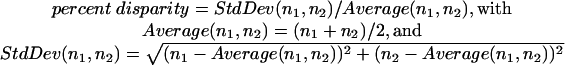 |
Table 1.
Summary of retardance area analysis on birefringent kinetochore fibers in control (untreated) spermatocytes.
| Bivalent type | Sister kinetochore pairs | Average number of microtubules per sister kinetochore pair | Average disparity between kinetochore fibers from the same bivalent to opposite poles |
|---|---|---|---|
| Disyntelic (n = 18) | Syntelic | 64 ± 16 (n = 36) | 14% |
Table 2.
Summary of retardance area analysis on birefringent kinetochore fibers in cold-recovering spermatocytes.
| Bivalent type | Sister kinetochore pairs | Average number of microtubules per sister kinetochore pair | Average disparity between kinetochore fibers from the same bivalent to opposite poles |
|---|---|---|---|
| Disyntelic (n = 22) | Syntelic | 66 ± 19 (n = 44) | 17% |
| Amphisyntelic and monodisyntelic with merotely (n = 9) | Syntelic | 62 ± 26 (n = 9) | |
| Amphitelic and syntelic with merotely | 84 ± 37 (n = 9) | 70% for all amphisyntelic and monodisyntelic with merotely |
The values given in Tables 1 and 2 are average percent disparities for bivalents within each of the indicated categories.
Finally, distances along the microscope axis, or Z-distances, were measured based on stage travel required to bring specimen features into focus. Z-distance was taken equal to stage travel multiplied by a factor of 0.88 to correct for the effect of the refractive index mismatch between the immersion oil (n=1.52) of the objective and the aqueous medium (n=1.36) of the spermatocyte preparation (Oldenbourg et al.,1998).
RESULTS
The crane fly, Nephrotoma suturalis, has eight chromosomes: three pairs of morphologically similar metacentric autosomes and two sex chromosomes (X and Y). In primary spermatocytes, the autosomes normally pair to form three bivalents. Sex chromosomes also pair during meiotic prophase, but they precociously disjoin at the prophase-prometaphase transition and are found as univalents during the course of meiosis I. The autosomal bivalents and their attachments to the spindle via kinetochore fibers are the subjects of the present study.
Metaphase Bivalents Normally Display Disyntelic Orientation
Each bivalent at metaphase has four kinetochores, one per chromatid. Sister kinetochores normally are paired and connected via their kinetochore fibers to the same pole, an arrangement called syntelic orientation. Disyntelic orientation (Figure 1A) is when a bivalent has each pair of sisters oriented to opposite poles, as is normally the case during meiosis I. For background regarding terminology (i.e., syntely, etc.), see Janicke and LaFountain, (1986). Because of their disyntelic orientation, paired homologues normally segregate away from each other toward opposite poles (Figure 1B).
Figure 1.

Drawings of bivalents exhibiting different microtubule connections between kinetochores and spindle poles. (A) Disyntelic orientation: the two sister kinetochores (K1) of one homologue within the bivalent are oriented to one pole (P1), and the paired sister kinetochores (K2) of the other homologue are oriented to the opposite pole (P2). (B) Upon disjunction, anaphase proceeds, and the two homologues segregate to opposite poles. (C) Amphisyntelic orientation: one pair of sister kinetochores (K2) is oriented with syntelic orientation to P2, and each kinetochore within the other pair (K1) is oriented to opposite poles with amphitelic orientation, resulting in two kinetochore fibers: K1P1 directed to one pole and K1P2 directed to the opposite pole. (D) Upon disjunction, anaphase proceeds, and the pair of sister kinetochores exhibiting syntelic orientation segregates to P2, whereas the other amphitelically oriented homologue lags at the equator. (E) Monodisyntelic with merotelic orientation: both pairs of sister kinetochores (K1 and K2) are oriented to the same pole (P1), but one of the sisters of one pair (K2) exhibits merotelic orientation to both poles (P1 and P2). (F) Upon disjunction, both half-bivalents segregate to the same pole (P1), with the merotelic half-bivalents lagging somewhat behind its partner. (G) Monodisyntelic orientation: both pairs of sister kinetochores are oriented to the same pole, and during anaphase (H), both half-bivalents segregate to the same pole.
Establishment of proper orientation takes place during prometaphase of meiosis I, a stage that lasts ∼1.5 h, after disintegration of the nuclear envelope at the prophase (diakinesis)/prometaphase transition. Bivalents previously attached to the nuclear envelope (LaFountain, 1983) are released into the forming spindle at diverse locations relative to the spindle equator and the two spindle poles. As prometaphase continues, bivalents congress to the spindle equator (see Figure 2 in Janicke and LaFountain, 1986) and normally become stably positioned midway between the spindle poles. The spindle widens at the equator to produce the defining bicone shape of the metaphase spindle (Figure 2). As they congress to the equator, bivalents in crane-fly spermatocytes do not exhibit oscillatory movement (directional instability) that is characteristic of chromosomes undergoing mitosis, especially in vertebrates (Skibbens et al., 1993).
Kinetochore fibers at metaphase exhibit birefringence that is much greater than that of the spindle background (Figure 2, A and B), a pattern shown in earlier work to be paralleled by the spatial distribution of densely packed kinetochore microtubules within highly birefringent fibers and sparsely packed nonkinetochore microtubules of the spindle background seen via thin-section electron microscopy (LaFountain, 1974). Where both sister kinetochores and their attached fibers are included in the same focal plane (Figure 2B), two distinct fibers can be resolved, one per kinetochore. Usually, however, those two fibers are so closely apposed and/or slightly tilted with respect to the focal plane that the two fibers appear as one (Figure 2A; Supplementary Video 2). For a given bivalent, the polarized light image of one of its kinetochore fibers to one pole is essentially a mirror image of its partner fiber to the other pole.
Length determinations of individual kinetochore microtubules cannot be made from polarized light images. Nevertheless, length profiles of birefringent fibers correlate well with data from an earlier thin-section EM study (Scarcello et al., 1986), which showed that kinetochore-to-pole connections are made by long, individual microtubules. Although the EM data came from few cells, it is suspected that finding pertains to spermatocytes in general, including those during cold recovery (considered below). Thus, for a kinetochore fiber of a metaphase bivalent, the total microtubule polymer is expected to be proportional to the number of microtubules in the fiber. We found in untreated control cells that total polymer in each partner fiber is approximately equal, based on data from retardance area analysis (see below) and the fact that length profiles of partner fibers in Z-focus series are virtually identical (Figure 2).
To evaluate the microtubule composition of each kinetochore fiber, we used an algorithm that computed “retardance area” within the domain of each kinetochore fiber that was selected (Figure 2C; see Materials and Methods). As shown by Oldenbourg et al. (l998), the retardance area is directly proportional to the number of microtubules in a fiber, with each microtubule contributing ∼7.5 nm2 to the retardance area of a fiber that is oriented parallel to the focal plane. For improving our estimates of kinetochore microtubules, we also accounted for the angle by which each kinetochore fiber was inclined to the focal plane (see Materials and Methods).
Among the six control cells analyzed at metaphase (18 bivalents; 36 kinetochore fibers), retardance area data were similar to those presented in Figure 2D, with an average of 64 ± 16 (range: 33–103, n = 36) kinetochore microtubules per sister kinetochore pair (Table 1). As with the cell illustrated in Figure 2, for a given bivalent, there was disparity in the number of kinetochore microtubules to opposite poles, ranging between 0 and 44%, with an average disparity of 14% (Table 1). For comparison, data from two earlier EM studies in which kinetochore microtubules were tracked and counted in transversely sectioned fixed cells were 79 ± 8 (range: 68–93, n = 13) kinetochore microtubules per sister kinetochore pair (LaFountain, 1976) and 101 ± 13 (range: 82–116, n = 6) kinetochore microtubules per sister kinetochore pair (Janicke and LaFountain, 1986), with 10% average disparity among the latter three pairs of sisters in the number of kinetochore microtubules from the same bivalent to opposite poles.
During Recovery from Meiotic Arrest, Bivalents Exhibit Stable Metaphase Malorientations
Cold treatments were used to induce bivalent malorientations. Spermatocytes in cold-treated larvae become arrested in a stage we call c-prometaphase (Janicke and LaFountain, 1982). At 0–2°C, spermatocytes progress through the prophase/prometaphase transition, but because microtubule assembly is inhibited, bivalents become dispersed, and no spindle forms. During cold recovery, many arrested spermatocytes within a given testis resume meiosis I synchronously (Janicke and LaFountgain, 1982), and bivalents, having diverse positions relative to the spindle poles and equator of the forming spindle, undergo congression to reach the metaphase plate. Anaphase in previously c-prometaphase cells commences after ∼45 min of recovery. For an account of the behavior of bivalents during cold recovery, see Janicke and LaFountain (1986).
It is common for bivalents during cold recovery to appear unusually tilted with respect to the spindle axis at metaphase (Figure 1, C, E, and G). Tilting is a consequence of improper orientation of kinetochores (malorientation). Such cold-induced malorientations persist into anaphase, leading to anomalous half-bivalent segregation, or anaphase lagging (Janicke and LaFountain, 1984).
Our intention at the outset of this study was to induce bivalents with three kinetochores oriented to one pole and only one kinetochore oriented to the other pole, a condition called amphisyntelic orientation (Figures 1C and 3). However, during the course of the work two additional malorientations having relevance to the study were recorded. One of those was interpreted as monodisyntelic orientation with merotely, an orientation in which sister kinetochores of both homologues have attachments to just one pole (monodisyntely), yet one of the kinetochores exhibits merotely and is connected to both poles (Figures 1E and 4, A and B). In addition, most unexpectedly, we recorded two metaphase bivalents that appeared to have both pairs of sister kinetochores directed to just one pole (Figures 1G and 4, C and D), thereby exhibiting monodisyntelic orientation.
Figure 4.

Birefringent kinetochore fibers of bivalents exhibiting monodisyntelic orientations. (A and B) Two slices from the Z-series made through cell 70 at focus steps of 0.26 μm give an example of a bivalent exhibiting monodisyntelic orientation with merotely. Cold treatment: 23.5 h. (A) Z-series 141; slice 27/46 illustrates syntelic orientation (white arrowhead) to the lower pole and merotelic orientation (black arrowhead) to the upper pole; (B) slice 31/46 illustrates syntelic orientation (arrowhead) to the lower pole. Time elapsed after the initiation of cold recovery: 50 min. Bar, 5 μm. (C and D) Two slices from the Z-series made through cell 67 at focus steps of 0.26 μm to give an example of monodisyntelic orientation. Cold treatment: 24 h (C) Z-series 138, slice 20/42; the kinetochore fiber from one pair of sister kinetochores (arrowhead) extends to the upper pole; (D) slice 37/42, the kinetochore fiber from the other pair of sisters (arrowhead) also extends to the upper pole. Time elapsed after the initiation of cold recovery: 67 min.
Besides appearing unusually tilted at metaphase, the above anomalous orientations were confirmed by the segregation patterns of the half-bivalents derived from them during anaphase. Bivalents exhibiting amphisyntely at metaphase contributed an amphitelically oriented laggard (Figures 1D and 3, DIC). The ultimate fate of such laggards is variable: some shift poleward long after the completion of anaphase A during cytokinesis, whereas others remain at the equator during cytokinesis, which invariably aborts probably because of the hindrance imposed by the laggard (Janicke and LaFountain, 1982). Here we tracked laggards only through the completion of anaphase A (Figure 5, E and K), and thus, any poleward shifting that may have occurred afterward during cytokinesis was not recorded. Both half-bivalents derived from bivalents with monodisyntelic orientation (with or without merotely) segregated along with their partners to the same pole (Figure 1, F and H; Figure 5, M and N; and Figure 5, T and U).
Figure 5.

All 11 of the maloriented bivalents that were analyzed are included in this gallery of 2-D projections. Z-series of each cell were projected to scale to give a profile of each bivalent's metaphase position relative to the long axis of the spindle. Two dots locate the flagellar basal bodies at the spindle poles, and the dashed line marks the plane half way between the two dots and regarded to be the spindle equator; maloriented bivalents are dark gray; other bivalents are light gray (dark gray overlaps light gray). Dark gray numbers near kinetochore fibers indicate the number of kinetochore microtubules in that fiber, based on retardance area analysis including corrections for inclination angle. The same type of analysis resulted in the light gray numbers, indicating the number of kinetochore microtubules associated with the two remaining bivalents in each cell that showed the correct orientation to the spindle poles. (A and B) Cell 6. Duration of cold treatment: 25.5 h. (A) Z-series 19 made 46 min after initiation of recovery. The dark gray bivalent exhibits amphisyntelic orientation. (B) Z-series 20 made 48 min after the initiation of recovery. Anaphase began 52 min after the initiation of recovery. Bar, 5 μm; all other projections (C–W) were made according to the same scale. (C–E) Cell 14. Duration of cold treatment: 46.5 h. (C) Z-series 54 made 35 min after initiation of recovery. The dark gray bivalent exhibits amphisyntelic orientation. (D) Z-series 56 made 42 min after the initiation of recovery. Anaphase began 45 min after the initiation of recovery. (E) Z-series 61 made 63 min after initiation of recovery. (F) Cell 47. Duration of cold treatment: 29 h. (F) Z-series 79 made 55 min after initiation of recovery. The dark gray bivalent exhibits amphisyntelic orientation. Anaphase began 62 min after the initiation of recovery. (G and H) Cell 49. Duration of cold treatment: 28 h. (G) Z-series 86 made 31 min after initiation of recovery. The dark gray bivalent exhibits amphisyntelic orientation. (H) Z-series 87 made 39 min after the initiation of recovery. Anaphase began 48 min after the initiation of recovery. (I–K) Cell 62. Duration of cold treatment: 26 h. (I) Z-series 118 made 71 min after initiation of recovery. The dark gray bivalent exhibits amphisyntelic orientation. (J) Z-series 119 made 76 min after the initiation of recovery. Anaphase began 80 min after the initiation of recovery. (K) Z-series 121 made 94 min after the initiation of recovery. (L) Cell 63. Duration of cold treatment: 29.5 h. (L) Z-series 122 made 49 min after initiation of recovery. The dark gray bivalent exhibits amphisyntelic orientation. Anaphase began 56 min after the initiation of recovery. (M and N) Cell 21. Duration of cold treatment: 95.5 h. (M) Z-series 8 made 54 min after initiation of recovery. The dark gray bivalent exhibits monodisyntelic orientation with merotely. Anaphase began 58 min after the initiation of recovery. (N) Z-series 13 made 90 min after the initiation of recovery. (O and P) Cell 66. Duration of cold treatment: 23 h. (O) Z-series 131 made 42 min after initiation of recovery. The dark gray bivalent exhibits monodisyntelic orientation with merotely. (P) Z-series 132 made 49 min after the initiation of recovery. Anaphase began 54 min after the initiation of recovery. (Q and R) Cell 70. Duration of cold treatment: 23.5 h. (Q) Projection of image 141D made 48 min after initiation of recovery. Only the position of the dark gray bivalent exhibiting monodisyntelic orientation with merotely is in this projection. (R) Z-series 141 made 51 min after the initiation of recovery. Anaphase began 51 min after the initiation of recovery. (S–U) Cell 67. Duration of cold treatment: 24 h. (S) Z-series 137 made 60 min after initiation of recovery. The dark gray bivalent exhibits monodisyntelic orientation. (T) Z-series 138 made 67 min after the initiation of recovery. Anaphase began 76 min after the initiation of recovery. (U) Z-series 141 made 98 min after the initiation of recovery. (V and W) Cell 72. Duration of cold treatment: 27 h. (V) Projection of image 154D made 35 min after initiation of recovery. Only the position of the dark gray bivalent exhibiting monodisyntelic orientation is available in this projection. (W) Z-series 154 made 38 min after the inititation of recovery. Anaphase began 47 min after the initiation of recovery.
A key feature of these malorientations in regard to this study was that they displayed stability at metaphase and did not reorient to a normal disyntelic orientation before anaphase onset. Many of the tilted bivalents that were initially recorded as potential candidates for the study did reorient, confirming that tendency which was noted previously (Janicke and LaFountain, 1986). Such reoriented malorientations were not subjected to further analysis (see below), but they did provide meaningful data regarding microtubules during the reorientation process, to be detailed in a future report.
Maloriented Bivalents Have Positions at the Spindle Equator at Metaphase
For each of the 11 maloriented bivalents that was analyzed, we prepared a profile of its position along the spindle axis. From the LC-PolScope images of each cell, the image of the bivalent in each of the optical sections of its Z-focus series was identified by eye, and the chromosome was marked by manually painting an image overlay. All overlays from a given Z-focus series were then collapsed into a single 2-D projection (see Materials and Methods). The projections show the positions of both maloriented and properly oriented bivalents, the positions of the centrosomal basal bodies, and the positions of the kinetochores of the maloriented bivalents (Figure 5). The plane of the equator is indicated in each (dashed line) as one half the distance between the flagellar basal bodies (indicated by dots) at the center of each centrosome.
Metaphase positions of maloriented bivalents (dark gray in Figure 5) were either at or near the equator. In most cases (i.e., in cells 6, 14, 49, 62, 66, 67, 70, and 72), both an initial position and another, final position just before anaphase onset were recorded to confirm stability. As detailed in the figure legend (Figure 5), anaphase commenced within 9 min after the final metaphase position was recorded.
Length profiles of kinetochore fibers of maloriented bivalents, in general, were not substantially different. By scrolling through Z-focus series, fibers can be tracked from their kinetochores to poles, demonstrating that a kinetochore-to-pole connection exists, just as in untreated cells. One reviewer pointed out that the syntelic fiber in slice 29/40 (Figure 3C) from cell 47 appeared shorter than others (e.g., the fibers in slice 15/40, Figure 3D). However, the “short” fiber in slice 29/40 had an inclination angle of 17° in relation to the focal plane and can be tracked all the way to the pole in adjacent slices (Figure 3 and Supplementary Video 3). Thus, although a fiber may appear to be short in one slice, additional portions of the fiber are contained in other Z slices, and its actual length is essentially equal to that of others.
An additional point not readily apparent from the 2-D projections is that bivalents during cold recovery, including 8 of the 11 that were maloriented, tended to be positioned in closer proximity to the spindle periphery than in untreated cells (Figures 2, 3, 4, and Supplementary Videos 2–4). This tendency was also noted in an earlier study (Janicke and LaFountain, 1986), and it may be significant because the domain of the spindle periphery is where polar ejection forces are operative (LaFountain et al., 2002; see Discussion). However, we also note exceptions represented by cells 21, 63, and 70, in which maloriented bivalents were located centrally in the spindle.
The Numbers of Microtubules Extending from Maloriented Bivalents to the Two Spindle Poles Are Different
Retardance area analysis of maloriented bivalents (Figures 3 and 5) revealed gross differences in the numbers of kinetochore microtubules extending from maloriented bivalents to the two spindle poles (Figures 3 and 5). For example, among the kinetochore fibers of the amphisyntelic bivalent in cell 47 (Figure 3), only ∼20% (43 microtubules) of all the kinetochore microtubules was directed to the lower pole (Figure 3, B and BB), and the vast majority of ∼80% (80 plus 100 microtubules) was directed to the upper pole (Figure 3, A and AA, and 3, C and CC). Similar unbalanced fiber arrangements were found among the other amphisyntelic bivalents (Figure 5, A–L), all of which, as described above, had positions at or near the spindle equator. Present data are remarkably consistent with kinetochore microtubule data obtained by tracking and counting microtubules in thin sections of fixed spermatocytes (Janicke and LaFountain, 1986). For example, amphisyntelic bivalent cIII (Figure 1) in that earlier EM study had 49 kinetochore microtubules to one pole and 196 to the other, data almost the same as those from cell 47 mentioned above.
Unbalanced arrays of kinetochore microtubules were even more pronounced among bivalents exhibiting monodisyntely with merotely (Figure 5, M–R). For example, in cell 66, monodisyntelic kinetochore microtubules accounted for 120 of the total, and the merotelic bundle contained only 11 microtubules. The merotelic bundle remained attached to its half-bivalent as the latter moved to the “wrong” pole during anaphase (Figure 5N). Taking all nine bivalents with bipolar malorientations (i.e., amphisyntelic and monodisyntelic with merotely) into account, the average disparity between kinetochore fibers from maloriented bivalents to the opposite poles was 70% (Table 2), substantially different from 14% for disyntelic bivalents in control cells (Table 1).
Unlike maloriented bivalents, properly oriented (disyntelic) bivalents in cold-recovering cells did not have such unbalanced fiber arrangements (Figure 5.) More importantly, as summarized in Table 2, the data for disyntelic bivalents in cold-recovering cells were similar to those from untreated cells (Table 1)—the average number of microtubules per sister kinetochore pair was 66 ± 19 vs. 64 ± 16 for controls and the average disparity between kinetochore fibers to opposite poles was 17 vs. 14% in controls—thus giving us confidence in both the sensitivity and accuracy of our method. An additional point regarding the data in Table 2 is that the number of microtubules per sister kinetochore pair for syntelically oriented sisters of maloriented bivalents was 62 ± 26 (n = 9), similar to what was obtained from disyntelic bivalents in both control and cold-recovering cells described above.
Taking into account all 11 of the bivalents in Figure 5, the total number of kinetochore microtubules per bivalent ranged between 74 and 223. In comparison to past EM data from control cells, where the number of kinetochore microtubules per sister kinetochore pair ranged between 68 and 116, only about one third of the bivalents in this study fall within the range expected based on EM data (range: 2 × 68 = 136 to 2 × 116 = 232). Although we have no ready explanation for why more cold-recovering cells do not meet this expectation, we suspect the results are due to variation within the different cells (obtained from different larvae) used in this study, as opposed to any variability in the analytical methods that were used.
Lastly, our finding of monodisyntelic bivalents (in cell 67: Figure 5T; in cell 72: Figure 5, V and W) stably positioned at the spindle equator is without precedent and has raised our concern about whether these two bivalents might actually have had merotelic kinetochores. It is generally thought that monodisyntelic bivalents always reorient to disyntelic orientations before anaphase onset. That clearly was not true for these two bivalents during cold recovery (Figure 4, C and D, and Supplementary Video 4), as each contributed two half-bivalents that segregated together to the same pole (Figure 5U). To address our concerns about the orientation of these two bivalents, we scrutinized the Z scans of each. Convincing evidence for merotely was not found in either case, although a merotelic fiber containing <10 microtubules would not necessarily have been detected as such by the LC-PolScope. Thus, even though we identify the bivalents here as monodisyntelic bivalents, we must acknowledge that each could have had a fiber containing fewer than 10 microtubules (and therefore be outside the detectablity range of the LC-PolScope) connecting a merotelic kinetochore to the opposite pole.
DISCUSSION
In brief, the traction fiber model relates the magnitude of poleward forces exerted on a chromosome to the number and length of kinetochore microtubules attached to it. For a stable metaphase position, the model requires that the total microtubule polymer to each of the opposite poles be equal (Hays and Salmon, 1990). Our observations of maloriented bivalents in crane-fly spermatocytes during cold recovery do not conform to that requirement.
Bivalents exhibiting bipolar malorientations (i.e., amphisyntely and monodisyntely with merotely) had grossly unbalanced kinetochore microtubule complements, based on analysis of retardance area. Disparities averaging 70% were found upon comparison of the number of kinetochore microtubules to one pole vs. the other.
Despite these disparities, all maloriented bivalents had stable positions near the spindle equator at metaphase, evident in the graphical displays presented in Figure 5. Consider, for example, the amphisyntelic bivalent in cell 47 (Figures 3 and 5F) that had 180 kinetochore microtubules to the upper pole and only 43 microtubules extending to the lower pole, a disparity of 87%. According to the traction fiber model, this bivalent should have a stable position near the upper pole. Instead, our observation shortly before the onset of anaphase showed it to have a stable position near the equator, along with the other two properly oriented bivalents, which had disparities of 42 and 3%.
Even monodisyntelic bivalents with attachments to only one pole had stable positions near the equator at metaphase (in cells 67 and 72, Figure 5, S–W). This is in contrast to earlier findings, which suggested that monodisyntelic bivalents always reorient to a disyntelic orientation before metaphase if not subjected to bipolar tension (Nicklas, 1997). In accordance with their monodisyntelic orientation, in both of those cells, the two half-bivalents derived from each mono-oriented bivalent moved to the same pole during anaphase. Although the possibility has not been completely ruled out that one of the kinetochores of either was merotelic with a fiber containing <10 microtubules connecting it to the opposite pole (see Results), nevertheless, each of these bivalents maintained a stable position near the equator at metaphase.
The traction fiber model—poleward pulling forces generated by matrix-associated motors acting along the lengths of kinetochore microtubules—is appealing based on its force-distance relationship, which explains congression in terms of a “tug of war” generated by oppositely directed kinetochore fibers (Östergren, 1950, 1951). According to Östergren, the longer traction fiber of a congressing bivalent tugs with greater force than the shorter fiber, until an equatorial position and force equilibrium is reached. Especially for meiosis, the model also provides a ready explanation for why bivalents do not oscillate at metaphase, as pole-directed forces are not directionally unstable (Skibbens et al., 1993). In contrast, mitotic chromosomes oscillate, a behavior explained by the interplay between motile kinetochores and polar ejection forces (Rieder and Salmon, 1994). Traction forces can also explain the mechanism of anaphase in spermatocytes (Wilson et al., 1994; Desai et al., 1998; LaFountain et al., 2001). In the “flux machine” model, force producers within the spindle are responsible for driving microtubules and associated chromosomes poleward (Sawin and Mitchison, 1991; Kapoor and Mitchison, 2001; Maddox et al., 2002; reviewed by Kapoor and Compton, 2002). Although kinetochore motors have also been implicated in the mechanism of anaphase in insect spermatocytes (Nicklas, 1989; Savoian et al., 2000), recent findings of Chen and Zhang (2004) are not in agreement.
Present findings do not rule out a traction fiber mechanism in generating poleward forces on bivalents. Rather, we have found that the traction fiber model, by itself, does not provide a satisfactory explanation of the results we have obtained. Therefore, we conclude that other factors, in addition to traction fibers, are required in the mechanism that positions maloriented bivalents on the metaphase plate. Two possibilities are considered below.
We know from earlier laser microsurgery studies (LaFountain et al., 2002) that bivalents are subject to polar ejection forces. Present results concerning maloriented bivalents suggest the possible involvement of ejection forces in achieving and maintaining their positions on the metaphase plate. A model for how ejection forces in concert with pole-directed traction forces are envisioned to participate in positioning bivalents normally in untreated cells has been published elsewhere (LaFountain et al., 2002).
When the laser microbeam was used to generate achiasmic arm fragments in the central domain of the spindle, they were initially transported poleward by microtubule flux–mediated forces. Then, upon being expelled to the spindle periphery by transverse equilibrium forces, they moved back to the equator (LaFountain et al., 2002). That congression of acentric chromosome fragments demonstrated that the forces acting upon them were kinetochore independent. When acentric fragments were generated from chromosome arms that extended into the polar ejection field at the spindle periphery, no poleward movement was observed. The latter type of fragment was immediately ejected to the spindle equator. A role for chromokinesins (e.g., human Kid, Xenopus Xkid) in generating polar ejection forces is backed by recent evidence (Antonio et al., 2000; Funabiki and Murray, 2000; Levesque and Compton, 2002); however, in the case of spermatocytes, we have no evidence in that regard.
Away-from-the-pole ejection forces could provide resistance preventing amphisyntelic bivalents from being located closer to the pole with more kinetochore microtubules. Likewise, they also would provide the counterforce required to maintain tension on mono-oriented bivalents, thus stabilizing the mono-orientation and preventing reorientation. The proviso in both of the cases above is that in order for a bivalent to be subject to the ejection field, it must be positioned at the spindle periphery. As noted, 8 of the 11 maloriented bivalents analyzed were positioned at the extreme periphery of the spindle, clearly within the domains of the polar ejection field. Maintenance of amphisyntelic and monodisyntelic bivalents at the spindle periphery very likely was achieved through the action of transverse equilibrium forces, which are directed outward from the central domain of the spindle toward the peripheral sheath of mitochondria that surrounds it.
Regardless of bivalent orientation, if the magnitude of the ejection forces on chromosome arms is greater than that of poleward forces exerted on kinetochores, then the action of the ejection field could conceivably congregate all of the bivalents (including those with monopolar orientations) at the spindle equator. Thus, the disparity of poleward forces generated by unbalanced traction fibers, or by traction fibers to only one pole, could be rendered mute by ejection forces of greater magnitude than the sum of all pole-directed forces. Similarly, ejection forces also may exert forces in this way on bivalents undergoing normal meiosis.
Ejection forces cease at anaphase onset, as a consequence of degradation of chromokinesin (Funabiki and Murray, 2000), and then disjoined syntelic half-bivalents (including those derived from monodisyntelic bivalents) move poleward. In the cases of amphitelic laggards during anaphase, when ejection forces cease, poleward flux forces direct the arms of laggards poleward, and by a mechanism not understood, laggards may shift poleward, after a delay, during cytokineis (Janicke and LaFountain, 1982).
Three of the maloriented bivalents in the study, namely in cells 21, 63, and 70 (Figure 5, L, M, and Q), were centrally located in the spindle and were spatially separated from the polar ejection field. The metaphase positions of those centrally located bivalents likely were achieved in the absence of polar ejection forces, calling into question how applicable the above traction fiber/polar ejection force model is to them.
Alternative ideas applicable to those centrally located bivalents are contained in the smart kinetochore model (Mitchison, 1989). Although amended by others (Skibbens et al., 1993, 1995; Rieder and Salmon, l998), the original model suggested that during mitosis smart kinetochores embody the necessary sensory and motile molecules to detect positional information and then use that information to control kinetochore activity. A suggested source of positional information is a gradient of some unknown factor(s) within the spindle. Each kinetochore may sense its position in the gradient independently and then responds accordingly. Communication between smart kinetochores on a given chromosome appears in recent revisions put forth to explain the oscillatory switching between states of kinetochore activity (Skibbens et al., 1995), but computer simulations made by Khodjakov et al. (1999) indicate that such communication may not be necessary. Smart kinetochores have been implicated recently in the mechanism of congression in Kid-depleted cells (Levesque and Compton, 2001).
Applying the model to meiosis, bivalents have stable metaphase positions at the equator because the concentration of unknown factor(s) sensed by all four bivalent kinetochores at the equator causes them to be in a nonmotile state. Smart kinetochores in off-equatorial regions of the spindle would be expected to sense different concentrations of factor(s), which would stimulate congression to the equator. Speculation into how congression of bivalents could be achieved using smart kinetochores, however, is outside the bounds of this discussion.
Because meiotic bivalents do not oscillate at metaphase, kinetochores of stably positioned bivalents likely are in a “neutral (N) state” (Skibbens et al., 1993), in which they are actively engaged to kinetochore microtubule plus ends but are motionless. In the N state, kinetochore microtubules would be expected to exhibit flux, with the slippage of fluxing microtubules through kinetochores possibly generating tension (LaFountain et al., 2001) but clearly not generating sufficient poleward force to shift a bivalent in the direction having more kinetochore microtubules. In this way, the smart kinetochore model can explain metaphase positioning of most of the maloriented bivalents reported here as well as properly oriented bivalents in untreated spermatocytes. In the cases of monodisyntelic bivalents, a positioning mechanism based solely on smart kinetochores is insufficient, and counterforce supplied by polar ejection forces may be essential, as discussed above.
Unfortunately, however, there is not complete agreement between the model and results cited above from the earlier work by Hays and Salmon (1990) on grasshopper spermatocytes, showing that ablation of one of the four kinetochores of a congressed bivalent causes it to shift to a stable, off-equatorial position. Hence, although smart kinetochores, and polar ejection forces discussed above, are possible factors participating in the metaphase positioning of bivalents during meiosis, neither is compatible with all of the data.
In conclusion, it is important to emphasize that we have not attempted to evaluate the traction fiber model in congression, per se. Bivalents analyzed here were selected in spermatocytes during cold recovery based on their unusual tilt relative to the spindle axis. All of the tilted bivalents that we located for this study were already positioned at or near the equator. Thus, we do not know whether the equatorial position of a selected bivalent was the result of congression from a distant location or was the initial position of the bivalent at the onset of recovery. It is clear from our earlier work on bivalent behavior during cold recovery (Janicke and LaFountain, 1986) that wide-ranging movement of bivalents within cold-recovering spindles is indeed possible, just as in control (untreated) cells. It is most important to the present study, however, that maloriented bivalents subjected to analysis were stably positioned at the spindle equator and did not shift poleward or undergo reorientation before the onset of anaphase. The latter possibility was an unresolved question left after our earlier study of bivalent malorientation in fixed cells (Janicke and LaFountain, 1986). In the present study, we have used living cells to demonstrate that reorientation or shifting of grossly unbalanced malorientations does not occur and that such malorientations are stable at the spindle equator. A test of the traction fiber model during congression occurring in mitotic cells has been performed (McEwen et al., 1997), but to date the model has not been evaluated with congressing bivalents in any type of meiotic cell.
Supplementary Material
Acknowledgments
We thank Alan Siegel for assistance in making Figure 1 and Douglas LaFountain for valuable input. J.R.L. is supported by grant MCB-0235934 from the National Science Foundation. R.O. is supported by grants GM49210 from the National Institute of General Medical Sciences and EB002045 from the National Institute of Biomedical Imaging and Bioengineering.
Article published online ahead of print. Mol. Biol. Cell 10.1091/mbc.E04–06–0524. Article and publication date are available at www.molbiolcell.org/cgi/doi/10.1091/mbc.E04–06–0524.
The online version of this article contains supplemental material at MBC Online (http://www.molbiolcell.org).
References
- Antonio, C., Ferby, I., Wilhelm, H., Jones, M., Karsenti, E., Nebreda, A.R., and Vernos, I. (2000). Xkid, a chromokinesin required for chromosome alignment on the metaphase plate. Cell 102, 425–435. [DOI] [PubMed] [Google Scholar]
- Begg, D.A., and Ellis, G.W. (l979). Micromanipulation studies of chromosome movement. II. Birefringent chromosomal fibers and the mechanical attachment of chromosomes to the spindle. J. Cell Biol. 82, 542–554. [DOI] [PMC free article] [PubMed] [Google Scholar]
- Born, M., and Wolf, E. (1980). Principles of Optics, Elmsford, NY: Pergamon Press.
- Chen, W., and Zhang, D. (2004). Kinetochore fiber dynamics outside the context of the spindle during anaphase. Nat. Cell Biol. 6, 227–231. [DOI] [PubMed] [Google Scholar]
- Desai, A., Maddox, P.S., Mitchison, T.J., and Salmon, E.D. (1998). Anaphase A chromosome movement and poleward spindle microtubule flux occur at similar rates in Xenopus extract spindles. J. Cell Biol. 141, 703–713. [DOI] [PMC free article] [PubMed] [Google Scholar]
- Funabiki, H., and Murray, A.W. (2000). The Xenopus chromokinesin Xkid is essential for metaphase chromosome alignment and must be degraded to allow anaphase chromosome movement. Cell 102, 411–424. [DOI] [PubMed] [Google Scholar]
- Hays, T.S., Wise, D., and Salmon, E.D. (1982). Traction force on a kinetochore at metaphase acts as a linear function of kinetohcore fiber length. J. Cell Biol. 93, 374–389. [DOI] [PMC free article] [PubMed] [Google Scholar]
- Hays, T.S., and Salmon, E.D. (1990). Poleward force at the kinetochore in metaphase depends on the number of kinetochore microtubules. J. Cell Biol. 110, 391–404. [DOI] [PMC free article] [PubMed] [Google Scholar]
- Janicke, M.A., and LaFountain, J.R., Jr. (1982). Chromosome segregation in crane-fly spermatocytes: cold treatment and cold recovery induce anaphase lag. Chromosoma (Berl.) 85, 619–631. [DOI] [PubMed] [Google Scholar]
- Janicke, M.A., and LaFountain, J.R., Jr. (1984). Malorientaton in half-bivalents at anaphase: analysis of autosomal laggards in untreated, cold-treated, and cold-recovering crane fly spermatocytes. J. Cell Biol. 98, 859–869. [DOI] [PMC free article] [PubMed] [Google Scholar]
- Janicke, M.A., and LaFountain, J.R., Jr. (l986). Bivalent orientation and behavior in crane-fly spermatocytes recovering from cold exposure. Cell Motil. Cytoskelet. 6, 492–501. [DOI] [PubMed] [Google Scholar]
- Kapoor, T.M., and Mitchison, T.J. (2001). Eg5 is static in bipolar spindles relative to tubulin: evidence for a static spindle matrix. J. Cell Biol. 154, 1125–1133. [DOI] [PMC free article] [PubMed] [Google Scholar]
- Kapoor, T.M., and Compton, D.A. (2002). Searching for the middle ground: mechanisms of chromosome alignment during mitosis. J. Cell Biol. 157, 551–556. [DOI] [PMC free article] [PubMed] [Google Scholar]
- Khodjakov, A., Gabashvili, I.S., and Rieder, C.L. (1999). “Dumb”versus “smart” kinetochore models for chromosome congression during mitosis in vertebrate somatic cells. Cell Motil. Cytoskelet. 43, 179–185. [DOI] [PubMed] [Google Scholar]
- LaFountain, J.R. (1974). Birefringence and fine structure of spindles in spermatocytes of Nephrotoma suturalis at metaphase of the first meiotic division. J. Ultrastruct. Res. 46, 268–278. [DOI] [PubMed] [Google Scholar]
- LaFountain, J.R. (1976). Birefringence and ultrastructure of spindles in primary spermatocytes of Nephrotoma suturalis during anaphase. J. Ultrastruct. Res. 54, 333–346. [DOI] [PubMed] [Google Scholar]
- LaFountain, J.R., Jr. (1983). Chromosome movement during meiotic prophase in crane-fly spermatocytes. II. Analysis of polarization of chromosomes and their association with the nuclear envelope. Cell Motil. 3, 261–271. [Google Scholar]
- LaFountain, J.R., Jr., Oldenbourg, R., Cole, R.W., and Rieder, C.L. (2001). Microtubule flux mediates poleward motion of acentric chromosome fragments during meiosis in insect spermatocytes. Mol. Biol. Cell 12, 4054–4065. [DOI] [PMC free article] [PubMed] [Google Scholar]
- LaFountain, J.R., Jr., Cole, R.W., and Rieder, C.L. (2002). Polar ejection forces are operative in crane-fly spermatocytes, but their action is limited to the spindle periphery. Cell Motil. Cytoskelet. 51, 16–26. [DOI] [PubMed] [Google Scholar]
- Levesque, A.A., and Compton, D.A. (2001). The chromokinesin Kid is necessary for chromosome arm orientation and oscillation, but not congression, on mitotic spindles. J. Cell Biol. 154, 1135–1146. [DOI] [PMC free article] [PubMed] [Google Scholar]
- Maddox, R., Desau, A., Oegema, K., Mitchison, T.J., and Salmon, E.D. (2002). Poleward microtubule flux is a major component of spindle dynamics and anaphase A in mitotic Drosophila embryos. Curr. Biol. 12, 1670–1674. [DOI] [PubMed] [Google Scholar]
- McEwen, B.F., Heagle, A.B., Cassels, G.O., Buttle, K.F., and Rieder, C.L. (1997). Kinetochore fiber maturation in PtK1 cells and its implication for the mechanisms of chromosome congression and anaphase onset. J. Cell Biol. 137, 1567–1580. [DOI] [PMC free article] [PubMed] [Google Scholar]
- Mitchison, T.J. (1989). Chromosome alignment at mitotic metaphase: balanced forces or smart kinetochores? In: Cell Movement, Vol. 2, Kinesin, Dynein, and Microtubule Dynamics, ed. D.F. Warner, J.R. McIntosh, New York: Alan Liss, 421–430. [Google Scholar]
- Nicklas, R.B. (1989). The motor for poleward chromosome movement in anaphase is in or near the kinetochore. J. Cell Biol. 109, 2245–2255. [DOI] [PMC free article] [PubMed] [Google Scholar]
- Nicklas, R.B. (1997). How cells get the right chromosomes. Science 275, 632–637. [DOI] [PubMed] [Google Scholar]
- Oldenbourg, R., Salmon, E.D., and Tran, P.T. (1998). Birefringence of single and bundled microtubules. Biophys. J. 74, 645–654. [DOI] [PMC free article] [PubMed] [Google Scholar]
- Oldenbourg, R. and Mei, G. (1995). New polarized light microscope with precision universal compensator. J. Microsc. 180, 140–147. [DOI] [PubMed] [Google Scholar]
- Östergren, G. (1950). Considerations on some elementary features of mitosis. Hereditas 36, 1–18. [Google Scholar]
- Östergren, G. (1951). The mechanism of co-orientation in bivalents and multivalents. The theory of pulling. Hereditas 37, 85–156. [Google Scholar]
- Pickett-Heaps, J.D., Forer, A., and Spurck, T. (1996). Rethinking anaphase: where “pac-man” fails and why a role for the spindle matrix is likely. Protoplasma 192, 1–10. [Google Scholar]
- Rieder, C.L., and Salmon, E.D. (1994). Motile kinetochores and polar ejection forces dictate chromosome position on the vertebrate mitotic spindle. J. Cell Biol. 124, 223–233. [DOI] [PMC free article] [PubMed] [Google Scholar]
- Rieder, C.L., and Salmon, E.D. (1998). The vertebrate cell kinetochore and its role during mitosis. Trends Cell Biol. 8, 310–318. [DOI] [PMC free article] [PubMed] [Google Scholar]
- Savoian, M.S., Goldberg, M.L., and Rieder, C.L. (2000). The rate of poleward chromosome motion is attenuated in Drosophila zw10 and rod mutants. Nat. Cell Biol. 2, 948–952. [DOI] [PubMed] [Google Scholar]
- Sawin, K.E., and Mitchison, T.J. (1991). Poleward microtubule flux in mitotic spindles assembled in vitro. J. Cell Biol. 112, 941–954. [DOI] [PMC free article] [PubMed] [Google Scholar]
- Scarcello, L.A., Janicke, M.A., and LaFountain, J.R. (1986). Kinetochore microtubules in crane-fly spermatocytes: untreated, 2°C treated, and 6°C grown spindles. Cell Motil. Cytoskelet. 6, 428–438. [DOI] [PubMed] [Google Scholar]
- Skibbens, R.V., Skeen, V.P., and Salmon, E.D. (1993). Directional instability of kinetohcore motility during chromosome congression and segregation in mitotic newt lung cells: a push-pull mechanism. J. Cell Biol. 122, 859–875. [DOI] [PMC free article] [PubMed] [Google Scholar]
- Skibbens, R.V., Rieder, C.L., and Salmon, E.D. (1995). Kinetochore motility after severing between sister centromeres using laser microsurgery: evidence that kinetochore directional instability and position is regulated by tension. J. Cell Sci. 108, 2537–2548. [DOI] [PubMed] [Google Scholar]
- Wilson, P.J., Forer, A., and Leggiadro. (1994). Evidence that kinetochore microtubules in crane-fly spermatocytes disassemble during anaphase primarily at the poleward end. J. Cell Sci. 107, 3015–3027. [DOI] [PubMed] [Google Scholar]
Associated Data
This section collects any data citations, data availability statements, or supplementary materials included in this article.