Abstract
Membrane localization domain (MLD) was first proposed for a 4‐helix‐bundle motif in the crystal structure of the C1 domain of Pasteurella multocida toxin (PMT). This structure motif is also found in the crystal structures of several clostridial glycosylating toxins (TcdA, TcdB, TcsL, and TcnA). The Ras/Rap1‐specific endopeptidase (RRSP) module of the multifunctional autoprocessing repeats‐in‐toxins (MARTX) toxin produced by Vibrio vulnificus has sequence homology to the C1‐C2 domains of PMT, including a putative MLD. We have determined the solution structure for the MLDs in PMT and in RRSP using solution state NMR. We conclude that the MLDs in these two toxins assume a 4‐helix‐bundle structure in solution.
Keywords: Pasteurella multocida, Vibrio vulnificus, bacterial toxin, membrane localization domains, solution NMR spectroscopy, 4‐helix‐bundle
Short abstract
Abbreviations
- MARTX
multifunctional autoprocessing repeats‐in‐toxins
- MLD
membrane localization domain
- PMT
Pasteurella multocida toxin
- RRSP
Ras/Rap1‐specific endopeptidase
Introduction
Pathogenic bacteria produce a number of toxins that influence host–pathogen interactions to aid survival within a host.1 These toxins range in size from small molecules to large proteins and confer toxicity to hosts by targeting different cellular components and processes. Many bacterial toxins consist of an effector domain that requires a receptor‐binding domain to reach specific cells and an additional translocation domain to facilitate delivery of the effector domain into the cytosol, where it gains access to its intracellular targets.
The heterotrimeric G‐protein‐deamidating toxin from Pasteurella multocida (PMT) is a 150 kDa protein comprised of N‐terminal receptor‐binding and translocation domains (residues 1–568)2, 3 and C‐terminal activity domains (residues 569–1285). The crystal structure of the C‐terminal region is resolved into C1 (residues 569–719), C2 (residues 720–1104), and C3 (residues 1105–1284) domains.4 The Gα‐protein‐deamidase activity of PMT was localized to the C3 domain.5, 6 The C1 domain contains a 4‐helix‐bundle motif (residues 589–668) that was shown to have membrane‐targeting properties capable of bringing GFP to the plasma membrane.4, 7 This structural motif was also observed in the clostridial glycosylating toxins (Fig. 1), including TcdA, TcdB, TcsL, and TcnA.8, 9, 10, 11
Figure 1.
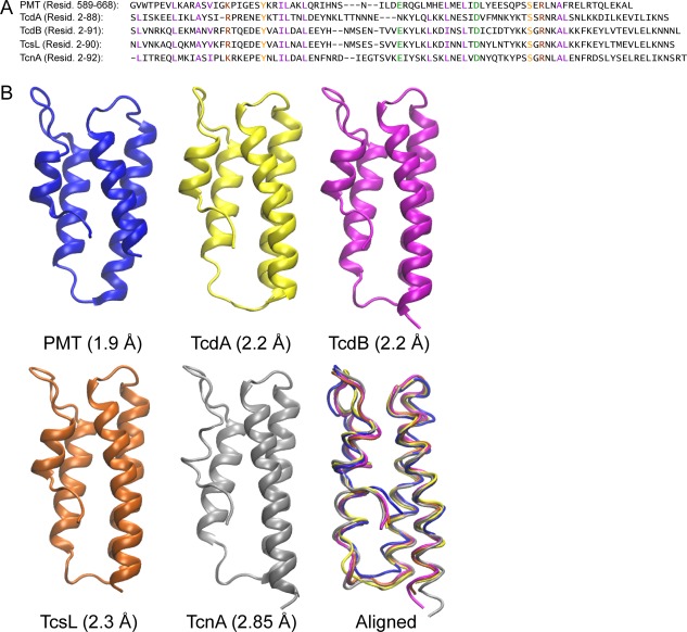
Comparison of sequences and crystal structures of putative MLDs in bacterial toxins. (A) Amino acid sequence alignment with conserved residues color coded (purple: hydrophobic, brown: basic, green: acidic, orange: polar) and (B) the corresponding crystal structures of the individual and aligned 4‐helix‐bundle motifs found in PMT (PDB ID: 2EBF), TcdA (PDB ID: 3SS1), TcdB (PDB ID: 2BVL), TcsL (PDB ID: 2VL8), and TcnA (PDB ID: 2VK9).
Similar sequences have been found in other bacterial toxins,12 a number of which have been shown to confer membrane localization of adjacent effector domains, and are referred to as membrane localization domains (MLDs).13 The MLD and its adjacent effector domain from a MARTX toxin of Vibrio vulnificus (Ras and Rap1‐specific endopeptidase RRSP; formerly DUF5) have the strongest homology to the C1‐C2 domains of PMT.14, 15 A crystal structure of the MLDRRSP alone (PDB 4ERR) is available, but this structure differs from the structure observed in the crystal structures with other domains present (PDB ID: 2EBF,4 3SS1,10 2BVL,9 2VL8,8 2VK911).
Considering the importance of this MLD motif in three classes of diverse toxins,13 a question arises regarding the solution structure of the MLDs. Thus, we determined the solution structures of MLDPMT and MLDRRSP using solution state NMR spectroscopy and compare the solution structures to the MLD moiety to that found in the crystal structures.
Results
Structure of MLDPMT
MLDPMT contains 79 residues [Fig. 2(A)]. In a previous study, predicted dihedral angles, determined by TALOS+, indicated that MLDPMT contains four helices.16 For this study, the improved TALOS‐N program was used to predict dihedral angles and order parameters [Fig. 2(B)].17 Similar to the TALOS+ results, the dihedral angle prediction indicates that MLDPMT forms four helices. Furthermore, the order parameter predictions indicate that the loop and termini residues experience greater mobility as compared to the helical residues.
Figure 2.
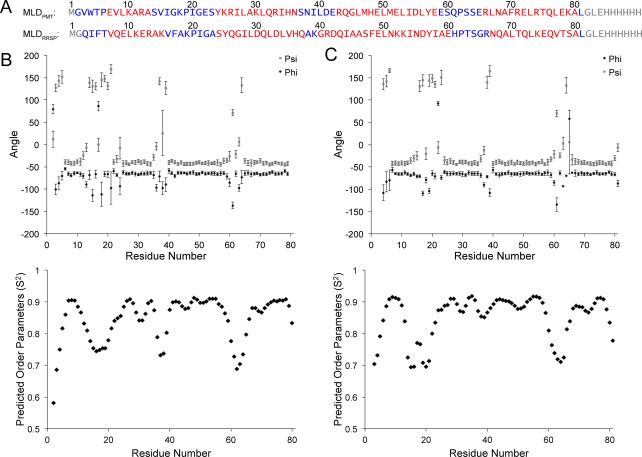
Secondary structures and dynamics determined by TALOS‐N. (A) Amino acid sequence alignment of MLDPMT and MLDRRSP. Non‐native termini residues are in grey, loop residues are in blue, and helix residues are in red. Dihedral angles (φ, ψ) and order parameters of MLDPMT (B) and MLDRRSP (C), predicted from TALOS‐N are plotted.
The overall fold of the solution structure is a 4‐helix‐bundle [Fig. 3(A)]. Of the top 20 structures (out of 200 total), the backbone RMSD of the ordered residues (corresponding to the helix residues) was determined to be 0.99 Å. Table 1 summarizes the statistics regarding the ensemble of structures. The ensemble of structures has an average of 2.6 ± 1.3 energy violations. Ramachandran analysis determined that 86.1% ± 2.8% of the residues were in favored regions, where violations were found in the mobile loop regions.
Figure 3.
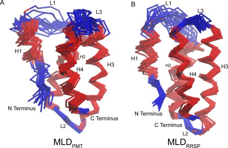
Alignment of top 20 solution structures of MLDPMT and MLDRRSP. Three‐dimensional superposition of the top 20 structures of MLDPMT (A) and MLDRRSP (B), as determined using solution state NMR. The backbone RMSD of the helix residues of MLDPMT is 0.99 Å and of MLDRRSP is 0.96 Å.
Table 1.
Restraints and Statistics of Top 20 Structures
| NMR distance restraints | MLDPMT | MLDRRSP |
|---|---|---|
| Total NOE | 1485 | 1256 |
| Intra‐residue NOE | 606 | 492 |
| Inter‐residue NOE | 503 | 445 |
| Sequential (|i − j| = 1) | 238 | 180 |
| Medium‐range (|i − j| < 4) | 156 | 151 |
| Long‐range (|i − j| ≥ 5) | 109 | 114 |
| Ambiguous NOE | 376 | 319 |
| Dihedral angle restraints | ||
| ϕ (TALOS‐N) | 75 | 73 |
| ψ (TALOS‐N) | 75 | 73 |
| Violations | ||
| Total violations | 2.6 ± 1.3 | 0.1 ± 0.3 |
| NOE violations | 0 | 0 |
| CDIH violations | 2.3 ± 1.2 | 0 |
| van der Waals violations | 0.3 ± 0.6 | 0.1 ± 0.3 |
| Deviations from idealized geometry | ||
| Bond lengths (Å) | 0.003 ± 0.000 | 0.002 ± 0.000 |
| Bond angles (°) | 0.449 ± 0.010 | 0.380 ± 0.006 |
| Impropers (°) | 0.337 ± 0.013 | 0.246 ± 0.015 |
| Ramachandran plot statistics (Molprobity) | ||
| Favored region (%) | 89.6 | 98.7 |
| Allowed region (%) | 8.1 | 1.2 |
| Disallowed region (%) | 2.2 | 0.1 |
| RMSD (ordered residues) | ||
| Backbone RMSD (Å) | 0.97 | 0.97 |
| Heavy Atom RMSD (Å) | 1.76 | 1.73 |
As reported in Table 1, 1485 NOE restraints were used to calculate the structure. Of those NOE peaks, 109 were long‐range peaks that helped to define the interhelical contacts. For example, contacts between E7 to L28 define the helix 1 and 2 interface, I34 to L46 for helix 2 and 3, L47 to L77 for helix 3 and 4, and L9 to F70 for helix 1 and 4. These contacts are depicted on a representative structure [Fig. 4(A)], with the lowest RMSD with respect to the bundle of 20 structures.
Figure 4.
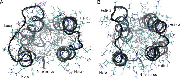
Interhelical NOEs of MLDPMT and MLDRRSP. Interhelical NOE contacts are mapped onto the structures of MLDPMT (A) and MLDRRSP (B). Contacts in MLDPMT include E7 to L28 (H1‐H2), I27 to Y57 (H2‐H3), I34 to L46 (H2‐H3), M47 to L77 (H3‐H4), I54 to R74 (H3‐H4), and L9 to F70 (H1‐H4). Contacts in MLDRRSP include V7 to L29 (H1‐H2), I28 to Y57 (H2‐H3), V35 to A46 (H2‐H3), I58 to N67 (H3‐H4), S47 to V77 (H3‐H4), and L10 to L73 (H1‐H4).
Structure of MLDRRSP
Similar to MLDPMT, MLDRRSP also forms four helices and contains mobile loop and termini residues as predicted by TALOS‐N dihedral angles and order parameters [Fig. 2(B)]. We have found that MLDRRSP also forms a 4‐helix‐bundle [Fig. 3(B)]. The backbone RMSD (ordered residues) of the top 20 structures is 0.96 Å. The structures have an average of 0.1 ± 0.3 violations, where 18 out of 20 structures have no violations. Ramachandran analysis determined that 96.8% ± 2.0% of the residues are within favored regions. Details regarding the statistics of the ensemble of structures can also be found in Table 1.
For MLDRRSP, 1256 NOE peaks were used for the structure calculation where 114 long‐range peaks defined the interhelical contacts. The interhelical contacts were defined by the following NOE restraints: V7 to L29 for helix 1 and 2; V35 to A46 for helix 2 and 3; S47 to V77 for helix 3 and 4; L10 to L73 for helix 1 to 4. The interhelical contacts are depicted on a representative structure [Fig. 4(B)].
Comparison of the solution structures of MLDPMT and MLDRRSP to the PMT crystal structure
Two representative solution NMR structures, with the lowest RMSD with respect to the bundle of 20 structures [Fig. 5(A,B)], were superimposed [Fig. 5(C)]. Comparison of these two MLDs revealed that the orientation of the helices is mostly preserved between the two structures with a backbone RMSD for the helix residues of 1.25 Å.
Figure 5.
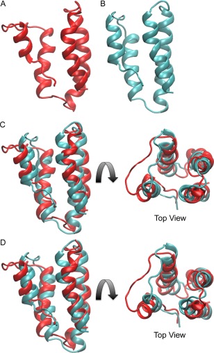
Comparison of the two solution structures of the MLDPMT and MLDRRSP with each other. Shown are representative solution structures of (A) MLDPMT alone in red, (B) MLDRRSP alone in cyan, (C) superimposed with each other with all four helices aligned, and (D) superimposed with each other with helix 3 and 4 aligned.
Helices 3 and 4 can be more closely aligned [Fig. 5(D)], where the backbone RMSD of helix 3 and 4 is 0.84 Å. The differences were primarily observed within the loops and end residues for helices 1 and 2. PMT contains a shorter helix 1 and a longer loop 1 as well as a shorter loop 2, which may account for the differences in the overall position of helix 1 and 2 in the bundle.
The C1 domain of PMT contains the 4‐helix‐bundle motif [Fig. 1(B)], as was previously determined by X‐ray crystallography with a 1.9‐Å resolution (PDB ID: 2EBF).4 Superposition of the representative solution structure of MLDPMT [Fig. 5(A)] with the crystal structure [Fig. 1(B)] showed that helices 3 and 4 are structurally similar [Fig. 6(A)], with a backbone RMSD of 0.75 Å. Helix 1 is in a very different orientation while helix 2 has a slightly different orientation, which may be the result of decreased mobility in the crystal as compared to solution.
Figure 6.
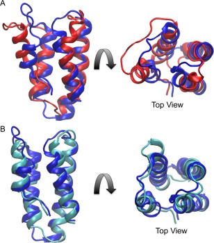
Comparison of the representative solution structures of MLDPMT and MLDRRSP with the corresponding region in the crystal structure C1 domain of PMT. Shown are (A) the superposition of solution MLDPMT (red) and the crystal structure (blue) and (B) the superposition of solution MLDRRSP (cyan) and the crystal structure. Helices 3 and 4 were aligned in each superposition.
Superposition of MLDRRSP [Fig. 5(B)] with the PMT crystal structure likewise showed that the structures are similar, with a backbone RMSD for helices 3 and 4 of 0.43 Å [Fig. 6(B)]. The greatest difference in structure is found in helix 1, where the helix of RRSP is slightly longer than the helix of PMT.
Discussion
Despite the great differences in the origins and functions of PMT and RRSP, both possess a structurally homologous MLD. Both MLDs are 4‐helix‐bundles in solution, confirming the previously predicted secondary structures based on TALOS+ chemical shift calculations.16, 18 These results agree with the corresponding MLDs found in the crystal structures of several clostridial toxins.8, 9, 10, 11 Although there is precedent of the MLDRRSP alone forming a non‐4‐helix‐bundle dimeric structure (PDB ID: 4ERR), we confirm here that MLDRRSP is a 4‐helix‐bundle in solution at ambient temperature.
The structures of MLDPMT and MLDRRSP are in overall agreement with each other. Differences are confined to the orientation of the mobile loops and ends, as well as slight differences in the lengths of the helices. In MLDRRSP, helix 3 is slightly longer and loop 2 is slightly shorter than that of MLDPMT. Furthermore, as indicated by the predicted order parameters (Fig. 3), loop 2 of MLDRRSP is more rigid than loop 2 of MLDPMT. MLDPMT in solution forms a 4‐helix‐bundle similar to that observed in the crystal structure of the C1 domain of full‐length PMT (PDB 2EBF). The lengths and orientations of the helices 2, 3, and 4 are comparable between the structures. However, the orientation of helix 1 and loop 1 exhibit some differences, presumably due to the higher mobility of loop 1 in solution, which could impact the position of helix 1. As mentioned earlier, the loops are mobile and loop 1 in particular is more flexible because it is the longest unrestrained part of the sequence. Likewise, in comparing MLDRRSP [Fig. 4(B)] to the MLD motif in the PMT crystal structure, the structures are fairly similar, except with regard to the length of helix 1, where helix 1 of MLDRRSP in solution is longer than helix 1 in the crystal structure of MLDPMT. The similarity in structure of MLDRRSP to MLDPMT reaffirms the homologous relationship between RRSP and PMT, and by analogy with MLDs of other clostridial glycosylating toxins.
Formation of the 4‐helix‐bundle in solution in the absence of any other domains indicates that the 4‐helix‐bundle conformation is preferred and may be important for localization of the catalytic activity domain to the membrane target site. One possibility is that the 4‐helix‐bundle is required for localizing to the correct membrane associated target,15 presumably through recognition by an as‐yet‐unidentified receptor in the membrane. Alternatively, membrane localization may involve a conformational change of the MLD. In solution, the structures of MLDRRSP and MLDPMT correlate with all other MLD crystal structures previously determined for the full‐length toxins. However, the crystal structure of MLDRRSP (PDB ID: 4ERR) is significantly different. In this crystal structure, the protein appears to form an antiparallel dimer, where the globular 4‐helix‐bundle opens up into a planar structure and the nonpolar faces of helices 1 and 4 of one molecule are interacting with the nonpolar faces of helices 2 and 3 of the other molecule.
This crystal structure may indicate a dimerization process that occurs when binding to the membrane, so that the 4‐helix‐bundle opens into a planar structure exposing the nonpolar faces of the protein and facilitating the nonpolar faces of the protein to embed into the hydrophobic section of the membrane. However, this may also be an artifactual crystal structure of a domain swapped19 structure of MLDRRSP. Without further structural data of the membrane‐bound form of MLD, we are unable to confirm the extended conformation of this putative intermediate, unfolded structure of the MLD. Having now solved the structure of the MLD in solution, we are in a position to study the structure of the membrane‐bound form and determine whether MLDs undergo large conformational changes upon localizing to and interacting with target membranes.
Materials and Methods
Expression and purification of MLDPMT and MLDRRSP
Uniformly 13C,15N‐labeled recombinant MLDPMT and MLDRRSP proteins were expressed and purified from E. coli BL21(DE3) cells (Promega, Fitchburg, WI) grown in medium containing 13C,15N‐BioExpress (Cambridge Isotopes Laboratories, Andover, MA), U‐15N NH4Cl, and U‐13C glucose, as previously described.16
NMR spectroscopy
Solution NMR spectra were collected on a Varian INOVA (600 MHz 1H) spectrometer with a 5‐mm triple resonance (1H–13C–15N) triaxial gradient probe using VnmrJ 2.3 with the BioPack suite (School of Chemical Sciences NMR Facility at the University of Illinois at Urbana‐Champaign).
Spectra of solution state MLDPMT were collected at 30ºC with a 1 mM protein sample in 20 mM bis‐Tris buffer, pH 6.0, containing 100 mM NaCl, 10% D2O (v/v) and 0.01% 4,4‐dimethyl‐4‐silapentane‐1‐sulfonic acid (DSS), as previously described,16 or on a 99% D2O back‐exchanged sample (1 mM in 20 mM bis‐Tris buffer, pH 6.0, containing 100 mM NaCl, 99% D2O, and 0.01% DSS). For MLDRRSP, data was also collected at 30ºC with a 1 mM sample in 20 mM Tris buffer, pH 7.4, containing 500 mM NaCl, 10% D2O, 0.01% DSS, and 2 mM EDTA, as described previously,18 or on a 99% D2O back‐exchanged sample (1 mM sample in 20 mM Tris, pH 7.4, containing 500 mM NaCl, 99% D2O, 0.01% DSS, and 2 mM EDTA). Distance measurements for both proteins were made using 13C‐HSQC‐NOESY spectra with a mixing time of 150 ms and 15N‐HSQC‐NOESY spectra with a mixing time of 150 ms. Spectra were processed with NMRPipe20 and analyzed in Sparky.21
Distance restraints and structure calculation
A total of 200 structures were calculated in XPLOR‐NIH using the NOE distance restraints and dihedral angles (Table 1),22, 23 and the top 20 structures are presented here. The structures of MLDPMT were calculated with 1,485 NOE restraints and 75 dihedral angles [Fig. 3(A)], while those of MLDRRSP were calculated with 1,256 NOE restraints and 73 dihedral angles [Fig. 3(B)]. NOE distance restraints were determined using the PASD algorithm.24, 25 NOESY peaks (data height and peak position) from carbon and nitrogen edited 3D NOESY experiments were imported into the PASD algorithm, where the peaks were categorized into standard distance bins: strong (80%+ intensity): 1.8 Å to 2.7 Å; medium (50% to 80% intensity): 1.8 Å to 3.3 Å; weak (20% to 50% intensity): 1.8 Å to 5.0 Å; very weak (0% to 20% intensity): 1.8 Å to 6.0 Å. Furthermore, the algorithm increases the upper bound of the methyl peak distance ranges by 0.5 Å to compensate for the larger intensities of methyl peaks. Dihedral angles and order parameters were determined using TALOS‐N.17 The chemical shifts used for these calculations were previously published.16, 18
RMSD calculations were made using VMD software for both backbone and heavy atoms for the top 20 structures.26 For comparison of any pair of structures, the RMSD calculations were based on global alignments for the region of interest. Ramachandran analysis was calculated using Molprobity software through the PSVS server to verify angular geometry.27, 28
Data deposition
The ensemble of structures of both proteins was deposited into the Protein Data Bank. The PDB ID for MLDPMT is 2N9V and the PDB ID for MLDRRSP is 2N9W.
Acknowledgments
The authors thank Karla J. F. Satchell and Brett Geissler (Northwestern University Feinberg School of Medicine) for supplying the constructs used in this study and for discussion. The authors also thank Deborah A. Berthold for assistance with sample preparation, Lingyang Zhu for assistance with data collection, and Ming Tang for assistance with structure calculations.
Significance: We have determined the first solution structure of the membrane localization domain (MLD) of Pasteurella multocida toxin and Vibrio vulnificus MARTX toxin. Our results show that these MLDs form a 4‐helix‐bundle similar to that observed in the crystal structure of PMT and several clostridial glycosylating toxins.
References
- 1. Lemichez E, Barbieri JT (2013) General aspects and recent advances on bacterial protein toxins. Cold Spring Harb Perspect Med 3:1–13. [DOI] [PMC free article] [PubMed] [Google Scholar]
- 2. Pullinger GD, Sowdhamini R, Lax AJ (2001) Localization of functional domains of the mitogenic toxin of Pasteurella multocida . Infect Immun 69:7839–7850. [DOI] [PMC free article] [PubMed] [Google Scholar]
- 3. Brothers MC, Ho M, Maharjan R, Clemons NC, Bannai Y, Waites MA, Faulkner MJ, Kuhlenschmidt TB, Kuhlenschmidt MS, Blanke SR, Rienstra CM, Wilson BA (2011) Membrane interaction of Pasteurella multocida toxin involves sphingomyelin. FEBS J 278:4633–4648. [DOI] [PMC free article] [PubMed] [Google Scholar]
- 4. Kitadokoro K, Kamitani S, Miyazawa M, Hanajima‐Ozawa M, Fukui A, Miyake M, Horiguchi Y (2007) Crystal structures reveal a thiol protease‐like catalytic triad in the C‐terminal region of Pasteurella multocida toxin. Proc Natl Acad Sci USA 104:5139–5144. [DOI] [PMC free article] [PubMed] [Google Scholar]
- 5. Aminova LR, Luo SH, Bannai Y, Ho M, Wilson BA (2008) The C3 domain of Pasteurella multocida toxin is the minimal domain responsible for activation of G(q)‐dependent calcium and mitogenic signaling. Protein Sci 17:945–949. [DOI] [PMC free article] [PubMed] [Google Scholar]
- 6. Orth JHC, Preuss I, Fester I, Schlosser A, Wilson BA, Aktories K (2009) Pasteurella multocida toxin activation of heterotrimeric G proteins by deamidation. Proc Natl Acad Sci USA 106:7179–7184. [DOI] [PMC free article] [PubMed] [Google Scholar]
- 7. Kamitani S, Kitadokoro K, Miyazawa M, Toshima H, Fukui A, Abe H, Miyake M, Horiguchi Y (2010) Characterization of the membrane‐targeting C1 domain in Pasteurella multocida toxin. J Biol Chem 285:25467–25475. [DOI] [PMC free article] [PubMed] [Google Scholar]
- 8. Jank T, Ziegler MOP, Schulz GE, Aktories K (2008) Inhibition of the glucosyltransferase activity of clostridial Rho/Ras‐glucosylating toxins by castanospermine. FEBS Lett 582:2277–2282. [DOI] [PubMed] [Google Scholar]
- 9. Reinert DJ, Jank T, Aktories K, Schulz GE (2005) Structural basis for the function of Clostridium difficile toxin B. J Mol Biol 351:973–981. [DOI] [PubMed] [Google Scholar]
- 10. Pruitt RN, Chumbler NM, Rutherford SA, Farrow MA, Friedman DB, Spiller B, Lacy DB (2012) Structural determinants of Clostridium difficile toxin A glucosyltransferase activity. J Biol Chem 287:8013–8020. [DOI] [PMC free article] [PubMed] [Google Scholar]
- 11. Ziegler MOP, Jank T, Aktories K, Schulz GE (2008) Conformational changes and reaction of clostridial glycosylating toxins. J Mol Biol 377:1346–1356. [DOI] [PubMed] [Google Scholar]
- 12. Geissler B, Tungekar R, Satchell KJF (2010) Identification of a conserved membrane localization domain within numerous large bacterial protein toxins. Proc Natl Acad Sci USA 107:5581–5586. [DOI] [PMC free article] [PubMed] [Google Scholar]
- 13. Geissler B, Ahrens S, Satchell KJF (2012) Plasma membrane association of three classes of bacterial toxins is mediated by a basic‐hydrophobic motif. Cell Microbiol 14:286–298. [DOI] [PMC free article] [PubMed] [Google Scholar]
- 14. Antic I, Biancucci M, Satchell KJF (2014) Cytotoxicity of the Vibrio vulnificus MARTX toxin effector DUF5 is linked to the C2A subdomain. Proteins 82:2643–2656. [DOI] [PMC free article] [PubMed] [Google Scholar]
- 15. Antic I, Biancucci M, Zhu YM, Gius DR, Satchell KJF (2015) Site‐specific processing of Ras and Rap1 Switch I by a MARTX toxin effector domain. Nat Commun 6:1–10. [DOI] [PMC free article] [PubMed] [Google Scholar]
- 16. Brothers MC, Geissler B, Hisao GS, Satchell KJF, Wilson BA, Rienstra CM (2014) Backbone and side‐chain resonance assignments of the membrane localization domain from Pasteurella multocida toxin. Biomol NMR Assign 8:221–224. [DOI] [PMC free article] [PubMed] [Google Scholar]
- 17. Shen Y, Bax A (2013) Protein backbone and sidechain torsion angles predicted from NMR chemical shifts using artificial neural networks. J Biomol NMR 56:227–241. [DOI] [PMC free article] [PubMed] [Google Scholar]
- 18. Brothers MC, Geissler B, Hisao GS, Wilson BA, Satchell KJF, Rienstra CM (2014) Backbone and side‐chain assignments of an effector membrane localization domain from Vibrio vulnificus MARTX toxin. Biomol NMR Assign 8:225–228. [DOI] [PMC free article] [PubMed] [Google Scholar]
- 19. Liu Y, Eisenberg D (2002) 3D domain swapping: as domains continue to swap. Protein Sci 11:1285–1299. [DOI] [PMC free article] [PubMed] [Google Scholar]
- 20. Delaglio F, Grzesiek S, Vuister GW, Zhu G, Pfeifer J, Bax A (1995) NMRpipe: a multidimensional spectral processing system based on Unix pipes. J Biomol NMR 6:277–293. [DOI] [PubMed] [Google Scholar]
- 21. Goddard TD (2008) Kneller DG SPARKY 3. San Francisco: University of California. [Google Scholar]
- 22. Schwieters CD, Kuszewski JJ, Tjandra N, Clore GM (2003) The Xplor‐NIH NMR molecular structure determination package. J Magn Reson 160:65–73. [DOI] [PubMed] [Google Scholar]
- 23. Schwieters CD, Kuszewski JJ, Clore GM (2006) Using Xplor‐NIH for NMR molecular structure determination. Prog Nucl Mag Res Sp 48:47–62. [DOI] [PubMed] [Google Scholar]
- 24. Kuszewski J, Schwieters CD, Garrett DS, Byrd RA, Tjandra N, Clore GM (2004) Completely automated, highly error‐tolerant macromolecular structure determination from multidimensional nuclear overhauser enhancement spectra and chemical shift assignments. J Am Chem Soc 126:6258–6273. [DOI] [PubMed] [Google Scholar]
- 25. Kuszewski JJ, Thottungal RA, Clore GM, Schwieters CD (2008) Automated error‐tolerant macromolecular structure determination from multidimensional nuclear overhauser enhancement spectra and chemical shift assignments: improved robustness and performance of the PASD algorithm. J Biomol NMR 41:221–239. [DOI] [PMC free article] [PubMed] [Google Scholar]
- 26. Humphrey W, Dalke A, Schulten K (1996) VMD: visual molecular dynamics. J Mol Graph Model 14:33–38. [DOI] [PubMed] [Google Scholar]
- 27. Lovell SC, Davis IW, Adrendall WB, de Bakker PIW, Word JM, Prisant MG, Richardson JS, Richardson DC (2003) Structure validation by C alpha geometry: phi,psi and C beta deviation. Proteins 50:437–450. [DOI] [PubMed] [Google Scholar]
- 28. Bhattacharya A, Tejero R, Montelione GT (2007) Evaluating protein structures determined by structural genomics consortia. Proteins 66:778–795. [DOI] [PubMed] [Google Scholar]


