Abstract
Phase-resolved OCT and fluorescence microscopy were used simultaneously to examine stereotypic patterns of neural activity in the isolated Drosophila central nervous system. Both imaging modalities were focused on individually identified bursicon neurons known to be involved in a fixed action pattern initiated by ecdysis-triggering hormone. We observed clear correspondence of OCT intensity, phase fluctuations, and activity-dependent calcium-induced fluorescence.
OCIS codes: (110.4500) Optical coherence tomography, (120.5050) Phase measurement, (170.2520) Fluorescence microscopy, (170.2655) Functional monitoring and imaging, (170.4500) Optical coherence tomography
1. Introduction
Current methods for detection of neural activity include functional magnetic resonance imaging [1, 2], intrinsic optical imaging [3, 4], near infrared spectroscopy [5, 6], calcium- [7–9] and voltage-sensitive dyes [10, 11], and a wide variety of electrodes [12–14]. While these technologies have enabled significant scientific and clinical advances, they rely on near or direct contact, chemical or genetic introduction of a fluorescent label, or on secondary signaling (blood oxygenation/flow) in order to detect neural activity. This leaves an unmet need for non-invasive, label-free methods for detection of neural activity.
A range of structural and optical changes are known to accompany action potential propagation, including scattering [15], size [16, 17], birefringence [18], and turbidity [19]. Although these intrinsic changes are of exceedingly small magnitude [20, 21], advances in optical imaging are increasingly making robust detection of such changes possible. A number of studies have investigated the use of optical coherence tomography (OCT) [22], an optical interferometric technique capable of micrometer-level resolution over a sub-surface depth of 1-2 mm in biological tissue. Changes in OCT intensity related to neural activity have been demonstrated in both the retina [23–30] and brain [31–38]. Phase-resolved OCT has also been used to detect transient nanometer-level changes in neuronal thickness during action potential propagation in isolated nerves [39–44].
Optical imaging systems combining both OCT and fluorescence microscopy have been previously demonstrated [45–49]. We have developed a combination imaging system optimized for simultaneous phase-resolved OCT and fluorescence microscopy. In this study, we take advantage of the GAL4/UAS genetic binary system available in fruit fly Drosophila melanogaster to drive expression of the calcium reporters GCaMP-3 or GCaMP-5 in specific ensembles of peptidergic neurons, the kinin and bursicon cells in the pre-pupal central nervous system (CNS). These cells exhibit stereotypic patterns of calcium mobilization upon activation of the G protein-coupled ETH receptor by nanomolar concentrations of ecdysis triggering hormone (ETH), leading to orchestratration of the innate ecdysis behavioral sequence at the end of each molt [50–54]. We correlated changes in OCT intensity and levels of phase fluctuation with calcium-induced fluorescence during the ETH-induced signaling cascade in the fly CNS.
2. Imaging system
Figure 1 shows a schematic diagram of the combined optical coherence tomography and fluorescence microscopy system. The OCT system uses a broadband laser (Femtolasers, Inc., Integral OCT) with a center wavelength of 804 nm and a bandwidth of 170 nm. The sample arm is incorporated into an upright microscope (Olympus BX61W). The OCT beam underfilled the back-aperture of a 20X water-immersion objective (NA = 0.5) by 40% in order to maintain an OCT depth range of at least 500 µm. A galvanometer-based 2-axis optical scanner (Cambridge Technology, Inc., 6210H) is used for raster scanning across the sample. Light reflected back from the reference and sample arms is recombined and collected in the spectrometer. The spectrometer consists of a diffraction grating (Wasatch Photonics, 1200 lpmm, 830 nm), a focusing lens (f = 150 mm), and a line scan camera (Basler sprint camera, sp4096-140 km). Detected spectra are sent to the computer through a frame grabber (National Instrument, NI1429). Another data acquisition card (National Instrument, NI 6259) is used to run two BNC breakout boxes (BNC 2110 and 2120), which generate the control signals for the OCT line scan camera, scanning mirrors, fluorescence stimulation shutter and fluorescence CCD. The sensitivity of the OCT system was determined to be 112 dB, with a depth-dependent sensitivity roll-off of 0.37 dB over 300 µm. For reference, the thickness of a pre-pupal Drosophila CNS is between 75 to 150 µm. Axial and lateral resolutions are 1.72 μm and 4.34 μm, respectively.
Fig. 1.
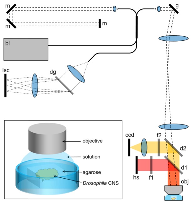
Schematic of the combined fluorescence and OCT imaging system. bl: broadband laser; g: galvo scanners; d1, d2: dichroic filters; f1, f2: wavelength filters; hs: halogen light source; obj: objective; m: mirror; dg: diffraction grating; lsc: line scan camera. Inset: a more detailed illustration of the experimental preparation for phase-resolved measurements.
Light from the excitation light source (Lambda XL, Sutter Instrument) is guided to a stimulation shutter through a liquid light guide. Upon passing through the shutter, incident light passes through an excitation filter (f1) and is combined with OCT light in the microscope via a dichroic mirror (d1, T510lpxrxt, Chroma) and finally is focused on the fly CNS by the objective. Fluorescence emission from the sample is separated from OCT light by another dichroic mirror (d2, 710dcxxr, Chroma), passed through the emission filter (f2), and detected by the CCD camera. The fluorescence system uses a high gain electron multiplier-CCD camera (Hamamatsu C9100-02) for imaging. The signal detected by the fluorescence CCD camera is sent to the computer through a frame grabber (Active Silicon). Filters were chosen for imaging GFP/GCaMP-labeled samples (excitation filter: 488/35 nm, emission filter: 535/50 nm, Chroma Inc). Lateral resolution for the fluorescence system was found to be 1.86 µm with a 20X water immersion objective (N.A. = 0.5).
A multithreaded software program written in Microsoft Visual C++ is used to synchronize all devices during acquisition. All devices are temporally synchronized through a multi-function data acquisition card (NI-6259), which outputs analog waveforms to control the scanning galvos, line triggering of the OCT line scan camera, and a control signal for both the fluorescence CCD camera and stimulation shutter. Group 6, Element 1 of a USAF-1951 target was imaged in order to spatially register the OCT and fluorescence systems (Fig. 2). Lateral scanning was restricted to 150 x 100µm as a visible loss of OCT sensitivity was observed outside of this range. Four common features were identified both in brightfield and OCT en face images to determine transformation parameters (scaling factor and rotation angle) between pixels of the OCT and brightfield images. The resulting close overlap between a red overlay of OCT data with a blue overlay from the fluorescence system shown in Fig. 2 demonstrates spatial registration of the two systems.
Fig. 2.
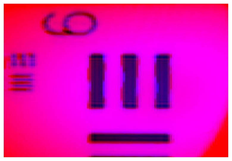
Co-registered images (150 x 100 µm) of a Group 6, Element 1 of a USAF-1951 resolution target acquired from the fluorescence (blue) and OCT (red) imaging systems.
Any ambiguity in phase determination represents a limitation on phase-resolved detection of relative motion. Two fundamental constraints on phase noise are related to the signal-to-noise ratio (SNR) of a measurement [55, 56] and to the ratio of the beam width to the lateral distance between centers of two depth profiles being compared [55]. Contributions from the system to error due to lateral scanning can be largely eliminated through comparison of phases in depth profiles acquired from a single lateral location. Let the acquired SNR and phase be denoted by and , where represents the depth within a single depth profile acquired at time . The smallest meaningful phase difference can then be estimated by the standard deviation of the phase difference between the points, and can be expressed by
| (1) |
A series of measurements from the front and back surfaces of a coverslip with a variable neutral density filter was acquired, and standard deviation of the phase differences was then calculated. A composite value for the SNR from the front and back surfaces was calculated by equating Eq. (1) to the more commonly used expression for phase noise of , which assumes the same SNR between both locations, to instead yield an expression that allows for improved assessment of the mean SNR versus phase for points with different SNR,
| (2) |
A scatterplot of the composite SNR versus the phase noise is shown in Fig. 3, and demonstrates excellent agreement between experimental values and theoretical expectation.
Fig. 3.
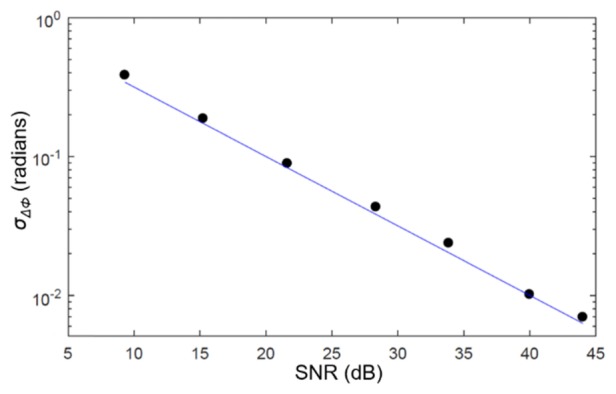
Measurements of the standard deviation of the phase difference between the front and back surfaces of a coverslip at various settings of a neutral density filter. The standard deviations are plotted using the composite SNR expression given in Eq. (2). The line indicates the SNR-limited phase noise floor.
3. Results and discussion
3.1 Changes in intensity
In vitro neuronal imaging was performed on the isolated CNS of pre-pupae (buoyant stage; ~5-6 hr prior to pupal ecdysis). The CNS from genotype Pburs-GAL4; Kinin-GAL4>UAS-GCaMP3 or Kinin-GAL4; Pburs-GAL4>UAS-GCaMP5 is surgically extirpated and embedded in low melting point agarose in a petri dish containing physiological saline. For fluorescence image acquisition, the excitation shutter was kept open for first 160 ms of each image with an exposure time of 1000 ms. Single OCT depth profiles were acquired every 120 µs with an integration time of 100 µs, and sequential volumes comprised of 100 frames of 1024 lines each over a 90 × 90µm lateral area. One OCT volume was acquired every 12 seconds, during which time 10 fluorescence images are acquired (1 fluorescence image every 10 OCT frames). Baseline data was acquired continuously for 5 minutes before addition of ETH to the bath to achieve final concentrations of 150 nM or 600 nM, after which optical data was acquired continuously for 30 minutes. As there was significant lateral scanning involved with volumetric acquisition, only changes in OCT intensity were analyzed in this set of experiments.
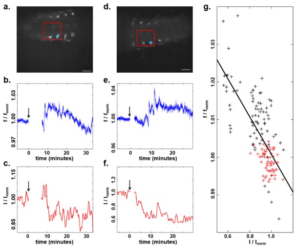
Lateral registration was performed based on maximum correlation of fluorescence images, and lateral shifts at each time point were applied to the corresponding OCT volumes. OCT volumes were then corrected for depth-dependent sensitivity roll-off of the spectrometer. The surface of the volumes was then determined by intensity thresholding, and all data were shifted to align volumes to that surface in order to insure spatial registration of all points over time. Figure 4 shows data from two separate experiments acquired using 150 nM (Fig. 4(a)-4(c)) or 600 nM (Fig. 4(d)-4(f)) ETH. In each case, a bursicon neuron was selected for analysis. Due to the fact that image acquisition had to be reset following ETH presentation, the fluorescence intensity in a small area near the cell of interest before and after ETH presentation was normalized to the first points of each period. The same was done for OCT intensity, which is the averaged OCT SNR of all depth profiles within the same small lateral area over 100 µm of depth beneath the surface of the CNS. The results shown in Fig. 4 demonstrate temporal correlation of changes in both fluorescence and OCT intensity following ETH exposure. This correlation can be quantified through a scatterplot of the normalized OCT versus normalized fluorescence acquired prior to ETH application and for 10 minutes following the first fluorescence peak for both experiments. A linear regression of the data yields an R2 = 0.365 and a p-value < 0.05.
Fig. 4.
(a) Fluorescence image of the Drosophila pre-pupal CNS, with the OCT scanning region marked by the red box and the neuron of interest circled. Scale bar is 100 µm. (b, c) Normalized fluorescence and OCT intensity of the neuron in (a) following exposure of the CNS to 150 nM ETH. The black arrow indicates the starting time of ETH application. (d, e, f) Images and plots from a second experiment following exposure to 600 nM ETH. Gaps correspond to the time required to introduce ETH into the solution and re-focus the imaging system on the sample. (g) Scatterplot of normalized OCT and fluorescence intensities acquired prior to ETH presentation (red) and for 10 minutes following the first fluorescence peak (black) for both experiments.
3.2 Changes in phase
Motion can pose a significant hurdle for phase-resolved measurements. While axial motion can be mitigated by comparing the phase of one depth to that of another depth, lateral movement of even 0.01 times the width of the OCT beam can induce phase noise equivalent to that induced by an average SNR of 30 dB [55]. As this makes minimizing lateral motion between successive phase-resolved depth profiles absolutely critical, phase-resolved measurements on the Drosophila CNS required the additional step of carefully positioning the CNS in low-melting point agarose (see [50] for details), as depicted in the inset of Fig. 1. In order to augment visualization of activity-induced calcium dynamics through agarose, a different strain of Drosophila (Pburs-GAL4;Kinin-GAL4>UAS-GCaMP5) expressing the higher intensity fluorophore GCaMP-5 instead of GCaMP-3 was used for these experiments. Baseline data was acquired for 600 s before addition of ETH to the bath. The presence of agarose necessitated a longer overall acquisition period to account for the much longer diffusion time required for the ETH to reach the CNS, at which point a cascade of activity was observed through fluorescence imaging. OCT acquisition was restricted to a single lateral location at a single bursicon neuron of interest throughout the experiment.
These experiments require positioning the OCT beam over a particular cell body highlighted by fluorescence, and chosen prior to ETH introduction. While the overall position of the CNS embedded in agar remained fixed, it was observed that the individual positions of cell bodies can fluctuate over the course of experiments. However, since the OCT beam remained in a single fixed lateral location, phase-resolved data when the beam was not clearly positioned within the cell cannot be interpreted at this time. The following analysis is based on a particularly stable experiment in which the OCT beam remained clearly within the cell of interest over the entire time period.
Phase analysis was restricted to a depth range spanning 23 points in depth (78.2µm) near the OCT beam focus. In order to mitigate the effect of axial motion caused by variations in the relative path length between the reference and sample arms, phase differences between depths 2 points from each other were calculated according to
| (3) |
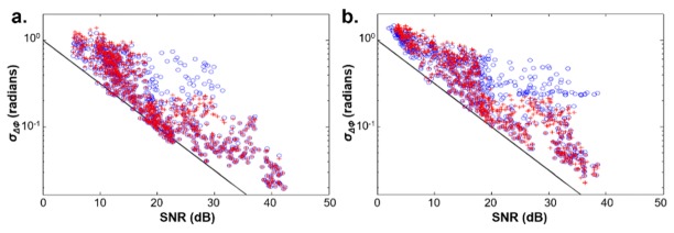
Let the time of the start of exposure for the jth fluorescence images be denoted by . The standard deviation of the resulting phase differences at all 23 points in depth from to were computed. Scatterplots of these standard deviations versus the mean SNR over corresponding periods both before ETH presentation and during fluorescence activity are shown in Fig. 5. Prior to ETH presentation, phase differences are only slightly above those expected for little to no relative motions between depths. During a period of neural activity, we observed an elevation in the standard deviation of the phase differences that can be observed above 18-20 dB. Phase differences for all points with a composite SNR below this threshold were consequently removed from analysis.
Fig. 5.
Scatterplots of the standard deviation of phase differences acquired from Drosophila CNS versus composite SNR before ETH presentation (left) and during the period of neural activity (right) are shown with blue circles. The standard deviations after removal of phase fluctuations are indicated with red crosses.
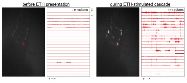
The relationship between fluorescence and the remaining phase-resolved OCT data can be seen in Fig. 6. The position of the OCT beam was fixed on the neuron of interest indicated by the red box in the fluorescence images. Phase difference traces after thresholding correspond to OCT data acquired during acquisition of the fluorescence image. As can be seen in the representative images, little to no phase fluctuation occurs prior to ETH application, but a significant amount of phase fluctuation is evident during a period of neural activity. These phase fluctuations were identified by the following process. Phase trends on a time scale slower than 2.5 ms were removed by subtracting a moving average
| (4) |
where N corresponds to number of points acquired within 2.5ms. A phase fluctuation was identified either when exceeded as defined by Eq. (1) for more than one point in a row or if varied by more than 3 radians within 3 consecutive points. The overlay in Fig. 5 displays the standard deviation of the phase differences after removal of the identified fluctuations. It should be noted that these points hew closer to the theoretical phase noise floor, as would be expected.
Fig. 6.
Fluorescence images (left) and depth-resolved phase difference traces (right, 1 s duration) prior to ETH application and during neural activity. Phase-resolved OCT data was acquired from the neuron indicated with the red circle. (Visualization 1 (11.5MB, AVI) )
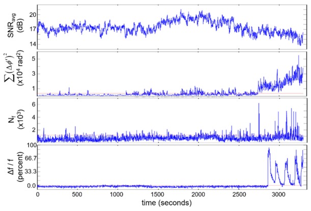
Two different calculations were made to quantify the overall level of phase fluctuations observed in Fig. 7. The first was to take the sum of the square of the phase differences (after the intensity threshold) over all depths, , while the second was to count the number of phase fluctuations . The temporal relationship between these two measures and fluorescence can be seen in Fig. 7, where a clear difference can be noted between the baseline period (0-2500s) and near the time of neuronal calcium dynamics (2700-3400s).
Fig. 7.
Time-resolved plots of the average SNR, summation of the squared phase fluctuations, the number of phase fluctuations, and fluorescence intensity from a neuron. ETH was applied at 600 s.
A few features are worth noting regarding data shown in Fig. 7, primarily the significant relative delay (~150 sec) between onset of phase fluctuation-based measures and GCaMP5-based fluorescence. We hypothesize this is caused by a combination of two factors. First, while calcium mobilization is associated with electrical activity, there is not a one-to-one correspondence between the two; nevertheless this cannot account for a delay of over 2 min. The more important factor is likely to be lateral motion of cell bodies in the fluorescence images. While embedding the CNS in agar removed overall movement of the CNS, we observed lateral movement of fluorescently-labeled cellular features coincident with activity. As even slight amounts of lateral motion can lead to significant changes in phase-resolved OCT, we hypothesize that activity-induced lateral motion of the cell being monitored, potentially by neighboring cells, is a contributor to differences in onset time between phase fluctuation and fluorescence, but posit that these changes are still an effect of neural activity. Future studies will include decoupling contributions to the phase signal of activity-induced lateral motion from activity at the location of interest through motion tracking or phase-resolved detection at a multiplicity of points (with full- or line-field approaches).
4. Conclusion
We developed an optical imaging system capable of simultaneous phase-resolved OCT and fluorescence imaging. This system was used to examine a well-characterized pattern of neural activation in the excised Drosophila CNS. OCT-based measures of intensity and levels of phase fluctuation differ during periods before and during this neural cascade as determined by GCaMP-5 fluorescence measurements of calcium mobilization. As responses of excised but otherwise intact CNS preparations were used, these optical signatures are not coupled to a secondary vascular response. While a one-to-one correspondence between OCT-based and fluorescence signals was not observed, label-free optical measures derived from OCT related to neural activity are evident and are the first demonstration of phase-resolved measurements to directly detect activity in a complex neural structure. Future work will include correlation against electrical detection, use of voltage-dependent indicators, and OCT-based detection at a multiplicity of points to better define OCT signals in relation to fluorescence and electrical activities during a physiologically-evoked neural cascade.
Funding
The authors gratefully acknowledge funding from the California Blueprint for Research to Advance Innovations in Neuroscience (CAL-BRAIN 349329) and the National Institutes of Health (R21 EY026441, U01 EY025501, R00 EB007241).
References and links
- 1.Ogawa S., Lee T. M., Kay A. R., Tank D. W., “Brain magnetic resonance imaging with contrast dependent on blood oxygenation,” Proc. Natl. Acad. Sci. U.S.A. 87(24), 9868–9872 (1990). 10.1073/pnas.87.24.9868 [DOI] [PMC free article] [PubMed] [Google Scholar]
- 2.Moonen C. T., van Zijl P. C., Frank J. A., Le Bihan D., Becker E. D., “Functional magnetic resonance imaging in medicine and physiology,” Science 250(4977), 53–61 (1990). 10.1126/science.2218514 [DOI] [PubMed] [Google Scholar]
- 3.Wang B., Lu Y., Yao X., “In vivo optical coherence tomography of stimulus-evoked intrinsic optical signals in mouse retinas,” J. Biomed. Opt. 21(9), 096010 (2016). 10.1117/1.JBO.21.9.096010 [DOI] [PMC free article] [PubMed] [Google Scholar]
- 4.Chen-Bee C. H., Agoncillo T., Lay C. C., Frostig R. D., “Intrinsic signal optical imaging of brain function using short stimulus delivery intervals,” J. Neurosci. Methods 187(2), 171–182 (2010). 10.1016/j.jneumeth.2010.01.009 [DOI] [PMC free article] [PubMed] [Google Scholar]
- 5.Villringer A., Planck J., Hock C., Schleinkofer L., Dirnagl U., “Near infrared spectroscopy (NIRS): a new tool to study hemodynamic changes during activation of brain function in human adults,” Neurosci. Lett. 154(1-2), 101–104 (1993). 10.1016/0304-3940(93)90181-J [DOI] [PubMed] [Google Scholar]
- 6.Kim S. A., Jun S. B., “In-vivo Optical Measurement of Neural Activity in the Brain,” Exp. Neurobiol. 22(3), 158–166 (2013). 10.5607/en.2013.22.3.158 [DOI] [PMC free article] [PubMed] [Google Scholar]
- 7.Akerboom J., Chen T. W., Wardill T. J., Tian L., Marvin J. S., Mutlu S., Calderón N. C., Esposti F., Borghuis B. G., Sun X. R., Gordus A., Orger M. B., Portugues R., Engert F., Macklin J. J., Filosa A., Aggarwal A., Kerr R. A., Takagi R., Kracun S., Shigetomi E., Khakh B. S., Baier H., Lagnado L., Wang S. S., Bargmann C. I., Kimmel B. E., Jayaraman V., Svoboda K., Kim D. S., Schreiter E. R., Looger L. L., “Optimization of a GCaMP calcium indicator for neural activity imaging,” J. Neurosci. 32(40), 13819–13840 (2012). 10.1523/JNEUROSCI.2601-12.2012 [DOI] [PMC free article] [PubMed] [Google Scholar]
- 8.Lemon W. C., Pulver S. R., Höckendorf B., McDole K., Branson K., Freeman J., Keller P. J., “Whole-central nervous system functional imaging in larval Drosophila,” Nat. Commun. 6, 7924 (2015). 10.1038/ncomms8924 [DOI] [PMC free article] [PubMed] [Google Scholar]
- 9.Chen T. W., Wardill T. J., Sun Y., Pulver S. R., Renninger S. L., Baohan A., Schreiter E. R., Kerr R. A., Orger M. B., Jayaraman V., Looger L. L., Svoboda K., Kim D. S., “Ultrasensitive fluorescent proteins for imaging neuronal activity,” Nature 499(7458), 295–300 (2013). 10.1038/nature12354 [DOI] [PMC free article] [PubMed] [Google Scholar]
- 10.Homma R., Baker B. J., Jin L., Garaschuk O., Konnerth A., Cohen L. B., Zecevic D., “Wide-field and two-photon imaging of brain activity with voltage- and calcium-sensitive dyes,” Philos. Trans. R. Soc. Lond. B Biol. Sci. 364(1529), 2453–2467 (2009). 10.1098/rstb.2009.0084 [DOI] [PMC free article] [PubMed] [Google Scholar]
- 11.Blasdel G. G., Salama G., “Voltage-sensitive dyes reveal a modular organization in monkey striate cortex,” Nature 321(6070), 579–585 (1986). 10.1038/321579a0 [DOI] [PubMed] [Google Scholar]
- 12.Spira M. E., Hai A., “Multi-electrode array technologies for neuroscience and cardiology,” Nat. Nanotechnol. 8(2), 83–94 (2013). 10.1038/nnano.2012.265 [DOI] [PubMed] [Google Scholar]
- 13.Khodagholy D., Gelinas J. N., Thesen T., Doyle W., Devinsky O., Malliaras G. G., Buzsáki G., “NeuroGrid: recording action potentials from the surface of the brain,” Nat. Neurosci. 18(2), 310–315 (2014). 10.1038/nn.3905 [DOI] [PMC free article] [PubMed] [Google Scholar]
- 14.Moore-Kochlacs C., Scholvin J., Kinney J. P., Bernstein J. G., Yoon Y. G., Arfin S. K., Kopell N., Boyden E. S., “Principles of high–fidelity, high–density 3–d neural recording,” BMC Neurosci. 15(1), 1 (2014).24380503 [Google Scholar]
- 15.Hill D. K., Keynes R. D., “Opacity changes in stimulated nerve,” J. Physiol. 108(3), 278–281 (1949). 10.1113/jphysiol.1949.sp004331 [DOI] [PubMed] [Google Scholar]
- 16.Hill B. C., Schubert E. D., Nokes M. A., Michelson R. P., “Laser interferometer measurement of changes in crayfish axon diameter concurrent with action potential,” Science 196(4288), 426–428 (1977). 10.1126/science.850785 [DOI] [PubMed] [Google Scholar]
- 17.Hill D. K., “The volume change resulting from stimulation of a giant nerve fibre,” J. Physiol. 111(3-4), 304–327 (1950). 10.1113/jphysiol.1950.sp004481 [DOI] [PMC free article] [PubMed] [Google Scholar]
- 18.Cohen L. B., Keynes R. D., Hille B., “Light scattering and birefringence changes during nerve activity,” Nature 218(5140), 438–441 (1968). 10.1038/218438a0 [DOI] [PubMed] [Google Scholar]
- 19.Tasaki I., Watanabe A., Sandlin R., Carnay L., “Changes in fluorescence, turbidity, and birefringence associated with nerve excitation,” Proc. Natl. Acad. Sci. U.S.A. 61(3), 883–888 (1968). 10.1073/pnas.61.3.883 [DOI] [PMC free article] [PubMed] [Google Scholar]
- 20.Cohen L. B., Salzberg B. M., Grinvald A., “Optical methods for monitoring neuron activity,” Annu. Rev. Neurosci. 1(1), 171–182 (1978). 10.1146/annurev.ne.01.030178.001131 [DOI] [PubMed] [Google Scholar]
- 21.Cohen L. B., “Changes in neuron structure during action potential propagation and synaptic transmission,” Physiol. Rev. 53(2), 373–418 (1973). [DOI] [PubMed] [Google Scholar]
- 22.Huang D., Swanson E. A., Lin C. P., Schuman J. S., Stinson W. G., Chang W., Hee M. R., Flotte T., Gregory K., Puliafito C. A., et, “Optical coherence tomography,” Science 254(5035), 1178–1181 (1991). 10.1126/science.1957169 [DOI] [PMC free article] [PubMed] [Google Scholar]
- 23.Bizheva K., Pflug R., Hermann B., Považay B., Sattmann H., Qiu P., Anger E., Reitsamer H., Popov S., Taylor J. R., Unterhuber A., Ahnelt P., Drexler W., “Optophysiology: depth-resolved probing of retinal physiology with functional ultrahigh-resolution optical coherence tomography,” Proc. Natl. Acad. Sci. U.S.A. 103(13), 5066–5071 (2006). 10.1073/pnas.0506997103 [DOI] [PMC free article] [PubMed] [Google Scholar]
- 24.Akhlagh Moayed A., Hariri S., Choh V., Bizheva K., “Correlation of visually evoked intrinsic optical signals and electroretinograms recorded from chicken retina with a combined functional optical coherence tomography and electroretinography system,” J. Biomed. Opt. 17(1), 016011 (2012). 10.1117/1.JBO.17.1.016011 [DOI] [PubMed] [Google Scholar]
- 25.Srinivasan V. J., Wojtkowski M., Fujimoto J. G., Duker J. S., “In vivo measurement of retinal physiology with high-speed ultrahigh-resolution optical coherence tomography,” Opt. Lett. 31(15), 2308–2310 (2006). 10.1364/OL.31.002308 [DOI] [PubMed] [Google Scholar]
- 26.Jonnal R. S., Rha J., Zhang Y., Cense B., Gao W., Miller D. T., “In vivo functional imaging of human cone photoreceptors,” Opt. Express 15(24), 16141–16160 (2007). 10.1364/OE.15.016141 [DOI] [PMC free article] [PubMed] [Google Scholar]
- 27.Srinivasan V. J., Chen Y., Duker J. S., Fujimoto J. G., “In vivo functional imaging of intrinsic scattering changes in the human retina with high-speed ultrahigh resolution OCT,” Opt. Express 17(5), 3861–3877 (2009). 10.1364/OE.17.003861 [DOI] [PMC free article] [PubMed] [Google Scholar]
- 28.Hanazono G., Tsunoda K., Shinoda K., Tsubota K., Miyake Y., Tanifuji M., “Intrinsic signal imaging in macaque retina reveals different types of flash-induced light reflectance changes of different origins,” Invest. Ophthalmol. Vis. Sci. 48(6), 2903–2912 (2007). 10.1167/iovs.06-1294 [DOI] [PubMed] [Google Scholar]
- 29.Schmoll T., Kolbitsch C., Leitgeb R. A., “In vivo functional retinal optical coherence tomography,” J. Biomed. Opt. 15(4), 041513 (2010). 10.1117/1.3463008 [DOI] [PubMed] [Google Scholar]
- 30.Moayed A. A., Hariri S., Choh V., Bizheva K., “In vivo imaging of intrinsic optical signals in chicken retina with functional optical coherence tomography,” Opt. Lett. 36(23), 4575–4577 (2011). 10.1364/OL.36.004575 [DOI] [PubMed] [Google Scholar]
- 31.Aguirre A. D., Chen Y., Fujimoto J. G., Ruvinskaya L., Devor A., Boas D. A., “Depth-resolved imaging of functional activation in the rat cerebral cortex using optical coherence tomography,” Opt. Lett. 31(23), 3459–3461 (2006). 10.1364/OL.31.003459 [DOI] [PMC free article] [PubMed] [Google Scholar]
- 32.Rajagopalan U. M., Tanifuji M., “Functional optical coherence tomography reveals localized layer-specific activations in cat primary visual cortex in vivo,” Opt. Lett. 32(17), 2614–2616 (2007). 10.1364/OL.32.002614 [DOI] [PubMed] [Google Scholar]
- 33.Chen Y., Aguirre A. D., Ruvinskaya L., Devor A., Boas D. A., Fujimoto J. G., “Optical coherence tomography (OCT) reveals depth-resolved dynamics during functional brain activation,” J. Neurosci. Methods 178(1), 162–173 (2009). 10.1016/j.jneumeth.2008.11.026 [DOI] [PMC free article] [PubMed] [Google Scholar]
- 34.Graf B. W., Ralston T. S., Ko H.-J., Boppart S. A., “Detecting intrinsic scattering changes correlated to neuron action potentials using optical coherence imaging,” Opt. Express 17(16), 13447–13457 (2009). 10.1364/OE.17.013447 [DOI] [PMC free article] [PubMed] [Google Scholar]
- 35.Eberle M. M., Reynolds C. L., Szu J. I., Wang Y., Hansen A. M., Hsu M. S., Islam M. S., Binder D. K., Park B. H., “In vivo detection of cortical optical changes associated with seizure activity with optical coherence tomography,” Biomed. Opt. Express 3(11), 2700–2706 (2012). 10.1364/BOE.3.002700 [DOI] [PMC free article] [PubMed] [Google Scholar]
- 36.Tsytsarev V., Rao B., Maslov K. I., Li L., Wang L. V., “Photoacoustic and optical coherence tomography of epilepsy with high temporal and spatial resolution and dual optical contrasts,” J. Neurosci. Methods 216(2), 142–145 (2013). 10.1016/j.jneumeth.2013.04.001 [DOI] [PMC free article] [PubMed] [Google Scholar]
- 37.Eberle M. M., Hsu M. S., Rodriguez C. L., Szu J. I., Oliveira M. C., Binder D. K., Park B. H., “Localization of cortical tissue optical changes during seizure activity in vivo with optical coherence tomography,” Biomed. Opt. Express 6(5), 1812–1827 (2015). 10.1364/BOE.6.001812 [DOI] [PMC free article] [PubMed] [Google Scholar]
- 38.Fujimoto, J.G., I. Gorczyńska, J.A. Izatt, J. Wyszkowska, D. Bukowska, V.V. Tuchin, D. Ruminski, K. Karnowski, M. Stankiewicz, and M. Wojtkowski, OCT detection of neural activity in American cockroach nervous system. 8571 85711V (2013).
- 39.Akkin T., Davé D., Milner T., Rylander Iii H., “Detection of neural activity using phase-sensitive optical low-coherence reflectometry,” Opt. Express 12(11), 2377–2386 (2004). 10.1364/OPEX.12.002377 [DOI] [PubMed] [Google Scholar]
- 40.Fang-Yen C., Chu M. C., Seung H. S., Dasari R. R., Feld M. S., “Noncontact measurement of nerve displacement during action potential with a dual-beam low-coherence interferometer,” Opt. Lett. 29(17), 2028–2030 (2004). 10.1364/OL.29.002028 [DOI] [PubMed] [Google Scholar]
- 41.Akkin T., Joo C., de Boer J. F., “Depth-resolved measurement of transient structural changes during action potential propagation,” Biophys. J. 93(4), 1347–1353 (2007). 10.1529/biophysj.106.091298 [DOI] [PMC free article] [PubMed] [Google Scholar]
- 42.Akkin T., Landowne D., Sivaprakasam A., “Optical coherence tomography phase measurement of transient changes in squid giant axons during activity,” J. Membr. Biol. 231(1), 35–46 (2009). 10.1007/s00232-009-9202-4 [DOI] [PubMed] [Google Scholar]
- 43.Yeh Y.-J., Black A. J., Landowne D., Akkin T., “Optical coherence tomography for cross-sectional imaging of neural activity,” Neurophotonics 2(3), 035001 (2015). 10.1117/1.NPh.2.3.035001 [DOI] [PMC free article] [PubMed] [Google Scholar]
- 44.Akkin T., Landowne D., Sivaprakasam A., “Detection of Neural Action Potentials Using Optical Coherence Tomography: Intensity and Phase Measurements with and without Dyes,” Front. Neuroenergetics 2, 22 (2010). [DOI] [PMC free article] [PubMed] [Google Scholar]
- 45.Amaechi B. T., Podoleanu A., Higham S. M., Jackson D. A., “Correlation of quantitative light-induced fluorescence and optical coherence tomography applied for detection and quantification of early dental caries,” J. Biomed. Opt. 8(4), 642–647 (2003). 10.1117/1.1606685 [DOI] [PubMed] [Google Scholar]
- 46.Beaurepaire E., Moreaux L., Amblard F., Mertz J., “Combined scanning optical coherence and two-photon-excited fluorescence microscopy,” Opt. Lett. 24(14), 969–971 (1999). 10.1364/OL.24.000969 [DOI] [PubMed] [Google Scholar]
- 47.Tumlinson A. R., Hariri L. P., Utzinger U., Barton J. K., “Miniature endoscope for simultaneous optical coherence tomography and laser-induced fluorescence measurement,” Appl. Opt. 43(1), 113–121 (2004). 10.1364/AO.43.000113 [DOI] [PubMed] [Google Scholar]
- 48.Lorenser D., Quirk B. C., Auger M., Madore W.-J., Kirk R. W., Godbout N., Sampson D. D., Boudoux C., McLaughlin R. A., “Dual-modality needle probe for combined fluorescence imaging and three-dimensional optical coherence tomography,” Opt. Lett. 38(3), 266–268 (2013). 10.1364/OL.38.000266 [DOI] [PubMed] [Google Scholar]
- 49.Liang S., Saidi A., Jing J., Liu G., Li J., Zhang J., Sun C., Narula J., Chen Z., “Intravascular atherosclerotic imaging with combined fluorescence and optical coherence tomography probe based on a double-clad fiber combiner,” J. Biomed. Opt. 17(7), 070501 (2012). 10.1117/1.JBO.17.7.070501 [DOI] [PMC free article] [PubMed] [Google Scholar]
- 50.Kim Y.-J., Žitňan D., Galizia C. G., Cho K.-H., Adams M. E., “A command chemical triggers an innate behavior by sequential activation of multiple peptidergic ensembles,” Curr. Biol. 16(14), 1395–1407 (2006). 10.1016/j.cub.2006.06.027 [DOI] [PubMed] [Google Scholar]
- 51.Kim Y.-J., Žitňan D., Cho K.-H., Schooley D. A., Mizoguchi A., Adams M. E., “Central peptidergic ensembles associated with organization of an innate behavior,” Proc. Natl. Acad. Sci. U.S.A. 103(38), 14211–14216 (2006). 10.1073/pnas.0603459103 [DOI] [PMC free article] [PubMed] [Google Scholar]
- 52.Žitňan D., Kim Y.-J., Zitnanová I., Roller L., Adams M. E., “Complex steroid-peptide-receptor cascade controls insect ecdysis,” Gen. Comp. Endocrinol. 153(1-3), 88–96 (2007). 10.1016/j.ygcen.2007.04.002 [DOI] [PMC free article] [PubMed] [Google Scholar]
- 53.Roller L., Zitnanová I., Dai L., Šimo L., Park Y., Satake H., Tanaka Y., Adams M. E., Žitňan D., “Ecdysis triggering hormone signaling in arthropods,” Peptides 31(3), 429–441 (2010). 10.1016/j.peptides.2009.11.022 [DOI] [PMC free article] [PubMed] [Google Scholar]
- 54.Kim D.-H., Han M.-R., Lee G., Lee S. S., Kim Y.-J., Adams M. E., “Rescheduling behavioral subunits of a fixed action pattern by genetic manipulation of peptidergic signaling,” PLoS Genet. 11(9), e1005513 (2015). 10.1371/journal.pgen.1005513 [DOI] [PMC free article] [PubMed] [Google Scholar]
- 55.Park B., Pierce M. C., Cense B., Yun S.-H., Mujat M., Tearney G., Bouma B., de Boer J., “Real-time fiber-based multi-functional spectral-domain optical coherence tomography at 1.3 µm,” Opt. Express 13(11), 3931–3944 (2005). 10.1364/OPEX.13.003931 [DOI] [PubMed] [Google Scholar]
- 56.Yazdanfar S., Yang C., Sarunic M., Izatt J., “Frequency estimation precision in Doppler optical coherence tomography using the Cramer-Rao lower bound,” Opt. Express 13(2), 410–416 (2005). 10.1364/OPEX.13.000410 [DOI] [PubMed] [Google Scholar]


