Abstract
Core/shell nanofibers are becoming increasingly popular for applications in tissue engineering. Nanofibers alone provide surface topography and increased surface area that promote cellular attachment; however, core/shell nanofibers provide the versatility of incorporating two materials with different properties into one. Such synthetic materials can provide the mechanical and degradation properties required to make a construct that mimics in vivo tissue. Many variations of these fibers can be produced. The challenge lies in the ability to characterize and quantify these nanofibers post fabrication. We developed a non-invasive method for the composition characterization and quantification at the nanoscale level of fibers using Confocal Raman microscopy. The biodegradable/biocompatible nanofibers, Poly (glycerol-sebacate)/Poly (lactic-co-glycolic) (PGS/PLGA), were characterized as a part of a fiber scaffold to quickly and efficiently analyze the quality of the substrate used for tissue engineering.
OCIS codes: (300.6450) Spectroscopy, Raman; (160.5470) Polymers; (180.5655) Raman microscopy; (160.4236) Nanomaterials
1. Introduction
Nanofibers are made of either synthetic, natural, or a combination of polymeric materials that provide environmental and physical cues supporting the growth and development of tissues [1]. Synthetic polymeric fiber scaffolds deliver a more controllable system than natural materials, both mechanically and chemically. Having the ability to fine-tune nanofiber properties is of great interest for tailoring a scaffold system to a specific application. Electrospinning is a widely used method for producing micro- and nanofibrous scaffolds [2,3]. It involves dissolving a polymeric material in a solvent and subjecting it to an electric field. This strong electrostatic field induces a charge repulsion opposing the liquid droplets’ surface tension [4]. Once the surface tension of the liquid droplet is broken, the polymer-solvent solution is ejected from the formed Taylor cone to the collector plate, where fibers are shaped in a nonwoven mesh [5]. There are many different forms of electrospinning, including single-fluid and dual-fluid electrospinning. However, dual-fluid electrospinning is becoming more common due to its ability to enhance the functionality of resulting fiber scaffolds. Dual-fluid electrospinning involves using a co-axial spinneret and two dissimilar polymer solutions, drawn independently through a capillary, to generate nanofibrous scaffolds. Under certain conditions these fibers can form a core/shell configuration [6].
Core/Shell nanofibers offer improvements in several biological fields, such as drug delivery [7], tissue repair [8], and tissue engineering [9]. For tissue engineering, this method can lead to advances in biocompatibility, biodegradability, hydrophilicity and mechanical properties [10,11]. The positive effects of core/shell fiber configurations are experimentally recognized under various bioassays; however, synthesis is more complex than single-fluid electrospinning. Dual-fluid electrospinning is particularly sensitive to multiple environmental factors, including humidity and temperature, but also to solvent interactions and intermixing, that can lead to blending of core/shell fiber materials [12]. Scaffold material characterization is also an underestimated challenge.
Typical characterization of the core/shell nanofiber structures has been accomplished by means of Transmission Electron Microscopy (TEM) [10–16], Scanning Electron Microscopy (SEM) [17,18] and Atomic Force Microscopy (AFM) [10]. T.T.T. Nguyen et al. demonstrated core/shell characterization of poly (lactic acid) (PLA)/chitosan nanofibers using TEM. Their method was based on utilizing different densities of these materials, which lead to each material transmitting different amounts of electrons. PLA has a higher density than chitosan, which results in PLA having a darker appearance [16]. Characterization of core/shell nanofibers has also been accomplished by SEM. B. Yu et al. produced poly (glycerol sebacate) (PGS)/ poly (L-lactic acid) (PLLA) core/shell nanofibers to fine-tune the mechanical properties of their tissue scaffold. Characterization was performed by micro-sectioning in liquid nitrogen using a cryogenic microtome [17]. Finally, AFM has also been used for characterizing core/shell nanofibers. R. Chen et al. suggested the differences in surface topography with introduction of collagen as the shell, and thermoplastic poly urethane as the core. Using a height mode on the AFM, they were able to resolve the difference in surface roughness of the core/shell fibers, compared to a nanofiber blend of the two materials [10].
Although these methods of fiber characterization are well established in the literature, none of them reveal the actual spatial distribution of the chemical content within the nanofiber scaffolds. Knowing the percentage of each material located in the core and shell can provide an understanding of dual-fluid electrospinning and the morphology changes the fibers undergo with varying electrospinning parameters. One characterization technique that can deliver this type of information for these composite fibers is Confocal Raman microscopy, which combines confocal imaging with Raman spectroscopy. Confocal microscopes, invented by Marvin Minsky [19], are known for clear image quality, 3D mapping capabilities, and elimination of the need for sample processing prior to imaging [19]. Coupled with Raman Spectroscope, it allows the analysis of chemical composition of each pixel of a sample in the XY (lateral) and Z (depth) directions with resolution under 1μm [20]. Confocal Raman microscopy has been used for a number of different imaging research applications, from carbon nanotubes (CNTs) [21] to label-free live cell imaging [22,23], and even characterization of plant cell walls [24,25]. However, characterization of core/shell nanofibers has not yet been explored. In this study, PGS/PLGA core/shell nanofibers, along with PLGA nanofibers as a control, were fabricated and characterized using Raman spectroscopic mapping to analyze their core/shell chemical structure and morphology.
Experimental
2.1. Materials
PLGA 85:15 was purchased from Durect LACTEL (Cupertino, CA), while Hexafluoroisopropanol (HFIP), Glycerol (reagent plus > 99% pure) and Sebacic acid (99% pure) were obtained from Sigma-Aldrich.
Poly (glycerol-sebacate) (PGS) was synthesized following previously used methods [26]. In brief, polymerization took place using the 1:1 ratio; equimolar amounts of glycerol and sebacic acid were placed in a round-bottom flask, where an overnight esterification was carried out at 120°C. Reaction pressure was slowly reduced to 50 mTorr and the reaction continued under vacuum for 24 hours, resulting in PGS pre-polymer that was then used throughout this paper.
2.2. Sample preparation
2.2.2. PGS/PLGA nanofiber parameters
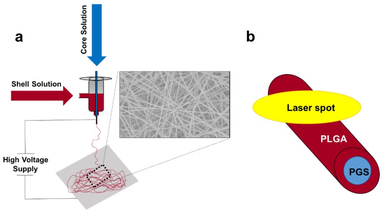
PGS/PLGA nanofibers were prepared using a core/shell coaxial spinneret. PGS pre-polymer was dissolved in HFIP (16% w/w). The PLGA solution consisted of 1% NaCl, 10µL SRB dye, and 85:15 PLGA dissolved in HFIP, making an 8% w/w solution [27–30]. Two independent syringe pumps were used with the two polymeric solutions, connected to the co-axial spinneret by PTFE tubing. The core and shell solution flow rates were varied for this study in order to obtain a homogenous fiber mat and a non-homogenous fiber mat containing PGS-rich beads. The non-homogenous fiber mat, containing what we hypothesized as PGS-rich beads, was obtained with flow rates of 9 µL/min and 1.5 µL/min for the PGS and PLGA solution, respectively (Fig. 1(a)). A homogenous PGS/PLGA fiber mat was obtained with flow rates of 1.5 µL/min and 1.5 µL/min for the PGS and PLGA solution, respectively (Fig. 1(b)). The two solutions did not come in contact until they met at the end of the needle tip, where a 12kV voltage was applied. Samples were spun for 5 seconds on a glass microscope slide wrapped in aluminum foil to create single fibers for Raman analysis. Figure 2 shows the diagram of the electrospinning apparatus, and the expected internal structure of the PGS/PLGA fiber. Fiber diameters were calculated by averaging 100 different fiber diameters calculated from several SEM images and Image J.
Fig. 1.
Scanning electron microscope (SEM) images of fibers used for this study. PGS/PLGA fiber mat with varying flow rates of (a) 9 µl/min / 1.5 µl/min and (b) 1.5 µl/min / 1.5 µl/min, respectively. (c) SEM image of PLGA nanofiber mat. Scale, 2µm. Average fiber diameters for Fig. 1(a), 1(b) and 1(c) were 366 ± 150 nm, 245 ± 60 nm and 166 ± 37 nm, respectively.
Fig. 2.
A diagram of the electrospinning apparatus with SEM image of the fiber mat (a), and the expected internal structure of the fibers, with laser spot from Raman scanning microscope shown to scale (b).
2.2.1. PLGA nanofiber parameters
Using a single-fluid electrospinning setup, 8% PLGA, 10µL SRB dye, and 1% NaCl (w/w) in HFIP were placed in a syringe pump at a flow rate of 3µL/min (Fig. 1(c)). The voltage and the distance of the needle from the collector plate were 10kV and 15m respectively. All samples were electrospun on glass microscope slides wrapped in aluminum foil, and spun on for 5 seconds in order to have single fibers for analysis. Fiber diameters were calculated from several SEM images and Image J by averaging 100 different fibers.
2.2.2 SEM characterization
Both PLGA and PGS/PLGA samples were characterized using a Zeiss 1550 field emission scanning electron microscope (Leo Electron Microscopy Ltd., Cambridge, UK; Carl Zeiss, Jena, Germany). Several images were then analyzed using the Zeiss integrated software and ImageJ to analyze average fiber diameters. Average fiber diameters for Fig. 1(a), 1(b) and 1(c) were 366 ± 150 nm, 245 ± 60 nm and 166 ± 37 nm, respectively.
2.3. Confocal Raman spectroscopy
Raman spectra of PGS and PLGA polymers were measured using LabRAM HR Evolution confocal scanning microscope (HORIBA) with Synapse detector. The excitation wavelength was 473 nm. The diffraction grating of 300 gr/mm was employed together with 50 × microscope objective and a confocal opening of 100 µm. Acquisition time was 5 s times 3 accumulations for all measurements. Spike filter based on multiple accumulations was engaged.
To obtain a pure PGS spectrum, a PGS polymer film was used, since PGS alone does not form a fiber structure. However, a PLGA nanofiber was used to obtain a pure PLGA spectrum, since PLGA film was unusable due to a strong fluorescent signature.
2.4. Confocal Raman mapping and SVD analysis
The spatial distribution measurement of the PGS/PLGA fibers (confocal Raman mapping) was performed using the same LabRAM HR Evolution system that was used for the collection of point spectra. The system settings were the same, except for the acquisition times (2 s times 2 accumulations per point). The confocal scanning was done either across or along the fiber. All spectra were subjected to the polynomial baseline correction routine in LabSpec software (HORIBA). After the baseline correction, the spectral mapping is saved as a table. The table consists of the first row being the wavenumber, its first column being the position of the point in which the spectrum was taken, and its entries with respective Raman intensity detected. This yields the hyperspectral image. Singular Value Decomposition (SVD) analysis allows identification of different chemical regions in the image, and therefore observing the organization of the fiber components. As previously described [31], our SVD based fiber mapping was done using Map Analyzer, an in-home SVD code written in LabVIEW.
3. Results and discussion
3.1. Raman spectra of PLGA nanofibers and PGS films
PGS/PLGA nanofibers were electro spun using a dual-fluid electrospinning setup (Fig. 2(a)). To produce a core/shell fiber, two polymer solutions are independently drawn through a co-axial spinneret capillary, which are then spun to generate nanofibers with a core of one material and the sheath of another. Figure 2(b) shows a schematic of the hypothesized fiber structure. Since the two polymeric solutions were independently drawn through the electrospinning apparatus, varying flow rates for the core and shell solutions were investigated in order to obtain a core/shell configuration. Flow rates of 1.5/1.5 µl/min and 9/1.5 µl/min for the core and shell materials were examined. PLGA nanofibers were produced using a single fluid electrospinning apparatus as a control for all experiments.
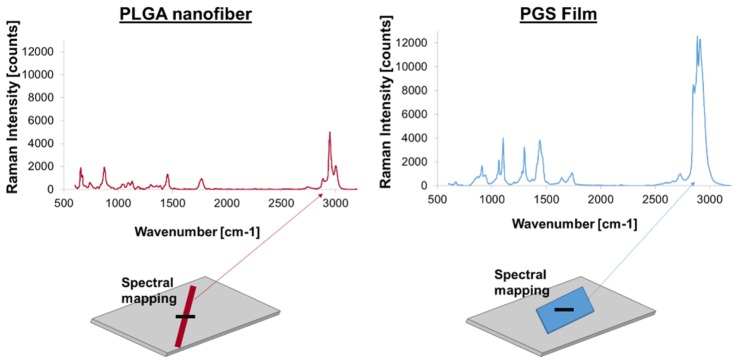
Prior to Raman imaging of the core/shell nanofibers, PLGA single fibers and PGS films were initially used to establish distinct differences in their spectral features. The 473 nm excitation resulted in strong Raman signal from both types of polymer. Of particular advantage was the availability of the CH part of the spectrum (around 3000 cm−1), where both PGS and PLGA components had distinct and prominent spectral features, as can be seen in Fig. 3. The PGS main peak was at 2911 cm−1, while PLGA peaked at 2947 cm−1. Both polymers had additional distinctive features in the 700 – 1700 cm−1 range, but at a much lower intensity (Fig. 3).
Fig. 3.
XY Raman mapping of PLGA nanofiber and PGS film.
3.2. 1D mapping of PLGA and PGS/PLGA nanofibers
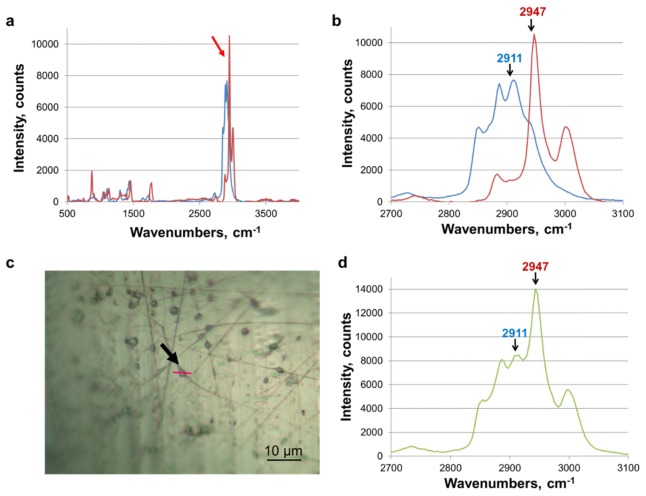
After a distinction between the two polymeric components was identified, Raman spectra of PGS/PLGA nanofibers were collected. Fiber inhomogeneity was observed when electrospinning with higher core flow rates. It was hypothesized that these inconsistencies were due to unstable electrospinning parameters, producing PGS-rich droplets throughout the fiber strands (Fig. 1(a)). Spectral analysis began using this artifact, to investigate whether we can spatially resolve the two different compounds at the sub-micron scale (Fig. 4).
Fig. 4.
Raman reference spectra: (a) Spectra of PLGA nanofiber and PGS film. Arrow indicates the greatest difference between the polymer spectra. Red and blue spectra are PLGA and PGS, respectively. (b) Zoomed in view of distinct polymer peaks. Chosen peaks for PLGA and PGS were 2947 cm−1 and 2911 cm−1 respectively. (c) 50x optical image of PGS/PLGA nanofibers with bubble in the middle. The red line shows where Raman imaging was performed (indicated with an arrow). Scale, 10µm. (d). Spectra obtained from core/shell PLGA/PGS nanofiber bubble structure, demonstrating that both polymers are present in the “bubble” spectrum, with peaks characteristic of PLGA (blue) and PGS (red) indicated with arrows.
Figure 4(a) shows spectra of PLGA nanofiber and PGS film and Fig. 4(b) shows a zoomed in view of distinct polymer peaks. 50x optical image of PGS/PLGA nanofibers with bubble in the middle is shown in Fig. 4(c). Raman mapping was decomposed into pure PGS and PLGA base components via the Classical Least-Squares (CLS) linear regression routine in LabSpec software (HORIBA), demonstrating that both polymers were present in the droplet spectrum, as expected (Fig. 4(d)). In other words, the Raman signal came from both the inner (PGS) and the outer (PLGA) parts of the droplet. It must be noted that the strength of Raman signal is a function of both the amount of material and its Raman cross-section. Therefore, the Raman peak intensity cannot be taken as a measure of the amount of a particular component without correcting for its cross-section first. For example, a stronger PLGA signal in Fig. 4(b) does not necessarily indicate that there is more PLGA material than PGS material in the excitation volume.
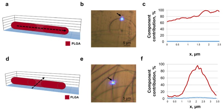
Single PLGA nanofibers were produced to support characterization of PGS/PLGA nanofibers. PLGA nanofibers were analyzed using Raman mapping, both along and across a fiber. Figure 5(a)-5(b) shows a schematic of where the mapping occurred, as well as an optical image during spectral scanning. This spectral mapping was taken along a single PLGA nanofiber. The CLS plot shows no trace of the PGS spectra (Fig. 5(c)). The gradual increase in the component contribution of PLGA is due to the scan slowly getting closer to the center of the fiber (which is slightly curved and not exactly aligned along the scan axis, as seen in Fig. 5(b)). Figures 5(d)-5(e) shows a spectral mapping experiment being taken across a single PLGA nanofiber. As expected, no significant traces of the PGS component were observed while scanning across the nanofiber (Fig. 5(f)).
Fig. 5.
Raman spectra from PLGA nanofiber. (a) Schematic of PLGA fiber cross-section. Raman mapping was performed along the dashed arrow. (b) Optical image showing sample surface mapping recorded parallel to the fiber (indicated with an arrow). Image taken with 50x objective. The red line indicates the location of Raman scan. Scale, 5 µm. (c) Lateral profile confocal Raman scan showing polymer component contribution through the nanofiber. PLGA (red) and PGS (blue). (d) Schematic of PLGA fiber cross-section. Dashed arrow indicates where Raman mapping was performed. (e) Optical image showing sample surface mapping recorded perpendicular to the fiber (indicated with an arrow). Image taken with 50x objective. The red line indicates the location of Raman scan. Scale, 5µm. (f) Confocal Raman scan across the fiber showing polymer component contribution through the nanofiber. PLGA (red) and PGS (blue).
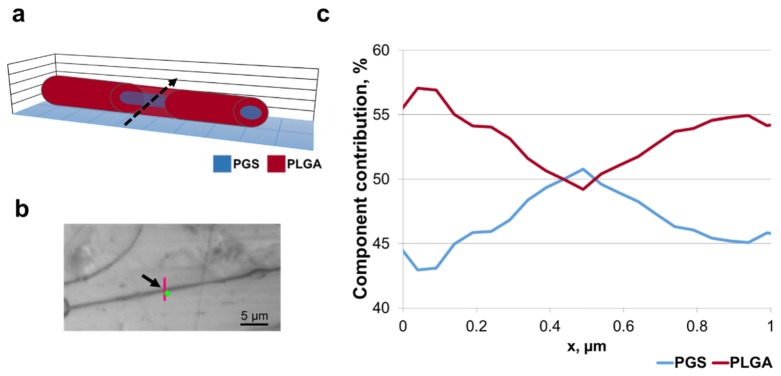
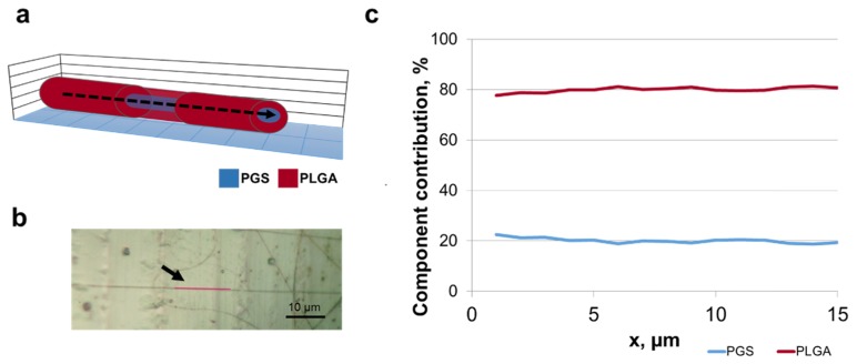
To confirm the core/shell structure of the PGS/PLGA nanofibers, spectroscopic Raman mapping across a fiber was performed on multiple samples. It was expected that the signal from the fiber center would be a mixture of PGS and PLGA spectral signatures, while at the fiber edges only the shell material PLGA would be present. The results are shown in Fig. 6. These results are typical of 12 fibers characterized. Figure 6(a) shows a schematic of the Raman mapping occurring across the fiber. Figure 6(b) is the conventional microscope image of the PGS/PLGA fiber scan area, where the mapped line is shown in red. Figure 6(c) is the result of CLS fitting of the scan spectra, indicating that the distribution of the base components, PGS and PLGA, varied along the fiber cross-section. The peak of PGS component in the CLS plot signifies that there is more PGS in the center of the fiber than at the edges, therefore its relative contribution is higher. The reason for the non-zero PGS contribution at the edges of the scan is the large size of the laser beam spot, compared to the fiber thickness (see Fig. 2(b)). Even when the beam is positioned at the fiber edge, some part of the excitation volume still contains core material. To extract the fiber core and shell size information from these maps, SVD analysis was performed on the hyperspectral data (see section 3.3). Following a scan across a fiber, a scan along the PGS/PLGA nanofiber was performed. Figure 7(a) shows a schematic of the Raman mapping occurring along the fiber, and 7b is an optical image of a single PGS/PLGA nanofiber, where the scanned points are given in red. The CLS fit of the scan (Fig. 7(c)) shows no significant variation in the distribution of the base components, PLGA and PGS, indicating that this fiber is uniform in the axial direction.
Fig. 6.
Raman spectra from core/shell nanofiber cross section. (a) Schematic of fiber cross-section. Raman mapping was done perpendicular to nanofiber (indicated with a dashed arrow). (b) Optical image showing sample surface mapping recorded perpendicular to fiber (indicated with an arrow). Image taken with 50x objective. Scale, 5µm. (c) Confocal Raman scan across the fiber showing polymer component contribution through a nanofiber (only the part of the scan crossing the fiber is shown; the sum of PLGA and PGS components is normalized to 100%). PLGA (red) and PGS (blue).
Fig. 7.
Raman spectra from core/shell nanofiber lateral section. (a) Schematic of fiber cross-section. Raman mapping was parallel to nanofiber (indicated with a dashed arrow). (b) Optical image showing sample surface mapping parallel to a fiber (indicated with an arrow). Image taken with 50x objective. Scale, 10 µm. (c) Lateral profile confocal Raman scan showing polymer component contribution through a nanofiber (the sum of PLGA and PGS components is normalized to 100%). PLGA (red) and PGS (blue).
3.3. SVD analysis
In order to process this hyperspectral data set, we applied Singular Value Decomposition (SVD) analysis to the line scans across the fiber. SVD is a well-known method of partitioning the spectra from a hyperspectral data set into distinct groups, based on the major contributing spectral line shapes (SVD components) [31,32]. The method works as follows: each spectrum collected from a line scan across the fiber is plotted as a single point on an SVD scatter plot (i.e. magnitude of one SVD component versus another). This two dimensional plot is a projection of multi-dimensional space on the basis of the two leading SVD components. Since the fiber contains two polymers, each of the two leading SVD components usually resembles the actual spectrum of either PLGA or PGS. The position of each point on the SVD scatter plot depends on whether the particular spectrum contains contributions from PLGA, PGS, or both. Therefore, the points naturally group together depending on their chemical composition, making it possible to classify image regions based on their chemical identity. Once the pixels have been assigned to groups (this is the only processing step that needs user input), the processing algorithm pseudo-colors the original image accordingly, to create a chemical map of the sample (Fig. 8).
Fig. 8.
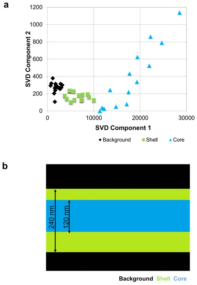
Raman spectroscopic imaging of a nanofiber cross-section by Singular Value Decomposition (SVD): (a) SVD scatter plot, showing clear separation of core and shell spectra (b); 1-D hyperspectral Raman image of the structure of the fiber based on the SVD analysis. Blue indicates core material, green indicates shell material, and black indicates no chemical signature of either polymer.
Figure 8(a) shows the SVD scatter plot obtained from a core/shell fiber, where three distinct groups of spectra, which correspond to the core, shell, and image background, are visible. By examining the shapes of individual components, it was found that SVD components 1 and 2 closely resembled PLGA and PGS spectra respectively. As expected, the signal from the center of the fiber included contributions from both the core and the shell, which lies above and below the core. Consequently, Fig. 8(a) shows the contribution from both SVD components for the core area. The signal from the edges of the fiber shows contributions from PLGA only, and the signal from the points off the fiber has minute contributions of either SVD component. One should note that since this method automatically extracts the line shapes of SVD components, it does not require the knowledge of PLGA and PGS spectra. However, the SVD components 1 and 2 do not mimic the PLGA and PGS spectra exactly, which explains the slight angle between the axis of the plot and PLGA- and PGS-based spectral points in Fig. 8(a).
Once the spectra have been classified, the assigned groups are mapped back onto the one-dimensional scan line (Fig. 8(b)) to identify regions of different chemical composition within the sample. Using this method, the thickness of PLGA shell/PGS core can be evaluated. It is impossible to resolve the features of the fiber directly due to the diffraction limit of the scanning laser spot size. Moreover, as the laser spot is scanned across the fiber, the signal from the shell region will be detectable when the laser spot is only partially overlapping with the fiber, i.e. the thicknesses of the regions will appear wider by the size of the laser spot (~500 nm) on each side of the fiber. However, it is possible to estimate the thickness of the core by knowing the distribution of core and shell regions from SVD, and overall thickness of the fiber from SEM measurements. Figure 8(b) shows that the diameter of the core is 50% of the thickness of the fiber (about 240 nm), so it is approximately 120 nm. Furthermore, for this sample, the distribution of the core material is shown to be slightly offset from the center of the fiber (Fig. 8(b)). This can be due to the core needle being offset in the dual-fluid electrospinning apparatus, or an experimental artifact, such as incorrect SVD mapping or the fiber moving during the scan. Nonetheless, a distinct Raman signal signature was detected for the core component, and another Raman signal signature for the shell component.
4. Conclusion
We have employed Raman spectroscopic mapping to study the structure of polymer nanofibers used for synthetic scaffolds in tissue engineering applications. We were able to confirm the core/shell structure of the PGS/PLGA nanofibers via direct observation of Raman signatures, associating each individual polymer and their distribution in the mixture with different spectra. We have also performed the detailed analysis of nanofiber structure by applying the SVD algorithm, which allowed the automated detection of core and shell distribution within the fiber.
Funding
This work was supported by the University at Albany, SUNY, NIH R01DE022467 (to M.L. and J.C.), NIH C06 RR015464 (to University at Albany, SUNY), and NSF DV10922830 (to J.C.).
References and links
- 1.Liu H., “Electrospining of nanofibers for tissue engineering applications,” J. Nanomater. 2013, 1–31 (2013). 10.1155/2013/365947 [DOI] [Google Scholar]
- 2.Bhardwaj N., Kundu S. C., “Electrospinning: a fascinating fiber fabrication technique,” Biotechnol. Adv. 28(3), 325–347 (2010). 10.1016/j.biotechadv.2010.01.004 [DOI] [PubMed] [Google Scholar]
- 3.Huang Z. M., Zhang Y. Z., Kotaki M., Ramakrishna S., “A review on polymer nanofibers by electrospinning and their applications in nanocomposites,” Compos. Sci. Technol. 63(15), 2223–2253 (2003). 10.1016/S0266-3538(03)00178-7 [DOI] [Google Scholar]
- 4.Haider A., Haider S., Kang I. K., “A comprehensive review summarizing the effect of electrospinning parameters and potential applications of nanofibers in biomedical and biotechnology,” Arab. J. Chem. 11, 15 (2015). 10.1016/j.arabjc.2015.11.015 [DOI] [Google Scholar]
- 5.J. Doshi and D. H. Reneker, “Electrospinning process and applications of electrospun fibers,” Conf. Rec. 1993 IEEE Ind. Appl. Conf. Twenty-Eighth IAS Annu. Meet. 35, 151–160 (1993). 10.1109/IAS.1993.299067 [DOI] [Google Scholar]
- 6.Elahi F., Lu W., Guoping G., Khan F., “Core-shell Fibers for Biomedical Applications-A Review,” Bioeng. Biomed. Sci. J. 3(01), 1–14 (2013). 10.4172/2155-9538.1000121 [DOI] [Google Scholar]
- 7.Chourpa I., Douziech-eyrolles L., Ngaboni-okassa L., Cohen-jonathan S., Souce M., “Molecular composition of iron oxide nanoparticles, precursors for magnetic drug targeting, as characterized by confocal Raman microspectroscopy,” Analyst 130, 1395–1403 (2005). [DOI] [PubMed] [Google Scholar]
- 8.Zhu L., Liu X., Du L., Jin Y., “Preparation of asiaticoside-loaded coaxially electrospinning nanofibers and their effect on deep partial-thickness burn injury,” Biomed. Pharmacother. 83, 33–40 (2016). 10.1016/j.biopha.2016.06.016 [DOI] [PubMed] [Google Scholar]
- 9.Ramakrishna S., Fujihara K., Teo W., Yong T., Ma Z., Ramaseshan R., “Electrospun nanofibers: solving global issues,” Mater. Today 9(3), 40–50 (2006). 10.1016/S1369-7021(06)71389-X [DOI] [Google Scholar]
- 10.Chen R., Huang C., Ke Q., He C., Wang H., Mo X., “Preparation and characterization of coaxial electrospun thermoplastic polyurethane/collagen compound nanofibers for tissue engineering applications,” Colloids Surf. B Biointerfaces 79(2), 315–325 (2010). 10.1016/j.colsurfb.2010.03.043 [DOI] [PubMed] [Google Scholar]
- 11.Zhang Y., Huang Z., Xu X., Lim C. T., Ramakrishna S., “Preparation of Core - Shell Structured PCL- r-Gelatin Bi-Component Nanofibers by coaxial elctrospinning,” Chem. Mater. 16, 3406–3409 (2004). [Google Scholar]
- 12.Ning Wanga K. B., “Electrospun Polyurethane-Core and Gelatin-Shell Coaxial Fibre Coatings for Miniature Implantable Biosensors,” Biofabrication 6, 1–30 (2011). [DOI] [PMC free article] [PubMed] [Google Scholar]
- 13.Pakravan M., Heuzey M. C., Ajji A., “Core-shell structured PEO-chitosan nanofibers by coaxial electrospinning,” Biomacromolecules 13(2), 412–421 (2012). 10.1021/bm201444v [DOI] [PubMed] [Google Scholar]
- 14.Zhang Y. Z., Venugopal J., Huang Z. M., Lim C. T., Ramakrishna S., “Characterization of the surface biocompatibility of the electrospun PCL-collagen nanofibers using fibroblasts,” Biomacromolecules 6(5), 2583–2589 (2005). 10.1021/bm050314k [DOI] [PubMed] [Google Scholar]
- 15.Zhang Y. Z., Wang X., Feng Y., Li J., Lim C. T., Ramakrishna S., “Coaxial electrospinning of (fluorescein isothiocyanate-conjugated bovine serum albumin)-encapsulated poly(ε-caprolactone) nanofibers for sustained release,” Biomacromolecules 7(4), 1049–1057 (2006). 10.1021/bm050743i [DOI] [PubMed] [Google Scholar]
- 16.Nguyen T. T. T., Chung O. H., Park J. S., “Coaxial electrospun poly(lactic acid)/chitosan (core/shell) composite nanofibers and their antibacterial activity,” Carbohydr. Polym. 86(4), 1799–1806 (2011). 10.1016/j.carbpol.2011.07.014 [DOI] [Google Scholar]
- 17.Xu B., Li Y., Fang X., Thouas G. A., Cook W. D., Newgreen D. F., Chen Q., “Mechanically tissue-like elastomeric polymers and their potential as a vehicle to deliver functional cardiomyocytes,” J. Mech. Behav. Biomed. Mater. 28, 354–365 (2013). 10.1016/j.jmbbm.2013.06.005 [DOI] [PubMed] [Google Scholar]
- 18.Wang C., Yan K. W., Lin Y. D., Hsieh P. C. H., “Biodegradable core/shell fibers by coaxial electrospinning: Processing, fiber characterization, and its application in sustained drug release,” Macromolecules 43(15), 6389–6397 (2010). 10.1021/ma100423x [DOI] [Google Scholar]
- 19.Minsky M., “Memoir on inventing the confocal scanning microscope,” Scanning 10(4), 128–138 (1988). 10.1002/sca.4950100403 [DOI] [Google Scholar]
- 20.Lutz A., De Graeve I., Terryn H., “Non-destructive 3-dimensional mapping of microcapsules in polymeric coatings by confocal Raman spectroscopy,” Prog. Org. Coat. 88, 32–38 (2015). 10.1016/j.porgcoat.2015.06.009 [DOI] [Google Scholar]
- 21.Hennrich F., Krupke R., Lebedkin S., Arnold K., Fischer R., Resasco D. E., Kappes M. M., “Raman spectroscopy of individual single-walled carbon nanotubes from various sources,” J. Phys. Chem. B 109(21), 10567–10573 (2005). 10.1021/jp0441745 [DOI] [PubMed] [Google Scholar]
- 22.Caspers P. J., Lucassen G. W., Puppels G. J., “Combined in vivo confocal Raman spectroscopy and confocal microscopy of human skin,” Biophys. J. 85(1), 572–580 (2003). 10.1016/S0006-3495(03)74501-9 [DOI] [PMC free article] [PubMed] [Google Scholar]
- 23.Klein K., Gigler A. M., Aschenbrenner T., Monetti R., Bunk W., Jamitzky F., Morfill G., Stark R. W., Schlegel J., “Label-free live-cell imaging with confocal Raman microscopy,” Biophys. J. 102(2), 360–368 (2012). 10.1016/j.bpj.2011.12.027 [DOI] [PMC free article] [PubMed] [Google Scholar]
- 24.Gierlinger N., Keplinger T., Harrington M., “Imaging of plant cell walls by confocal Raman microscopy,” Nat. Protoc. 7(9), 1694–1708 (2012). 10.1038/nprot.2012.092 [DOI] [PubMed] [Google Scholar]
- 25.N. Gierlinger and and M. Schwanninger , “Chemical Imaging of PoplarWood CellWalls by Confocal Raman Microscopy,” Society 140, 1246–1254 (2010). [DOI] [PMC free article] [PubMed] [Google Scholar]
- 26.Wang Y., Ameer G. A., Sheppard B. J., Langer R., “A tough biodegradable elastomer,” Nat. Biotechnol. 20(6), 602–606 (2002). 10.1038/nbt0602-602 [DOI] [PubMed] [Google Scholar]
- 27.Soscia D. A., Sequeira S. J., Schramm R. A., Jayarathanam K., Cantara S. I., Larsen M., Castracane J., “Salivary gland cell differentiation and organization on micropatterned PLGA nanofiber craters,” Biomaterials 34(28), 6773–6784 (2013). 10.1016/j.biomaterials.2013.05.061 [DOI] [PMC free article] [PubMed] [Google Scholar]
- 28.Cantara S. I., Soscia D. A., Sequeira S. J., Jean-Gilles R. P., Castracane J., Larsen M., “Selective functionalization of nanofiber scaffolds to regulate salivary gland epithelial cell proliferation and polarity,” Biomaterials 33(33), 8372–8382 (2012). 10.1016/j.biomaterials.2012.08.021 [DOI] [PMC free article] [PubMed] [Google Scholar]
- 29.Sequeira S. J., Soscia D. A., Oztan B., Mosier A. P., Jean-Gilles R., Gadre A., Cady N. C., Yener B., Castracane J., Larsen M., “The regulation of focal adhesion complex formation and salivary gland epithelial cell organization by nanofibrous PLGA scaffolds,” Biomaterials 33(11), 3175–3186 (2012). 10.1016/j.biomaterials.2012.01.010 [DOI] [PMC free article] [PubMed] [Google Scholar]
- 30.Sfakis L., Kamaldinov T., Larsen M., Castracane J., Khmaladze A., “Quantification of Confocal images using LabVIEW for tissue engineering applications,” Tissue Eng. Part C Methods 22(11), 1028–1037 (2016). 10.1089/ten.tec.2016.0228 [DOI] [PMC free article] [PubMed] [Google Scholar]
- 31.Khmaladze A., Jasensky J., Price E., Zhang C., Boughton A., Han X., Seeley E., Liu X., Banaszak Holl M. M., Chen Z., “Hyperspectral imaging and characterization of live cells by broadband coherent anti-Stokes Raman scattering (CARS) microscopy with singular value decomposition (SVD) analysis,” Appl. Spectrosc. 68(10), 1116–1122 (2014). 10.1366/13-07183 [DOI] [PubMed] [Google Scholar]
- 32.L. Sfakis, F. Xavier, D. Tuschel, A. Sharikova, M. Larsen, J. Castracane and A. Khmaladze, “Core / Shell Nanofiber Characterization by Raman Scanning Microscopy,” in Latin America Optics & Photonics Conference (LAOP), (Optical Society of America, 2016), paper LTu5A.5. [Google Scholar]


