

Abstract
Noise-induced hearing loss is the second most pervasive disease in the mining industry. The exposure of miners to noise levels above the permissible exposure level results in hearing loss of approximately 80% of coal miners by retirement age. In addition, between 2002 and 2011, approximately 48% of longwall shearer operators were overexposed in coal mines in the United States. Previous research identified the two rotating cutting drums used by the longwall shearer to extract coal as the most significant sound-radiating components. In this context, the National Institute for Occupational Safety and Health conducted research to develop noise controls for longwall mining systems. To this end, structural and acoustic numerical models of a single cutting drum were developed to assess its dynamic and acoustic response, respectively. Once validated, these models were used to explore various noise control concepts including force isolation, varying structural damping and varying component stiffness. Upon multiple simulations, it was determined that structural modifications to increase the stiffness of the outer vane plates were the most practical and durable approach to reduce the sound radiated by the cutting drums. Furthermore, these modifications did not adversely affect the cutting performance, nor the loading ability of the drums. As a result, these structural modifications were implemented into an actual set of drums for evaluation purposes. Results from the underground evaluation, when the modified cutting drums were used under normal operation conditions, showed noise reduction across the entire frequency spectrum with an overall noise reduction of 3 dB in the sound pressure level at the operator location, confirming the validity of the developed noise controls.
1 INTRODUCTION
Noise-induced hearing loss (NIHL) continues to be a prevalent disease in the mining industry. According to a study conducted by the National Institute for Occupational Safety and Health (NIOSH) on the hearing difficulty attributable to employment and occupation, out of 40 industry categories, workers in the mining industry displayed the second largest prevalence of hearing difficulty in the United States from 1997 to 20031. Particularly in the case of underground coal mining, the presence of powerful equipment in confined spaces and in close proximity to the operators results in noise exposures for miners that frequently exceed the permissible exposure level (PEL). An analysis of over 20,000 audiograms from 3,449 coal miners carried out by NIOSH, showed that by age 64, approximately 80% of miners have from moderate to profound high-frequency hearing loss, in contrast to approximately 10% of workers in other industries that were not overexposed to occupational noise2. Furthermore, noise exposure samples collected from longwall shearer operators by the Mine Safety and Health Administration (MSHA) between 2002 and 2011, revealed that approximately 48% of these operators were exposed to noise levels exceeding that agency’s PEL3.
To address the NIHL problem experienced by longwall operators, the Office of Mine Safety and Health Research (OMSHR) of NIOSH conducted research to develop engineering noise controls for longwall mining systems. These systems are sets of machines that work in full synchrony to extract coal from underground mines. Figure 1 shows a simple representation of a typical longwall mining system consisting of the shearer, an armored face conveyor (AFC), a stageloader and the longwall shields. The shearer is equipped with two rotating cutting drums and moves back and forth along the coal face, ripping coal and pushing it to the AFC. The AFC transports the ripped coal to the stageloader. The stageloader crushes the coal and loads it onto a belt conveyor which carries the crushed coal to the surface. Throughout this process, the powered self-advancing longwall shields move forward to provide continuous temporary roof support for the operator, the shearer and the AFC as they advance. The operator location depicted in Fig. 1 represents that used for all field evaluations of noise at the operator location described further in this paper.
Fig. 1.

Schematic representation of a longwall mining system.
Previous research conducted by the United States Bureau of Mines (USBM) identified the cutting drums as the most significant sound-radiating components on a longwall shearer4. The longwall shearer cutting drums examined in the current study consist of a cylindrical shell with a 0.987-meter (38.86-in) outside diameter, a 1.067-meter (42.00-in) height and a 0.05-meter (2.00-in) thick wall, around which four helical vanes are welded as shown in Fig. 2. There are 44 pairs of bit holders and cutting bits welded around the cutting drum, with 7 on the outermost edge of each vane, 12 on the outermost edge of the face ring and 4 on the flange of the face ring. Acoustic measurements conducted at a collaborating mine that uses these particular cutting drums revealed that most of the sound reaching the operator location has a frequency content between 100 and 2,000 Hz, and therefore, this was the frequency range for this study. Considering the geometric complexity and dimensions of these cutting drums, this study developed numerical models of a single cutting drum to explore various noise control concepts. These concepts included: 1) bit isolation, 2) addition of structural damping and 3) structural modifications to increase the stiffness of the dominant sound-radiating components. The excitation forces used to evaluate the various noise control concepts are the forces that arise from the interaction of the cutting bits with the coal and were measured experimentally using an instrumented bit developed during the course of this research. From various simulation analyses, it was determined that a set of structural modifications provides the best noise reduction, durability and ease of implementation. Furthermore, these modifications did not adversely affect the cutting performance, nor the loading ability of the drums. As a result, these structural modifications were implemented into an actual set of drums for evaluation purposes.
Fig. 2.

Drawing of a longwall cutting drum showing its various components.
This paper presents a summary of the various steps taken during the process used to develop noise controls for the cutting drums as well as the results obtained with these controls in terms of noise reduction in laboratory and underground tests. Since the design and dimensions of the cutting drums vary from mine to mine, the intent of this paper is to provide guidelines to develop noise controls for different types of cutting drums.
2 NUMERICAL MODELS OF THE CUTTING DRUM
2.1 Structural Model
A finite element (FE) model of the cutting drum was developed using ANSYS to predict its dynamic behavior. The main body of the cutting drum was modeled as a single body and the welds were represented by overlapping triangular bodies with coincident nodes at their interfaces. The welds between the cylindrical body and the four vanes were grouped together because they have similar geometry and dimensions. Those welds were expected to have more effect on the low-frequency results, because they act like the boundary conditions of the vanes. All of the other welds on the vanes and cylindrical body were categorized as another group because these welds were expected to affect the high-frequency noise radiation more than the first group of welds. Most of the welds were modeled with triangular cross sections.
For modeling purposes, the force excitation was applied at the tips of the cutting bits in order to simulate the real coal cutting force. In this study, the force was exerted on only one of the cutting bits, which is sufficient to reveal the features of the radiated noise. For purposes of symmetry, a second cutting bit was added to the model 180 degrees away from the bit to which forces were applied. All bit holder structures were included in the FE model for the computation of the mode shapes. Only the cutting bits – that are not a part of the cutting drum – were not included in the analysis. The bit is small and rigid in the frequency range used in this study and the mass of the bit, i.e.1 kg (2.2 lb), is very small as compared with the mass of the whole cutting drum, i.e., more than 4,500 kg (9,920 lb). The small mass of the bit only affects the local vibrational deformation and the effect is minor. Therefore, as long as there is no excitation applied to any of the other 42 bits, excluding them does not sacrifice the accuracy of the structural FE model but reduces significantly the degrees of freedom and thus the computational effort.
Using this FE model, a modal analysis was conducted to determine the modal characteristics of the drum, i.e. natural frequencies and mode shapes5. Figure 3 shows the first 12 structural modes. Note that as seen from the discharge side, the drum presents a 2-fold symmetry; that is, the first and the third vanes are symmetric, whereas the second and the fourth vanes – which are slightly different from the first and the third vanes – are also symmetric. As a result, there are various symmetric modes with close natural frequencies. For example, the first and the second modes, the third and the fourth modes and the seventh and eighth modes are symmetric. These results also show that the discharge side of the drum undergoes larger deformations as compared to the face side of the drum due to the added rigidity provided by the face ring.
Fig. 3.

Modal FEA results for the first 12 structural modes.
After the numerical modal analysis was conducted, the results were validated using the results obtained from an experimental modal analysis test (EMA) conducted on an actual cutting drum. For the mode shape correlation, the Modal Assurance Criterion (MAC) value – which measures the degree of correlation between two vectors (mode shapes) – was computed for each mode shape pair. Table 1 lists these values for the first 44 modes. From this table, it can be seen that a high degree of correlation, i.e. above 90%, was achieved for the first 6 structural modes in the frequency range of 0–200 Hz. More generally, a good degree of correlation, i.e. above 70%, was achieved for the first 23 modes in the frequency range of 0–450 Hz, with the exception of modes pairs 10, 11, 14, 15 and 22, whose MAC values were less than 70%. Above 450 Hz, the MAC values ranged between 20% and 60% indicating poor correlation, with the exception of mode pairs 26 and 29, with MAC values of 75.9% and 77.10%, respectively.
Table 1.
FEA and EMA mode shape pairs, natural frequencies and MAC values.
| Pair no. | FEA mode | Frequency (Hz) | EMA mode | Frequency (Hz) | Diff. (%) | MAC (%) |
|---|---|---|---|---|---|---|
| 1 | 7 | 121.25 | 1 | 120.08 | 0.98 | 93.30 |
| 2 | 8 | 148.89 | 2 | 145.68 | 2.20 | 92.50 |
| 3 | 9 | 150.74 | 3 | 151.84 | −0.72 | 95.70 |
| 4 | 10 | 157.42 | 4 | 160.48 | −1.91 | 91.50 |
| 5 | 11 | 165.56 | 5 | 167.39 | −1.09 | 97.70 |
| 6 | 12 | 196.56 | 6 | 206.78 | −4.94 | 91.20 |
| 7 | 13 | 203.20 | 7 | 212.95 | −4.58 | 88.70 |
| 8 | 14 | 213.28 | 8 | 220.16 | −3.12 | 87.90 |
| 9 | 15 | 218.36 | 9 | 225.60 | −3.21 | 83.90 |
| 10 | 16 | 242.35 | 11 | 258.83 | −6.37 | 35.80 |
| 11 | 17 | 253.24 | 10 | 249.69 | 1.42 | 64.10 |
| 12 | 18 | 270.09 | 12 | 283.45 | −4.71 | 89.20 |
| 13 | 19 | 274.91 | 13 | 289.71 | −5.11 | 94.30 |
| 14 | 20 | 306.90 | 15 | 331.93 | −7.54 | 68.00 |
| 15 | 21 | 306.91 | 16 | 338.01 | −9.20 | 62.40 |
| 16 | 23 | 322.77 | 17 | 345.71 | −6.64 | 92.20 |
| 17 | 24 | 331.56 | 18 | 354.03 | −6.35 | 91.00 |
| 18 | 25 | 357.13 | 19 | 378.83 | −5.73 | 86.70 |
| 19 | 26 | 374.87 | 21 | 395.07 | −5.11 | 87.70 |
| 20 | 27 | 377.45 | 20 | 391.20 | −3.51 | 79.70 |
| 21 | 28 | 384.25 | 22 | 409.86 | −6.25 | 89.80 |
| 22 | 29 | 437.42 | 25 | 456.59 | −4.20 | 51.90 |
| 23 | 30 | 439.16 | 23 | 449.14 | −2.22 | 77.60 |
| 24 | 31 | 440.64 | 24 | 453.12 | −2.75 | 50.90 |
| 25 | 32 | 452.18 | 26 | 458.25 | −1.32 | 35.30 |
| 26 | 33 | 473.04 | 27 | 488.23 | −3.11 | 75.90 |
| 27 | 34 | 483.93 | 29 | 515.39 | −6.10 | 63.10 |
| 28 | 35 | 487.38 | 28 | 508.27 | −4.11 | 55.00 |
| 29 | 36 | 497.54 | 30 | 526.33 | −5.47 | 77.10 |
| 30 | 37 | 528.72 | 31 | 534.29 | −1.04 | 23.80 |
| 31 | 38 | 537.20 | 32 | 574.24 | −6.45 | 41.70 |
| 32 | 39 | 556.18 | 33 | 596.08 | −6.69 | 48.20 |
| 33 | 40 | 564.87 | 34 | 602.76 | −6.29 | 43.50 |
| 34 | 41 | 582.25 | 35 | 639.08 | −8.89 | 60.30 |
| 35 | 42 | 614.20 | 37 | 663.57 | −7.44 | 30.20 |
| 36 | 43 | 617.22 | 43 | 708.60 | −12.90 | 22.10 |
| 37 | 44 | 617.67 | 49 | 774.24 | −20.22 | 20.40 |
| 38 | 45 | 623.94 | 41 | 687.64 | −9.26 | 37.30 |
| 39 | 47 | 653.08 | 53 | 800.96 | −18.46 | 22.20 |
| 40 | 50 | 686.23 | 50 | 786.20 | −12.72 | 22.90 |
| 41 | 52 | 693.87 | 54 | 804.01 | −13.70 | 25.10 |
| 42 | 66 | 765.52 | 45 | 729.07 | 5.00 | 20.60 |
| 43 | 70 | 795.65 | 36 | 644.93 | 23.37 | 37.60 |
| 44 | 72 | 799.21 | 40 | 681.51 | 17.27 | 23.40 |
2.2 Acoustic Model
The modal analysis results from the FE model were imported into VA One – a vibro-acoustics software from the ESI Group – to perform a coupled structural-acoustic simulation. For this study, the air was represented using the boundary element method (BEM). The mode shapes of the drum were projected onto FE/BEM faces, as shown in Fig. 4, by conserving the nodal velocity. This figure also shows the spherical surface at which the acoustic pressure was computed at selected microphone locations; this surface is also known as the pressure recovery spherical surface. At the highest frequency of interest, i.e. 2,000 Hz, the acoustic wavelength is approximately 0.17 m; therefore, following the rule of thumb of having at least six elements per wavelength, the element size was approximately 0.03 m.
Fig. 4.

Acoustic model with BEM radiation mesh on the surface of the drum and a pressure recovery spherical surface at the microphone locations.
The effect of the generated sound pressure on the structural dynamic responses (acoustic loading) of the drum was included in the model and the acoustic load was projected from the FE/BEM faces back onto the structural model. Small features of the FE/BEM interface (for example the bit holders) were not included in the model, because it was assumed that they have a negligible effect on the radiated sound because of their dimensions relative to the acoustic wavelengths at the frequencies of interest. Under operating conditions, the cylindrical body is actually filled with other mechanisms such as the gearbox, so acoustic cavity modes do not exist within the inside of the drum. To eliminate the effect of cavity modes on the sound radiation predicted by the model, two circular rigid plates were added to close the ends of the cylindrical part of the drum as shown in Fig. 5.
Fig. 5.

BEM mesh with both ends closed.
The calculation of the sound power level from the numerical model was based on the international standard ISO 37446, which specifies a method for determining the sound power level produced by a source on a free-field over a reflecting surface. As suggested by this standard, 10 microphone locations were used to compute the sound pressure. A rigid, infinite surface underneath the cutting drum is defined in the numerical model to create a hemispherical measurement surface. Based on modal testing results, the drum is a very lightly damped structure—the measured loss factor values ranges from 0.03% to 0.2%, so the sound radiated may have a sharp peak for each structure mode. In this particular case, a uniform 0.01 loss factor was applied as an approximation of the damping ratio obtained from the experimental modal analysis for the drum structure and zero damping was assumed for the air7. Considering the possible sharp variations in radiated sound energy, ten microphones were placed according to the microphone positions recommended in ISO 3744 for sources emitting discrete tones.
3 ASSESSMENT OF COAL CUTTING FORCES
As previously mentioned, the cutting drums are set into vibration by the excitation forces that arise from the interaction of the cutting bits with the coal and transmitted to the drum through the bit holders. Therefore, knowledge of these forces was critical for noise control development purposes. However, due to the adverse conditions at the coal mine face while the drum is in operation – i.e. as the drum is sumped into the coal – vibration and force measurements were extremely difficult to conduct using commercially available force and acceleration transducers. In addition, the presence of explosive gases at the face, as well as the scarce availability of specific instrumentation approved by MSHA for underground use, further restricted the ability to perform any type of vibration and/or force measurements. Therefore, there was a need to develop a custom-made apparatus to measure these coal cutting forces while the shearer is in operation.
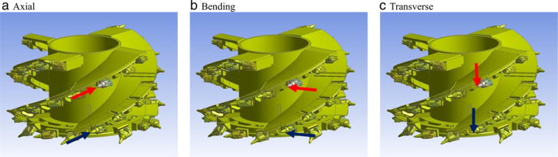
To address the above physical constraints and to comply with the permissibility requirements8, NIOSH in collaboration with Kennametal and Michigan Technological University developed a self-contained, intrinsically safe instrumented bit to measure in situ operational coal cutting forces9. The data acquisition system fitted inside the bit is a three-input-channel capable of sampling data at a rate of 100 kHz and was powered by a 9.6 V NiMH battery. The bit also contained three strain bridges that were calibrated to measure forces in the three directions: axial, bending and transverse, as shown in Fig. 6.
Fig. 6.

Direction of measured forces with respect to the bit holder.
Figure 7 shows typical time data of the coal cutting forces measured by the instrumented bit collected from an actual shearer under normal operating conditions; during this test, the longwall shearer drums were only cutting coal (i.e. no overburden). The web depth during this test was 0.6 m (2 ft) and the instrumented bit was mounted in a bit holder located mid-way between the face ring and the gob side of the leading drum. From these data it is apparent that the forces in the axial direction have the highest amplitude 20,016 N (~4,500 lb), followed by the bending forces 6,672 N (±1,500 lb) and the transverse forces 6,672 N (±1,500 lb). Figure 7 shows a sharp increase in the amplitude every time the bit engages with the coal during the cutting process, followed by a sharp decrease in the amplitude while the drum completes a rotation and the bit is not engaged with the coal. During the data acquisition process, the shearer drum was rotating at approximately 55 rpm, which is reflected on the period of the amplitude of the peaks shown in Fig. 7.
Fig. 7.

Time data of the forces measured by the instrumented bit.
The time data were post-processed and converted into the frequency domain using the Fourier transform to assess the frequency content of these forces. To this end, data sampled at 50 kHz while the drum was exclusively cutting coal was processed, averaging 15 records of 65,536 points each and using a Hamming window with 50% overlap. Figure 8 shows the power spectral density (PSD) of the data shown in Fig. 7. From this figure it can be seen that the force amplitude is relatively constant up to around 100 Hz. From this point on, the amplitude of the force “rolls down” at a rate inversely proportional to the frequency squared.
Fig. 8.

Power spectral density of the force measured by the instrumented bit.
4 NOISE SOURCE IDENTIFICATION
Before the numerical models of the cutting drum could be used to explore different noise control concepts, it was necessary to determine what part(s) of the drum were responsible for most of the sound radiated. To this end, a panel contribution analysis was performed – using the numerical BE model of the cutting drum – where the whole drum was divided into three parts: the cylindrical shell face, the inner vane segment faces and the outer vane segment faces, as shown in Fig. 9. During this analysis, only one of these parts is assumed flexible while the other two are set to be rigid. The excitation was applied in the same manner as in prior work and the predicted overall sound energy distribution is shown in Fig. 10. This analysis reveals that the energy of the noise generated by the vanes, which is the summation of the yellow and blue segments, dominates the total noise radiated by the drum. Furthermore, it is observed that the outer vane segments contribute more than the inner vane segments to the total noise radiation10. This information suggests noise control strategies to reduce the radiated noise.
Fig. 9.

FE-BE faces for: (a) Whole drum, (b) Cylindrical shell, (c) Inner vane segments and (d) Outer vane segments.
Fig. 10.

Overall sound energy distribution.
5 NOISE CONTROL CONCEPTS
The validated FE and BEM models of the cutting drum and the operational coal cutting forces measured with the instrumented bit, were used to study three different noise control concepts11. At this stage, only the potential of each control concept to reduce the sound radiated by the drum was assessed. This section presents a summary and a brief evaluation of the three noise control concepts that were studied as part of this research.
5.1 Bit Isolation
The goal of this noise control concept is to prevent the dynamic coal cutting force from being transmitted from the cutting bits to the main drum structure. To isolate the dynamic coal cutting force, the top layer of the connecting mass block with a thickness of 0.0254 m (1 inch), shown in Fig. 11(c), was given the properties of a rubber material, i.e. 80 shore A durometer with a Tensile Modulus of 6.89 MPa (1,000 psi) since the properties of the rubber materials are specified further in this section. The rest of the connecting mass block shown in Fig. 11(b), the bit and bit holder system shown in Fig. 11(d) and the main part of the drum were all still given the material properties of steel. For the baseline case, the whole drum was defined as steel.
Fig. 11.

Description of the bit isolation concept: (a) Bit assembly, (b) Connecting mass block, (c) Rubber material and (d) Bit and bit holder.
For the bit isolation case, in the frequency range of interest (below 2 kHz), the bit and bit holder vibrate almost as a rigid body with relatively low natural frequencies, due to the flexibility provided by the rubber layer. Meanwhile, the main part of the drum has many flexible modes with relatively high natural frequencies, some of which are significant contributors to the total noise radiation. For frequencies above the highest natural frequency for which the bit and bit holder behave as a rigid body, the force transmitted to the main part of the drum can be significantly reduced, due to the −20 dB/decade slope of the transfer function. However, at frequencies where the bit and bit holder behave as a rigid body, larger forces can be transmitted to the main drum structure due to the resonance.
To reduce the force transmission for all the frequencies, the drum design can be modified so that the highest natural frequency of the bit and bit holder assembly rigid modes is lower than the first flexible mode of the main drum structure. Practically, the natural frequencies of the bit and bit holder system can be adjusted by using different rubber materials. In this study, a practical industrial rubber material was used to evaluate the effect of the bit isolation concept on the sound radiation, i.e. 3.3 MPa Young modulus and 70 shore A durometer and a significant sound power reduction (around 26 dB) was achieved. However, after discussing this concept with cutting drum design engineers, it was concluded that this concept is not suitable for the cutting drum case due to the extreme working environment and bit isolation would probably cause durability and most importantly cutting performance issues.
5.2 Damping Treatments
An experimental modal analysis test conducted on a newly manufactured drum indicated that the longwall cutting drum is very lightly damped5. A uniform 0.01 loss factor was used for the structure in the structural-acoustic simulation as an approximation of the damping ratio obtained experimentally10. Due to the small damping ratio, there are many sharp peaks in the predicted sound power level spectra. Those peaks can be suppressed by increasing the damping ratio of the drum. Therefore, the effect of damping treatment on the predicted overall sound power level of the noise radiated by the longwall cutting drum was evaluated.
The overall sound power level below 2 kHz predicted using a uniform 0.01 loss factor was taken as the baseline. The overall sound power levels for two additional cases, one with a uniform 0.02 loss factor and another with a uniform 0.03 loss factor, were calculated and compared with the baseline prediction. These calculated values for the two cases show that overall sound power level reductions can be achieved by increasing the loss factor (a 3 dB reduction for a 0.02 loss factor and a 5 dB reduction for a 0.03 loss factor).
Despite this potential in noise reduction, the damping treatment concept is not an effective noise control strategy for the longwall cutting drum. On the one hand, it is not practical to implement a damping treatment on the whole cutting drum. On the other hand, implementing a damping treatment on the outer vane segments, which contribute the most to the total noise radiation, would be much easier and more practical. However, the largest reduction yielded by this noise control concept is approximately 3 dB, due to the fact that the noise generated by vibration of the outer vane segments accounts for roughly 50% of the total noise radiated by the whole drum, as shown in Fig. 10.
5.3 Structural Modifications
The predicted sound power level spectrum has two dominant characteristics that directly relate the sound power level spectrum to the structure vibration and provide an excellent basis for developing structural modifications for suppressing noise radiation. The first characteristic is that the sound power level will have large amplitude when the direction of the dynamic deformation of the cutting bit either aligns with or has a large component along the direction of the excitation force. A straightforward solution is to minimize the amplitude of the cutting bit dynamic deformation in the frequency range of interest by increasing the stiffness of the cutting bit assemblies. The second characteristic is that the outer vane segment vibration contributes the most to the total noise radiated by the longwall cutting drum. Reducing the number of modes of the outer vane segments in the frequency range of interest will reduce the noise.
Based on these two characteristics, the goal of this noise control concept is to increase the stiffness of the most significant sound-radiating structures which, in this particular case, are the outermost vane plates. To achieve this task, a set of stiffeners was developed in the form of gussets, thickening plates and ribs. This solution is the result of refining various types of stiffeners with input provided by Joy Global, a longwall system manufacturer, to make this solution practical and easy to implement. The final set of stiffeners is shown in Fig. 12 and consists of one gusset per bit holder structure along the four helical vanes, thickness-increasing plates along the edge of the helical vanes and a set of eight ribs in the face ring opening. Modal analysis results of the modified cutting drum with stiffeners show that the number of modes in the frequency range of interest (below 2 kHz) was reduced by around 70 (originally about 250 modes). Along with reducing the number of modes in the frequency range of interest, the structural modifications also reduced the amplitude of the drum response (displacement, velocity and acceleration) which, in turn, has an effect of the radiation efficiency of the various modes.
Fig. 12.

Noise controls that stiffen the sound radiating structures: (a) Gussets, (b) Thickening plates and (c) Ribs on the face ring.
Structural modification is the recommended noise control for the longwall cutting drum due to its ease of implementation relative to other noise control concepts and its ability to survive in the severe working environment of underground mines. Implementing structure modification involves manufacturing processes that are commonly used by the drum manufacturer. To assess the performance of the recommended structural modification, three different cases with excitations applied at different cutting bits were analyzed. First, the mode shapes of the modified drum were computed using the structural model and then these results along with the excitation forces were used as input to the boundary element model to predict the acoustic radiation due to these forces. This set of stiffener noise controls provided a noise reduction in the overall A-weighted sound power level below 2,000 Hz ranging between 3 and 4 dB depending on the location of force application. For all three cases, the coal cutting forces measured with the instrumented bit were applied as the excitation. The predicted overall sound power level below 2 kHz was compared with the baseline prediction. The simulation results showed that a promising sound power level reduction (of approximately 3 dB) can be achieved by performing structural modification of the longwall cutting drum.
6 EVALUATION OF SELECTED NOISE CONTROLS
6.1 Laboratory Tests
The construction and evaluation of the modified shearer drum was completed in two distinct steps: first, a standard, i.e. baseline, drum was built and tested and then the noise controls were implemented and tested on the modified drum. This two-step process allowed for experimental evaluation of the standard drum as well as the modified drum in a laboratory setup. Without the two-step approach, it would not have been possible to obtain the true baseline. A sound power level determination according to ISO 3743-212 was conducted in reverberation chamber NVLAP accredited to ISO 3741/ANSIS12.5113 standards. For these tests, the drum was placed face side down on nine inflatable supports, also known as AirRides and the excitation was provided using a modal shaker as shown in Fig. 13.
Fig. 13.

Experimental setup used for acoustic and vibration tests.
Figure 14 shows a drawing of the cutting drum with the direction of the excitation forces that were applied on Point 65 (red arrows) and on Point 264 (blue arrows). The axial force was applied along the axis of the bit, the bending force was perpendicular to the axial force and on a horizontal plane and the transverse direction was applied on the vertical plane.
Fig. 14.
Force excitation directions on Point 65 (red) and on Point 264 (blue).
Figure 15 shows a comparison of the sound power spectrum computed from the numerical models, i.e. finite element and boundary element model, simulation results (green bars) and the sound power spectrum computed from laboratory measurements of an actual drum (red bars) for Point 65 on the left column and for Point 264 on the right column. To compute the BEM results, the first 400 structural modes in the 0–2,900 Hz frequency range – obtained from a modal analysis of the finite element model of the drum – were used. These spectra show a good agreement between 200 and 800 Hz. Below 200 Hz, the BEM models predict higher sound power levels; it is suspected that the differences in these low frequencies are due to the difference in the model support. In the case of the BEM models, a free-free support condition was used; however, in the case of the actual drums, inflatable air supports that do have stiffness in the directions of force application were used. Above 800 Hz, the BEM models predict lower sound power levels due to the fact that only the first 400 structural modes were used in the computation.
Fig. 15.

Comparison of the sound power level computed from the BEM model and from laboratory measurements of a standard drum for Point 65.
In terms of noise reduction, Fig. 16 shows a sound power spectra comparison between the standard drum (i.e. baseline drum) and the drum with the implemented noise controls (i.e. modified drum). These results were computed from laboratory measurements conducted on an actual set of drums. From Fig. 16 it can be seen that the developed noise controls have a significant effect between 400 and 800 Hz with reduction of up to 20 dB when the force is applied along the axial and bending directions and reductions of up to 10 dB when the force is applied in the tangential direction. In terms of overall sound power level, these differences in spectra translate into a 3 to 6 dB reduction depending on the location and direction of the force application.
Fig. 16.

Sound power radiated due to an excitation force on a bit, measured at NIOSH reverberation chamber.
6.2 Underground Evaluation
The underground tests were conducted to measure the effect of the noise controls at the longwall shearer operator’s location with all other noise sources present during normal operation—most notably the noise generated by the interaction of the ripped coal with different parts of the shearer and the armored face conveyor, the water spray noise sources and the electric and hydraulic noise sources. The operator was located in the walkway directly across the leading drum. Sound level measurements were conducted in November of 2014 while the collaborating mine was operating with a standard longwall cutting drum; then, in April of 2015 these sets of measurements were repeated when the mine was operating using the modified set of longwall cutting drums. On both occasions, data were collected under similar mining conditions and with the longwall system running with the same parameters such as depth of cut, tramming speed and rotational speed of the drums. Measurements were conducted right at the operator location, directly across from the leading cutting drum. Data was collected only during the tailgate to headgate cut, not during the return cut.
Sound pressure time data were recorded using an MSHA-permissible audio recorder. These data were then converted into the frequency domain using a fast Fourier transform (FFT) algorithm to obtain the sound pressure spectrum. Figure 17 shows the linear and A-weighted one-third octave band spectrum of the data recorded at the collaborating mine while operating with the standard (baseline) drums as well as the spectrum of the data recorded while operating with the modified cutting drums. The spectra show a reduction throughout the frequency range. This broadband reduction is a major accomplishment that could probably not have been attained with any of the other noise control options. In terms of overall sound pressure level, a reduction of approximately 3 dB is observed from the linear spectra; however, when these spectra are A-weighted, the overall sound pressure level reduction is approximately 6 dB.
Fig. 17.

Sound pressure spectra of the standard (baseline) drum in gray bars and the modified drum in yellow bars, computed from audio recordings at the shearer operator location during normal operation.
7 CONCLUSIONS
Noise controls for longwall cutting drums were developed using a numerical modeling approach. The controls consisted of structural modifications aimed at stiffening the most significant sound-radiating components of the cutting drums. The controls were implemented into an actual set of drums and installed on a longwall shearer for production of an entire longwall panel. Results from the underground evaluation show noise reduction across the entire frequency spectrum with overall noise reductions of 3 and 6 dB from the linear and A-weighted spectra, respectively. The broadband noise reduction represents a major accomplishment that could likely not be attained with any other noise control option without adversely affecting the cutting performance, the structural integrity, or the loading ability of the drum.
It is important to note that the 3-dB reduction predicted by the numerical models was verified in the underground tests despite the variability of conditions and despite the presence of many other noise sources during normal operation of the cutting drum. Although every set of drums is different for every mine, the particular noise controls developed in this study may not provide the best noise reduction for other drums. However, the results obtained from the underground evaluation constitute a clear indication that modeling can accurately predict noise reductions and can be used to develop noise controls for other drums. Furthermore, based on the high level of accuracy demonstrated here, these results show that future work to further reduce the sound radiated by longwall systems can be done with these types of numerical models.
Acknowledgments
The authors would like to thank Joseph Defibaugh and Mike O’Neill from Joy Global for all their support and coordination throughout the various stages of the project. Thanks are also due to all the Joy Global personnel that provided valuable input at different stages of the project and most importantly for supporting and showing their confidence in NIOSH’s work. It was through their support that the noise controls were implemented into an actual set of drums and evaluated in an underground environment.
Footnotes
The findings and conclusions in this report are those of the authors and do not necessarily represent the views of the National Institute for Occupational Safety and Health. Mention of any company name, product, or software does not constitute endorsement by NIOSH.
Primary subject classification: 14.3.2; Secondary subject classification: 41.3
References
- 1.Tak SW, Calvert GM. Hearing difficulty attributable to employment by industry and occupation: An analysis of the National Health Interview Survey — United States, 1997 to 2003. J Occ Env Med. 2008;50(1) doi: 10.1097/JOM.0b013e3181579316. [DOI] [PubMed] [Google Scholar]
- 2.Franks JR. Analysis of Audiograms for a Large Cohort of Noise-Exposed Miners. National Institute for Occupational Safety and Health, Internal Report. 1997 [Google Scholar]
- 3.Title 30 CFR Part 62, 2002–2011. U.S. Department of Labor, Mine Safety and Health Administration, Information Resource Center
- 4.Pettitt MR, Slone R. Noise Study of Longwall Mining Systems. Contract Report JO188072. 1986 Prepared by Wyle Laboratories for the United States Bureau of Mines. [Google Scholar]
- 5.Camargo HE, Yantek DS, Smith AK. Development of a validated finite element model of a longwall cutting drum. InterNoise. 2012;12 [Google Scholar]
- 6.Acoustics — Determination of sound power levels of noise sources using sound pressure — Engineering method in an essentially free field over a reflection plane. International Standard ISO 3744, International Organization for Standardization; 1994. [Google Scholar]
- 7.Yang J, Camargo HE, Yantek DS. Sound radiation modeling and correlation of a longwall cutting drum. NoiseCon. 2013;13 [Google Scholar]
- 8.Title 30 Code of Federal Regulations (CFR), Subpart F, 75.500, Electrical Equipment — General.
- 9.Camargo HE, Gwaltney G, Alcorn L. Development of an instrumented longwall bit to measure coal cutting forces for use in developing noise controls. Mining Engineering. 2015 [Google Scholar]
- 10.Yang J, Camargo HE, Yantek DS. Sound radiation analysis of a longwall cutting drum. ASME IMECE; 2013. [Google Scholar]
- 11.Yang J, Camargo HE, Yantek DS. Noise control concepts for a longwall cutting drum. Vol. 14. NoiseCon; 2014. [Google Scholar]
- 12.Acoustics — Determination of sound power levels of noise sources using sound pressure — Engineering methods for small, movable sources in reverberant fields — Part 2: Methods for special reverberation test rooms. International Standard ISO 3743-2, International Organization for Standardization; 1994. [Google Scholar]
- 13.Acoustics — Determination of sound power levels of noise sources using sound pressure — Precision methods for reverberation rooms. International Standard ISO 3741, International Organization for Standardization; 1999. [Google Scholar]