Abstract
Nasal tip mechanical stability is important for functional and cosmetic nasal airway surgery. Palpation of the nasal tip provides information on tip strength to the surgeon, though it is a purely subjective assessment. Providing a means to simulate nasal tip deformation with a validated model can offer a more objective approach in understanding the mechanics and nuances of the nasal tip support and eventual nasal mechanics as a whole. Herein we present validation of a finite element (FE) model of the nose using physical measurements recorded using an ABS plastic-silicone nasal phantom. Three-dimensional photogrammetry was used to capture the geometry of the phantom at rest and while under steady state load. The silicone used to make the phantom was mechanically tested and characterized using a linear elastic constitutive model. Surface point clouds of the silicone and FE model were compared for both the loaded and unloaded state. The average Hausdorff distance between actual measurements and FE simulations across the nose were 0.39mm ± 1.04 mm and deviated up to 2mm at the outermost boundaries of the model. FE simulation and measurements were in near complete agreement in the immediate vicinity of the nasal tip with millimeter accuracy. We have demonstrated validation of a two-component nasal FE model, which could be used to model more complex modes of deformation where direct measurement may be challenging. This is the first step in developing a nasal model to simulate nasal mechanics and ultimately the interaction between geometry and airflow.
INTRODUCTION
Rhinoplasty is a surgical procedure that focuses on changing the shape of the nose for either functional (airway) or cosmetic purposes. Maintaining or increasing nasal tip support after surgery is the most important element of both functional and cosmetic rhinoplasty and exceptionally important in order to achieve predictable steady-state outcomes. Rhinoplasty surgery is technically challenging and revision rates (failure) historically vary between 10–15%2, 4, 19, 25. Prior to performing surgery, one of the surgeon’s most informative physical examination maneuvers is nasal tip palpation. Solely relying on fingertip sensitivity, the surgeon can formulate a subjective assessment on nasal tip strength and stability based upon assessing recoil to depression. This assessment is based on years of practice and clinical experience. As such, it would be valuable to devise a reliable metric able to quantify the strength and stability of the nasal tip to confirm a surgeon’s intuition. This quantification and validation work has never been done before. Though, some devices have been constructed to measure tip recoil but have not been adopted for use or validated 1, 6.
In the nose, the use of finite element analysis to predict the stress and strain distribution under certain loading conditions as a result of simulated surgical modifications 3, 7, 10, 11, 13, 15, 26 has been reported, but with abbreviated anatomic models (incomplete anatomy) and no validation of results with experimental measurements. The majority of the nasal finite element analysis has been limited examining the underlying cartilage tissue alone (septum and alae) and does not consider the effect of the overlying skin-soft tissue envelope or adjacent bone 11, 13. Obviously, the most meaningful predictions and reliable conclusions are best established using a validated model. Nasal tip depression (palpation) is the simplest and most important physical examination maneuver to perform and simulate, but must first be validated before meaningful interpretation of more complex nasal modeling can be performed. Examples of more complex models include how the nasal airway collapses during airflow, and how virtual surgery implemented in an FEM might be used to guide and select actual surgical procedures.
This report presents a finite element analysis of a human nasal model and compares predictions with outcomes measured using a silicone phantom. Nasal tip deformation is measured in the model and compared to predictions of the FEM.
A nasal phantom made of silicone and acrylonitrile butadiene styrene (ABS) plastic was 3D printed using computed tomography (CT) data, then loaded at its tip. The geometry of the nose is identical to our previous studies on nasal tip support in response to tip depression 15, 26. Deformation was recorded using 3d photography and the resulting geometry was compared to results of the finite element model. The comparison was performed by cloud comparison by projecting the reference set of nodes captured via 3D photography onto the nodes of the finite element model.
METHODS
Manufacturing Process of a silicon 2-component sample
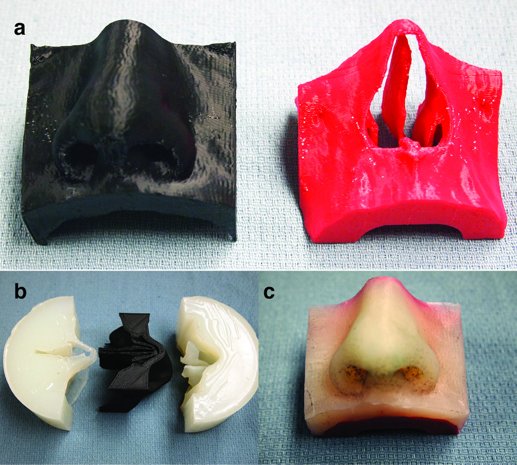
A mechanical nasal phantom was constructed from two materials: ABS plastic for bone and silicone for the nose and soft tissue. Geometry was derived from a high-resolution CT head scan of a single patient, which was processed using computer-aided design software (Mimics, Materialise, Leuven, Belgium). DICOM images of the nose in the axial plane were imported into Mimics (Materialise, Leuven, Belgium) and soft tissue and bone were segmented. Gaussian and tessellated surfaces of bone and soft tissue were created and a triangle reduction function was performed. The surfaces were remeshed again to have triangular elements with edges less than 2mm and were exported in stereolithography format (STL). A 3D printer (Replicator 2, MakerBot, New York) and its proprietary software, was used to print in ABS the bone and soft tissue components independently (Figure 1a). As the soft tissue component needed to be constructed from silicone, the ABS soft tissue 3D print was molded and casted in Dragon Skin® silicone (Dragon Skin® 10 Slow, Smooth On, Pennsylvania). After mold curing, the plastic model (positive) was removed from the Dragon Skin® silicone mold (negative) (Figure 1b). A releasing agent (Ease Release® 200, Mann Formulated Products, Pennsylvania) was sprayed inside the mold, placed back inside the cylindrical container, and silicone was poured to fill the inner cavity of the mold. Once cured, the silicone nose was removed and glued to the ABS bony compartment (Figure 1c).
Figure 1.
The molding and casting process. a) The bone and soft tissue components printed in ABS plastic. b) The resulting mold from the ABS soft tissue. c) The completed nasal phantom with silicone representing the soft tissue and the bone representing ABS plastic.
Material Characterization of the silicone
The soft tissue component of the nasal phantom is made of silicone. As such, a hyperelastic constitutive model would be best suited to describe the nonlinear stress-strain, incompressible, and strain rate behavior of this material16. It is arguable, however, that the range of deformation experienced during nasal tip palpation (depressing the nasal tip) could be accurately characterized using a small strain formulation. The prediction of these infinitesimal strains under applied loading can be fully described using an isotropic linear elastic model. The value of Poisson’s ratio is assumed to be equal to ν = 0.49 (owing to the incompressibility of the silicon), while the determination of Young’s modulus is herein presented based on uniaxial test data.
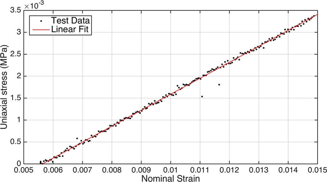
The recording of test data was limited to small strains since the range of deformations experienced by the nose during nasal tip palpation can be predicted using a small strain theory. A rectangular silicone sample was cast (Dragon Skin® 10 Slow, Smooth On, Pennsylvania) (12 cm × 1 cm × 1 cm) and was mechanically tested (ELF, sensitivity of 0.05 grams and a maximum capacity of 250 grams, Enduratec Bose, Framingham, MA)‥ The measurement proceeded with the linear actuator displacing the silicone bar to a 2.4% strain, which corresponded to the limit of the load cell. Tensile force and displacement was recorded at a strain rate of 0.01 mm/s and presented in Figure 2.
Figure 2.
Stress-strain curve of rectangular silicon sample and curve fitting with linear elastic model.
The initial slope of the curve, corresponding to the elastic modulus of the material, was found to be equal to E = 0.364 MPa.
Experiment Setup & 3D reconstruction of Nasal Phantom
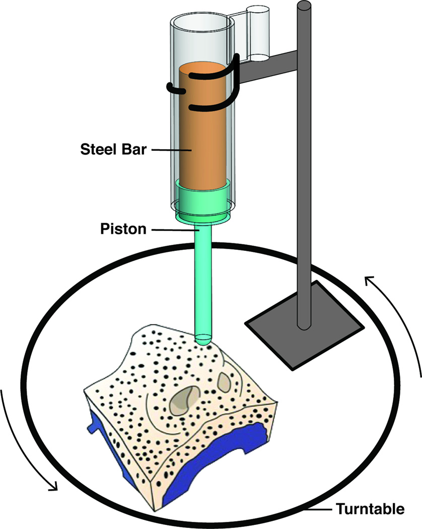
Photogrammetry was used to provide data to reconstruct the nasal phantom before and after nasal tip depression. A schematic of the experimental setup used to measure the 3D deformation of the nose is illustrated in Figure 3 and consisted of the nasal phantom, a turntable, a custom loading apparatus, diffuse lighting elements, and a digital camera.
Figure 3.
Experimental setup of nasal tip deformation.
Nasal tip palpation was modeled as a step displacement of the nasal tip. In this approach, a custom-built loading apparatus designed in Solidworks (Dassault Systemes, Vélizy-Villacoublay, France) and constructed in ABS plastic (Figure 3). The steel rod weighed 500 grams and the piston assembly (ABS) weighed 13 grams. The value of 500 g for the loading weight was selected as it produced a realistic and clinically relevant displacement of the nasal tip.
To optimize surface reconstruction of the nasal phantom, diffuse lighting (soft boxes) and speckle patterning of the surfaces with a fine marker being photographed were employed. A “speckle” pattern provides surface features that aid in 3D reconstruction. Ink (Brother, Bridgewater, New Jersey) was also freshly applied onto the end of the piston shaft to demarcate (“stamp”) the contact surface between the piston and the nasal tip of the phantom model.
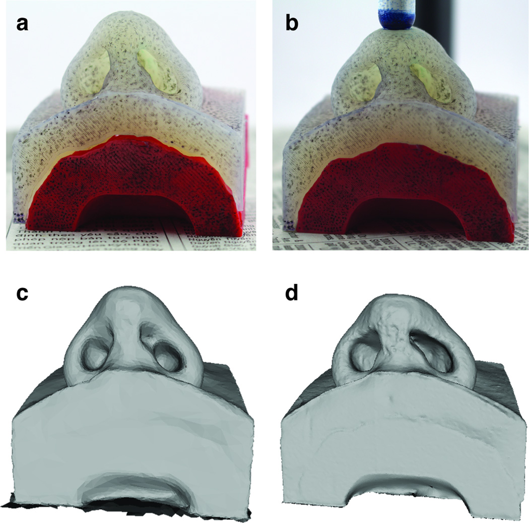
Two measurements were performed: 1) the nasal phantom without load and 2) the nasal phantom with load. The unloaded case was initially performed and did not require the use of the loading apparatus. In this case, the nasal phantom was placed onto the turntable. A digital single-lens reflex camera (Canon Rebel T5i, Cannon, New York) with an 18–55 mm lens recorded images at three camera angles (eye level, 30°, and 60° above the plane of the platform), and at intervals 15° (24 rotations of the turntable for each elevation). The process was repeated again only this time with the inclusion of the loading apparatus. An example of experiment photos in its loaded and unloaded state is shown in Figure 4a–b. A total of 70 images (software maximum) were imported into 123D Catch (Autodesk Inc, San Rafael, CA, USA) to produce 3D renderings of the nasal phantom in its undeformed and deformed state. The undeformed and deformed surface meshes produced by 123D Catch was imported into 3DS Max (Autodesk, San Rafael, CA, USA) for editing. Each model was edited to remove structures not associated with the nasal model, but reconstructed by 123D Catch (e.g. the turntable). The adjusted 3D photogrammetric model was then exported in STL format (Figure 4c–d) to be compared with the finite element models.
Figure 4.
Photographs of the nasal phantom in the loaded and unloaded state and the resulting reconstructions. a) Photo of unloaded nasal phantom. b) Photo of loaded nasal phantom. c) 123D catch reconstruction of the unloaded nose. d) 123D catch of the loaded nose.
Numerical Simulation of Nasal Tip Displacement
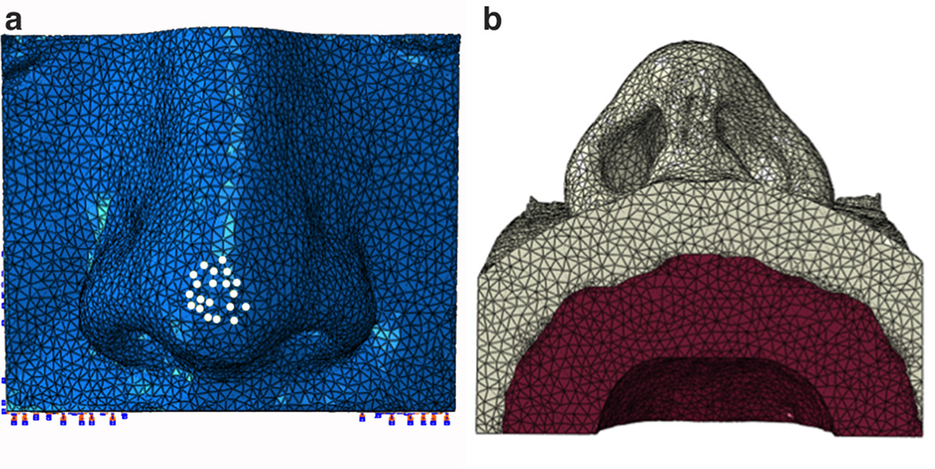
The bone and soft tissue surface meshes that were exported from Mimics and used to construct the mechanical phantoms were also used to generate the FEM. Meshes were imported into Hypermesh (Altair Engineering, Troy, Michigan) to generate a single volumetric mesh model and to define boundary conditions that mimic the physical experiment. A tetrahedral mesh was created from the imported bone and soft tissue STLs and nodes were equivalenced to combine all coincident nodes at the interface between the soft tissue and bone boundaries. Nodes within the bone volume were constrained. In order to accurately identify nodes that will undergo loading as observed in the experiment, a surface mesh of the deformed nasal phantom model (123D catch model) was imported and aligned in registry with finite element model. The overlapping nodes that underwent deformation were labeled on the FEM to be prescribed a loading condition. Information containing node locations, element connectivity and loading conditions were exported in a specific .inp format to be used in ABAQUS for simulation and post-processing.
Our finite element nasal model consisted of a collection of C3D4H finite elements: a 4-node linear tetrahedron, hybrid, and linear pressure. Prescribed load and boundary conditions of the finite element model in ABAQUS is illustrated in Figure 5. The bone component of the finite element model, shown in red, was assigned linear elastic material properties of ABS plastic with a comparatively high tensile modulus of 2 GPa and the whole component was held fixed. By comparison, cortical bone can have an elastic modulus range between 5 to 15 GPa 18. To model the silicone component of the 123D Catch Model, the soft tissue component of the finite element model was assigned elastic material properties of very low modulus properties as determined above and a load was prescribed at the nasal tip as indicated by the white nodes in Figure 5a.
Figure 5.
Finite element discretization of nasal model with boundary and loading conditions. a) Frontal view of the model with white dots indicating the nodes that were prescribed a loading condition. b) Base view of the model. Soft tissue in light grey was assigned linear silicone properties and bone tissue in red was assigned ABS plastic material properties.
Point Cloud Comparison for Validation
Validation was accomplished by comparing the steady state geometry of the finite element model with the model obtained from displacing the tip of the silicone model. Point clouds were generated for the surfaces of each model. CloudCompare (http://www.danielgm.net/cc/) was used to calculate the similarities between corresponding surfaces and is a software environment optimized for using point cloud data. CloudCompare evaluates a subset of points of one object and compares it to the subset of points of the other object being compared. It then calculates the directed Hausdorff distance 9 which is the maximum distance of a set of points to the nearest point in the other set. This methodology uses the nearest neighbor search to define each subset of points to be compared. As such, It is important to implement this software using a dense point cloud space, so that the distances between the underlying surface representing the reference cloud (finite element model) and the compared cloud (3D photography derived model) are sufficiently accurate. In order to assess the reliability of the software and our 3D photography system, the undeformed geometries of the 3D photography derived model and finite element model was compared before comparing the deformed geometries.
RESULTS
3D Point Cloud Comparison for Undeformed Geometries
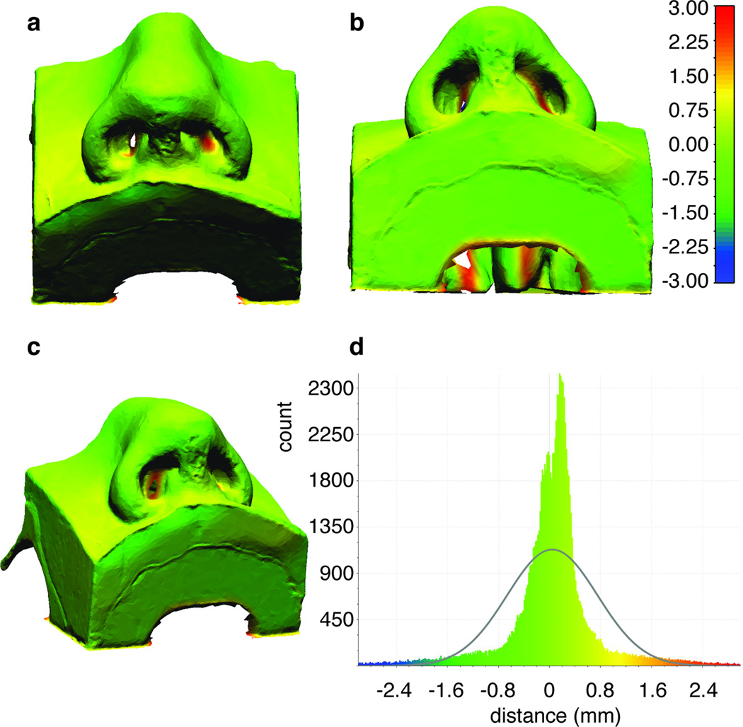
There was a good overlap between the point cloud derived from 3D photographic reconstructions of the silicone nose model and the FEM model produced directly from CT data when no displacement or load was applied. The reconstructed surface model had a volume of 96.2 ml with 16,571 nodes and 33,146 triangles. A colormap showing the relative distances between the two models is shown Figure 6, the differences between the two models are well under a millimeter, with an average of 0.15 mm and a standard deviation equal to 0.77 mm. The nasal tip (most important region of interest) exhibits excellent agreement between the two geometries. The data is skewed by comparison between regions far away from the nasal tip such as along the edges of the model, the back of the model and the inside of the nares (nasal cavities are poorly resolved using 3D photography, as expected). Differences at these peripheral edge areas may range from 1.5 to 3 mm. These differences are less important as accurate representation of the sample edges is less relevant for the proper modeling of nasal tip palpation (displacement). Regions within the nasal cavities also show these significant deviations. Regardless, the borders of the nostrils are still captured well with requisite accuracy using digital photography.
Figure 6.
Point cloud comparison and signed distances (mm) between the undeformed finite element and undeformed 123D catch model. a) Perspective view. b) Base view. c) Oblique view. d) Histogram plot of the signed distances.
3D Cloud Comparison for Deformed Geometries: Validation
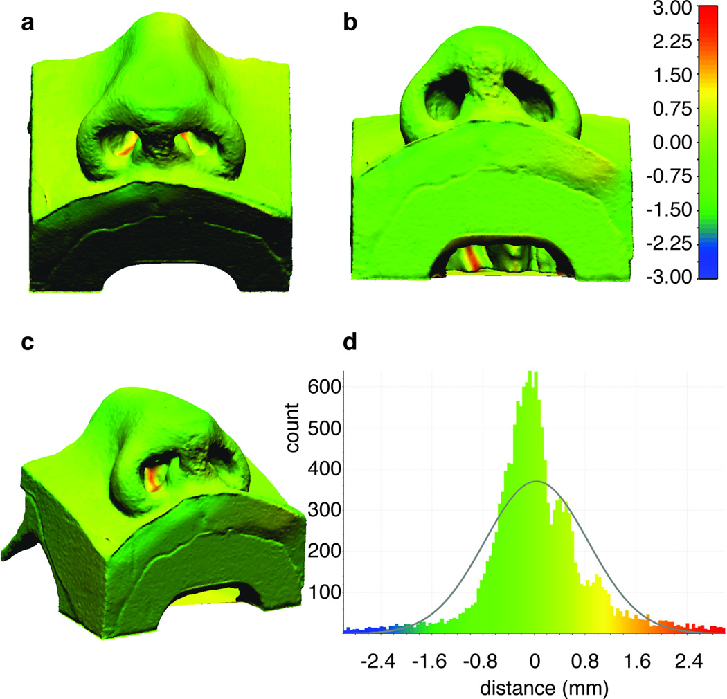
Since there was good agreement between the two models in native undeformed (zero stress) state, the shape change in the nasal surface produced by loading the nasal tip with results predicted by the FEM were compared. The reconstructed surface model had a volume of 90.0 ml with 115,258 nodes and 230,415 triangles. Similar to the unloaded case, the finite element models are in excellent agreement with the point cloud obtained from 3D photography of the silicone phantom depressed using the cylinder-piston apparatus. Using a Gaussian fit it is found that the mean is around 0.39 mm and the standard deviation in the vicinity of 1.04 mm. A greater number of paired points have a distance larger than 2 mm in absolute value, as seen in Figure 7. However, these discrepancies again are predominantly along the periphery of the models- at back of the sample, around the edges, inside the nostrils, and away from the loaded tip.
Figure 7.
Point could Comparison and signed distances (mm) between the reference finite element model and the deformed 123D catch model. a) Perspective view. b) Base view. c) Oblique view. d) Histogram plot of the signed distances.
DISCUSSION
Surgeons rely on nasal tip palpation to assess the overall mechanical integrity of the nose, and this component of the physical examination remains among most important pre-operative evaluations for the rhinoplasty surgeon. Rhinoplasty is a technically challenging and complex surgical procedure with revision (failure) rates varying from 10–15%2, 4, 19, 25. To the general public it is often viewed dismissively as purely a cosmetic procedure. In reality, rhinoplasty more often than not is performed to correct deformities due to trauma or congenital malformation, and also to correct dynamic airway collapse leading to obstruction12, 17. The nasal airway is a complex structure made of both static and dynamic components. The dynamic components change (flex, collapse) with varying degrees of airflow, and because of the complex shape of the nasal vault, identifying the site of obstruction and correct operation to perform is frequently a challenge. Modeling and ultimately developing a comprehensive fluid-structure interaction would be essential to developing individualized patient specific surgical techniques to treat the obstructed nasal airway 7, 8, 21, 27. Modeling may also have utility in determining the long-term outcomes of surgery on nasal structure, and has already been used to predict surgical complications 15, 26. This study is the first step needed to validate a nasal FEM and here focuses on steady-state formulations 15, 26. Here the mechanical behavior and nasal shape under various loading conditions were measured in our nasal phantom and agreed reasonably well with predictions generated by the FEM.
Validation of a nasal FEM ideally would be performed in human subjects, but that is challenging as little is known about the mechanical properties of the nasal tissues (cartilage, bone, skin, assorted ligamentous structures), tissues are generally anisotropic, and measuring tip support has been reported in the literature to yield extremely divergent outcomes 1, 6, 20. Hence using a human model to validate a finite element model is complex, and not the ideal first step in this process. We pursued a simplified phantom consisting of a soft tissue (silicone) and hard tissue (ABS) components. The ABS-silicone phantom was constructed using CT scan data that was previously used in other finite element simulations 15, 26. This approach, while not ideal provides a rational starting point to gain insight on steady state nasal mechanics, as the properties of the silicone could be specified and then measured precisely. In the physical model, ABS plastic is sufficiently high modulus to approximate bone extremely well given the relatively modest deformations that were made in the nasal tip. The use of silicone rubber to simulate non-osseous tissues is a bit more perplexing and challenging. The soft tissues of the nose are made of multiple individual components- skin, fascial tissue, and ligamentous structures. These are all collagenous materials that exhibit non-linear viscoelastic behavior, but fortunately are believed to be linear in general over relatively small deformations. Thin skin-soft tissue envelope may be reasonably approximated as one “lumped” component, and we believe use of silicon is a reasonable proxy for developing and refining an FEM. More challenging and difficult is constructing a physical model that also incorporates the cartilaginous structures of the nose, even though generating an FEM with cartilage is straightforward 15, 26.
Cartilage is mechanically complex tissue that maybe classified as either soft or hard depending upon the context in which it is discussed. Its behavior is multi-phasic, and even with high-level modeling techniques, is difficult to simulate, except in very simple modes of deformation. While we have modeled cartilage in finite element simulations, developing a three-component model with a second elastic or viscoelastic cartilage component is beyond the scope of this study. This however is an area of active research and pursuit by our group as we refine and develop our 3-D printing and casting capabilities.
The results of the simulation compare favorably with the surface measurements in the nasal phantom indicating that the simple linear elastic constitutive model adequately describes this behavior (Figure 7). The histograms and point cloud images in Figure 6d and Figure 7d show excellent overlap in both native and deformed cases. Though in this instance the geometry derived directly from CT and incorporated into the FEM was deemed the reference when no load was applied. It is important to note that, in order to generate a precise constitutive material model, the experimental test data on a block sample should be recorded over the range of strains experienced during a specific application. Due to the limitations of our mechanical testing apparatus, we were not able to stretch silicone to a larger range of displacements. In the case of extreme deformation and modeling hyperelasticity, large strains should be included during uniaxial testing.
Deviations between the photogrammetric reconstructions and the FEM that is derived purely from CT data may be attributed to how the model was made and recorded. Structures (point clouds) generated from 3D photography also may have limitations due to: 1) the printing and construction process of a physical model, and 2) photography and the 3D reconstruction process. The use of 3D imaging to create a surface model or point cloud with adequate resolution (approximately 1.3 nodes per mm3 deformed and 0.2 nodes per mm3 undeformed) is a novel application of this technology, though such approaches have been widely used in industry and other applications5, 14, 24. Complex geometries with deep crevices are an issue for reconstruction with software like 123D Catch because these types of shapes offer poor contrast for photography even with exceptional lighting conditions. The nostrils in our nasal phantom for example showed poor overlap with the finite element model (Figure 7) especially deep inside the nostrils. Reconstructions are not perfect and usually require editing of the surface mesh by deleting erroneous components not associated with the subject. Accuracy of these reconstructions is also limited to distortion and aberration of the lens. As technology advances, 3D video point clouds will be exceptionally valuable as modeling efforts move from static and steady state renderings toward dynamic simulations. Dynamic analysis would be important, as the behavior of the nose during breathing is critical; lateral nasal wall collapse is common and among the most frequent indications for rhinoplasty surgery.
Our numerical model was validated with a simple phantom with silicone representing cartilage, soft tissue, ligaments, and other connective tissue (Figure 3a), which limits in the accuracy of our predictions. The soft tissue component of nose is obviously composed of more than just one largely linear isotropic material. A feasible improvement would be to generate a three-component model, by differentiating the soft tissue from the cartilaginous component using two separate elastomers. Having a three-component nasal model leads to a fundamental question: what are the internal strains and stresses in the region of interest beneath the skin and how is the cartilage contributing to the load carrying capacity. Such information is easily derived numerically 15, 22, 23, 26, but constructing a physical model with multiple elastic components still presents a manufacturing challenge
Ultimately, the purpose of a validated nasal model is to perform parametric analysis with various intrinsic characteristics (shape, strength of cartilages) and ideally identify what structure is best to counter act the forces responsible for dynamic collapse. Nasal modeling can also be used to predict steady state outcomes of surgery13, 15, 22, 23, 26. This work is a stepping-stone towards this goal.
CONCLUSION
A FE model of nasal tip deformation was validated using photogrammetric measurements of a physical silicone and abs plastic model with millimeter accuracy around the nasal tip and outer nostrils. Mechanical testing of validated physical nasal models can provide reliable load and displacement measurements. Validating a three component physical model with cartilage as a separate material presents a challenge in terms of monitoring its internal structural changes. Overcoming this barrier would provide means to validate a more descriptive FE model and thus yield more realistic information on the static and dynamic behavior of the nose.
Acknowledgments
We would like to acknowledge our funding sources: NIH/NHLBI (1 R01 HL105215-01), NIH/NIBIB P41EB015890, Laser Microbeam and Medical Program (LAMMP), and the Hewett Foundation.
References
- 1.Beaty MM, Dyer WK, 2nd, Shawl MW. The quantification of surgical changes in nasal tip support. Arch Facial Plast Surg. 2002;4:82–91. doi: 10.1001/archfaci.4.2.82. [DOI] [PubMed] [Google Scholar]
- 2.Beekhuis GJ. Nasal obstruction after rhinoplasty: etiology, and techniques for correction. Laryngoscope. 1976;86:540–548. doi: 10.1288/00005537-197604000-00010. [DOI] [PubMed] [Google Scholar]
- 3.Conci RA, Tomazi FH, Noritomi PY, da Silva JV, Fritscher GG, Heitz C. Comparison of Neck Screw and Conventional Fixation Techniques in Mandibular Condyle Fractures Using 3-Dimensional Finite Element Analysis. J Oral Maxillofac Surg. 2015 doi: 10.1016/j.joms.2015.01.037. [DOI] [PubMed] [Google Scholar]
- 4.Cummings Charles W. Cummings otolaryngology head & neck surgery. Philadelphia, Pa.: Elsevier Mosby; 2005. [Google Scholar]
- 5.de Sainte Croix MM, Gauld D, Forgie AH, Lowe R. Three-dimensional imaging of human cutaneous forearm bite marks in human volunteers over a 4 day period. J Forensic Leg Med. 2016;40:34–39. doi: 10.1016/j.jflm.2016.02.003. [DOI] [PubMed] [Google Scholar]
- 6.Dobratz EJ, Tran V, Hilger PA. Comparison of techniques used to support the nasal tip and their long-term effects on tip position. Arch Facial Plast Surg. 2010;12:172–179. doi: 10.1001/archfacial.2010.33. [DOI] [PubMed] [Google Scholar]
- 7.Frank-Ito DO, Kimbell JS, Laud P, Garcia GJ, Rhee JS. Predicting postsurgery nasal physiology with computational modeling: current challenges and limitations. Otolaryngol Head Neck Surg. 2014;151:751–759. doi: 10.1177/0194599814547497. [DOI] [PMC free article] [PubMed] [Google Scholar]
- 8.Hariri BM, Rhee JS, Garcia GJ. Identifying patients who may benefit from inferior turbinate reduction using computer simulations. Laryngoscope. 2015 doi: 10.1002/lary.25367. [DOI] [PMC free article] [PubMed] [Google Scholar]
- 9.Huttenlocher DP, Klanderman GA, Rucklidge WJ. Comparing Images Using the Hausdorff Distance. Ieee Transactions on Pattern Analysis and Machine Intelligence. 1993;15:850–863. [Google Scholar]
- 10.Kimbell JS, Frank DO, Laud P, Garcia GJ, Rhee JS. Changes in nasal airflow and heat transfer correlate with symptom improvement after surgery for nasal obstruction. J Biomech. 2013;46:2634–2643. doi: 10.1016/j.jbiomech.2013.08.007. [DOI] [PMC free article] [PubMed] [Google Scholar]
- 11.Lee JS, Lee DC, Ha DH, Kim SW, Cho DW. Redefining the septal L-strut in septal surgery. PLoS One. 2015;10:e0119996. doi: 10.1371/journal.pone.0119996. [DOI] [PMC free article] [PubMed] [Google Scholar]
- 12.Lee MK, Most SP. Evidence-Based Medicine: Rhinoplasty. Facial Plast Surg Clin North Am. 2015;23:303–312. doi: 10.1016/j.fsc.2015.04.004. [DOI] [PubMed] [Google Scholar]
- 13.Lee SJ, Liong K, Tse KM, Lee HP. Biomechanics of the deformity of septal L-Struts. Laryngoscope. 2010;120:1508–1515. doi: 10.1002/lary.20976. [DOI] [PubMed] [Google Scholar]
- 14.Leipner A, Baumeister R, Thali MJ, Braun M, Dobler E, Ebert LC. Multi-camera system for 3D forensic documentation. Forensic Sci Int. 2016;261:123–128. doi: 10.1016/j.forsciint.2016.02.003. [DOI] [PubMed] [Google Scholar]
- 15.Manuel CT, Leary R, Protsenko DE, Wong BJ. Nasal tip support: A finite element analysis of the role of the caudal septum during tip depression. Laryngoscope. 2013 doi: 10.1002/lary.24321. [DOI] [PMC free article] [PubMed] [Google Scholar]
- 16.Martins PALS, Natal Jorge RM, Ferreira AJM. A Comparative Study of Several Material Models for Prediction of Hyperelastic Properties: Application to Silicone-Rubber and Soft Tissues. Strain. 2006;42:135–147. [Google Scholar]
- 17.Most SP. Analysis of outcomes after functional rhinoplasty using a disease-specific quality-of-life instrument. Arch Facial Plast Surg. 2006;8:306–309. doi: 10.1001/archfaci.8.5.306. [DOI] [PubMed] [Google Scholar]
- 18.Motherway JA, Verschueren P, Van der Perre G, Vander Sloten J, Gilchrist MD. The mechanical properties of cranial bone: the effect of loading rate and cranial sampling position. J Biomech. 2009;42:2129–2135. doi: 10.1016/j.jbiomech.2009.05.030. [DOI] [PubMed] [Google Scholar]
- 19.Neaman KC, Boettcher AK, Do VH, Mulder C, Baca M, Renucci JD, VanderWoude DL. Cosmetic rhinoplasty: revision rates revisited. Aesthet Surg J. 2013;33:31–37. doi: 10.1177/1090820X12469221. [DOI] [PubMed] [Google Scholar]
- 20.Oliaei S, Manuel C, Protsenko DE, Wong BJ. Biomechanical Properties of Facial Cartilage Grafts. New York: Springer; 2013. p. 37. [Google Scholar]
- 21.Patel RG, Garcia GJ, Frank-Ito DO, Kimbell JS, Rhee JS. Simulating the nasal cycle with computational fluid dynamics. Otolaryngol Head Neck Surg. 2015;152:353–360. doi: 10.1177/0194599814559385. [DOI] [PMC free article] [PubMed] [Google Scholar]
- 22.Rhee JS, Cannon DE, Frank DO, Kimbell JS. Role of virtual surgery in preoperative planning: assessing the individual components of functional nasal airway surgery. Arch Facial Plast Surg. 2012;14:354–359. doi: 10.1001/archfacial.2012.182. [DOI] [PMC free article] [PubMed] [Google Scholar]
- 23.Rhee JS, Pawar SS, Garcia GJ, Kimbell JS. Toward personalized nasal surgery using computational fluid dynamics. Arch Facial Plast Surg. 2011;13:305–310. doi: 10.1001/archfacial.2011.18. [DOI] [PMC free article] [PubMed] [Google Scholar]
- 24.Robertson SA, Kimble RM, Storey KJ, Gee Kee EL, Stockton KA. 3D photography is a reliable method of measuring infantile haemangioma volume over time. J Pediatr Surg. 2016 doi: 10.1016/j.jpedsurg.2016.04.013. [DOI] [PubMed] [Google Scholar]
- 25.Rodman R, Kridel R. A Staging System for Revision Rhinoplasty: A Review. JAMA Facial Plast Surg. 2016 doi: 10.1001/jamafacial.2016.0249. [DOI] [PubMed] [Google Scholar]
- 26.Shamouelian D, Leary RP, Manuel CT, Harb R, Protsenko DE, Wong BJ. Rethinking nasal tip support: a finite element analysis. Laryngoscope. 2015;125:326–330. doi: 10.1002/lary.24845. [DOI] [PMC free article] [PubMed] [Google Scholar]
- 27.Wofford MR, Kimbell JS, Frank-Ito DO, Dhandha V, McKinney KA, Fleischman GM, Ebert CS, Jr, Zanation AM, Senior BA. A computational study of functional endoscopic sinus surgery and maxillary sinus drug delivery. Rhinology. 2015;53:41–49. doi: 10.4193/Rhin13.065. [DOI] [PMC free article] [PubMed] [Google Scholar]


