Abstract
The coefficient of friction of most solid objects is independent of the applied normal force because of surface roughness. This behaviour is observed for a finger pad except at long contact times (greater than 10 s) against smooth impermeable surfaces such as glass when the coefficient increases with decreasing normal force by about a factor of five for the load range investigated here. This is clearly an advantage for some precision manipulation and grip tasks. Such normal force dependence is characteristic of smooth curved elastic bodies. It has been argued that the occlusion of moisture in the form of sweat plasticises the surface topographical features and their increased compliance allows flattening under an applied normal force, so that the surfaces of the fingerprint ridges are effectively smooth. While the normal force dependence of the friction is consistent with the theory of elastic frictional contacts, the gross deformation behaviour is not and, for commonly reported values of the Young's modulus of stratum corneum, the deformation of the ridges should be negligible compared with the gross deformation of the finger pad even when fully occluded. This paper describes the development of a contact mechanics model that resolves these inconsistencies and is validated against experimental data.
Keywords: tribology, friction, touch, fingerprint, skin
1. Introduction
The finger pad is a particularly interesting region of glabrous skin because of its role in touch and grip, which critically depend on normal and tangential mechanical interactions [1]. In touch, for example, the tactile perception of softness is partly determined by the compressive deformation of the finger pad, because the resulting subsurface strain fields affect how slowly adapting cutaneous mechanoreceptors respond [2–4]. While in grip, for example, skin hydration governs the contact area that develops during compressive and tangential loading and this affects both the static friction forces [5] and the dynamics of how slippage occurs [6]. Understanding compressive and tangential interactions in a relatively small force regime (less than 2 N) is also important in the design of effective flat-screen haptic displays [7,8].
Friction arises from the dissipation of energy at the interface and in the bulk, which may be approximated by the two-term model as the sum of the adhesion and deformation components [9]. The adhesion component is the product of the contact area, A, and the interfacial shear strength, τ (refer to appendix A for the nomenclature used in this paper and the electronic supplementary material). It accounts primarily for the friction of glabrous skin, because measurements of the rolling friction of the inner forearm established that the deformation coefficient of friction is considerably smaller for sliding against smooth surfaces [10]. Hence, as is described below, friction measurements as a function of load allow the contact area to be probed, provided that account is taken of the pressure dependence of the interfacial shear strength. A deformation component could arise from subsurface viscoelastic hysteresis or from the energy dissipated by abrasion against rough surfaces [11]. For example, it has been argued that this mechanism would be more important for sliding against ridged surfaces [12,13].
During continuous sliding against a smooth impermeable surface, the friction of a finger pad, F, depends on the normal force, W, to some power  , viz., F
=
kfWn, where n is termed the frictional load index and kf is a load-dependent coefficient of friction [1,14]. It has been shown recently that, during a period of tens of seconds, n tends towards a steady-state value of about two-thirds from an initial value of about unity [15]. The latter corresponds to the dry Coulombic limit, viz., F = μW, where μ is the coefficient of friction that is independent of the normal force. However, in the fully occluded state, μ = kfW−1/3 and hence μ increases with decreasing normal force. This could be an advantage in some precision manipulation and grip tasks in both the fully occluded state or when smooth objects are damp.
Multiple asperity contacts exhibit Coulombic rather than nonlinear friction [9] and, reasonably, it might be expected that this would be the case for finger pads, which are topographically rough. It was believed that the reduction in n arises from the moisture secreted by the large number of sweat pores in the fingerprint ridges, which plasticizes the stratum corneum, so that the surface topographical features become flattened under the action of a normal force. This was termed an occlusion mechanism and involves a mechanical transition of the stratum corneum from a glassy to a rubbery state [1,14]. It was also observed that there was a corresponding increase in the coefficient of friction that was ascribed to the increase in the contact area arising from the topographical flattening, assuming that the reduction in the interfacial shear strength owing to the plasticization was a much smaller factor.
The contact mechanics, and hence the contact area, are influenced by the characteristic length scales associated with the curvature of the gross geometry, the shape and pattern of the fingerprint ridges, as well as the topography of the ridge surfaces. According to the Hertz equations [16], if it is assumed that a finger pad in the fully occluded state is treated as a smooth linear elastic body with the fingerprint ridges having a trapezoidal cross section, the gross contact area, Ag, would scale with the normal force as a power mg = 2/3. Moreover, if complete topographical flattening of the ridges occurred in the fully occluded state and the contact width of the ridges is independent of the normal force, then the ridge contact area should also increase with a load index of mr = 2/3, because the governing factor would only be the increase in the number of contacting fingerprint ridges with increasing load [15]. On this basis, according to the adhesion model, n should be equal to 2/3. In practice, the steady-state value of n can be slightly greater than 2/3, because the interfacial shear strength, which arises from the intermittent formation and rupture of molecular junctions at the sliding interface, depends linearly on the mean contact pressure, p = W/A, i.e. τ = τ0 + αp, where τ0 is the intrinsic value of τ at p = 0 and α is a pressure coefficient [14]. Consequently, the frictional force is given by F = τ0A + αW, so that n depends on the relative values of the two terms although the frictional load index for the finger pad in the fully occluded state is approximately 2/3 [15], which suggests that the second term is relatively small.
A major difficulty with the above simple model of a finger pad as a smooth, linearly elastic, ellipsoidally capped body, with the contact area reduced by the valleys between the finger pad ridges, is that the normal force dependence of the gross contact area is not Hertzian, even though the contact area of the fingerprint ridges seems Hertzian on the basis of the load index of the friction. The load dependence of the contact area depends on the finger selected, the orientation of the finger and possibly the load range considered as reviewed by van Kuilenburg et al. [17]. The frictional measurements described previously were recorded using an index finger in a relatively parallel orientation to the counter-surface and with a normal force range of 0.02–2 N [15]. It has been reported by Soneda & Nakano [18], using an optical method, that the values of mg and mr are 0.52 ± 0.06 and 0.68 ± 0.09 for an index finger in a similar orientation and in the load range 0.1–5 N. A corresponding value of mr = 0.58 ± 0.017 was reported for the load range 0.03–1.6 N using ink impressions [19]. More recently, Lin et al. [20] have reported a relatively small value of mr = 0.43 for a load range of 0.2–2 N, but this was for a relatively flat orientation of the finger pad more relevant to grip. Optical coherence tomography has also established that the contact width of the ridges increases with the applied normal force to a power 0.17 for a load range of 0.14–12 N [21]. This confirms that the ridges are deformable in the occluded state despite the gross finger pad being relatively soft. That the index is smaller than the value observed for the whole finger pad was ascribed to the relatively small area that could be scanned.
The aim of this paper is to understand why the friction of a fully occluded finger pad apparently may be described by Hertzian deformation although the gross loading behaviour is non-Hertzian. There are a number of papers that describe the application of finite-element analysis to a finger pad [22–28], which has the advantage of capturing the complex anatomical structure and geometry albeit involving significant approximation and computational cost. Pawluk & Howe [29] adopted a simpler approach by treating a finger pad as homogeneous and extending the Hertzian model in order to incorporate nonlinear elasticity coupled with linear viscoelasticity. The model was shown to account for the measured radial contact pressure distribution as a function of the applied load and the stress relaxation, with the longest relaxation time being approximately 3 s. The instantaneous elastic response was described by an empirical exponential function of the displacement owing to Fung [30]. Pawluk & Howe [31] also used this function to describe the velocity-dependent loading curves of a finger pad as did Jindrich et al. [32].
During loading, a finger pad is compressed against the distal phalanx. This is analogous to the indentation of a soft layer on a rigid substrate. If the ratio of the contact radius to the thickness of the layer is greater than about 0.1, then the subsurface stress field in the layer interacts with the rigid substrate, which acts as a constraint. Consequently, there will be an increase in the measured elastic modulus of the layer compared with that for a half-space. This is consistent with the measured upper bound of the gross contact area of a finger pad that has been measured for loads of greater than approximately 5 N [33]. There is an extensive literature on modelling the indentation of layered solids but they involve layers of uniform thickness [34] that would not be applicable to the ellipsoidal geometry of the finger pad with a central hard bone. A phenomenological approach is proposed here that captures the physics of the induced constraint and that is consistent with the loading behaviour. The rate dependence is neglected in this work, because the relaxation times of the finger pad are short compared with the occlusion times associated with the frictional behaviour described previously [15]. They are also short compared with the times involved with measuring the contact areas, which includes the measurements made in this work using ink impressions. An advantage of the approach is that it allows the deformation of the fingerprint ridges to be modelled and hence also their contact area as a function of load. There is some evidence from confocal microscopy that the surfaces of the fingerprint ridges have pronounced curvature [35] rather than being flat and additional such topographical data will be presented later. Consequently, their geometry will be described as being cylindrically capped. A concentric circular representation of a fingerprint will also be adopted, which has been employed previously [36] but which corresponded to a planar finger pad, and the ridges were assumed to have a trapezoidal cross section. The shape of the ridges was partly based on optical coherence tomography data mentioned previously [21] but whether the peaks of the cross-sectional profiles were flat or circular was equivocal.
The undeformed finger pad may be approximated as an ellipsoidal cap with a mean radius of curvature, R0 g, that depends on the contact location and hence on the orientation of the finger. A method for calculating R0 g from the three semi-axes of the ellipsoid is described in the electronic supplementary material, as well as procedures for obtaining the semi-axes from photographic images.
2. Experimental
2.1. Finger pad
The measurements were carried out on the left-hand index finger of the subject (female aged 27 years), who gave her informed consent. The finger pad was cleaned by wiping with a dilute (10%) aqueous solution of the surfactant Neutracon (ex Decon Laboratories Ltd, UK), rinsed thoroughly in copious amounts of demineralized water, dried with tissue paper and allowed to equilibrate for at least 120 s before any measurements were made.
The values of the three ellipsoidal semi-axes characterizing the undeformed gross geometry of the finger pad were obtained from photographic images taken in three planes. By accounting for the orientation relative to the inclined finger support at angles of 30° and 45°, it is possible to calculate the mean radii of curvature (see the electronic supplementary material).
A silicone elastomer impression material (Silflo, ex Cuderm, USA) was used to obtain negative replicas of the finger pad. Surface texture imaging of the replicas was carried out using a three-dimensional optical profiler (S neox, ex Sensofar-Tech, Spain), in order to characterize the fingerprint ridge geometry and spacing.
2.2. Compression
A Universal Materials Testing Machine (model no. 5566, ex Instron, UK) with a 10 N load transducer was used to measure the loading behaviour of the finger pad in addition to the evolution of the contact area. A glass plate (20 × 20 mm), which acted as a platen, was mounted on a rod using double-sided adhesive tape, and the rod was attached to the load transducer. A finger support wedge was fixed to a rigid stand on the base plate of the testing machine as shown in figure 1. Double-sided adhesive tape was attached to the sloping surface of the wedge in order to fix the position of the finger, so that the dorsum was elevated at angles of either 30° or 45° with the respect to the axis of the distal phalanx. The position of the cross-head of the testing machine was adjusted, so that there was a sufficient initial air gap between the contact point of the finger pad and the platen in order to allow for the acceleration of the cross-head to the selected approach velocity, which was in the range 0.1–8 mm s−1. The upper load limit was set to 4 N, which was greater than the range analysed (0–2 N), to avoid any errors owing to the deceleration of the cross-head as it approached the set load. The force and displacement data were recorded at 500 Hz, and all measurements were carried out in an environmentally controlled laboratory at 21 ± 1°C and 55 ± 5% relative humidity.
Figure 1.
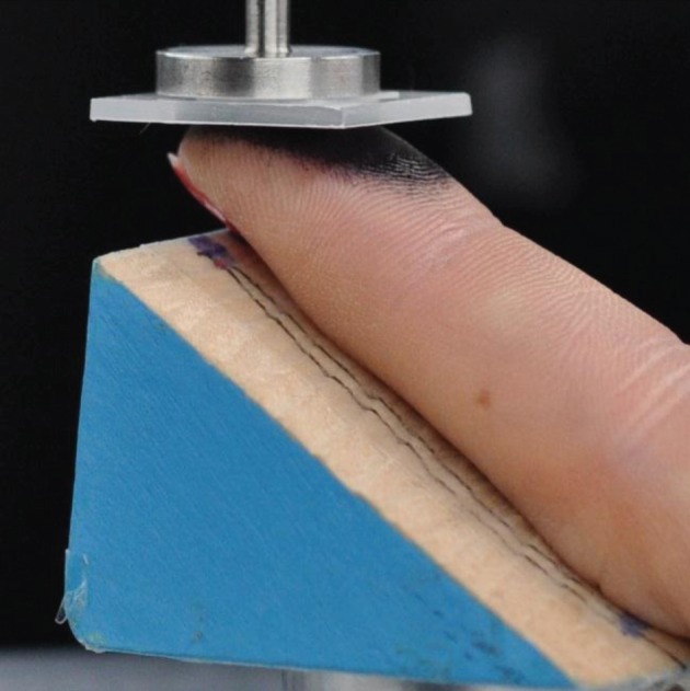
A photograph of the inked finger in contact with the compression platen resting on the 30° wedge support. (Online version in colour.)
2.3. Contact area
The finger pad was brought into contact with a rubber stamp pad (Dormy, no. 3) to apply a thin ink film. In the case of the contact area measurements, adhesive backed paper labels were attached to the glass plates. Finger pad compression was done using a cross-head velocity of 2 mm s−1 to 12 loads in the range 0.02–2 N; with a 2 s dwell at each maximum load prior to decompression and four ink prints being taken for each load. The ink prints were scanned, and the gross and ridge areas were determined using image analysis software (ImageJ, http://imagej.nih.gov/ij/).
3. Results
The mean radii of curvature calculated for the finger pad orientations of 30° and 45° were calculated to be 18.7 and 13.2 mm using the method described in §2.1.
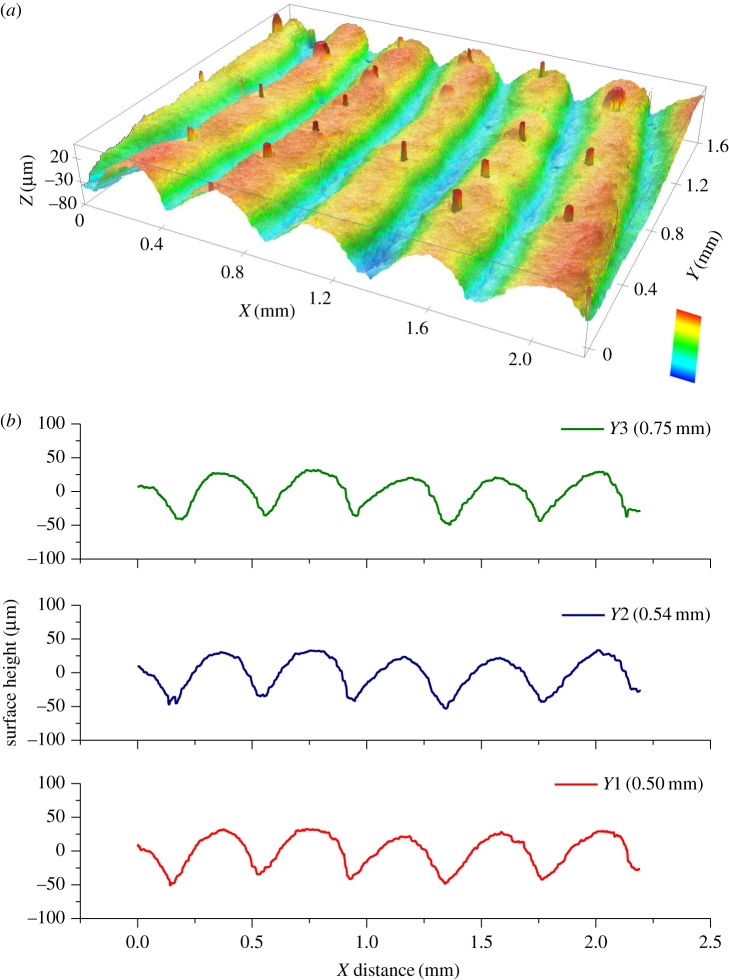
Figure 2 shows a typical three-dimensional profile of the fingerprint ridges and line scans that demonstrate the approximately circular cross section of the peaks of the ridges. The topography was characterized by fitting arcs of a circle with radius Rr and a centre-to-centre spacing of sRr. The values of Rr and s are 0.32 (±0.02) mm and 1.33 (±0.01), which corresponds to a mean centre-to-centre distance of 426 µm. A simple geometrical analysis gives the peak-to-valley height to be 81 µm  . Comparable data were reported in a recent study of 26 subjects for which the centre-to-centre distance was 458 ± 71 µm, and the peak-to-valley height was 102 ± 26 µm [37]. However, the authors did not comment on whether or not the ridges were cylindrically capped, and it is not obvious from the published image.
Figure 2.
(a) A three-dimensional rendering of the fingerprint geometry, where the curvature of the finger pad replica itself has been removed. The full range of the colour bar represents a height difference of 130 µm. (b) Typical line profiles extracted from (a) that exemplify the approximately circular cross section of the peaks of the ridges. (Online version in colour.)
The compressive force as a function of displacement, ξ, for a velocity of 8 mm s−1 and orientations of the finger pad of 30° and 45°, is shown in figure 3. The compressive displacement, ξ, is obtained from the displacement of the platen such that ξ = 0 corresponds to initial contact. The force at a given displacement is greater for the orientation of 45° compared with 30°, and it was relatively independent of the displacement velocity for the range examined.
Figure 3.
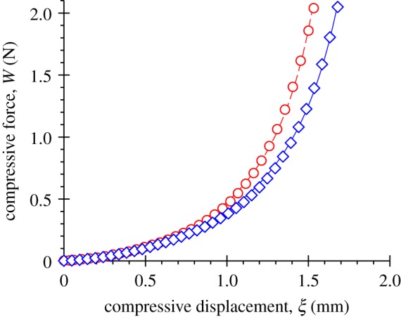
The compressive force, W, as a function of the imposed compressive displacement for a loading velocity of 8 mm s−1 corresponding to orientations of the finger pad of 30° (blue diamonds) and 45° (red circles). The full line (blue) and dashed line (red) are the best fits to equation (4.8) for 30° and 45° orientations respectively. (Online version in colour.)
Figure 4 exemplifies a typical finger print image obtained at a normal force of 2 N and orientation of 45°. Figure 5 shows the gross and ridge contact areas (mean and ± 1 s.d.), calculated from such images, as a function of the compressive force for orientations of the finger pad of 30° and 45°. The data were fitted to a power-law expression of the following form that was discussed in the introductory section:
| 3.1 |
where k and m are the load coefficient and load index, and m = mg and k = kg when A = Ag, and m = mr and k = kr when A = Ar. The best-fit values of these parameters are given in table 1.
Figure 4.
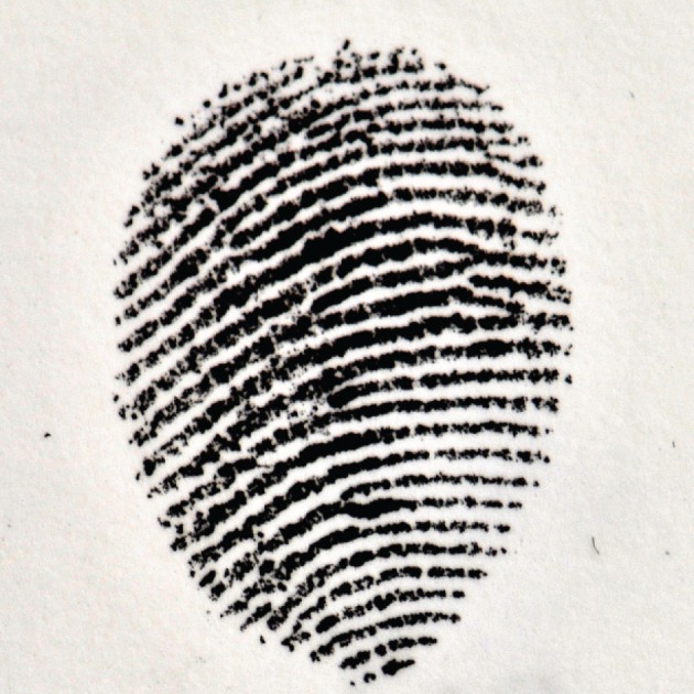
A typical fingerprint image obtained at a normal force of 2 N for a finger pad orientation of 45°.
Figure 5.
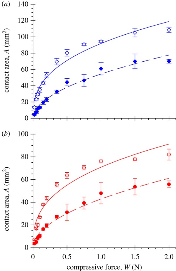
The gross finger pad (open points) and fingerprint ridge (filled points) contact areas as a function of the compressive force for orientations of the finger pad of (a) 30° and (b) 45°. The full and dashed lines are the best power-law fits to equation (3.1) for the gross and ridge areas respectively. (Online version in colour.)
Table 1.
Best-fit parameters of the contact area data (figure 5) to the power-law equation (3.1). The values given in parentheses are standard errors.
| orientation | W (N) |  |
mg |  |
mr |
|---|---|---|---|---|---|
| 30° | 2 | 91.9 (±2.7) | 0.37 (±0.03) | 54.4 (±1.7) | 0.52 (±0.04) |
| 45° | 2 | 70.9 (±2.9) | 0.36 (±0.04) | 42.9 (±1.2) | 0.51 (±0.03) |
Figure 6 shows experimental data for the gross contact area as a function of the compressive displacement for the two finger pad orientations; the maximum displacements correspond to a normal force of 2 N.
Figure 6.
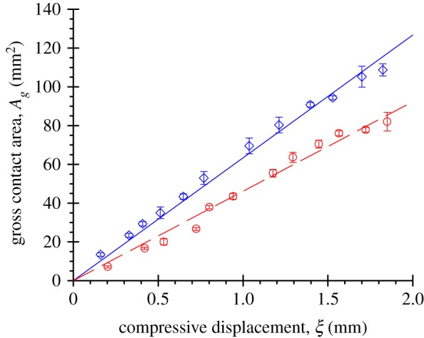
The gross contact area of the finger pad, Ag, as a function of the compressive displacement for orientations of the finger pad of 30° (blue diamonds) and 45° (red circles). The full line (blue) and dashed line (red) are the best straight line fits to equation (4.1) for 30° and 45° orientations, respectively, and used to obtain corresponding values for the mean finger pad radius of curvature, Rg. (Online version in colour.)
4. Discussion
The values of mg and mr given in table 1 are smaller than those reported by Soneda & Nakano [18] that were discussed previously; the values of k were not reported by these authors. While the ridge indices (ca 0.5) are slightly less than the Hertzian value (0.67), the gross values are much less (ca 0.35). An important feature of such data is they demonstrate that the contact area of the ridges increases with increasing normal load at a rate that is greater than that of the gross finger pad. This must arise, because the ridges deform under a compressive load as discussed previously. The quality of the power-law fits in figure 5 is relatively poor for the gross areas, which indicates that the data do not accurately fit a simple power law. An alternative model is described below that accounts for the constraint provided by the distal phalanx.
The loading curves measured here, examples of which are shown in figure 3, have a similar exponential form to those published previously in the velocity range 0.2–80 mm s−1 [31]. However, in this previous work, the data appeared to be much more rate dependent but a greater range of velocities was examined, and the trend was not entirely systematic, which suggests that there were some uncertainties in the data. To be consistent with the observed Hertzian parabolic radial pressure distribution [31], a finger pad also should exhibit Hertzian compliance as defined by the following expression [16]:
| 4.1 |
where Rg is the effective radius of the finger pad; i.e. the radius of a sphere with the equivalent compression/contact area relationship.
The best fits to this equation are shown in figure 6 for the two finger pad orientations. From the gradients, the mean values of Rg are calculated to be 20.5 ± 0.4 mm and 14.5 ± 0.4 mm for the orientations of 30° and 45°. They are less than 10% greater than those calculated from the undeformed geometry of the finger pad (R0 g = 18.7 and 13.4 mm), but this will inevitably involve some errors in fitting ellipses. In addition, as described in the electronic supplementary material, these values of the effective radii have to be corrected when applied to an ellipsoid, because the pressure distribution, and hence the displacements, are a function of the location on the perimeter of the elliptical contact region [16]. The corrected values are 19.9 and 14.0 mm, respectively, which is sufficiently similar to those obtained from the loading curves that it is reasonable to assume the Hertzian compliance relationship may be applied to the finger pad. Consequently, the radii from the compliance plots will be employed in subsequent calculations as being more representative of the measured contact mechanics.
4.1. Secant modulus and loading response
The Hertz equation for the loading of a finger pad in contact with a smooth rigid plane may be written in the following form [16]:
| 4.2 |
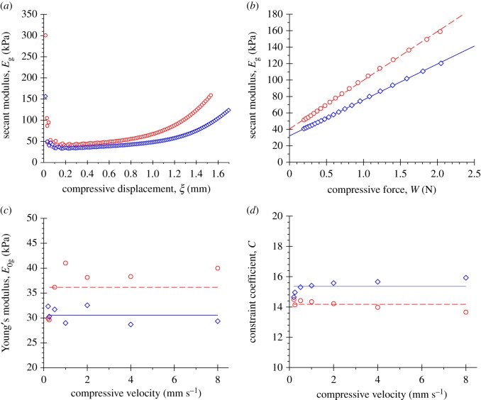
where the reduced elastic modulus is given by  such that Eg and vg are the elastic modulus and Poisson's ratio of the finger pad; the value of vg was taken to be 0.5 [22]. If the loading could be described by equation (4.2), then the modulus, Eg, would correspond to Young's modulus value, E0 g. However, because the loading is non-Hertzian (e.g. the data shown in figure 3 do not follow a power law with a displacement index of 3/2), Eg is a secant modulus but it might be expected that
  as W → 0. The secant modulus, Eg, calculated from the data obtained at a displacement velocity of 8 mm s−1 using equation (4.2) is plotted in figure 7a as a function of displacement for the orientations of 30° and 45°. The initial values are relatively large, approximately 300 kPa and rapidly decrease before gradually increasing. At small displacements, and hence at small contact radii, the upper layers of the skin will be sensed, because the maximum subsurface shear stress occurs at about 0.7ag for a Hertzian contact [16], where ag is the contact radius. Consequently, the stratum corneum will make a large contribution to the modulus but in a complicated way given the nature of the anatomical structure and surface topography of the finger pad. The region of increasing modulus would then correspond to deeper and softer layers nearer the bone. For displacements up to approximately 0.9 mm in the region of increasing modulus, the rate of increase is relatively small, so that it may be regarded as approximately Hertzian with a modulus of approximately 40 kPa. This was found to be the case in previous work, and the calculated Young's moduli for a group of male and female subjects were 59 ± 13 and 82 ± 20 kPa [37]. These values were calculated using the geometric mean of the radii of curvature with a value of 13.3 ± 3 mm. The angle of the finger pads was not stated but appeared to be comparable to approximately 30°. If this were the case, then the difference would be explained partly by the smaller radius of curvature.
Figure 7.
(a) The secant modulus, Eg, as a function of compressive displacement for a compressive velocity of 8 mm s−1 calculated from equation (4.2) for orientations of the finger pad of 30° (blue diamonds) and 45° (red circles). (b) The secant modulus, Eg, as a function of the compressive force. The data are taken from the increasing region of (a). The full line (blue) and dashed line (red) are the best straight line fits to equation (4.7) for 30° and 45° orientations respectively, and used to obtain corresponding values for the Young's modulus, E0 g, and the load coefficient of the secant modulus, β. (c) The Young's modulus, E0 g, as a function of the compressive velocity. The full line (blue) and dashed line (red) are the mean values for 30° and 45° orientations, respectively. (d) The constraint coefficient, C, as a function of the compressive velocity, as calculated from the values of β,  and Rg. The full line (blue) and dashed line (red) are the mean values for 30° and 45° orientations, respectively. (Online version in colour.)
In order to account for the constraint arising from the distal phalanx described previously, it was assumed that the relative change in the secant modulus was proportional to some power-law function of the strain as follows:
 |
4.3 |
such that  , where C is termed a constraint coefficient and ɛ is the strain. As is described below, it was found that the experimental data could most accurately be described with η = 3. Essentially, this is a consequence of the experimental observation that the secant modulus is a linear function of the load, as will be shown later in this section. The appropriate expression for the Hertzian strain [38] may be written as follows by substituting in equation (4.1) using
  :
:
 |
4.4 |
In the case of an ellipsoidal finger pad, both ag and Rg are the radii associated with the equivalent spherical contact.
Thus, from equations (4.3) and (4.4), the secant modulus may be written in the following form:
 |
4.5 |
The maximum displacement was approximately 1.6 mm, which corresponds to a maximum strain of approximately 0.066 according to equation (4.4) and thus satisfies the condition ɛ ≤ 1/C for equation (4.3). Strictly, the Hertz equation is only applicable to small strains but the limit is not clearly defined. However, in practice, it appears to fit experimental data to quite high strains; for example, maximum values of 0.08 [38] and approximately 0.3 [39] have been reported.
To derive an expression for the contact areas as a function of load, it is necessary to determine the influence of load on the secant modulus. Rearranging equation (4.5) yields
 |
4.6 |
Equations (4.2) and (4.6) lead to a linear relationship between  and W, as discussed previously
 |
4.7 |
where the load coefficient  . Figure 7b shows the secant modulus, Eg, as a function of the load for a displacement velocity of 8 mm s−1 and the orientations of 30° and 45°. Best-fit straight lines to the data yield values for E0 g and β and, hence, C. The values for E0 g and C are plotted as function of velocity in figure 7c, d, respectively. There does not appear to be a significant trend of these fitted parameters with increasing velocity. The mean values of E0 g are 30.6 and 36.2 kPa for orientations of the finger pad of 30° and 45°, which is similar to the value of 40 kPa measured for the inner forearm [10]. The mean values of C are 15.4 and 14.2 for orientations of the finger pad of 30° and 45°, whereas the corresponding mean values of β are 1.27 and 1.72 N−1. The mean values together with their standard deviations are given in table 2.
Table 2.
Geometric and mechanical parameters for the finger pad, as calculated using a fingerprint geometry given by Rr = 0.32 mm and s = 1.33, and with the assumption that νg = 0.5 and νr = 0.3. The values given in parentheses are standard errors for the best-fit parameters Rg (figure 6) and Er (figure 8b), and standard deviations for the mean parameters E0 g (figure 7c), C (figure 7d) and β.
| orientation | Rg (mm) | E0 g (kPa) | C | β (N−1) | Er (kPa) |
|---|---|---|---|---|---|
| 30° | 20.5 (±0.4) | 31 (±2) | 15.4 (±0.4) | 1.27 (±0.08) | 108 (±11) |
| 45° | 14.5 (±0.4) | 36 (±5) | 14.2 (±0.2) | 1.72 (±0.29) | 134 (±12) |
Equations (4.2) and (4.5) lead to the following loading relationship:
 |
4.8 |
The best fits of this equation to the data at a velocity of 8 mm s−1 are shown in figure 3. The compressive force at a given displacement is greater for the steeper orientation of 45° compared with 30° as a result of larger values of β and E0 g and, hence, of Eg, but not of C (figure 7 and table 2).
4.2. Gross contact area
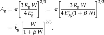
The gross contact area may be obtained by substitution of equation (4.7) in the appropriate form of the Hertz equations given by equations (4.1) and (4.2) [16]
 |
4.9 |
It is noted that the form of this equation is such that if β = 0 then the Hertz equation is recovered (n = 2/3), while if  , then Ag is load-independent (n = 0), which is the observed behaviour at large loads.
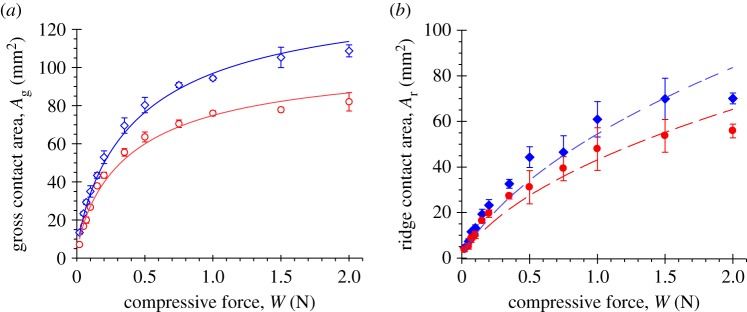
Figure 8a shows best fits of this equation using the values β (1.35 and 1.53 N−1) for the 30° and 45° orientations obtained for the same velocity as used for the contact area measurements; viz., 2 mm s−1. The smaller value of Rg for the data at the 45° orientation (14.5 mm) compared with that at 30° (20.5 mm) is the main cause of the smaller contact area at a given load, because the fitted values of  are similar (29 and 28 kPa for 30° and 45° respectively, which are similar to the values obtained from the secant modulus analysis in §4.1). By comparing the curves in figures 5 and 8a, it may be seen that equation (4.9) is more accurate than a simple power law in fitting the Ag data over the whole load range.
Figure 8.
(a) The gross contact area, Ag, as a function of the compressive force for orientations of the finger pad of 30° (blue diamonds) and 45° (red circles); the data are taken from figure 5. The upper (blue) and lower (red) lines are for the 30° and 45° orientations, respectively, and represent best fits to equation (4.9) using the corresponding values of Rg (table 2) and values of β of 1.35 and 1.53 N−1 (which are the best-fit values obtained for a compressive velocity of 2 mm s−1). The fitted values of the Young's modulus, E0 g (±1 s.e.) are 28.6 ± 0.3 kPa and 27.7 ± 0.5 kPa for the 30° and 45° orientations, respectively (assuming νg = 0.5). (b) The fingerprint ridge contact area, Ar, as a function of the compressive force; the data are taken from figure 5. The upper (blue) and lower (red) dashed lines for 30° and 45° orientations, respectively, are best fits to equation (4.10) using the same values of β and E0 g used for (a). The fitted values of Er (±1 s.e.) are 108 ± 11 and 134 ± 12 kPa, assuming that s = 1.33 and νr = 0.3. (Online version in colour.)
4.3. Ridge contact area
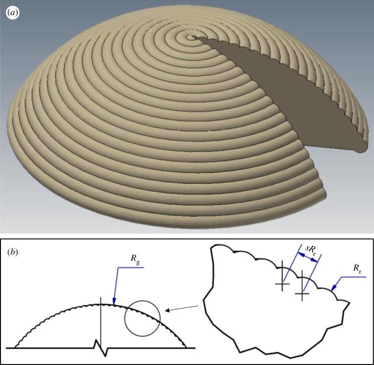
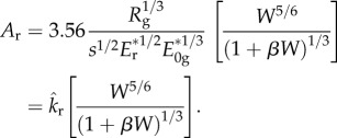
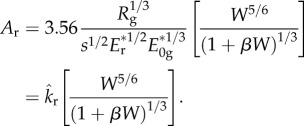
The ridge contact area as a function of load may be obtained by an elastic contact analysis of the geometry shown schematically in figure 9. This analysis is described in appendix B, and leads to the following expression (equation B 9):
 |
4.10 |
It is noted that the values of Ar calculated from this equation are nominal ridge contact areas, because the model assumes the ridges are both smooth and continuous and ignores their surface texture. The form of the equation is such that the load index can range between n = 0.83 (β = 0) and n = 0.5 ( ), which is within the range deduced through friction measurements for the fully occluded state [15].
Figure 9.
Schematic diagram (a) of a spherically capped finger pad of radius Rg with cylindrically capped concentric fingerprint ridges of radius Rr and spacing sRr between their centres as shown in (b). (Online version in colour.)
4.4. Ridge elastic modulus
The measured nominal contact areas of the fingerprint ridges are plotted as a function of load in figure 8b and show the best fits of equation (4.10) to the data. The values of Er obtained from the fittings are 108 (±11) and 134 (±12) kPa for the orientations of 30° and 45°. The fits are less accurate at the highest loads and this may arise from the variability associated with using ink prints to calculate the ridge areas, or deficiencies in the simple geometric model used in the elastic contact analysis. That the values are approximately independent of the orientation of the finger pad within experimental error, as should be the case, provides some support for the validity of the model. However, the values are considerably smaller than the range of 1–1000 MPa typically reported for the Young's modulus of stratum corneum [40,41]; the large range arises partly from the sensitivity to the nominal moisture levels and strain rates at which the measurements are made. Generally, for ex vivo samples, such values are obtained by tensile measurements, which may behave differently from in vivo stratum corneum, and is associated with experimental uncertainties such as eliminating the natural crimping. In vivo indentation measurements are complicated by the multilayer structure of skin and the underlying tissues, and the through-thickness moisture gradient. Consequently, the results depend on the indenter geometry and indentation depth [40] and the model used to interpret the data. Thus, the reported Young's moduli are essentially ill-defined mean values over the stress field of the subsurface volume on which the indenter acts.
Dynamic optical coherence elastography is a much more direct method for measuring the in vivo biomechanical properties of skin, because the spatial resolution and directionality are clearly defined. Using this technique, Liang et al. [42] have reported values of the Young's modulus in the range 23–300 kPa depending on the hydration state of the stratum corneum and the applied frequency. The current values are within this range and thus provide further evidence of the reliability of the model. More conclusively, the current values of the ridge modulus are only about a factor of three greater than those of the gross finger pad at small strains and are comparable at larger strains. If the ridge modulus was much greater, then the ridge deformation under the action of a normal force may be insufficient to account for both the observed ridge contact area and the frictional behaviour.
4.5. Rate dependence
The application of a linear elastic model of the finger pad that is homogeneous and isotropic but is constrained by the distal phalanx is consistent with the loading behaviour and the gross and nominal contact areas of the fingerprint ridges. Phillips & Johnson [43,44] established the value of such models, but without constraint, by the close agreement between the calculated strains arising from the contact with gratings and the measured response of one type of mechanoreceptor (SAI) that innervates the finger pad. However, clearly it is not possible to determine accurately the subsurface stress field with this approach, because the structure of finger pad involves two outer layers of skin comprising the epidermis and dermis and an inner region of biphasic fat and water in addition to the distal phalanx. The deformation of the skin is viscoelastic and anisotropic [45], and it is probable that the fatty component will be poroelastic with a Poisson's ratio that is a function of strain. Pawluk & Howe [29,31] have established that the deformation of the finger pad is rate dependent but, for the range of displacement velocities examined here, the behaviour appears to be approximately steady state even though the deformation time at the highest velocity exceeds the relaxation time determined by these authors. They also demonstrated that the separation of the strain and strain rate is a viable strategy for deriving analytical solutions of the contact mechanics. For example, incorporating the strain rate dependence is critical for understanding the performance of flat-screen haptic displays based on vibration at ultrasonic frequencies [8].
5. Conclusion
An analytical elastic contact model, based on a geometrical simplification of the finger pad and the fingerprint ridges and a secant modulus that is linearly proportional to the load, gives expressions for the gross and ridge contact areas as a function of load. They are consistent with experimental contact area data obtained both directly from ink print images and indirectly from friction measurements of a finger pad against smooth surfaces. The Young's modulus of the ridges calculated from the experimental data using this model is considerably less than the wide range of reported values of stratum corneum using mechanical measurements even at high water activities. This finding is consistent with values obtained more directly using dynamic optical coherence elastography. Moreover, the current values are of the order of that for the gross finger pad, and this is essential for there to be sufficient deformation to account for both the ridge contact area and the frictional behaviour. This also highlights the difficulty of obtaining and interpreting the Young's modulus from mechanical measurements.
The model is limited to the fully occluded state where it is reasonable to assume that the fingerprint ridges make complete contact with the surface owing to the plasticization induced by the secretion of moisture as sweat. In the initial and partially occluded states, it will be necessary to account for the influence of the topography of the ridge surfaces that are not completely flattened owing to the limited plasticization [46]. However, in these states, the model may still be used to calculate the gross contact area.
Supplementary Material
Appendix A. Nomenclature
| symbol | description | units |
|---|---|---|
| ag | equivalent contact radius of the finger pad 
|
m |
| ar | semi-contact width of fingerprint ridge | m |
| k | power-law load coefficient for contact area | m2 N−m |
| kf | load-dependent coefficient of friction | m2 N−n |
| kg | power-law load coefficient for finger pad gross contact area | m2 N−mg |
 |
load coefficient for finger pad gross contact area | m2 N−2/3 |
| kr | power-law load coefficient for fingerprint ridge contact area |  |
 |
load coefficient for fingerprint ridge contact area | m2 N−5/6 |
 |
semi-axis to palmar face of finger pad ellipsoid | m |
 |
semi-axis to distal face of finger pad ellipsoid | m |
 |
semi-axis to ulnar/radial faces of finger pad ellipsoid | m |
| m | power-law load index for contact area | |
| mg | power-law load index for finger pad gross contact area | |
| mr | power-law load index for fingerprint ridge contact area | |
| n | power-law load index for frictional force | |
| p | mean contact pressure = W/A | Pa |
| pg(r) | finger pad pressure radial distribution | Pa |
| q | number of fingerprint ridges in an annulus of width δr | |
| r | radial coordinate from contact centre | m |
| s | fingerprint ridge spacing factor | |
| u | palmar axis angular coordinate of point on finger pad ellipsoid | rad |
| v | radial axis angular coordinate of point on finger pad ellipsoid | rad |
| w | fingerprint ridge load per unit length | Nm−1 |
| x | palmar coordinate of point on finger pad ellipsoid | m |
| y | distal coordinate of point on finger pad ellipsoid | m |
| z | ulnar/radial coordinate of point on finger pad ellipsoid | m |
| A | contact area | m2 |
| Ag | finger pad gross contact area | m2 |
| Ar | fingerprint ridge contact area | m2 |
 |
contact area of a fingerprint ridge at radius r in region δθ | m2 |
| C | constraint coefficient for secant modulus | |
| Eg | secant modulus of the finger pad | Pa |
 |
reduced secant modulus of the finger pad 
|
Pa |
| E0 g | Young's modulus of the finger pad | Pa |
 |
reduced Young's modulus of the finger pad 
|
Pa |
| Er | elastic modulus of the fingerprint ridge | Pa |
 |
reduced elastic modulus of the fingerprint ridge 
|
Pa |
| F | friction force | N |
| H0 g | mean curvature of the finger pad ellipsoid | m−1 |
| Rg | effective radius of the finger pad | m |
| R0 g | mean radius of curvature of the finger pad ellipsoid | m |
| Rr | radius of cylindrically capped fingerprint ridge | m |
| W | normal force | N |
| α | pressure coefficient of interfacial shear strength | |
| β | load coefficient for secant modulus | N−1 |
| ɛ | compressive Hertzian strain | |
| η | strain index for secant modulus | |
| θ | angular coordinate about contact centre | rad |
| μ | coefficient of friction = F/W | |
| νg | Poisson's ratio of the finger pad | |
| νr | Poisson's ratio of the fingerprint ridge | |
| ξ | compressive displacement | m |
| τ | interfacial shear strength | Pa |
| τ0 | intrinsic interfacial shear strength (at p = 0) | Pa |
Appendix B. Ridge contact area
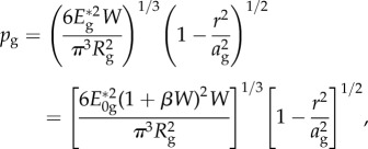
In order to calculate the nominal contact area of the ridges, the finger pad was simplified to a spherical cap of radius Rg with concentric cylindrically capped fingerprint ridges of radius Rr and spacing sRr between their centres as shown schematically in figure 9, which is consistent with the topographical data shown in figure 2. It is clear from figure 4 that the contact is non-circular, but the spherical cap model is assumed to be an equivalent axisymmetric point contact. It is also assumed that the spherical cap is compressed along its axis of symmetry against a smooth rigid platen, irrespective of the orientation of the finger pad, which is accounted for by the equivalent radius of curvature. The expression for the Hertzian radial pressure distribution [16] is modified by incorporating the load dependence of the modulus given by equation (4.7) as follows:
 |
B 1 |
where r is a radial coordinate with an origin at the centre and in the plane of the platen. In practice, the radial pressure distribution will be lumpy, rather than a smooth parabolic Hertzian profile, owing to the presence of the fingerprint ridges. However, the relative contribution of the ridges will decay with increasing normal load as Rr/ag → 0. Consequently, a first-order approximation of the load carried by any ridge may be calculated from equation (B 1) by ignoring the influence on the pressure distribution.
The load acting on a control area  is given by
 |
B 2 |
where θ is the angular coordinate.
The number of ridges, q, in an annulus of width δr is given by
| B 3 |
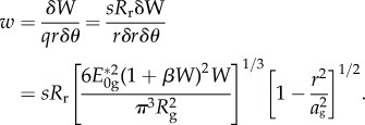
The load per unit length, w, acting on each ridge in the control area is given by
 |
B 4 |
It is assumed that a fingerprint ridge is linear elastic with an elastic modulus Er and Poisson's ratio νr = 0.3 [41], so that it acts as a Hertzian line contact under a load w per unit length. The semi-contact width, ar, can then be obtained from the following expression [16]:
 |
B 5 |
Consequently, the contact area,  , for each ridge in a region δθ can be derived from equations (B 4) and (B 5)
 |
B 6 |
The nominal ridge area of contact in a control area  is given by
| B 7 |
Substituting equation (B 6) in (B 7) and integrating with the limits r = 0, ag and θ = 0, 2π yields
 |
B 8 |
Finally, equations (4.9) and (B 8) give
 |
B 9 |
Ethics
The experimental protocols adopted for in vivo finger compression were approved by the local ethics committee, and the subject provided informed consent.
Data accessibility
The parameters given in the tables are obtained from experimental data shown in the figures. They can be used to generate the fitted curves shown in the figures, and enable comparisons to be obtained with past or future experiments.
Authors' contributions
B.M.D. and M.J.A. designed and coordinated the study and drafted the manuscript; B.M.D. and S.A.J. performed the experiments and conducted the data analysis; J.W.A. and Z.Z. participated in the statistical analysis and contact modelling. All authors made substantial contributions to the critical revision of the submitted manuscript.
Competing interests
The authors do not have competing interests.
Funding
This work was supported by the FP7 Marie Curie Initial Training Network PROTOTOUCH, grant agreement no. 317100.
References
- 1.Adams MJ, Johnson SA, Lefèvre P, Lévesque V, Hayward V, André T, Thonnard J-L. 2013. Finger pad friction and its role in grip and touch. J. R. Soc. Interface 10, 20120467 ( 10.1098/rsif.2012.0467) [DOI] [PMC free article] [PubMed] [Google Scholar]
- 2.Friedman RM, Hester KD, Green BG, LaMotte RH. 2008. Magnitude estimation of softness. Exp. Brain Res. 191, 133–142. ( 10.1007/s00221-008-1507-5) [DOI] [PMC free article] [PubMed] [Google Scholar]
- 3.Condon M, Birznieks I, Hudson K, Chelvanayagam DK, Mahns D, Olausson H, Macefield VG. 2014. Differential sensitivity to surface compliance by tactile afferents in the human finger pad. J. Neurophysiol. 111, 1308–1317. ( 10.1152/jn.00589.2013) [DOI] [PubMed] [Google Scholar]
- 4.Hudson KM, Condon M, Ackerley R, McGlone F, Olausson H, Macefield VG, Birznieks I. 2015. Effects of changing skin mechanics on the differential sensitivity to surface compliance by tactile afferents in the human finger pad. J. Neurophysiol. 114, 2249–2257. ( 10.1152/jn.00176.2014) [DOI] [PMC free article] [PubMed] [Google Scholar]
- 5.André T, Lefèvre P, Thonnard J-L. 2010. Fingertip moisture is optimally modulated during object manipulation. J. Neurophysiol. 103, 402–408. ( 10.1152/jn.00901.2009) [DOI] [PubMed] [Google Scholar]
- 6.André T, Lévesque V, Hayward V, Lefèvre P, Thonnard J-L. 2011. Effect of skin hydration on the dynamics of fingertip gripping contact. J. R. Soc. Interface 8, 1574–1583. ( 10.1098/rsif.2011.0086) [DOI] [PMC free article] [PubMed] [Google Scholar]
- 7.Sednaoui T, Vezzoli E, Dzidek B, Lemaire-Semail B, Chappaz C, Adams MJ. 2015. Experimental evaluation of friction reduction in ultrasonic devices. In Proc. IEEE World Haptics Conf., Chicago, USA, 22–26 June 2015, pp. 37–42 ( 10.1109/WHC.2015.7177688) [DOI] [PubMed]
- 8.Vezzoli E, Dzidek B, Sednaoui T, Giraud F, Adams MJ, Lemaire-Semail B. 2015. Role of fingerprint mechanics and non-Coulombic friction in ultrasonic devices. In Proc. IEEE World Haptics Conf., Chicago, USA, 22–26 June 2015, pp. 43–48 ( 10.1109/WHC.2015.7177689) [DOI]
- 9.Bowden FP, Tabor D. 1954. Friction and lubrication of solids. Oxford, UK: Clarendon Press. [Google Scholar]
- 10.Adams MJ, Briscoe BJ, Johnson SA. 2007. Friction and lubrication of human skin. Tribol. Lett. 26, 239–253. ( 10.1007/s11249-007-9206-0) [DOI] [Google Scholar]
- 11.Derler S, Preiswerk M, Rotaru GM, Kaiser JP, Rossi RM. 2015. Friction mechanisms and abrasion of the human finger pad in contact with rough surfaces. Tribol. Int. 89, 119–127. ( 10.1016/j.triboint.2014.12.023) [DOI] [Google Scholar]
- 12.Tomlinson SE, Carré MJ, Lewis R, Franklin SE. 2011. Human finger contact with small, triangular ridged surfaces. Wear 271, 2346–2353. ( 10.1016/j.wear.2010.12.055) [DOI] [Google Scholar]
- 13.Tomlinson SE, Lewis R, Carre MJ, Franklin SE. 2013. Human finger friction in contacts with ridged surfaces. Wear 301, 330–337. ( 10.1016/j.wear.2012.12.039) [DOI] [Google Scholar]
- 14.Pasumarty SM, Johnson SA, Watson SA, Adams MJ. 2011. Friction of the human finger pad: influence of moisture, occlusion and velocity. Tribol. Lett. 44, 117–137. ( 10.1007/s11249-011-9828-0) [DOI] [Google Scholar]
- 15.Dzidek BM, Adams M, Zhang Z, Johnson S, Bochereau S, Hayward V. 2014. Role of occlusion in non-Coulombic slip of the finger pad. In Haptics: neuroscience, devices, modeling, and applications, part 1, pp. 109–116. Berlin, Germany: Springer; ( 10.1007/978-3-662-44193-0_15) [DOI] [Google Scholar]
- 16.Johnson KL. 1985. Contact mechanics. Cambridge, UK: Cambridge University Press. [Google Scholar]
- 17.van Kuilenburg J, Masen MA, van der Heide E. 2015. A review of fingerpad contact mechanics and friction and how this affects tactile perception. Proc. IMechE Part J, J. Eng. Tribol. 229, 243–258. ( 10.1177/1350650113504908) [DOI] [Google Scholar]
- 18.Soneda T, Nakano K. 2010. Investigation of vibrotactile sensation of human fingerpads by observation of contact zones. Tribol. Int. 43, 210–217. ( 10.1016/j.triboint.2009.05.016) [DOI] [Google Scholar]
- 19.Warman PH, Ennos AR. 2009. Fingerprints are unlikely to increase the friction of primate fingerpads. J. Exp. Biol. 212, 2016–2022. ( 10.1242/jeb.028977) [DOI] [PubMed] [Google Scholar]
- 20.Lin H-T, Hong T-F, Li W-L. 2015. Grip performance affected by water-induced wrinkling of fingers. Tribol. Lett. 58, 38 ( 10.1007/s11249-015-0515-4) [DOI] [Google Scholar]
- 21.Liu X, Lu Z, Lewis R, Carré MJ, Matcher SJ. 2013. Feasibility of using optical coherence tomography to study the influence of skin structure on finger friction. Tribol. Int. 63, 34–44. ( 10.1016/j.triboint.2012.08.020) [DOI] [Google Scholar]
- 22.Srinivasan MA, Dandekar K. 1996. An investigation of the mechanics of tactile sense using two-dimensional models of the primate fingertip. J. Biomech. Eng. 118, 48–55. ( 10.1115/1.2795945) [DOI] [PubMed] [Google Scholar]
- 23.Dandekar K, Raju BI, Srinivasan MA. 2003. 3-D finite-element models of human and monkey fingertips to investigate the mechanics of tactile sense. J. Biomech. Eng. 125, 682–691. ( 10.1115/1.1613673) [DOI] [PubMed] [Google Scholar]
- 24.Wu JZ, Dong RG, Rakheja S, Schopper AW, Smutz WP. 2004. A structural fingertip model for simulating of the biomechanics of tactile sensation. Med. Eng. Phys. 26, 165–175. ( 10.1016/j.medengphy.2003.09.004) [DOI] [PubMed] [Google Scholar]
- 25.Wu JZ, Welcome DE, Dong RG. 2006. Three-dimensional finite element simulations of the mechanical response of the fingertip to static and dynamic compressions. Comp. Meth. Biomech. Biomed. Eng. 9, 55–63. ( 10.1080/10255840600603641) [DOI] [PubMed] [Google Scholar]
- 26.Shao F, Childs THC, Barnes CJ, Henson B. 2010. Finite element simulations of static and sliding contact between a human fingertip and textured surfaces. Tribol. Int. 43, 2308–2316. ( 10.1016/j.triboint.2010.08.003) [DOI] [Google Scholar]
- 27.Hu J, Ding X, Wang R. 2010. Effect of fingerpad mechanics and anatomical structures on tactile detection of compliant objects. In Proc. IEEE 6th Int. Conf. on Natural Computation, Yantai, China, 10–12 August 2010, pp. 2097–2101 ( 10.1109/ICNC.2010.5582435) [DOI]
- 28.Somer DD, Perić D, de Souza Neto EA, Dettmer WG. 2015. A multi-scale computational assessment of channel gating assumptions within the Meissner corpuscle. J. Biomech. 48, 73–80. ( 10.1016/j.jbiomech.2014.11.003) [DOI] [PubMed] [Google Scholar]
- 29.Pawluk DT, Howe RD. 1999. Dynamic contact of the human fingerpad against a flat surface. J. Biomech. Eng. 121, 605–611. ( 10.1115/1.2800860) [DOI] [PubMed] [Google Scholar]
- 30.Fung YC. 1993. Biomechanics: mechanical properties of living tissues. New York, NY: Springer. [Google Scholar]
- 31.Pawluk DT, Howe RD. 1999. Dynamic lumped element response of the human fingerpad. J. Biomech. Eng. 121, 178–183. ( 10.1115/1.2835100) [DOI] [PubMed] [Google Scholar]
- 32.Jindrich DL, Zhou Y, Becker T, Dennerlein JT. 2003. Non-linear viscoelastic models predict fingertip pulp force-displacement characteristics during voluntary tapping. J. Biomech. 36, 497–503. ( 10.1016/S0021-9290(02)00438-4) [DOI] [PubMed] [Google Scholar]
- 33.Derler S, Gerhardt L-C, Lenz A, Bertaux E, Hadad M. 2009. Friction of human skin against smooth and rough glass as a function of the contact pressure. Tribol. Int. 42, 1565–1574. ( 10.1016/j.triboint.2008.11.009) [DOI] [Google Scholar]
- 34.Hsueh CH, Miranda P. 2004. Master curves for Hertzian indentation on coating/substrate systems. J. Mater. Res 19, 94–100. ( 10.1557/jmr.2004.19.1.94) [DOI] [Google Scholar]
- 35.Zahouani H, Mezghani S, Vargiolu R, Hoc T, Mansori ME. 2013. Effect of roughness on vibration of human finger during a friction test. Wear 301, 343–352. ( 10.1016/j.wear.2012.11.028) [DOI] [Google Scholar]
- 36.Duvefelt K, Olofsson U, Johannesson CM, Skedung L. 2014. Model for contact between finger and sinusoidal plane to evaluate adhesion and deformation component of friction. Tribol. Int. 96, 389–394. ( 10.1016/j.triboint.2014.12.020) [DOI] [Google Scholar]
- 37.Cornuault PH, Carpentier L, Bueno MA, Cote JM, Monteil G. 2015. Influence of physico-chemical, mechanical and morphological fingerpad properties on the frictional distinction of sticky/slippery surfaces. J. R. Soc. Interface 12, 20150495 ( 10.1098/rsif.2015.0495) [DOI] [PMC free article] [PubMed] [Google Scholar]
- 38.Lin DC, Shreiber DI, Dimitriadis EK, Horkay F. 2009. Spherical indentation of soft matter beyond the Hertzian regime: numerical and experimental validation of hyperelastic models. Biomech. Model. Mechanobiol. 8, 345–358. ( 10.1007/s10237-008-0139-9) [DOI] [PMC free article] [PubMed] [Google Scholar]
- 39.Yan Y, Zhang Z, Stokes JR, Zhou QZ, Ma GH, Adams MJ. 2009. Mechanical characterization of agarose micro-particles with a narrow size distribution. Powder Technol. 192, 122–130. ( 10.1016/j.powtec.2008.12.006) [DOI] [Google Scholar]
- 40.van Kuilenburg J, Masen MA, van der Heide E. 2013. Contact modelling of human skin: what value to use for the modulus of elasticity? Proc. IMechE Part J, J. Eng. Tribol. 227, 349–361. ( 10.1177/1350650112463307) [DOI] [Google Scholar]
- 41.Leyva-Mendivil MF, Page A, Bressloff NW, Limbert G. 2015. A mechanistic insight into the mechanical role of the stratum corneum during stretching and compression of the skin. J. Mech. Behav. Biomed. Mater. 49, 197–219. ( 10.1016/j.jmbbm.2015.05.010) [DOI] [PubMed] [Google Scholar]
- 42.Liang X, Boppart SA. 2010. Biomechanical properties of in vivo human skin from dynamic optical coherence elastography. IEEE Trans. Biomed. Eng. 57, 953–959. ( 10.1109/TBME.2009.2033464) [DOI] [PMC free article] [PubMed] [Google Scholar]
- 43.Johnson KO, Phillips JR. 1981. Tactile spatial resolution. I. Two-point discrimination, gap detection, grating resolution, and letter recognition. J. Neurophysiol. 46, 1177–1192. [DOI] [PubMed] [Google Scholar]
- 44.Phillips JR, Johnson KO. 1981. Tactile spatial resolution. II. Neural representation of bars, edges, and gratings in monkey primary afferents. J. Neurophysiol. 46, 1192–1203. [DOI] [PubMed] [Google Scholar]
- 45.Wang Q, Hayward V. 2007. In vivo biomechanics of the fingerpad skin under local tangential traction. J. Biomech. 40, 851–860. ( 10.1016/j.jbiomech.2006.03.004) [DOI] [PubMed] [Google Scholar]
- 46.Dzidek BM, Adams M, Johnson S, Bochereau S, Hayward V. 2016. Frictional dynamics of finger pads are governed by four length-scales and two time-scales. Proc. IEEE Haptics Symp., Philadelphia, PA, USA, 8–11 April 2016, pp. 161–166. ( 10.1109/HAPTICS.2016.7463171) [DOI] [Google Scholar]
Associated Data
This section collects any data citations, data availability statements, or supplementary materials included in this article.
Supplementary Materials
Data Availability Statement
The parameters given in the tables are obtained from experimental data shown in the figures. They can be used to generate the fitted curves shown in the figures, and enable comparisons to be obtained with past or future experiments.


