Abstract
Nitrogen doping opens possibilities for tailoring the electronic properties and band gap of graphene toward its applications, e.g., in spintronics and optoelectronics. One major obstacle is development of magnetically active N-doped graphene with spin-polarized conductive behavior. However, the effect of nitrogen on the magnetic properties of graphene has so far only been addressed theoretically, and triggering of magnetism through N-doping has not yet been proved experimentally, except for systems containing a high amount of oxygen and thus decreased conductivity. Here, we report the first example of ferromagnetic graphene achieved by controlled doping with graphitic, pyridinic, and chemisorbed nitrogen. The magnetic properties were found to depend strongly on both the nitrogen concentration and type of structural N-motifs generated in the host lattice. Graphenes doped below 5 at. % of nitrogen were nonmagnetic; however, once doped at 5.1 at. % of nitrogen, N-doped graphene exhibited transition to a ferromagnetic state at ∼69 K and displayed a saturation magnetization reaching 1.09 emu/g. Theoretical calculations were used to elucidate the effects of individual chemical forms of nitrogen on magnetic properties. Results showed that magnetic effects were triggered by graphitic nitrogen, whereas pyridinic and chemisorbed nitrogen contributed much less to the overall ferromagnetic ground state. Calculations further proved the existence of exchange coupling among the paramagnetic centers mediated by the conduction electrons.
Introduction
The successful isolation of individual layers of graphene in 20041 has triggered an intense interest in its unique structural and electronic properties.2 A very high carrier mobility along with weak spin–orbit and hyperfine interactions predestinates graphene as a promising material for spintronics, mainly if magnetic ordering can be introduced.3 However, due to the delocalized π bonding network, ideal graphene is intrinsically nonmagnetic. Therefore, developing effective methods for synthesizing ferromagnetic (FM) graphene with high magnetization is vital for applications in novel spintronic devices combining charge and spin manipulation. A number of factors including atomic vacancies, zigzag edges, sp3 functionalization, and chemical doping of foreign atoms can induce localized magnetic moments in graphene, which are indispensable for the existence of magnetic ordering.4−10 Among these strategies, doping of the graphene lattice with noncarbon atoms has been identified as a promising approach for imprinting magnetic ordering into graphene while preserving/enhancing its electric/optical properties, as desirable for spintronic, optoelectronic, and magnetooptical applications.
Substitutional doping of graphene by light elements has recently attracted much attention (see, e.g., refs (11−14)). In particular, nitrogen doping of the graphene lattice has been extensively studied, aimed at tuning the graphene electronic features, and hence its physical properties, in order to meet the requirements of a given application. N-doped graphenes have been tested as active materials for Li-ion batteries,15 fuel cells,12 field-effect transistors,16 ultra- and supercapacitors,17,18 and in the fields of photocatalysis19 and electrochemical biosensing.20 Chaban and Prezhdo have argued21 that graphene structures containing 1/3 of nitrogen atoms or less should be stable up to 1000 K provided N–N bonds, which impair the stability, are not formed. Having similar atomic size and one additional electron compared to a carbon atom, nitrogen acts as an n-type (electron-donating) dopant by increasing the number of electrons when substituted into the graphene lattice, thus affecting the graphene electric conductivity. The substitution of carbon by nitrogen atoms in the graphene lattice necessarily leads to changes in the electronic density of states, and graphitic nitrogen can provide π electrons close to the Fermi level of graphene. If the itinerant electrons occupy narrow bands at the Fermi level, Stoner magnetism can emerge, as recently shown for graphene doped with sulfur.22 Indeed, it has been theoretically proposed9 that depending on the concentration and packing geometry of doping nitrogen atoms, it is possible to induce a magnetic response in graphene. However, the physical mechanism governing the emergence of magnetically ordered structures was not discussed. Until now, all the experimental attempts to imprint magnetism into graphene through N-doping have failed. Recently, a detailed theoretical and experimental magnetic study revealed that introduction of pyrrolic nitrogen into the graphene lattice decreases the magnetization values compared to those observed for defective graphene.10 In contrast, pyrrolic nitrogen (at a concentration of 6.02 at. %) was identified to enhance ferromagnetism in highly oxidized graphene (i.e., graphene oxide) synthesized via hydrothermal reaction.23 FM behavior has also been reported in other nitrogen-doped graphene oxide systems.24 However, N-doped graphene oxides are unsatisfactory because a high amount of oxygen (sp3 functionalization) is regarded as a dominant source of magnetism, overwhelming the effects of nitrogen doping itself. Moreover, oxygen-containing functional groups drastically reduce the electric conductivity of graphene–the main prerequisite for spintronic technologies. Thus, development of FM N-doped graphene with negligible oxygen content and elucidation of the effect of various nitrogen configurations (pyrrolic, pyridinic, graphitic, chemisorbed) remains a key challenge in the fields of nanotechnologies, magnetism, and spintronics.10,25,26
In this work, we first report the emergence of a magnetically ordered state in graphene doped solely with nitrogen. When the substitutional level exceeded ∼5 at. % of nitrogen, the doping-induced paramagnetic centers commenced to interact magnetically, resulting in establishment of FM ordering at temperatures below ∼69 K. In the FM state, the saturation magnetization reached ∼1.09 emu/g, which is among the highest values reported so far for doped graphene-based systems. DFT calculations demonstrated that graphitic nitrogen was dominantly responsible for evolution of the magnetically active configurations. In contrast, pyridinic and chemisorbed nitrogen had a considerably lower effect on imprinting the magnetism into graphene. This finding opens possibilities for an extensive research in spintronic and magnetooptical technologies based on graphitic N-doped graphene.
Experimental Section
Materials
Graphite microparticles (2–15 μm, 99.9995%, Alfa Aesar) were used for all syntheses. Sulfuric acid (98%), nitric acid (68%), potassium chlorate (99%), hydrochloric acid (37%), silver nitrate (99.5%), and barium nitrate (99.5%) were obtained from Penta, Czech Republic. Nitrogen (99.9999% purity) and ammonia (99.9995% purity) were obtained from SIAD, Czech Republic.
Synthesis of Graphite Oxide
Graphite oxide was prepared according to the Hofmann method. Briefly, sulfuric acid (98%, 87.5 mL) and nitric acid (68%, 27 mL) were added to a reaction flask (Pyrex beaker with thermometer) containing a magnetic stir bar. The mixture was cooled by immersion in an ice bath for 30 min. Graphite (5 g) was then added to the mixture under vigorous stirring and, keeping the reaction flask in the ice bath, potassium chlorate (55 g) was slowly added. After a complete dissolution of potassium chlorate, the reaction flask was loosely capped to allow the escape of gas evolved and the mixture was continuously stirred for 96 h at room temperature. The mixture was poured into 3 L of deionized water and decanted. The obtained graphene oxide was then redispersed in HCl solution (5%, 3 L) to remove sulfate ions and repeatedly centrifuged and redispersed in deionized water until a negative reaction on chloride and sulfate ions with silver and barium nitrate was achieved. The resulting graphite oxide was dried in a vacuum oven at 50 °C for 48 h.
Synthesis of N-Doped Graphenes and Undoped Graphene
Nitrogen-doped graphenes were prepared by combined exfoliation and reduction of graphite oxide in an ammonia atmosphere. Briefly, 100 mg of graphite oxide was placed inside a quartz glass capsule connected to a magnetic manipulator and mounted in a horizontal quartz glass reactor. The reactor was repeatedly evacuated and flushed with nitrogen followed by ammonia. Subsequently, the sample was inserted in the hot zone of the reactor while the ammonia flow was kept at 1000 mL min–1 and the pressure was 100 kPa. The temperature of the sample was held constantly for 12 min at 400, 600 or 800 °C. After removal from the hot zone of the reactor, the sample was cooled in an ammonia atmosphere. The reactor was flushed with nitrogen before sample removal. The GN0.015 sample was prepared at 400 °C, GN0.033 sample was prepared at 600 °C, and GN0.051 sample was prepared at 800 °C; the subscript reflects the level of nitrogen in the respective sample as identified from the analysis of the respective survey X-ray photoelectron spectroscopy patterns. Importantly, the oxygen content was below 4 at. % in all the samples studied. Compared to thermally reduced graphene oxide (TRGO), used as a blank undoped sample, a slight increase in the oxygen content can be explained in terms of competing processes of nitrogen incorporation and reduction of graphite oxide.
TRGO sample was prepared at 800 °C by a similar procedure using only nitrogen (1000 mL min–1) as an exfoliating atmosphere.
Characterization Techniques
The residual metal content in the TRGO and N-doped graphene samples was analyzed by inductively coupled plasma mass spectrometry (ICP-MS). An exact amount of sample (10 mg) was immersed in concentrated nitric acid (≥99.999% trace metals basis) and heated for 2 h at 100 °C. Afterward, the mixture was transferred into a 10 mL volumetric flask, diluted with water and any undissolved graphene was separated using a 200 nm Millipore filter. The measured concentration of metals in the solution was recalculated to the amount in the tested sample (analogically, diluted nitric acid was used as a blank).
The atomic percent of C, O, and N, and types of bonds were assessed by X-ray photoelectron spectroscopy (XPS), employing a PHI 5000 VersaProbe II XPS system (Physical Electronics) equipped with a monochromatic Al Kα source (15 kV, 50 W) with a photon energy of 1486.7 eV. Dual beam charge compensation was used for all the measurements. All the XPS patterns were measured in a vacuum of 1.4 × 10⁻⁷ Pa and at room temperature (22 °C). For high resolution XPS patterns, a pass energy of 23.500 eV and step size of 0.200 eV were used. XPS patterns were evaluated with a MultiPak (Ulvac, PHI, Inc.) software. All binding energy values were referenced to the C 1s peak at 284.80 eV.
Raman spectra were acquired using a DXR Raman spectroscope (Thermo Scientific, U.S.A.) equipped with a laser operating at a wavelength of 633 nm. The respective sample was first deposited on a glass platform and the excitation laser was focused on its surface. Experimental parameters were tuned to maximize the respective analytic signal. The laser power on the sample was set to 5 mW and the exposition time was 20 s. Each measured Raman spectrum was an average of 16 experimental microscans.
Thermogravimetric analysis (TGA) and evolved gas analysis (EGA) curves were recorded using a Netzsch STA 449C Jupiter system with an adapted QMS 403C Aëolos quadrupole mass spectrometer. TGA/EGA measurements were performed in an open α-Al2O3 crucible under an argon atmosphere (80 cm3 min–1). A temperature program from 40 to 1000 °C with a heating rate of 5 K min–1 was used.
Magnetization measurements of the TRGO and N-doped graphene samples were performed using a physical property measurement system (PPMS) equipped with a vibrating sample magnetometer (VSM) from Quantum Design, U.S.A. Hysteresis loops were measured over the temperature range from 5 to 300 K and under static external magnetic fields ranging from −50 to +50 kOe. Temperature profiles of the mass magnetic susceptibility, χmass, were recorded in a sweep mode over a temperature range from 5 to 300 K in a field of 1 kOe after cooling in a field of 1 kOe. Magnetization values were corrected assuming the response of the sample holder, sample capsule, and respective Pascal constants.
Computational Details
Atomistic calculations were performed using a spin-polarized density functional theory (DFT) and projected augmented wave potentials (PAW) representing atomic cores as implemented in the Vienna ab initio simulation package (VASP).27−29 Electronic exchange and correlation effects were treated by using the Perdew, Burke, and Ernzerhof (PBE)30 generalized-gradient approximation (GGA) with a plane wave cutoff of 600 eV. Brillouin zone integrations were performed with a 6 × 6 × 1 Γ point-centered Monkhorst–Pack k-point mesh per conventional 4 × 3 rectangular cell (structure and cell optimization). The electronic density of states was calculated using the tetrahedron method31 with a 21 × 21 × 1 k-point mesh. Partitioning of the ground state electronic density into contributions attributed to the different atoms was performed exploiting the Bader analysis.32−34 Total magnetic moments were calculated from the difference between the number of electrons in occupied majority- and minority-spin states. Local magnetic moments were calculated by projecting the plane-wave components of all the occupied eigenstates onto spherical waves inside an atomic sphere and integrating the resulting local density of states.
A full structural optimization was performed using a quasi-Newton algorithm until the residual atomic forces were lower than 25 meV Å–1. Simultaneously, the electronic and magnetic degrees of freedom were converged to an energy of less than 10–6 eV. The stability of the reported configurations was analyzed in terms of the formation energy, Ef, of the N-doped complexes using the formula given as Ef = 1/n[Edpd – Egraph + n(μC – μN)], where Edpd and Egraph stand for the total energies of the doped and pristine graphene sheet, respectively, μC and μN are the chemical potentials of C and N atoms, respectively (here, approximated by the atomic energies of C and N), and n is the number of substituted atoms. A positive Ef indicates that the doping process is endothermic, although it does not hinder the formation of thermodynamically stable complexes.
The adsorption energy (Ead) per N atom (n = 1 and 2) on a pristine layer was calculated as the total energy difference between the energy of an adatom-graphene complex, EN/graph, a clean graphene layer, Egraph, and an isolated N atom in the gas-phase, EN, i.e., Ead = 1/n(EN/graph – Egraph – nEN). Here, a negative Ead indicates stable structures. Similarly, the adsorption energy of on-surface nitrogen on N-doped graphene was calculated as the total energy difference between the energy of a doped graphene with an adatom, EN/dpd, a doped graphene sheet, Edpd, and a gas-phase N atom, i.e., Ead = EN/dpd – Edpd – EN.
Results and Discussion
To study the role of N-doping on imprinting magnetic features into graphene, three samples differing in nitrogen content were prepared; the level of doping was solely controlled by the temperature, while all other synthetic parameters were kept constant. The TRGO sample was synthesized as a reference blank sample for which no source of nitrogen (i.e., ammonia atmosphere) was used during the thermal reduction of graphite oxide. The reduction process was found to be highly efficient, as evident from the very low content of oxygen (1 at. %, see the survey and high-resolution C 1s XPS pattern in Figure S1a,b in Supporting Information). The paramagnetic/FM response of graphene evolved due to defects and/or functionalization is of several orders of magnitude lower compared to that of 3d-block metals, such as iron, cobalt, nickel, and manganese. Hence, the results of magnetization measurements may be incorrectly interpreted if these “strong” magnetic elements are present in the system as a consequence of using reactants containing 3d-block metals and/or the sample handling.35 Thus, ICP-MS was employed to quantify the presence of 3d metal impurities and exclude their effect on the magnetic properties of N-doped graphenes. The total concentration of Fe, Ni, Co, and Mn, regarded as the main magnetic impurities in TRGO and N-doped graphene samples, was below 10 ppm (see Table S1 in Supporting Information). Taking into account the determined concentrations and magnetic moments of the metal impurities, the total χmass of Fe, Ni, Co, and Mn was estimated to be of the order of 10–8 emu g–1 Oe–1 at 0 K and in a 1 kOe field. As χmass values for TRGO and N-doped graphene systems reached orders from 10–4 down to 10–6 emu g–1 Oe–1 in a 1 kOe field (see below), the contribution of Fe, Ni, Co, and Mn to the samples’ χmass was assumed to be negligible in measurements of temperature evolution of χmass and hysteresis loops, thus definitely not overshadowing the magnetic properties of graphene induced solely by nitrogen doping.
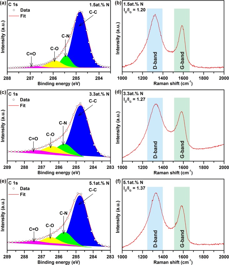
Doping of graphene with nitrogen was monitored by XPS and Raman spectroscopy. In survey XPS patterns recorded for N-doped graphene samples, peaks belonging to C, N, and O were clearly observed (see Figure S2 and Table S2 in Supporting Information). The content of nitrogen was found to increase progressively with the temperature at which the thermal reduction of graphite oxide in the presence of ammonia was conducted (i.e., 400 °C, 1.5 at. % of N; 600 °C, 3.3 at. % of N; 800 °C, 5.1 at. % of N). The presence of nitrogen was further evidenced in the high-resolution C 1s XPS profile, which showed the emergence of a peak at a binding energy of around 285.5 eV corresponding to the C–N bond (see Figure 1a,c,e).25 The C–N spectral component increased in area with the level of N-doping. A small shift in the maximum of the C–N peak witnessed for the three N-doped graphene samples can be explained in terms of impossibility to distinguish differently coordinated nitrogen atoms with carbon atoms in graphene with similar binding energy values in the C 1s domain and the significant overlap of the C–N and C–O spectral components. High-resolution N 1s XPS patterns of N-doped graphene samples (see Figure 2 and Figure S3 and Table S3 in Supporting Information) showed three distinct peaks corresponding to nitrogen in different configurations inside a graphene lattice or attached covalently to a graphene sheet (see Figure 3), i.e., pyridinic nitrogen (at ∼398.3 to ∼398.5 eV), graphitic nitrogen (at ∼401.0 to ∼401.5 eV), and chemisorbed N/N2 (at ∼404.5 to ∼405.5 eV). In contrast, no traces of pyrrolic nitrogen, usually present at ∼400.0 eV, were observed (compare the high-resolution N 1s XPS patterns shown in Figure 2 and Figure S3 in Supporting Information with Figure 3).36 The pyridinic and graphitic nitrogen were viewed as nitrogen incorporated inside the graphene lattice, whereas chemisorbed N/N2 was viewed as nitrogen adsorbed as adatoms. The presence of N/N2 was further confirmed by TGA and EGA techniques with gas electron ionization mass spectrometry, indicating emission of a fragment with m/z = 28 (for N/N2) above 300 °C (see Figure S4 in Supporting Information). In addition, as no fragments with m/z = 30 and 48 were detected, the samples were considered free of any NO and NO2 species, respectively. This agrees with the analysis of the Raman spectra of N-doped graphene samples as no Raman peaks around 1430 cm–1, characteristic for NO and NO2 species,36 are observed (see Figure 1b,d,f).
Figure 1.
High-resolution C 1s XPS patterns of the (a) GN0.015, (c) GN0.033, (e) and GN0.051 sample with bonds indicated. Raman spectra of the (b) GN0.015, (d) GN0.033, and (f) GN0.051 sample with the ID/IG ratio indicated.
Figure 2.
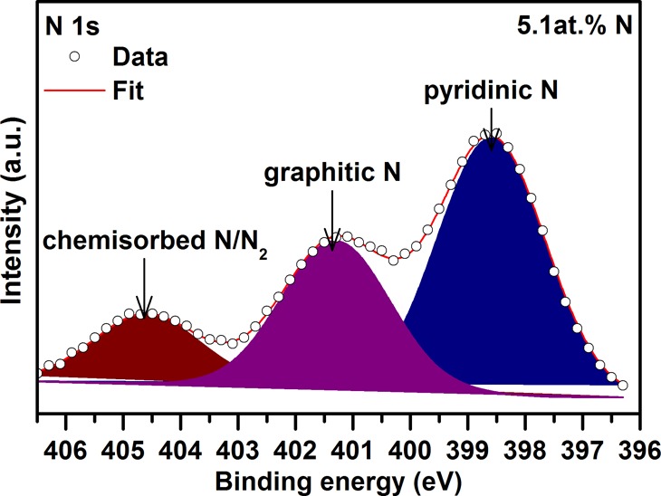
High-resolution N 1s XPS pattern of the GN0.051 sample with peaks assigned to differently coordinated nitrogen.
Figure 3.
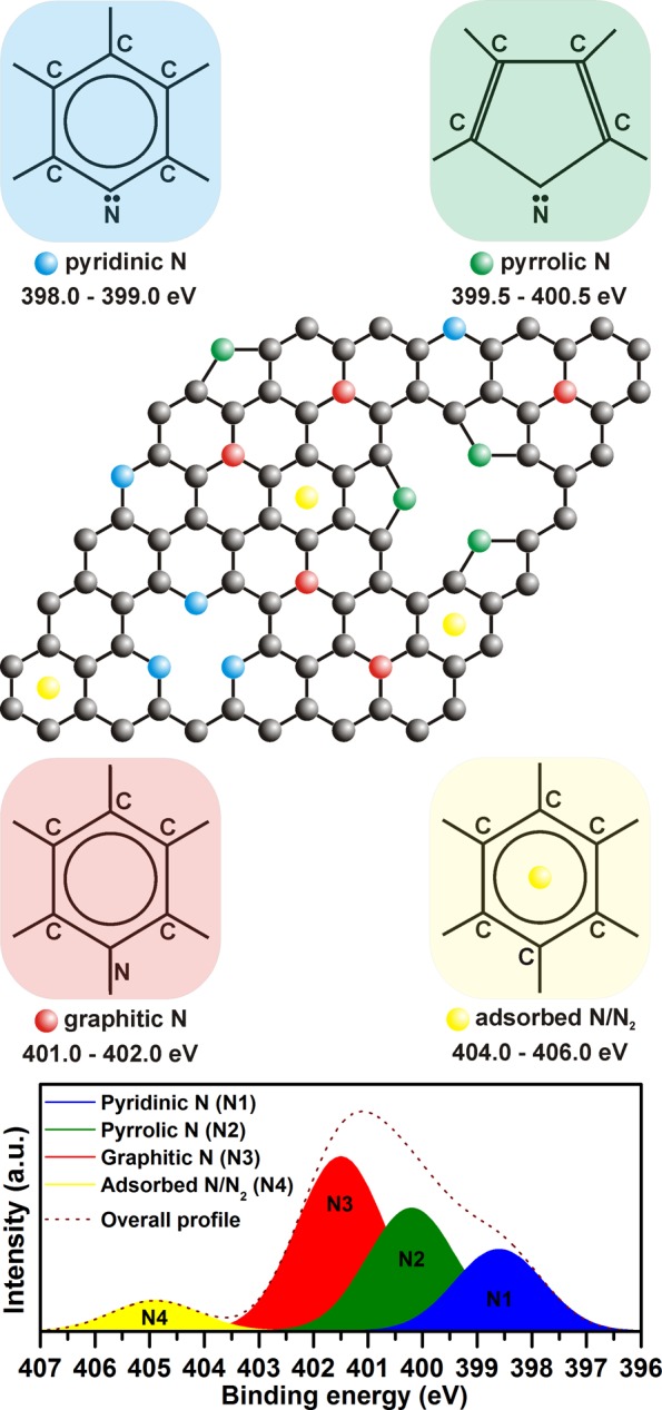
Scheme showing different bonding configurations of nitrogen in N-doped graphene and corresponding peaks in a simulated high-resolution N 1s XPS pattern.
Raman spectra of the GN0.015, GN0.033, GN0.051, and TRGO sample are shown in Figure 1b,d,f and Figure S1c in Supporting Information. It can be seen that on increasing the level of N-doping, the D-to-G band intensity ratio, ID/IG, increased. It is known that if nitrogen enters the graphene lattice, the intensity of the D-band, ID, in the Raman spectrum of graphene is enhanced due to defects that emerge upon incorporation of nitrogen into the graphene structure.25 This provides further evidence that under the synthetic conditions used, accommodation of nitrogen into the graphene lattice was strongly favored over a simple adsorption/addition process.
If defects are introduced into graphene, paramagnetic centers emerge that may interact via suitable mediators (i.e., π-conduction electrons, overlapping orbitals favoring superexchange mechanism, etc.) to generate long-range magnetic ordering in the 2D lattice. Under such conditions, the magnetic susceptibility of graphene, χ, involves three contributions, i.e., χ = χdia + χpara + χferro, where χdia is the diamagnetic term including orbital, Landau and core diamagnetic contributions, χpara is the paramagnetic term including noninteracting (isolated) defect-induced paramagnetic centers, Pauli paramagnetic contribution from conduction electron and van Vleck contribution, and χferro is the FM term describing the magnetic response of interacting defect-induced paramagnetic centers.37 As expected, pristine TRGO behaved in a diamagnetic manner with only a tiny paramagnetic response at low temperatures (see Figure S1d in Supporting Information) due to paramagnetic centers emerging as a result of defects and/or the negligible content of oxygen functionalities, which were most likely at the edges; the profile of χmass of TRGO well matched the modified Curie law, i.e., χmass = χmass,dia + C/T, where χmass,dia is the diamagnetic contribution, C is the Curie constant, and T is the temperature.
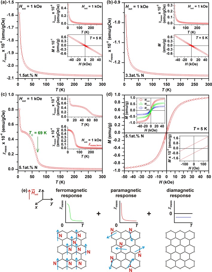
Similarly, the temperature evolution of χmass measured for the GN0.015 and GN0.033 sample also obeyed the modified Curie law (see Figure 4a,b). The number of paramagnetic centers increased upon increasing the level of N-doping, as expected and evidenced by an enhanced paramagnetic Curie contribution (see insets in Figure 4a,b). However, N-doping at such levels did not imprint any magnetic configuration (as confirmed by theoretical calculations discussed below) and the induced paramagnetic centers were far from each other, precluding the establishment of a long-range magnetic ordering. Thus, the GN0.015 and GN0.033 sample showed dominant diamagnetic behavior, as also witnessed from the isothermal magnetization curves measured at 5 K (see insets in Figure 4a,b).
Figure 4.
Temperature evolution of the mass magnetic susceptibility, χmass, of the (a) GN0.015 and (b) GN0.033 sample recorded under an external magnetic field of 1 kOe. The insets in panel (a) and (b) show the temperature profile of χmass after subtraction of the diamagnetic component and behavior of the 5 K hysteresis loop of the GN0.015 and GN0.033 sample, respectively. (c) Temperature evolution of χmass for the GN0.051 sample recorded under an external magnetic field of 1 kOe with the Curie temperature, TC, indicated. The insets show the trend of χmass at low temperatures and the temperature profile of the FM contribution, χmass,ferro, derived from fitting the measured χmass. (d) Hysteresis loop of the GN0.051 sample measured at a temperature of 5 K. The insets show the behavior of the hysteresis loop around the origin with the coercivity marked and field-dependent profiles of magnetization for the ferromagnetic, Mferro, and paramagnetic, Mpara, component derived from fitting the measured isothermal magnetization curve. (e) Scheme showing different magnetic fractions in the GN0.051 sample and their respective profiles of χmass.
Interestingly, for the GN0.051 sample, the temperature profile of χmass was drastically different compared to the GN0.015 and GN0.033 sample as it could not be described by the modified Curie law. On lowering the temperature, χmass showed a saturation tendency followed by an abrupt increase, indicating two contributions, i.e., FM and paramagnetic (see Figure 4c–e); contrary to the graphene systems with a lower N-doping, the diamagnetic term was found to be negligible here. The presence of both magnetic fractions can be explained by assuming that the N-doped graphene sheets within the sample contained nitrogen in different structural configurations, which have a different impact on the magnetism of graphene, as predicted by the theory discussed below. Moreover, it is known that even in sheets showing FM behavior, isolated paramagnetic centers may evolve owing to the presence of vacancies and defects of topological and edge nature.4−10 In order to fit the temperature evolution of χmass, the paramagnetic term was fitted using the Curie function (i.e., χmass = C/T) over the whole temperature interval, whereas a model function involving a combination of the Curie–Weiss law (i.e., χmass = C/(T – θ), where θ is the Weiss temperature) at high temperatures and Brillouin function within the mean-field approximation at low temperatures was constructed to describe the FM contribution (see inset in Figure 4c). The fitting yielded θ ≈ 69 K, angular momentum number J ≈ 1.19, and a weight-normalized ratio of ferromagnetic-to-paramagnetic contribution equal to 1.66. Note that the value of J is not an integral multiple of 0.5 as expected and must be treated as an average over all the N-doped graphene sheets in the GN0.051 sample as the sheets can have different C–N configurations/arrangements with different net magnetic moments (see below), as already reported for N-doped and S-doped graphene systems.22,24 Furthermore, θ can be assigned to the Curie temperature, TC, marking the transition from the paramagnetic to FM regime on lowering the temperature. Thus, in accordance with the theory, if the concentration of nitrogen exceeds a threshold value (>5 at. % of N), magnetically active motifs inside the graphene lattice evolve, eventually leading to a magnetically ordered (i.e., FM) state at low temperatures.
Transition of graphene with ∼5.1 at. % of N to the low-temperature FM regime was further confirmed by a series of hysteresis loops measured over the temperature range from 5 to 300 K (see Figure 4d and Figure S5 in Supporting Information). At 5 K, the isothermal magnetization curve showed hysteresis with a coercivity of ∼92 Oe (see inset in Figure 4d) and saturation magnetization reaching 1.09 emu/g. The derived value of the saturation magnetization is of identical order as reported for S-doped graphenes22 and vertical graphenes,38 which are regarded as the magnetically strongest carbon-based systems prepared to date. The nonzero value of the coercivity implies that N-doping imprints magnetic anisotropy on the graphene lattice, establishing an easy axis of magnetization along which the magnetic moments of the generated paramagnetic centers energetically prefer to lie. Following the mathematical procedures of Liu et al.24 and Tuček et al.22 and assuming the J value and weighted ferromagnetic-to-paramagnetic ratio derived from the χmass vs T profile, we next attempted to separate the paramagnetic and FM contribution in the 5 K isothermal magnetization curve (see inset in Figure 4d). The fitting yielded a saturation magnetization of ∼0.65 emu/g and ∼0.37 emu/g for the FM and paramagnetic contributions, respectively. On raising the temperature, the coercivity decreased to zero (see inset in Figure S5b in Supporting Information) and the hysteresis was lost at a temperature of ∼70 K (see Figure S5a in Supporting Information), indicating a transition from the FM to paramagnetic regime.
Thus, the experimental results suggested that when the concentration of nitrogen was increased and it became firmly embedded in the crystal lattice of graphene, the number of induced paramagnetic centers increased, eventually forming magnetically active motifs with conduction electrons providing interaction pathways between them and establishing long-range magnetic ordering upon decreasing the temperature. It was hypothesized that upon further increasing the nitrogen concentration in the graphene lattice, magnetic interactions would be strengthened, as reflected by a shift of TC to higher temperature. Moreover, the presence of more paramagnetic centers would enhance the saturation magnetization, approaching the values observed for S-doped and vertically oriented graphenes,22,38 i.e., systems where the magnetic features are imprinted by defects. Here, it should be stated that the observed ferromagnetism above 5 at. % of N was probably a consequence of the different nitrogen motifs identified in the samples by XPS (graphitic, pyridinic, and chemisorbed N/N2). Importantly, we did not identify pyrrolic nitrogen in the samples, which has previously been shown to cause a fall in magnetization values.10
To decipher the effect of nitrogen in various bonding configurations (as identified by XPS, Figure 2 and Figure S3 in Supporting Information) on the magnetic properties of graphene, we performed a first-principles27−30 study of the structural, electronic, and magnetic properties of N-doped graphenes. The “magnetic contributions” of individual N-motifs were also addressed in details. We used a rectangular graphene cell containing 96 atoms, which was computationally tractable and enabled the experimentally determined total and relative (among different bonding configurations) content of nitrogen to be followed closely. Specifically, we considered chemisorbed nitrogen (both N and N2) on the top of the graphene sheet and two graphitic and pyridinic nitrogen atoms in the graphene lattice (see Figure 5).
Figure 5.
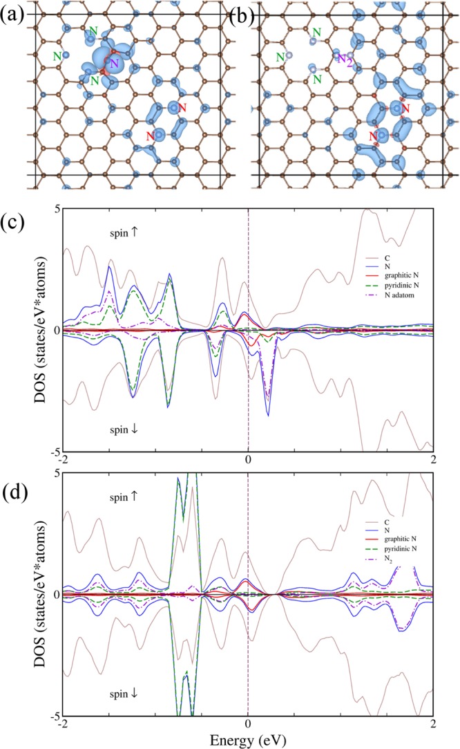
Top view of graphene doped with graphitic (in para configurations), trimerized pyridinic and chemisorbed (a) N and (b) N2 marked respectively by red, green, and magenta, with positive (negative) spin densities plotted in blue (red) for isosurfaces at ±1 × 10⁻³ (panel (a)) and ±2.5 × 10⁻⁴eÅ–3 (panel (b)). (c, d) The corresponding DOS plot for configuration shown in panel (a) and panel (b), respectively.
The computational data fully supported the experimental results. In particular, the energetically most stable structures, as presented in Figure 5a,b, exhibited FM ordering with 1.3 and 0.3 μB magnetic moment per supercell for N and N2, respectively, chemisorbed on the graphene surface. The density of state (DOS) plots presented in Figure 5c,d indicated exchange coupling mediated by the conduction electrons. Moreover, the strong spin-polarized electron features at the Fermi level in the DOS structures showed a predominant contribution from the graphitic N atoms, which highlights their important role in developing Stoner-like magnetism in N-doped graphenes.22,39 It should be noted that depending on the position of nitrogen on the graphene surface with respect to the graphitic and pyridinic nitrogen atoms, a large number of possible magnetic configurations were found with a varying effective magnetic moment per cell and exhibiting both FM and antiferromagnetic behavior or even disappearance of magnetic order. This may explain the complexity of the magnetic measurements discussed above for the GN0.051 sample, as the experimental response represented an average over a large number of structures with different net magnetic moments.
Thus, to understand the role and contribution of individual nitrogen motifs in triggering magnetism in N-doped graphenes, we carried out an extensive set of additional calculations with a smaller cell containing 48 atoms. The magnetic properties of graphene doped with graphitic nitrogen exhibited a strong dependence on both the nitrogen concentration and configurations. Nonmagnetic ground state structures doped by 2.1, 4.2, and 6.25 at. % of graphitic nitrogen (the percentages used result from the size of the cell employed in the calculations) are shown in Figure S6 in Supporting Information. The magnetism of graphene doped with graphitic nitrogen has been attributed to delocalized electrons occupying narrow peaks at the Fermi level (EF).22,39 Graphene doped with 2.1 at. % of nitrogen was predicted to be nonmagnetic, in accord with DFT calculations by Wang et al.,9 and the narrow electron donor states near EF were absent in the partial density of states (PDOS). At 4.2 at. % of nitrogen, the computational screening identified a magnetic structure with a magnetic moment of ∼0.2 μB per supercell in which N atoms substituted C atoms at para positions (see Figure 6). The same motif was responsible for triggering ferromagnetism in the larger 96-atom cell, which highlights the importance of the graphitic nitrogen motif in imprinting FM order in N-doped graphene. N-doping generating the FM state gave rise to a strong pz electron peak at the Fermi level in the electronic structure according to PDOS, similar to recent reports for graphene doped with 4.2 at. % of sulfur.22 The magnetic polarization was confined to a narrow part of the cell, in zigzag directions between the doping atoms, as can be seen in the inset in Figure 6 presenting isosurfaces of spin densities. Importantly, formation of zigzag edges by cutting graphene along a certain crystallographic direction has been shown to give rise to peculiar edge localized states near the Fermi level responsible for the spontaneous formation of magnetic ordering in graphene nanoribbons.40
Figure 6.
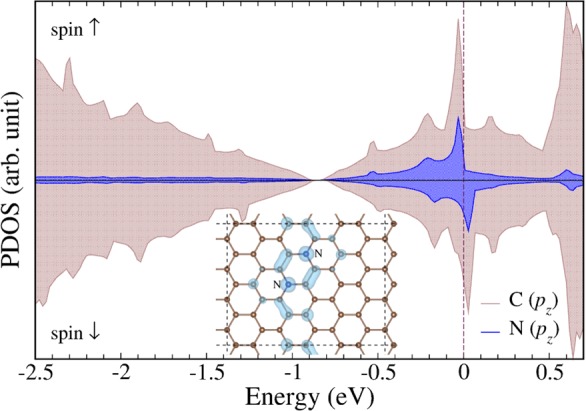
Partial densities of states calculated for graphene doped with nitrogen embedded in the lattice at para positions at a concentration of 4.2 at. %. The supercell is shown in the inset, where an isosurface of spin-density plotted at ±5 × 10⁻⁴eÅ–3 is also displayed.
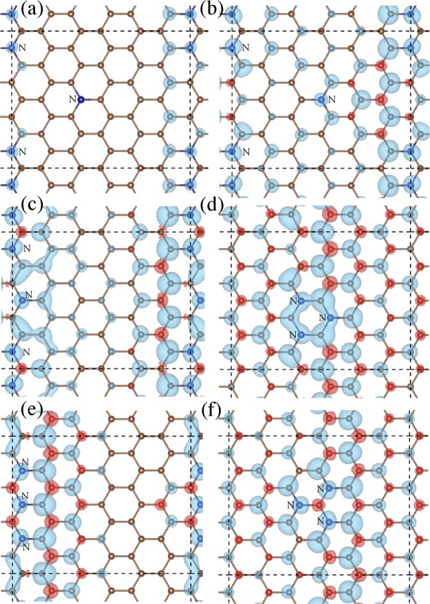
The DFT calculations also suggested that at 6.25 at. % of graphitic nitrogen, a greater number of magnetic configurations with the magnetic moment varying between 0.1 and 0.8 μB/supercell (see Figure 7 and Figure S7 in Supporting Information) were produced. These magnetic structures contained two N atoms in the meta configuration embedded in the graphene lattice. The magnetic behavior of this system could be tuned by changing the position of the third N atom in the host lattice as it stayed on the zigzag paths between the other two N atoms. Finally, because of the similar atomic sizes of nitrogen and carbon atoms, incorporation of nitrogen into the honeycomb network of graphene did not lead to any significant distortion of the host lattice. In-plane atomic displacements caused by nitrogen were below 2% of the C–C distance of pristine graphene and the system remained planar. Strain-induced magnetism in N-doped graphene was thus excluded.
Figure 7.
Top view of graphene doped with nitrogen at a concentration of 6.25 at. %. Positive (negative) spin densities are plotted in blue (red) for isosurfaces at ±5 × 10⁻⁴eÅ–3: (a) 0.1, (b) 0.4, (c) 0.7, (d) 0.8, (e) 0.4, and (f) 0.6 μB per supercell.
We also considered the effect of nitrogen atoms substituting carbons in the graphene lattice (employing a 48-atom graphene cell) on pyrrolic bonding sites. A single pyrrolic nitrogen in graphene occupied a site inside the pentagonal ring in the vicinity of single vacancy (SV) or divacancy (DV) defect (see Figure S8a,b in Supporting Information). Substitution by monomeric pyrrolic nitrogen did not result in any long-range magnetic order. Importantly, replacing one of the C atoms participating in the reconstructed C–C bond with an N atom led to opening of the 5-membered ring and S = 1/2 paramagnetism41 due to the carbon dangling bond. Such a bonding configuration transformed the initial pyrrolic nitrogen into pyridinic nitrogen (see Figure S8c,d in Supporting Information). We also considered the effect of adding pyrrolic nitrogen inside the octagonal ring of the DV defect (Figure S8e,f in Supporting Information), as proposed in the work of Li et al.23 The present calculations indicated that the nitrogen atom moved to the neighboring 5-membered ring, in accord with the study by Lin et al.,42 forming a 6-membered ring upon relaxation in which nitrogen (transformed into pyridinic) was nonmagnetic.
Next, we considered the role of pyridinic nitrogen, which was also identified as an important motif in the experimental samples. Besides monomeric pyridinic nitrogen (S = 0 or S = 1/2 due to carbon dangling bonds), we also considered dimerized (with S = 1/2 magnetic moment due to carbon dangling bond) and trimerized pyridinic nitrogen (with a magnetic moment of 0.3 μB per supercell). Note that the calculated ground state arrangements of multiple pyridinic nitrogen in the graphene lattice were in agreement with annular dark-field imaging reported in the work by Lin et al.42 However, according to DOS of the trimerized pyridinic nitrogen (see Figure S9 in Supporting Information), the electronic structure indicated that indirect exchange mediated by the conduction electrons was strongly compromised compared to the exchange coupling developed for graphene doped with graphitic nitrogen (compare Figure 6 and Figure S9 in Supporting Information). This is in line with the suppressed magnetic moment of trimerized pyridinic nitrogen in comparison to that of trimerized graphitic nitrogen (see the structure presented in Figure 7f and DOS plot in Figure S7f in Supporting Information). It is also important to mention that half-metallic properties were recently predicted for the graphene-based C4N3 polymer,43 i.e., a 2D radical polymer containing many trimerized pyridinic nitrogens. In contrast, the DOS plot presented in Figure S9 in Supporting Information showed finite (nonzero) density of states above EF in both spin-up and spin-down channel, which is most likely due to a significantly lower concentration of trimerized pyridinic nitrogen in the present study.
Finally, we investigated whether magnetism in graphene can also be induced by nitrogen adatoms/molecule, which were identified in the XPS patterns and TGA/EGA measurements. Thus, structures resulting from both nitrogen additions on a pristine graphene layer and simultaneous single nitrogen atom addition and graphitic substitution were analyzed (see Figure S10 and Figure S11 in Supporting Information).
A single N-adatom carried a magnetic moment of 0.5 μB, which can be understood based on an electron counting argument: two valence electrons formed covalent bonds with neighboring C atoms, two formed a lone-pair, and the fifth valence electron gave rise to the magnetic moment. However, the substrate atoms remained nonmagnetic. Adding another nitrogen atom contributed 0.5 μB, but no magnetic moments were induced on the C atoms. By placing another nitrogen atom in a close proximity to the preadsorbed adatom, an N2 dimer spontaneously formed, which was adsorbed over the surface and had zero magnetic moment. Adatom addition on graphene containing 2.1 at. % of graphitic nitrogen (see Figure S11 in Supporting Information) also did not induce a magnetic response in the system.
To conclude, the computational study allowed elucidation of the synergistic effect of nitrogen atoms in various bonding configurations, as evidenced from high-resolution XPS data. To follow closely the total and relative content of nitrogen in the experimentally prepared samples, we considered graphitic nitrogen in the para configuration, which turned out to promote formation of the motif most important for imprinting magnetism in graphene, followed by trimerized pyridinic nitrogen and chemisorbed N adatoms. In the ground state, the structure resulting from the combined effects of all these species is strongly FM. However, it should be noted that coupling between pyridinic nitrogens is much less effective in maintaining the FM structure, and chemisorbed nitrogen adatoms can only generate paramagnetism. Further, chemisorbed N2 only results in a nonmagnetic states. Finally, pyrrolic nitrogen has no effect on magnetism in graphene, in line with the work by Ito et al.,10 who reported a decrease in the magnetization values with increasing concentration of pyrrolic nitrogen in the graphene lattice.
Conclusions
In summary, on the basis of electronic-structure calculations and magnetization measurements, we have provided new insights into the role of nitrogen as a highly electronegative n-type dopant for imprinting the magnetic properties to graphene. The magnetic features of N-doped graphene depend on both the nitrogen concentration and the configuration in the host lattice, with a complex interplay between graphitic, pyridinic, and chemisorbed nitrogen. Among these structural motifs, graphitic nitrogen plays the principal magnetic role, as corroborated by DFT calculations. Importantly, below 5 at. % of nitrogen, graphene behaves dominantly as a diamagnet; paramagnetic centers are induced upon doping; however, they do not produce magnetically active motifs. If the doping concentration is increased above the threshold doping value, magnetic interactions mediated by the conduction electron system emerge between the substitution-generated paramagnetic centers. Experimentally, graphene doped with nitrogen at a concentration level of 5.1 at. % shows a transition to an FM state at the Curie temperature of ∼69 K and saturation magnetization reaching 1.09 emu/g. Such a high value of the saturation magnetization ranks N-doped graphenes among the magnetically strongest graphene-based systems developed so far for which the magnetic properties are imprinted by defects. As N-doping is also expected to maintain or even improve the electric (i.e., conduction) features of graphene, the present work opens possibilities for further optimization of N-doped graphenes (e.g., exclusive presence of graphitic nitrogen) to produce new kinds of spintronic materials.
Acknowledgments
The authors acknowledge the support from the Ministry of Education, Youth and Sports of the Czech Republic under Project No. LO1305 and assistance provided by the Research Infrastructure NanoEnviCz supported by the Ministry of Education, Youth and Sports of the Czech Republic under Project No. LM2015073. P. B. acknowledges Palacký University institutional support. The authors thank Mrs. Ariana Fargašová and Dr. Juri Ugolotti (both from the Regional Centre of Advanced Technologies and Materials, Faculty of Science, Palacky University in Olomouc, Czech Republic) for Raman spectroscopy and TGA/EGA measurements, respectively. Z. S. and V. M. were supported by the Czech Science Foundation (GACR No. 15-09001S) and by specific university research (MSMT No. 20-SVV/2016). M. O. acknowledges funding from an ERC Consolidator grant (H2020) No. 683024. M.P. acknowledges a Tier 2 grant (MOE2013-T2-1-056; ARC 35/13) from the Ministry of Education, Singapore.
Supporting Information Available
The Supporting Information is available free of charge on the ACS Publications website at DOI: 10.1021/jacs.6b12934.
Figures S1–S11; Tables S1–S4 (PDF)
Author Contributions
# P. B. and J. T. contributed equally to this work.
The authors declare no competing financial interest.
Supplementary Material
References
- Novoselov K. S.; Geim A. K.; Morosov S. V.; Jiang D.; Zhang Y.; Dubonos S. V.; Grigorieva I. V.; Firsov A. A. Science 2004, 306 (5696), 666–669. 10.1126/science.1102896. [DOI] [PubMed] [Google Scholar]
- Geim A. K.; Novoselov K. S. Nat. Mater. 2007, 6 (3), 183–191. 10.1038/nmat1849. [DOI] [PubMed] [Google Scholar]
- Tombros N.; Jozsa C.; Popinciuc M.; Jonkman H. T.; van Wees B. J. Nature 2007, 448 (7153), 571–574. 10.1038/nature06037. [DOI] [PubMed] [Google Scholar]
- Yazyev O. V.; Helm L. Phys. Rev. B: Condens. Matter Mater. Phys. 2007, 75 (12), 125408. 10.1103/PhysRevB.75.125408. [DOI] [Google Scholar]
- Yazyev O. V.; Katsnelson M. I. Phys. Rev. Lett. 2008, 100 (4), 047209. 10.1103/PhysRevLett.100.047209. [DOI] [PubMed] [Google Scholar]
- Palacios J. J.; Fernández-Rossier J. Phys. Rev. B: Condens. Matter Mater. Phys. 2008, 77 (19), 195428. 10.1103/PhysRevB.77.195428. [DOI] [Google Scholar]
- Červenka J.; Katsnelson M. I.; Flipse C. F. J. Nat. Phys. 2009, 5 (11), 840–844. 10.1038/nphys1399. [DOI] [Google Scholar]
- Soriano D.; Leconte N.; Ordejón P.; Charlier J.-C.; Palcios J.-J.; Roche S. Phys. Rev. Lett. 2011, 107 (1), 016602. 10.1103/PhysRevLett.107.016602. [DOI] [PubMed] [Google Scholar]
- Wang Z.; Qin S.; Wang C. Eur. Phys. J. B 2014, 87 (4), 88. 10.1140/epjb/e2014-40719-y. [DOI] [Google Scholar]
- Ito Y.; Christodoulou C.; Nardi M. V.; Koch N.; Kläui M.; Sachdev H.; Müllen K. J. Am. Chem. Soc. 2015, 137 (24), 7678–7685. 10.1021/ja512897m. [DOI] [PubMed] [Google Scholar]
- Poh H. L.; Pumera M. ChemElectroChem 2015, 2 (2), 190–199. 10.1002/celc.201402307. [DOI] [Google Scholar]
- Qu L.; Liu Y.; Baek J.-B.; Dai L. ACS Nano 2010, 4 (3), 1321–1326. 10.1021/nn901850u. [DOI] [PubMed] [Google Scholar]
- Wang X.; Li X.; Zhang L.; Yoon Y.; Weber P. K.; Wang H.; Guo J.; Dai H. Science 2009, 324 (5928), 768–771. 10.1126/science.1170335. [DOI] [PubMed] [Google Scholar]
- Wang Z. G.; Li P. J.; Chen Y. F.; Liu J. B.; Zhang W. L.; Guo Z.; Dong M. D.; Li Y. R. J. Mater. Chem. C 2015, 3 (24), 6301–6306. 10.1039/C5TC00563A. [DOI] [Google Scholar]
- Reddy A. L. M.; Srivastava A.; Gowda S. R.; Gullapalli H.; Dubey M.; Ajayan P. M. ACS Nano 2010, 4 (11), 6337–6342. 10.1021/nn101926g. [DOI] [PubMed] [Google Scholar]
- Kwon O. S.; Park S. J.; Hong J. Y.; Han A. R.; Lee J. S.; Lee J. S.; Oh J. H.; Jang J. ACS Nano 2012, 6 (6), 1486–1493. 10.1021/nn204395n. [DOI] [PubMed] [Google Scholar]
- Jeong H. M.; Lee J. W.; Shin W. H.; Choi Y. J.; Shin H. J.; Kang J. K.; Choi J. W. Nano Lett. 2011, 11 (6), 2472–2477. 10.1021/nl2009058. [DOI] [PubMed] [Google Scholar]
- Chen L. F.; Zhang X. D.; Liang H. W.; Kong M. G.; Guan Q. F.; Chen P.; Wu Z. Y.; Yu S. H. ACS Nano 2012, 6 (8), 7092–7102. 10.1021/nn302147s. [DOI] [PubMed] [Google Scholar]
- Huang X.; Qi X. Y.; Boey F.; Zhang H. Chem. Soc. Rev. 2012, 41 (2), 666–686. 10.1039/C1CS15078B. [DOI] [PubMed] [Google Scholar]
- Wang Y.; Shao Y. Y.; Matson D. W.; Li J. H.; Lin Y. H. ACS Nano 2010, 4 (4), 1790–1798. 10.1021/nn100315s. [DOI] [PubMed] [Google Scholar]
- Chaban V. V.; Prezhdo O. V. J. Am. Chem. Soc. 2015, 137 (36), 11688–11694. 10.1021/jacs.5b05890. [DOI] [PubMed] [Google Scholar]
- Tuček J.; Błoński P.; Sofer Z.; Šimek P.; Petr M.; Pumera M.; Otyepka M.; Zbořil R. Adv. Mater. 2016, 28 (25), 5045–5053. 10.1002/adma.201600939. [DOI] [PubMed] [Google Scholar]
- Li J. Y.; Li X. H.; Zhao P. H.; Lei D. Y.; Li W. L.; Bai J. T.; Ren Z. Y.; Xu X. L. Carbon 2015, 84, 460–468. 10.1016/j.carbon.2014.12.024. [DOI] [Google Scholar]
- Liu Y.; Tang N. J.; Wan X. G.; Feng Q.; Li M.; Xu Q. H.; Liu F. C.; Du Y. W. Sci. Rep. 2013, 3, 2566. 10.1038/srep02566. [DOI] [PMC free article] [PubMed] [Google Scholar]
- Wang H.; Maiyalagan T.; Wang X. ACS Catal. 2012, 2 (5), 781–794. 10.1021/cs200652y. [DOI] [Google Scholar]
- Lazar P.; Zbořil R.; Pumera M.; Otyepka M. Phys. Chem. Chem. Phys. 2014, 16 (27), 14231–14235. 10.1039/c4cp01638f. [DOI] [PubMed] [Google Scholar]
- Kresse G.; Furthmüller J. Phys. Rev. B: Condens. Matter Mater. Phys. 1996, 54 (16), 11169–11186. 10.1103/PhysRevB.54.11169. [DOI] [PubMed] [Google Scholar]
- Kresse G.; Joubert D. Phys. Rev. B: Condens. Matter Mater. Phys. 1999, 59 (3), 1758–1775. 10.1103/PhysRevB.59.1758. [DOI] [Google Scholar]
- Blöchl P. E. Phys. Rev. B: Condens. Matter Mater. Phys. 1994, 50 (24), 17953–17979. 10.1103/PhysRevB.50.17953. [DOI] [PubMed] [Google Scholar]
- Perdew J. P.; Burke K.; Ernzerhof M. Phys. Rev. Lett. 1996, 77 (18), 3865–3868. 10.1103/PhysRevLett.77.3865. [DOI] [PubMed] [Google Scholar]
- Blöchl P. E.; Jepsen O.; Andersen O. K. Phys. Rev. B: Condens. Matter Mater. Phys. 1994, 49 (23), 16223–16233. 10.1103/PhysRevB.49.16223. [DOI] [PubMed] [Google Scholar]
- Bader R.Atoms in Molecules: A Quantum Theory; Oxford University Press: New York, 1990. [Google Scholar]
- Henkelman G.; Arnaldsson A.; Jonsson H. Comput. Mater. Sci. 2006, 36 (3), 354–360. 10.1016/j.commatsci.2005.04.010. [DOI] [Google Scholar]
- Sanville E.; Kenny S. D.; Smith R.; Henkelman G. J. Comput. Chem. 2007, 28 (5), 899–908. 10.1002/jcc.20575. [DOI] [PubMed] [Google Scholar]
- Nair R. R.; Tsai I.-L.; Sepioni M.; Lehtinen O.; Keinonen J.; Krasheninnikov A. V.; Castro Neto A. H.; Katsnelson M. I.; Geim A. K.; Grigorieva I. V. Nat. Commun. 2013, 4, 2010. 10.1038/ncomms3010. [DOI] [PubMed] [Google Scholar]
- Zhao L. B.; Huang Y. F.; Liu X. M.; Anema J. R.; Wu D. Y.; Ren B.; Tian Z. Q. Phys. Chem. Chem. Phys. 2012, 14, 12919. 10.1039/c2cp41502j. [DOI] [PubMed] [Google Scholar]
- Makarova T. L.; Shelankov A. L.; Zyrianova A. A.; Veinger A. I.; Tisnek T. V.; Lahderanta E.; Shames A. I.; Okotrub A. V.; Bulusheva L. G.; Chekhova G. N.; Pinakov D. V.; Asanov I. P.; Sljivancanin Z. Sci. Rep. 2015, 5, 13382. 10.1038/srep13382. [DOI] [PMC free article] [PubMed] [Google Scholar]
- Seo D. H.; Yue Z. J.; Wang X. L.; Levchenko I.; Kumar S. L.; Douc S. X.; Ostrikov K. Chem. Commun. 2013, 49 (99), 11633–11637. 10.1039/c3cc46218h. [DOI] [PubMed] [Google Scholar]
- Edwards D. M.; Katsnelson M. I. J. Phys.: Condens. Matter 2006, 18 (31), 7209–7225. 10.1088/0953-8984/18/31/016. [DOI] [Google Scholar]
- Fujita M.; Wakabayashi K.; Nakada K.; Kusakabe K. J. Phys. Soc. Jpn. 1996, 65 (7), 1920–1923. 10.1143/JPSJ.65.1920. [DOI] [Google Scholar]
- Nair R. R.; Sepioni M.; Tsai I.-L.; Lehtinen O.; Keinonen J.; Krasheninnikov A. V.; Thomson T.; Geim A. K.; Grigorieva I. V. Nat. Phys. 2012, 8 (3), 199–202. 10.1038/nphys2183. [DOI] [Google Scholar]
- Lin Y. C.; Teng P. Y.; Yeh C. H.; Koshino M.; Po-Chiu P. W.; Suenaga K. Nano Lett. 2015, 15 (11), 7408–7413. 10.1021/acs.nanolett.5b02831. [DOI] [PubMed] [Google Scholar]
- Lee E. C.; Choi Y. C.; Kim W. Y.; Singh N. J.; Lee S.; Shim J. H.; Kim K. S. Chem. - Eur. J. 2010, 16 (40), 12141–12146. 10.1002/chem.201000858. [DOI] [PubMed] [Google Scholar]
Associated Data
This section collects any data citations, data availability statements, or supplementary materials included in this article.


