Significance
Direct foam writing enables the construction of architected cellular ceramics with tailored microstructure, geometry, and mechanical properties. These bioinspired, hierarchical structures exhibit different modes of deformation as well as exceptional specific stiffness. This work represents an important step toward the scalable fabrication of architected porous materials, which may find potential application as lightweight structures, thermal insulation, tissue scaffolds, catalyst supports, and electrodes.
Keywords: porous, ceramics, foams, 3D printing, cellular architectures
Abstract
Hierarchical cellular structures are ubiquitous in nature because of their low-density, high-specific properties, and multifunctionality. Inspired by these systems, we created lightweight ceramic architectures composed of closed-cell porous struts patterned in the form of hexagonal and triangular honeycombs by direct foam writing. The foam ink contains bubbles stabilized by attractive colloidal particles suspended in an aqueous solution. The printed and sintered ceramic foam honeycombs possess low relative density (∼6%). By tailoring their microstructure and geometry, we created honeycombs with different modes of deformation, exceptional specific stiffness, and stiffness values that span over an order of magnitude. This capability represents an important step toward the scalable fabrication of hierarchical porous materials for applications, including lightweight structures, thermal insulation, tissue scaffolds, catalyst supports, and electrodes.
Hierarchical cellular structures are ubiquitous in nature because of their mechanical efficiency and multifunctionality (1–4). Stochastic (foams) and periodic (2D honeycombs or 3D lattices) cellular architectures exhibit either bending- or stretching-dominated mechanical responses depending on their nodal connectivity (5). If structural motifs with different length scales are combined in a hierarchical manner within the same cellular structure, mixed mode mechanical responses are possible (5), including stretching–stretching [e.g., wood along the grain (6)], bending–bending [e.g., cork across the grain (7)], and bending–stretching [e.g., bird wings (5), bones (4), and wood across the grain (6)]. Additional functionality is also enabled by natural cellular architectures, including buckling resistance [e.g., stems and quills (8)], thermal management [e.g., cork (7)], structural color [e.g., feathers (9, 10)], and fluid transport [e.g., bones and plants (10)].
Inspired by these natural systems, bulk and additive manufacturing methods have been developed to create synthetic analogs. For example, monolithic objects composed of open or closed-cell foams can be cast from particulate suspensions that contain pore-forming agents (i.e., porogens) (11) or particle-stabilized foams (PSFs) (12, 13). Although porous microstructures can be readily generated from myriad materials by those methods, they are limited to relatively simple structures that possess bending-dominated mechanical responses (13–15). Recently, multiscale metamaterials with properties heretofore unseen in engineered materials have been created by light-based 3D printing of photopolymerizable organic (16–21) and preceramic resins (22). Specifically, microlattices, octet structures, and tetrakaidecahedra with struts composed of hollow shells (16–18, 20), solid features (21, 22), or even finer trusses (16, 19) have been produced, which may exhibit bending, stretching, or mixed mode mechanical responses. However, these lattices are limited to open architectures constructed using photopolymerizable materials that must be subsequently transformed to ceramic or metal through some combination of coating and pyrolysis. Recent advances in directly printing ceramic (23) and metal (24) lattices open new avenues for lightweight structural components (2), thermal insulation (25), tissue scaffolds (26), catalyst supports (27), and electrodes (28).
Here, we report the fabrication and characterization of architected cellular ceramics with tunable microstructure, geometry, and stiffness via direct foam writing. Specifically, we print filamentary struts containing a closed-cell foam microstructure periodically arrayed in the form of hexagonal or triangular honeycombs (Fig. 1). Our PSF ink contains significant porosity that arises from entrained bubbles surrounded by colloidal particles in an aqueous suspension. By carefully controlling ink composition, print path, drying, and sintering conditions, we can programmably create architected cellular ceramics composed of bending-, stretching-, bending–bending-, or stretching–bending-dominated unit cells with density and stiffness that can be tailored over at least one order of magnitude. Importantly, these hybrid (open–closed cell) architectures exhibit exceptional specific stiffness compared with structures produced by either bulk foam casting or light-based 3D printing.
Fig. 1.
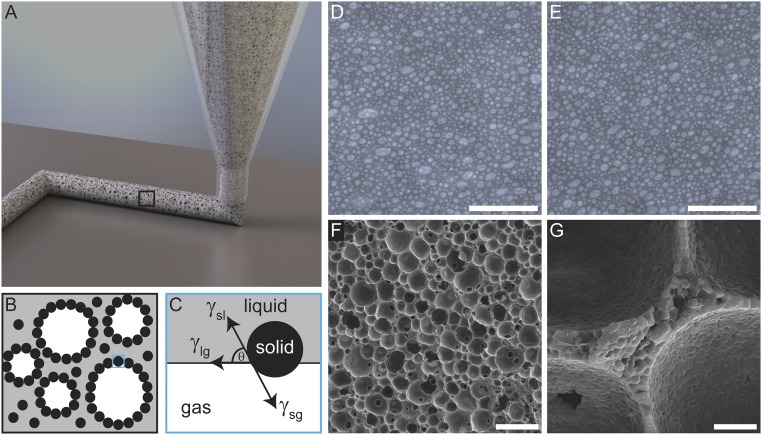
Direct foam writing. (A) Schematic view of direct foam writing of porous filamentary features. (B) Cross-sectional view of the PSF ink microstructure, in which entrained bubbles are surrounded by colloidal particles. (C) Bubble stabilization is enabled by controlling the contact angle of the colloidal particles such that they spontaneously adsorb onto the gas–liquid interface. Image of the wet foam microstructure (D) immediately after formulation and (E) after 1 wk of aging. (Scale bars: 500 μm.) (F) SEM micrographs of the sintered foam show a closed, highly macroporous morphology with cell wall thicknesses as thin as one grain (G). (Scale bars: F, 100 μm; G, 5 μm.)
Central to the fabrication of porous ceramic architectures is the design of a viscoelastic foam ink that embodies the requisite microstructural and rheological characteristics for direct foam writing. From a microstructural perspective, the wet ink must remain structurally stable over long time periods (>1 wk), possess modest bubble size (∼10–50 μm in diameter), and maintain high air content (>80%) after sintering. Reliably printing highly porous wet foams is inherently difficult because of the excess surface energy associated with the gas–liquid interface. If the gas–liquid interface is not well stabilized, bubble collapse will occur because of van der Waals attraction between adjacent interfaces, Ostwald ripening, or gravitational syneresis (29–34). Our foam ink is produced by mechanically frothing an aqueous suspension of partially hydrophobized alumina particles (34) (Movie S1). When the interfacial tension of the solid–liquid (γsl), liquid–gas (γlg), and solid–gas (γsg) interfaces is balanced, such that the contact angle (θ) of the particles and the solvent is between the range of 14° and 90° (calculated for 300-nm particles), the particles irreversibly and spontaneously adsorb onto liquid–gas (bubble) interfaces introduced during foaming (Fig. 1 B and C) (29–34). The adsorbed particles physically prevent van der Waals collapse and Ostwald ripening, and for sufficiently attractive interparticle interactions, arrest drainage, yielding a stable foam microstructure that retains its characteristic bubble content and size over long times (35). Direct imaging of wet foams stabilized by alumina particles (300 nm in diameter with a measured contact angle of 59° ± 5°) immediately after production (0 d) and aging (7 d) reveals total entrained porosities of 54.3 ± 2% and 54.8 ± 1%, respectively, with bubble sizes of 24.0 ± 1.4 and 22.9 ± 1.3 μm, respectively (Fig. 1 D and E). After drying and sintering, the total porosity within the ceramic foam microstructure increases to 85 ± 3% because of densification of the cell walls, whereas the characteristic pore size remains essentially unchanged (23.7 ± 1.4 μm) from the wet foam state (Fig. 1F). Notably, the cell walls, which are submicrometer in thickness, can be as thin as a single grain (Fig. 1G).
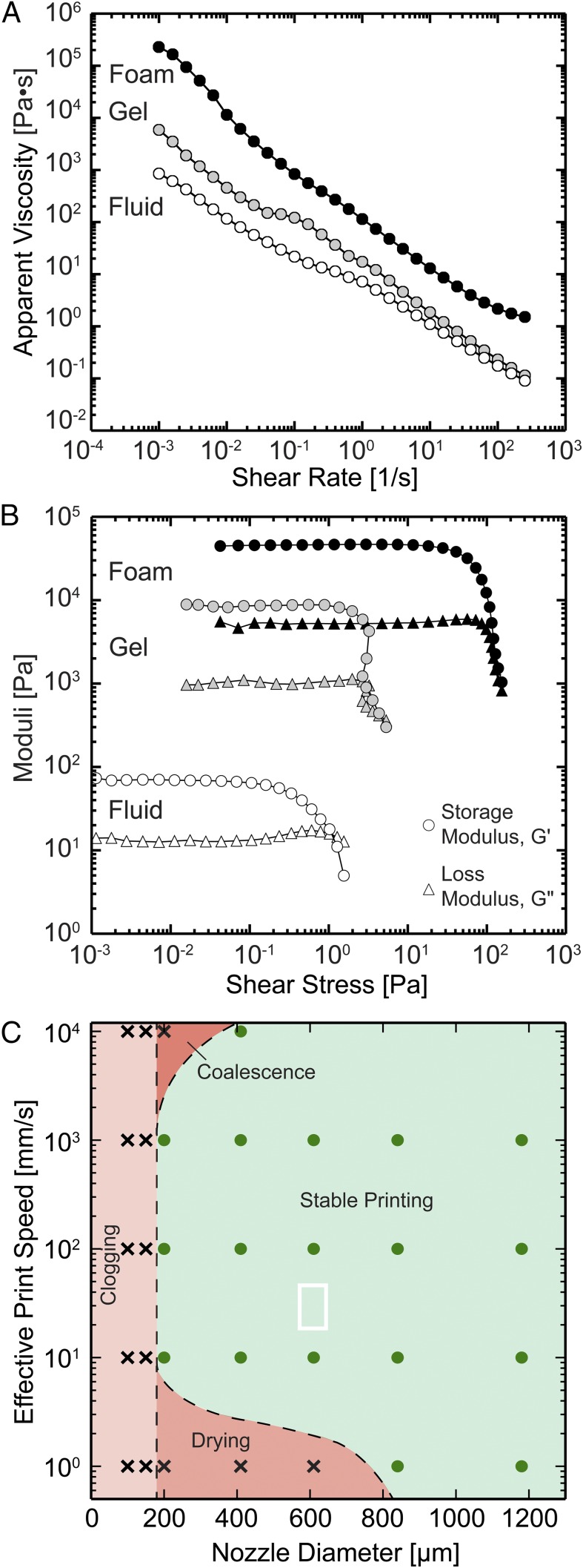
To facilitate printing, wet foam inks must exhibit significant shear thinning to allow extrusion through fine nozzles as well as sufficiently large storage modulus, G′, and shear yield strength, τy, to retain their filamentary shape on exiting the nozzle. The rheological properties of the ink at different stages of the formulation process are shown in Fig. 2. A charge stabilized, aqueous dispersion of alumina particles (35 vol % solids) that are partially hydrophobized using the surfactant, butyric acid, is prepared at pH < 3. The colloidal fluid is strongly shear thinning as evidenced by a pronounced decrease in its apparent viscosity from 900 to 0.1 Pa·s as the shear rate increases from 10−3 to 102 s−1. This flow behavior ensures that the colloidal fluid can be easily foamed at shear rates above 101 s−1 (i.e., its low viscosity does not impede aeration). However, because its plateau G′ (∼102 Pa) and τy (∼1 Pa) are low, gravitational syneresis occurs after foaming (Fig. S1). To impart structural stability, a weakly attractive interaction is induced between colloidal particles by increasing the solution pH ∼ 5, thereby reducing the particle charge. The resulting colloidal gel possesses an apparent viscosity that is equivalent to the colloidal fluid at shear rates above 10−1 s−1, facilitating aeration. Moreover, its plateau G′ (∼104 Pa) and τy (∼3 Pa) are now sufficiently high to prevent syneresis (Fig. 1 D and E). On foaming, the apparent viscosity of the final ink increases by an order of magnitude over all shear rates investigated, and concomitant increases in the plateau G′ (∼5·104 Pa) and τy (∼102 Pa) are observed. Importantly, our foam inks readily flow through nozzles (diameter ≥ 200 μm) at volumetric flow rates equivalent to effective print speeds from 10 mm/s to 10 m/s as shown in Fig. 2C. Particle clusters within the weakly attractive colloidal gel undergo clogging within finer nozzles (<200 μm in diameter), leading to the cessation of ink flow (36). For nozzle sizes that exceed ∼400 μm, the wet foam microstructure is preserved (i.e., bubbles do not coalesce) at effective print speeds as high as 10 m/s (Fig. S2). However, ink drying at the nozzle tip (<800 μm in diameter) occurs for the lowest printing speed (1 mm/s) investigated. Given our prior observations of direct writing of concentrated colloidal gels, we believe that a slip layer exists at the nozzle wall–foam ink interface that facilitates plug flow through the nozzle, thereby preserving the wet foam microstructure (23).
Fig. 2.
Ink rheology and printability. (A) Plot of apparent viscosity as a function of shear rate and (B) storage and loss moduli as a function of shear stress for various processing steps in the foam ink formulation process. (C) Processing map for direct foam printing, which denotes regions of stable (green) and unstable (red) printing, with the white box highlighting parameters used to print hexagonal and triangular foam-based honeycombs. [Note that unstable printing arises because of one of three failure mechanisms: (i) foam ink clogging in fine nozzles (light red), (ii) foam ink drying at the nozzle tip at low printing speeds (red), or (iii) bubble coalescence at high printing speeds and fine nozzle sizes (dark red)].
Fig. S1.
Foam processing. (A) Optical image of the foam precursor solution (colloidal fluid, pH < 3) after foaming. Air is introduced during foaming, but gravitational syneresis immediately destabilizes the foam. (B) Image of the colloidal gel (pH 6) before foaming and (C) foam microstructure obtained after foaming. Note that the bubble content and characteristic size depend strongly on pH, where 54.3 ± 2% porosity and 24.0 ± 1.4-μm pores are entrained at pH 5 compared with 29.2 ± 2% porosity and 10.8 ± 1.0-μm pores at pH 6. (Scale bar: 500 μm.) (D) SEM image of the sintered ceramic foam microstructure (shown in Fig. 2) after printing through a 610-μm nozzle at a flow rate of 1 mL/min. (Scale bar: 100 μm.)
Fig. S2.
Printing parameter effects on wet foam microstructure. (A) The initial foam microstructure before printing. The foam microstructures after printing at (B) 40 mm/s through a 610-μm-diameter nozzle, which are similar to the printing parameters used for creating the foam-based hexagonal and triangular honeycombs, (C) 103 mm/s through a 200-μm-diameter nozzle, and (D) 104 mm/s through a 410-μm-diameter nozzle. In all cases, the overall porosity and characteristic pore size of the printed foams (B–D) are nearly equivalent to the initial values (A). (Scale bars: 500 μm.)
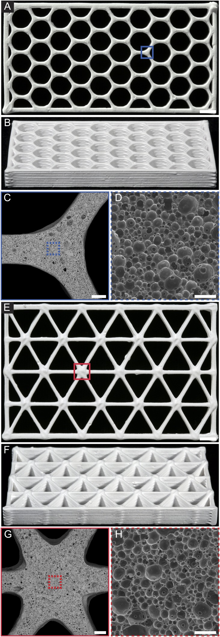
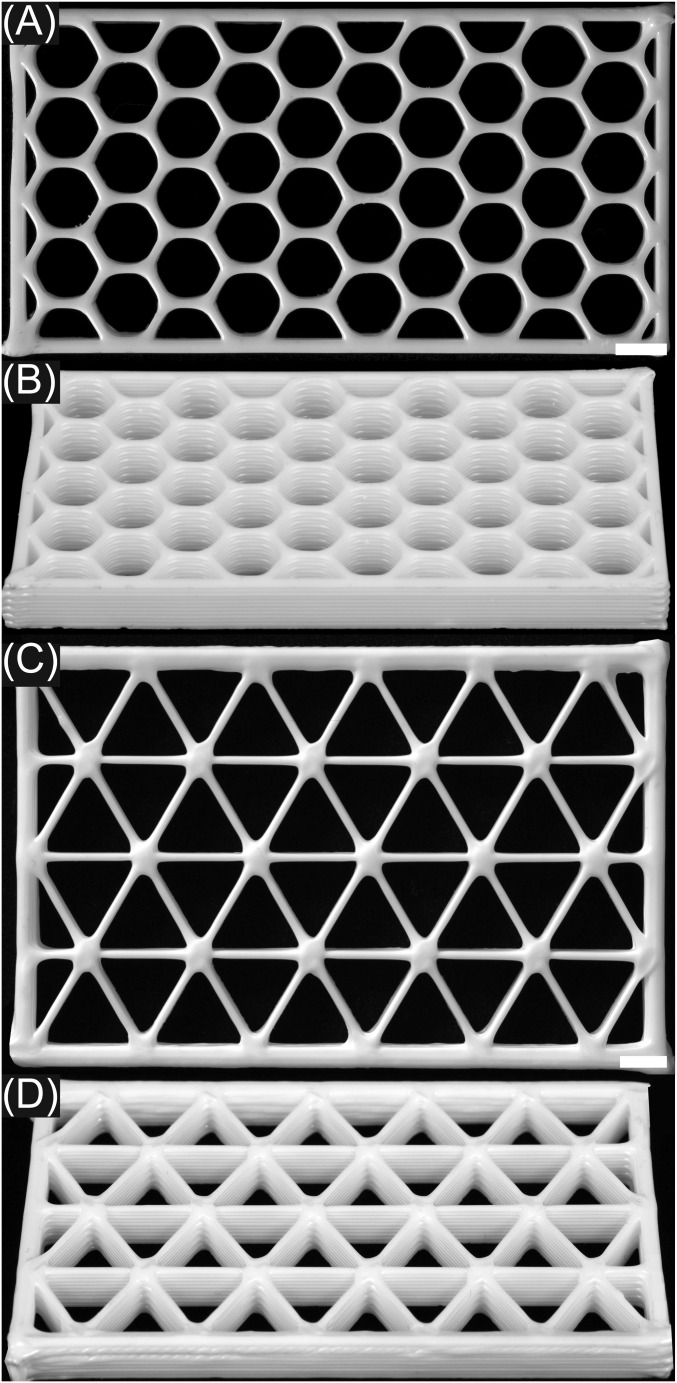
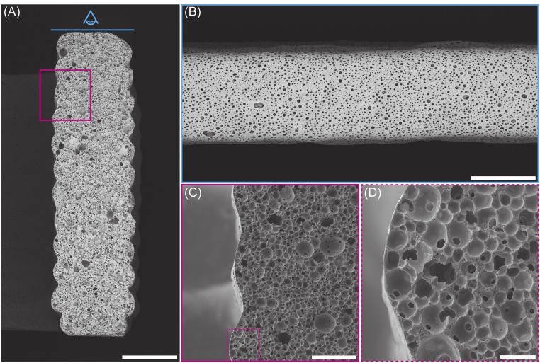
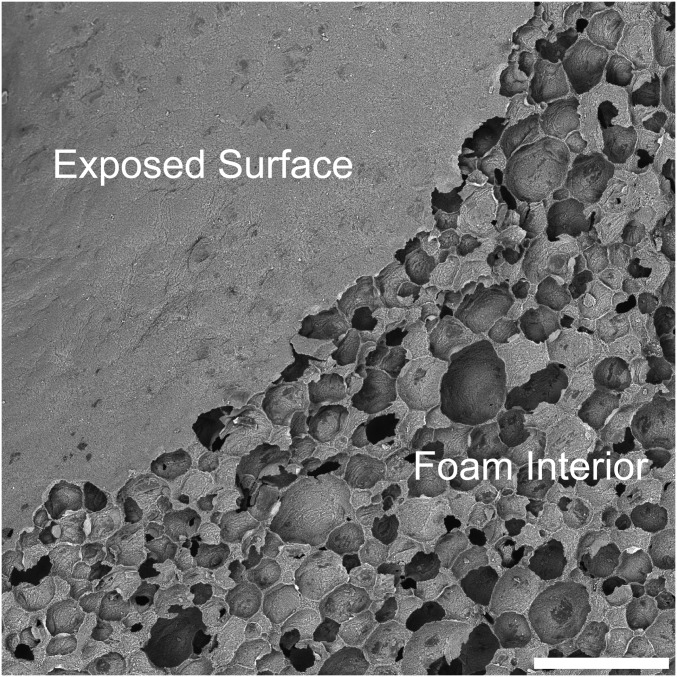
To show direct foam writing, we printed the PSF ink through a 610-μm-diameter nozzle at a constant volumetric flow rate of ∼1 mL/min to create bending-dominated hexagonal and stretching-dominated triangular honeycombs composed of bending-dominated closed foam struts (Fig. 3 and Movie S2). Note that these printing parameters reside within the stable printing regime delineated in Fig. 2C. The printed hexagonal honeycombs are 80 mm wide × 40 mm tall × 7.5 mm thick, whereas the triangular honeycombs are 83 mm wide × 53 mm tall × 7.3 mm thick. These sample dimensions are used to ensure equivalent relative density between honeycombs composed of the same strut microstructure but different cell geometries. As a control, we also printed honeycombs composed of pure colloidal ink (without bubbles) to create nearly dense alumina struts (Figs. S3 and S4). After printing, the honeycombs are dried under controlled humidity, bisque-fired to remove organic additives, and sintered at 1,500 °C. The observed shrinkage during drying and sintering yields highly porous hexagonal and triangular ceramic honeycombs with dimensions that are nominally 62 × 32 × 5.5 and 65 × 41 × 5.5 mm, respectively. Both printed geometries have relative densities of ρ*/ρstrut ∼ 28% and contain struts with ∼79–85% porosity (ρs/ρs-theory ∼ 15–21% relative density), yielding a net relative density of ρ*/ρs-theory ∼ 6%, where ρ*, ρstrut, ρs, and ρs-theory represent the densities of the printed honeycomb, the strut, the bulk material composing the honeycomb (i.e., sintered foam or nearly dense alumina) and theoretically, dense alumina, respectively. The nodes of each printed structure reveal seamless integration of printed filaments (Fig. 3 C and G) with foam microstructure that remains consistent between different honeycombs (Fig. 3 D and H). The printing process has a negligible effect on the foam microstructure within the filaments (Figs. S1 and S2). However, a dense skin is observed at the filament surface (Fig. S5), akin in morphology and thickness to the surface layer observed for the bulk cast foam (Fig. S6), as a consequence of surface area minimization (37).
Fig. 3.
3D porous ceramic honeycombs. (A and B) Representative sintered hexagonal honeycomb. (Scale bar: 5 mm.) (C) Image of one node of the hexagonal honeycomb and (D) the resulting microstructure. (Scale bars: C, 500 μm; D, 100 μm.) (E and F) Representative sintered triangular honeycomb. (Scale bar: 5 mm.) (G) Image of one node of the triangular honeycomb and (H) the resulting microstructure. (Scale bars: G, 500 μm; H, 100 μm.)
Fig. S3.
Optical images of representative printed nearly dense (A and B) hexagonal and (C and D) triangular honeycombs after sintering. (Scale bars: 5 mm.)
Fig. S4.
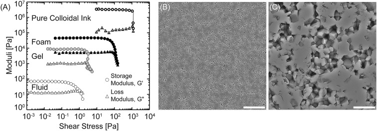
Pure colloidal ink rheology and microstructure after sintering. (A) Storage and loss moduli as a function of shear stress for the pure colloidal ink compared with the foam ink and its precursors. (B and C) Representative SEM images of the nearly dense ceramic microstructure after sintering at lower and higher magnifications, respectively. (Scale bars: B, 50 μm; C, 5 μm.)
Fig. S5.
Structure of printed foam filaments. Cross-sectional images of (A) foam honeycomb border, in which each printed foam filament possesses (B) a dense, thin skin surrounding (C and D) a highly porous, closed-cell interior. (Scale bars: A and B, 1,000 μm; C, 250 μm; D, 50 μm.)
Fig. S6.
SEM image of the external surface and interior of a molded and sintered foam structure, which reveals that skin formation is not unique to direct foam writing. (Scale bar: 200 μm.)
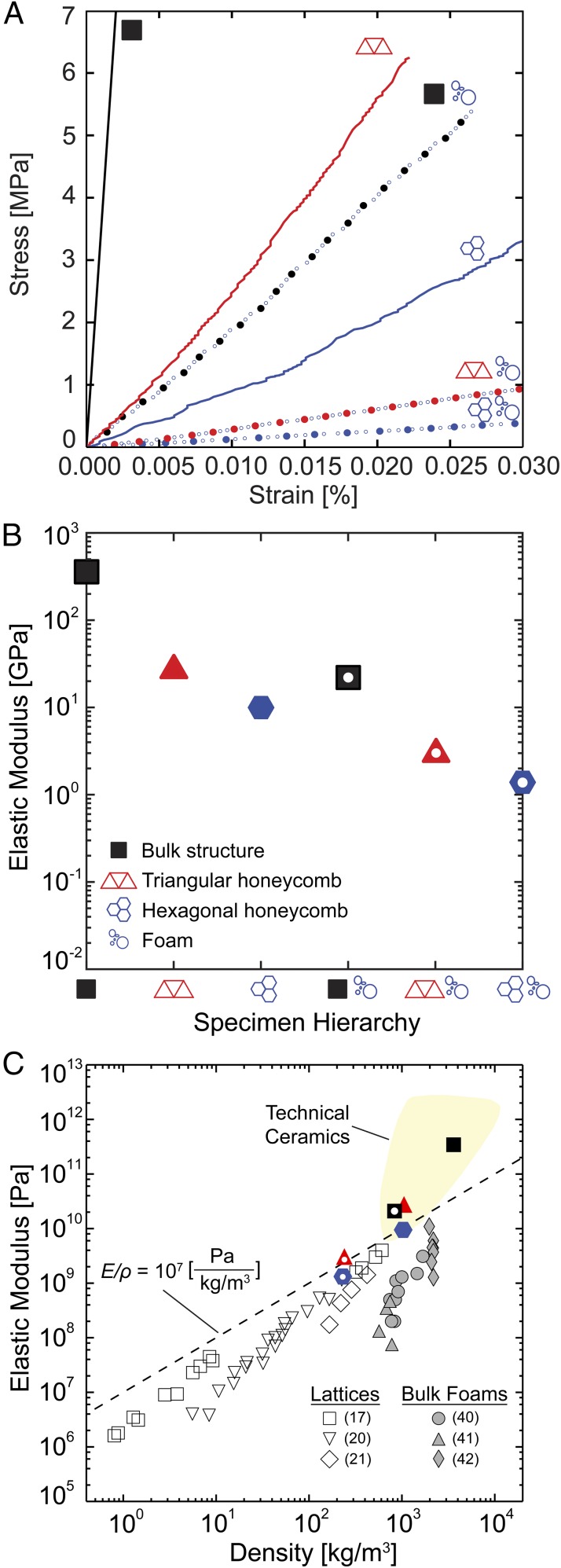
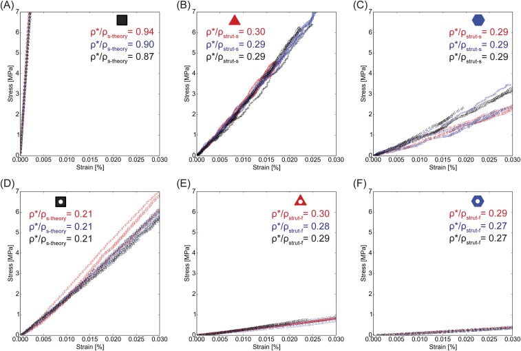
The sintered hexagonal and triangular ceramic honeycombs composed of both nearly dense struts (bending and stretching, respectively) and foam struts (bending–bending and stretching–bending, respectively) are nondestructively compressed in-plane to evaluate the influence of their printed microstructure and cell geometry on stiffness. Representative elastic stress–strain curves for each bulk material and honeycomb type are shown in Fig. 4 and Fig. S7. The elastic behavior of the honeycombs is well-predicted by
| [1] |
where E* is the honeycomb stiffness, Estrut is the strut stiffness, ρ* is the honeycomb density, ρstrut is the strut density, and B and b are unit cell-dependent loading constants. Note that B = 3/2 and 1/3 and b = 3 and 1 for hexagonal and triangular honeycombs, respectively (5, 38). Based on the relative densities of the nearly dense honeycombs (, where s corresponds to the nearly dense ceramic), the bending-dominated hexagonal honeycombs should be 36% as stiff as the stretching-dominated triangular ones. The measured elastic moduli of nearly dense hexagonal and triangular honeycombs are 9.9 ± 1.8 and 27.4 ± 1.0 GPa, respectively, which are within 1% of the predicted relative difference (Table S1). Both structures have knockdown factors less than 20% from their theoretical values based on the measured modulus of 344 ± 27 GPa for nearly dense alumina, which is determined by elastically compressing square bars.
Fig. 4.
Mechanical properties of the 3D ceramic architectures. (A) Stress as a function of strain (confined to the elastic region) for all printed structures. (B) Elastic modulus as a function of specimen hierarchy. (C) Plot of elastic modulus as a function of density that compares our printed architectures with other bulk alumina foams (40–42) and 3D periodic lattices produced by light-based 3D printing (17, 20, 21).
Fig. S7.
Elastic stress as a function of strain for (A) nearly dense bars, (B) nearly dense triangular honeycombs, (C) nearly dense hexagonal honeycombs, (D) foam bars, (E) triangular foam honeycombs, and (F) hexagonal foam honeycombs.
Table S1.
Summary of material properties
| Microstructure | Geometry | ρ, kg/m3 | Estrut, GPa | E* theory, GPa | E* measured, GPa | ||||
| Nearly dense | Bulk | — | 1 | 0.903 ± 0.04 | 0.903 | 3,585 | — | — | 344 ± 27 |
| Hexagonal honeycomb | 0.287 ± 0.003 | 1 | 0.903 ± 0.04 | 0.259 | 1,029 | 344 ± 27 | 12.2 | 9.9 ± 1.8 | |
| Triangular honeycomb | 0.293 ± 0.003 | 1 | 0.903 ± 0.04 | 0.265 | 1,050 | 344 ± 27 | 33.6 | 27.4 ± 1.0 | |
| Foam | Bulk | — | 1 | 0.210 ± 0.01 | 0.210 | 834 | — | — | 21.8 ± 1.2 |
| Hexagonal honeycomb | 0.275 ± 0.01 | 1 | 0.210 ± 0.01 | 0.058 | 229 | 21.8 ± 1.2 | 0.68 | 1.36 ± 0.06 | |
| Triangular honeycomb | 0.288 ± 0.01 | 1 | 0.210 ± 0.01 | 0.060 | 240 | 21.8 ± 1.2 | 2.09 | 3.04 ± 0.26 |
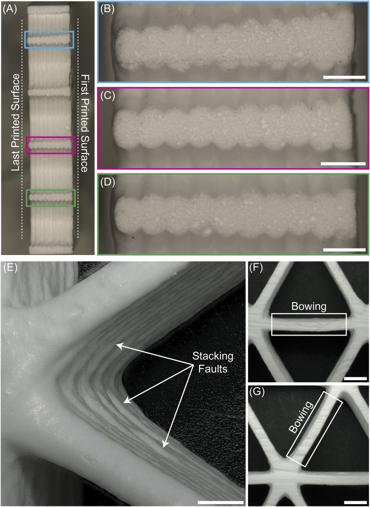
Equivalent compression measurements are carried out on ceramic honeycombs composed of foam struts. From their printed relative densities (, where f corresponds to foam) and the measured foam modulus of 21.8 ± 1.2 GPa, which is determined by elastically compressing square bars of closed-cell alumina foam, one predicts elastic moduli of 0.68 GPa for the hexagonal foam honeycomb and 2.09 GPa for the triangular foam honeycomb, indicating that the bending-dominated hexagonal structure should exhibit 33% of the stiffness of the stretching-dominated triangular honeycomb. The measured values are 1.36 ± 0.06 and 3.04 ± 0.26 GPa for each honeycomb, respectively. Increased stiffness for both architectures relative to model predictions may stem from underestimating ρ*/ρstrut-f because of thickness gradients in the cell walls (Fig. S8). Additionally, the hexagonal honeycomb modulus is 12% stiffer than expected relative to the triangular honeycomb. This observed difference likely arises because of the relative importance of defects (e.g., wall thickness variations, offset stacking between printed layers, and bent struts) (Fig. S8) on their stiffness. Such defects would have a more pronounced effect on the stiffness of triangular honeycombs, because their stretching behavior would be disrupted, thereby reducing their stiffness, compared with the hexagonal honeycombs (39). The ratio of the elastic moduli of the honeycombs with different strut microstructures illustrates the effect of strut hierarchy on elastic modulus and should vary according to and . However, the measured ratios of and are roughly double these predicted values, again likely because of underestimating ρ*/ρstrut-f. Nevertheless, the actual difference in stiffness between identical honeycomb geometries with different strut microstructures is nearly an order of magnitude in each case (Fig. 4 B and C).
Fig. S8.
Optical images of defects observed in the printed ceramic architectures. (A) Representative image of a through-thickness cross-section of one of the sintered foam hexagonal honeycombs. (B–D) The struts bisected by the cross-sectional cut show that the layers printed closer to the substrate can be thicker than the layers printed farther away from the substrate. Moreover, strut thickness and thickness gradient within a strut can vary within a given honeycomb. For instance, the strut in B is thicker than that in C and D, whereas B and C also show stronger thickness gradients compared with D. Variable strut thickness between layers is not captured in the relative density measurement, which may lead to increased honeycomb stiffness compared with model predictions based on the honeycomb density and properties of the solid foam. (Scale bars: 1 mm.) Furthermore, printed architectures may contain (E) stacking faults and (F and G) wall bowing. (Scale bars: E, 1 mm; F and G, 2.5 mm.)
Direct foam writing produces triangular foam honeycombs with higher specific stiffness [>107 Pa/(kg/m3)] and lower density (∼200 kg/m3) than bulk alumina foams produced by gelcasting PSFs (40), freeze-casting (41), or capillary suspensions (42) (Fig. 4C). Notably, our structures also possess superior specific stiffness at similar relative density compared with more exotic alumina lattices produced by other 3D printing methods (17, 20, 21) without the need for template removal or secondary coating steps. Although our experiments have focused on printing and characterizing hexagonal or triangular cells composed of a single foam microstructure and lattice density, the architecture–property space realizable via direct foam writing can be substantially broadened by varying (i) the bubble volume fraction within the foam ink and hence, microstructural porosity (β); (ii) strut aspect ratio (t/l); or (iii) cell geometry represented by a constant, C. For our unit cell geometries, the effects of these parameters on relative density are given by
| [2] |
where t is the strut thickness, l is the strut length, and C is for hexagonal honeycombs and for triangular honeycombs (5).
One current limitation of direct foam writing is the inability to pattern out of plane spanning features, such as octet trusses. However, this technique is well-suited for printing 3D woodpile lattices composed of foam struts (43). As an alternate motif, we created 3D woodpile lattices (Fig. S9) composed of hollow core foam-shell struts using a coaxial printhead, in which the PSF ink (shell) is coextruded with a fugitive wax core (44). These hollow core foam shell struts mimic natural structures, such as stems or quills, that rely on cross-sectional variations in material placement and microstructure to achieve their desired functionality (45).
Fig. S9.
Natural stem and printed 3D core shell architectures. (A) Cross-sectional image of a grass stalk. Reproduced with permission from ref. 44. (B) Top-down and (C) end-on images of a representative woodpile structure composed of filaments with foam shells and hollow cores (D). (Scale bars: A, 250 μm; B and C, 1,000 μm; D, 500 μm.)
In summary, we have created architected porous ceramics via direct writing of PSFs and characterized their mechanical properties. Solely by varying architecture (e.g., unit cell type and strut porosity), we systematically tuned the elastic modulus between ∼1 GPa for hexagonal honeycombs composed of foam struts to 27 GPa for triangular honeycombs composed of nearly dense struts. These ceramic honeycombs possess greater specific stiffness [>107 Pa/(kg/m3)] compared with micro- and nanoscale lattices of similar relative densities produced by other additive manufacturing methods. Given the generality and scalability of direct foam writing, it should be straightforward to pattern other ceramic, metal, and polymer foam-based inks with either closed or open cellular microstructures to further expand the applications realizable by this nascent approach.
Methods
PSF Inks.
The foam ink is created by first producing an aqueous colloidal suspension composed of 45% (vol/vol) α-alumina (mean particle size ∼ 300 nm, Brunauer–Emmett–Teller surface area ∼ 7.5 m2/g; AKP 30; Sumitomo Chemical) and deionized (DI) water at pH < 3 (the pH is adjusted by adding hydrochloric acid). The suspension is mixed in a planetary mixer (SpeedMixer DAC 600.2; FlackTek, Inc.) for 1 min at 800, 1,200, and 1,600 rpm and 7 min at 2,000 rpm to disperse the alumina, and ball milled for at least 48 h using 5-mm yttria-stabilized zirconia spherical milling media in a 2:1 mass ratio relative to the suspension. After ball milling, 4.8 μmol butyric acid (Sigma-Aldrich) is added per 1-m2 colloid surface area to partially hydrophobize the alumina particles. The suspension is then weakly gelled by adding sodium hydroxide (NaOH) until the pH is increased to 5–5.1. DI water, PEG (1 wt % relative to alumina; 20,000 g/mol; Sigma-Aldrich), and rice starch (2 wt % relative to water; HRICE 16; Hollander’s) are added to the gel before frothing to dilute the suspension to 35% (vol/vol) solids, strengthen printed structures, and retard drying, respectively. After each addition, the suspension is mixed for 2 min at 2,000 rpm. All frothing is performed in a 500-mL glass jar (SS CLR; VWR) using 75 g precursor gel. Air is introduced via a four-bladed impeller (316L Cross Stirrer; Scilogex) and overhead mixer (OS20-S; Scilogex) at 400, 500, 700, and 900 rpm for 2 min each and then, 1,000, 1,200, and 1,500 rpm for 5 min each. Final frothing is performed with a flat-bottomed whisk (Triangular 10.5-in Flat Bottom Whisk; Rattleware) at 1,200 rpm for 2 min in the presence of an air stream.
Pure Colloidal Ink.
To print nearly dense honeycombs, we created a pure (bubble-free) colloidal ink composed of 55% (vol/vol) α-alumina particles (AKP 30; Sumitomo Chemical) suspended in DI water and stabilized using 1 mg anionic polyelectrolye dispersant (Darvan 821a; R. T. Vanderbilt Company) per 1-m2 alumina surface area. The suspension is mixed at 1,700 rpm for 10 min to disperse the alumina particles. The solution is then ball milled for at least 48 h using 5-mm yttria-stabilized zirconia spherical milling media in a 2:1 mass ratio relative to the suspension. After milling, 7 mg hydroxypropyl methylcellulose (Methocel F4M; Dow Chemical Company) is added per 1 mL alumina in the form of a 5% (wt/wt) aqueous solution. The pH is adjusted to 7 using NaOH or nitric acid as necessary, and the suspension is diluted to 51% (vol/vol) alumina with DI water. After the addition of each ingredient, the suspension is mixed for 2 min at 1,700 rpm.
Contact Angle Measurements.
Static contact angle measurements are carried out by depositing 10-μL drops at an infill rate of 60 μL/min onto the surface of the dried precursor gel. The reported value of 59° ± 5° represents the average and SD obtained from seven separate measurements.
Rheological Characterization.
The rheological properties of the fluid, gel, and foam inks are characterized at 21 °C using a controlled stress rheometer (Discovery HR-3 Hybrid Rheometer; TA Instruments). A 40-mm tapered cone geometry (2.005°, 56-μm truncation gap) is used for the fluid and gel, whereas a custom-made eight-bladed vane (15-mm diameter, 38.5-mm height, 1.3-mm blade thickness, and 40-mm gap) is used to quantify foam and pure colloidal ink properties. Flow sweeps are performed between 1e-3 and 400 s−1. Oscillatory measurements are performed at 10 rad/s between 1e-4 and 10% strain.
Foam Ink Printability.
Stable printing conditions are determined by extruding the foam through nozzles of varying diameter sat different volumetric flow rates corresponding to an effective print speed (νeff) ranging between 1 mm/s and 10 m/s. The extruded material was collected and analyzed (Methods, Porosity Measurements). Effective print speed (νeff) corresponds to the print speed required to deposit a filament of equivalent diameter to the nozzle of interest at a given ink volumetric flow rate: , where Q is the volumetric flow rate, and d is the nozzle diameter.
Direct Writing of Architected Cellular Ceramics.
Foam-based structures are printed by depositing a foam ink, which is loaded into a 60-mL syringe and dispensed using a syringe pump (PHD Ultra; Harvard Apparatus), through either a 610-μm- (honeycombs) or 1.19-mm-diameter (square bars) tapered nozzle (Nordson EFD). The printed parts are formed by translating the ink-filled syringe in the prescribed path using a custom-built 3D printer (ABG 10000; Aerotech Inc.). All print paths are created by writing the appropriate G-code commands. The foam-based hexagonal and triangular honeycombs are printed at 48 and 24 mm/s, respectively. The bulk foam bars are printed at 30 mm/s with a flow rate of 2 mL/min into a 4 × 4 × 90-mm shape. The ink is printed onto a wax (Pure Petroleum Jelly; Vaseline)-covered zirconia setter plate (Zircoa). Immediately after printing, the structures are placed into a box with controlled humidity and dried for at least 1 wk, after which the structures are removed and allowed to dry at ambient conditions for at least 24 h. After drying, the structures are removed from the printing substrate and placed on a separate setter plate. Residual moisture is removed by heating at 70 °C for 2 h, 90 °C for 4 h, and 110 °C for 24 h with ramp rates of 0.5 °C/min, after which binder burnout is performed according to the following schedule: 200 °C for 20 h, 300 °C for 20 h, 500 °C for 20 h, and 700 °C for 20 h. After binder removal is complete, the structures are sintered at 1,500 °C for 3 h. The respective heating and cooling rates are 1 and 2 °C/min in each case.
Nearly dense structures are printed by depositing the pure colloidal ink, which is loaded into a 30-mL syringe and dispensed using a positive displacement pump (Ultra 2800; Nordson EFD), through either a 610-μm (honeycombs) or 1.36-mm-diameter (bars) tapered nozzle using the same print setup and substrate as the foam ink. The ink flow rate for both honeycombs is 0.53 mL/min. Hexagonal and triangular honeycombs are printed 36 and 18 mm/s, respectively. The print parameters and shape of the bulk foam bars are also used for the bulk nearly dense bars. Immediately after printing, the structures are placed into a box with controlled humidity and dried for 3 h, after which they are immersed in oil for 2 wk or until they become rigid enough to handle. After oil immersion, the honeycombs are dried at ambient conditions for 24 h, prefired, and sintered following the same heat treatment process as described above for the foam structures.
Mechanical Characterization.
Foam honeycombs and bulk foam bars as well as nearly dense honeycombs and bulk nearly dense bars are compressed at constant cross-head speeds of 0.025 (Model 4201; Instron), 0.05 (Model 4201; Instron), 0.12 (Model 4201; Instron), and 0.12 mm/min (Model 1321; Instron), respectively. Force measurements for the foam honeycombs and bulk foam bars and their nearly dense counterparts are performed with 500-N, 5,000-N, and 50-kN load cells, respectively. Deflections for all structures except the nearly dense square bars are captured by a digital contact probe (GT2-P12K; Keyence) mounted in a custom bracket. The deflection of bulk nearly dense specimens is measured with a contact extensometer (2630-104; Instron). To minimize friction effects, both the bulk foam and bulk nearly dense compression specimens are in the form of square bars with an aspect ratio of at least eight. All specimens are ground, such that the faces contacting the compression platens are flat and parallel within 5 μm. The vertical boundaries of each honeycomb are removed before testing to eliminate all noncellular load-bearing material. At least three specimens of each type are tested. Each specimen is tested three times. Reported averages and SDs are calculated from the mean stiffness value of each specimen. Modulus values for each test are obtained from linear regressions of the data. All tests are included in the reported results.
Porosity Measurements.
Porosity is measured by image analysis using the systematic point count method (ASTM E562-08). At least 1,000 grid points are analyzed over 19.5 mm2 for each wet foam microstructure, and at least 700 grid points over 1.5 mm2 are analyzed for each sintered architecture. Their mean pore size is obtained using the linear intercept method for two-phase materials (ASTM E112-13), where bubbles (or pores) are defined as the dispersed phase and the alumina suspension or sintered alumina matrix is defined as the continuous phase. For wet foams, at least 60 mm of lines are analyzed over 19.5 mm2. For sintered specimens, 30 mm of lines are analyzed over 1.5 mm2.
Density Measurements.
To nondestructively measure the relative density of the printed and sintered honeycombs, in-plane images of the full honeycomb are taken against a black background and thresholded to obtain the areal coverage of the top surface of the printed structure (ρ*/ρstrut). The boundaries of the honeycombs are not included in the analysis, such that only the load-bearing parts of the structures contribute to relative density. Images are taken from the top side of the honeycomb to minimize the contribution of the initially printed layers (approximately layers 1–3), which frequently had somewhat higher relative densities because of substrate effects (Fig. S8). For bulk structures, the relative density is calculated according to their mass and volume, where the volume is determined using the Archimedes’ method. The net relative density of the honeycombs (ρ*/ρs-theory) is calculated by, where ρs-theory is the theoretical density of alumina (3.97 g/cm3); 1, because the honeycomb microstructures are assumed to be the same as those of their respective bulk materials (i.e., sintered foam and nearly dense alumina); 0.903 for nearly dense structures; and 0.210 for foam structures. For the nearly dense material is <1 (Fig. S4), whereas is equivalent to 1 – β for foam structures. The values for each of these parameters are provided in Table S1.
Supplementary Material
Acknowledgments
We acknowledge imaging and video assistance by Dr. James Weaver and Dr. Lori Sanders and experimental assistance by Michael Kreder (Aizenberg Laboratory). We also acknowledge support from National Science Foundation Grant DMR 1305284, the National Science Foundation Graduate Research Fellow Program (J.T.M.), the Harvard Materials Research and Engineering Center Research Experience for Undergraduates Program (L.W.), and the Matoula S. Salapatas Professorship in Materials Science and Engineering at the Massachusetts Institute of Technology (P.G.D. and L.J.G.). J.A.L. acknowledges support from the Vannevar Bush Faculty Fellowship Program sponsored by the Basic Research Office of the Assistant Secretary of Defense for Research and Engineering and funded by Office of Naval Research Grant N00014-16-1-2823.
Footnotes
Conflict of interest statement: J.T.M. and J.A.L. have filed a patent on this work. J.A.L. has cofounded a company, Voxel8, which focuses on 3D printing of electronics. The work described in this manuscript has not been licensed by Voxel8.
This article is a PNAS Direct Submission. V.D. is a Guest Editor invited by the Editorial Board.
This article contains supporting information online at www.pnas.org/lookup/suppl/doi:10.1073/pnas.1616769114/-/DCSupplemental.
References
- 1.Gibson LJ, Ashby MF, Harley BA. Cellular Materials in Nature and Medicine. Cambridge Univ Press; Cambridge, UK: 2010. [Google Scholar]
- 2.Wegst UGK, Bai H, Saiz E, Tomsia AP, Ritchie RO. Bioinspired structural materials. Nat Mater. 2015;14(1):23–36. doi: 10.1038/nmat4089. [DOI] [PubMed] [Google Scholar]
- 3.Meyers MA, McKittrick J, Chen P-Y. Structural biological materials: Critical mechanics-materials connections. Science. 2013;339(6121):773–779. doi: 10.1126/science.1220854. [DOI] [PubMed] [Google Scholar]
- 4.Fratzl P, Weinkamer R. Nature’s hierarchical materials. Prog Mater Sci. 2007;52(8):1263–1334. [Google Scholar]
- 5.Fleck NA, Deshpande VS, Ashby MF. Micro-architectured materials: Past, present and future. Proc R Soc Lond A Math Phys Sci. 2010;466(2121):2495–2516. [Google Scholar]
- 6.Gibson LJ. The hierarchical structure and mechanics of plant materials. J R Soc Interface. 2012;9(76):2749–2766. doi: 10.1098/rsif.2012.0341. [DOI] [PMC free article] [PubMed] [Google Scholar]
- 7.Gibson LJ, Easterling KE, Ashby MF. The structure and mechanics of cork. Proc R Soc Lond A Math Phys Sci. 1981;377(1769):99–117. [Google Scholar]
- 8.Karam GN, Gibson LJ. Biomimicking of animal quills and plant stems: Natural cylindrical shells with foam cores. Mater Sci Eng C Mater Biol Appl. 1994;2(1–2):113–132. [Google Scholar]
- 9.Prum RO, Torres RH, Williamson SJD. Coherent light scattering by blue feather barbs. Nature. 1998;396(6706):28–29. [Google Scholar]
- 10.Weinkamer R, Fratzl P. Solving conflicting functional requirements by hierarchical structuring—Examples from biological materials. MRS Bull. 2016;41(9):667–671. [Google Scholar]
- 11.Deville S. Freeze-casting of porous ceramics: A review of current achievements and issues. Adv Eng Mater. 2008;10(3):155–169. [Google Scholar]
- 12.Gonzenbach UT, Studart AR, Tervoort E, Gauckler LJ. Ultrastable particle-stabilized foams. Angew Chem Int Ed Engl. 2006;45(21):3526–3530. doi: 10.1002/anie.200503676. [DOI] [PubMed] [Google Scholar]
- 13.Chuanuwatanakul C, Tallon C, Dunstan DE, Franks GV. Producing large complex-shaped ceramic particle stabilized foams. J Am Ceram Soc. 2013;96(5):1407–1413. [Google Scholar]
- 14.Klotz M, Amirouche I, Guizard C, Viazzi C, Deville S. Ice templating—An alternative technology to produce micromonoliths. Adv Eng Mater. 2012;14(12):1123–1127. [Google Scholar]
- 15.Munch E, Saiz E, Tomsia AP, Deville S. Architectural control of freeze-cast ceramics through additives and templating. J Am Ceram Soc. 2009;92(7):1534–1539. [Google Scholar]
- 16.Zheng X, et al. Multiscale metallic metamaterials. Nat Mater. 2016;15(10):1100–1106. doi: 10.1038/nmat4694. [DOI] [PubMed] [Google Scholar]
- 17.Zheng X, et al. Ultralight, ultrastiff mechanical metamaterials. Science. 2014;344(6190):1373–1377. doi: 10.1126/science.1252291. [DOI] [PubMed] [Google Scholar]
- 18.Schaedler TA, et al. Ultralight metallic microlattices. Science. 2011;334(6058):962–965. doi: 10.1126/science.1211649. [DOI] [PubMed] [Google Scholar]
- 19.Meza LR, et al. Resilient 3D hierarchical architected metamaterials. Proc Natl Acad Sci USA. 2015;112(37):11502–11507. doi: 10.1073/pnas.1509120112. [DOI] [PMC free article] [PubMed] [Google Scholar]
- 20.Meza LR, Das S, Greer JR. Strong, lightweight, and recoverable three-dimensional ceramic nanolattices. Science. 2014;345(6202):1322–1326. doi: 10.1126/science.1255908. [DOI] [PubMed] [Google Scholar]
- 21.Bauer J, Hengsbach S, Tesari I, Schwaiger R, Kraft O. High-strength cellular ceramic composites with 3D microarchitecture. Proc Natl Acad Sci USA. 2014;111(7):2453–2458. doi: 10.1073/pnas.1315147111. [DOI] [PMC free article] [PubMed] [Google Scholar]
- 22.Eckel ZC, et al. Additive manufacturing of polymer-derived ceramics. Science. 2016;351(6268):58–62. doi: 10.1126/science.aad2688. [DOI] [PubMed] [Google Scholar]
- 23.Smay JE, Cesarano J, Lewis JA. Colloidal inks for directed assembly of 3-D periodic structures. Langmuir. 2002;18(14):5429–5437. [Google Scholar]
- 24.Ahn BY, et al. Printed origami structures. Adv Mater. 2010;22(20):2251–2254. doi: 10.1002/adma.200904232. [DOI] [PubMed] [Google Scholar]
- 25.Tao P, et al. Bioinspired engineering of thermal materials. Adv Mater. 2015;27(3):428–463. doi: 10.1002/adma.201401449. [DOI] [PubMed] [Google Scholar]
- 26.Hollister SJ. Porous scaffold design for tissue engineering. Nat Mater. 2005;4(7):518–524. doi: 10.1038/nmat1421. [DOI] [PubMed] [Google Scholar]
- 27.Parlett CM, Wilson K, Lee AF. Hierarchical porous materials: Catalytic applications. Chem Soc Rev. 2013;42(9):3876–3893. doi: 10.1039/c2cs35378d. [DOI] [PubMed] [Google Scholar]
- 28.Chabi S, Peng C, Hu D, Zhu Y. Ideal three-dimensional electrode structures for electrochemical energy storage. Adv Mater. 2014;26(15):2440–2445. doi: 10.1002/adma.201305095. [DOI] [PubMed] [Google Scholar]
- 29.Binks BP. Particles as surfactants - Similarities and differences. Curr Opin Colloid Interface Sci. 2002;7(1):21–41. [Google Scholar]
- 30.Aveyard R, Binks BP, Clint JH. Emulsions stabilised solely by colloidal particles. Adv Colloid Interface Sci. 2003;100:503–546. [Google Scholar]
- 31.Pickering SU. CXCVI. - Emulsions. J Chem Soc Trans. 1907;91(23):2001–2021. [Google Scholar]
- 32.Finkle P, Draper HD, Hildebrand JH. The theory of emulsification. J Am Chem Soc. 1923;45(12):2780–2788. [Google Scholar]
- 33.Schulman JH, Leja J. Control of contact angles at the oil-water-solid interfaces. Emulsions stabilized by solid particles (BaSO4) Trans Faraday Soc. 1954;50:598–605. [Google Scholar]
- 34.Gonzenbach UT, Studart AR, Steinlin D, Tervoort E, Gauckler LJ. Processing of particle-stabilized wet foams into porous ceramics. J Am Ceram Soc. 2007;90(11):3407–3414. [Google Scholar]
- 35.Studart AR, Gonzenbach UT, Tervoort E, Gauckler LJ. Processing routes to macroporous ceramics: A review. J Am Ceram Soc. 2006;89(6):1771–1789. [Google Scholar]
- 36.Conrad JC, Lewis JA. Structure of colloidal gels during microchannel flow. Langmuir. 2008;24(15):7628–7634. doi: 10.1021/la800919k. [DOI] [PubMed] [Google Scholar]
- 37.Banhart J. Manufacturing routes for metallic foams. JOM. 2000;52(12):22–27. [Google Scholar]
- 38.Gibson LJ, Ashby MF. Cellular Solids: Structure and Properties. Cambridge Univ Press; Cambridge, UK: 1997. [Google Scholar]
- 39.Compton BG, Lewis JA. 3D-printing of lightweight cellular composites. Adv Mater. 2014;26(34):5930–5935. doi: 10.1002/adma.201401804. [DOI] [PubMed] [Google Scholar]
- 40.Tallon C, Chuanuwatanakul C, Dunstan DE, Franks GV. Mechanical strength and damage tolerance of highly porous alumina ceramics produced from sintered particle stabilized foams. Ceram Int. 2015;42(7):8478–8487. [Google Scholar]
- 41.Bouville F, Maire E, Deville S. Lightweight and stiff cellular ceramic structures by ice templating. J Mater Res. 2014;29(2):175–181. [Google Scholar]
- 42.Dittmann J, Willenbacher N. Micro structural investigations and mechanical properties of macro porous ceramic materials from capillary suspensions. J Am Ceram Soc. 2014;97(12):3787–3792. [Google Scholar]
- 43.Minas C, Carnelli D, Tervoort E, Studart AR. 3D Printing of Emulsions and Foams into Hierarchical Porous Ceramics. Adv Mater. 2016;28(45):9993–9999. doi: 10.1002/adma.201603390. [DOI] [PubMed] [Google Scholar]
- 44.Dawson MA, Gibson LJ. Optimization of cylindrical shells with compliant cores. Int J Solids Struct. 2007;44(3):1145–1160. [Google Scholar]
- 45.Gibson LJ, Ashby MF, Karam GN, Wegst UGK, Shercliff HR. The mechanical properties of natural materials. II. Microstructures for mechanical efficiency. Proc R Soc Lond A Math Phys Sci. 1995;450(1938):141–162. [Google Scholar]
Associated Data
This section collects any data citations, data availability statements, or supplementary materials included in this article.


