Abstract
Context:
Asymmetry and unfavorable esthetics of the jawline have become possible to correct in three dimensions using computer aided design and computer aided manufacturing.
Aims:
The aim of this study was to provide esthetic, technical, and operative guidelines for mandibular angle and border augmentation using patient-specific titanium implants made by selective laser melting.
Settings and Design:
University hospital - prospective registry.
Subjects and Methods:
Twelve patients and 17 implantation sites were documented and prospectively registered. Malformational, deformational, and purely esthetic indications were encountered.
Statistical Analysis Used:
Descriptive.
Results:
Patient satisfaction was high, probably because the patients had input into the planned dimensions and shape. A serious infection with implant removal occurred in one patient who had six previous surgeries at the same sites. Technical and surgical guidelines were developed including splitting implants into two segments when the mental nerve was at risk, using a three-dimensional (3D) puzzle connection, providing at least two screw holes per segment, using scaffolds at the bony contact side, using a “satin” finish at the periosteal side, referring to anatomical structures where possible, making provisions for transbuccal and transoral fixation, using a high vestibular incision, and using a double-layer closure. Esthetic guidelines are discussed but could not be upgraded.
Conclusions:
Mirroring techniques and 3D print accuracy up to 0.1 mm allow precise planning of jaw angle implants. Patients are pleased when given preoperative renderings for their consideration. Infections can be managed using technical and operative recommendations and careful patient selection.
Keywords: Mandible, patient-specific modeling, prostheses and implants
INTRODUCTION
Little has been published over the last 25 years on achieving mandibular jawline definition with implants.
Whitaker advocated the use of Teflon/carbon implants (Proplast®, Vitex, Houston, TX, USA) that are subperiosteally placed, lateral to the angle, and without screw fixation.[1] Aiache described silicone implants available in three sizes that are anatomically carved to the case and placed subperiosteally without screw fixation.[2] In contrast to Whitaker, Aiache lengthened the vertical ramus by having the implant straddle the lower border.[1,2] Semergidis et al. described a series of 18 patients in whom a submandibular approach was used to place porous ethylene implants (Medpore®, Stryker, Kalamazoo, MI, USA) that also increased posterior height and were transbuccally fixed with two to three screws.[3] The pterygomasseteric sling was reconstructed on closure, but the final results were not quantified. Yaremchuk described a series of 11 cases with transorally placed porous ethylene implants (Medpore®), also increasing posterior height and using transbuccal screw fixation.[4] Bastidas and Zide warned against vertical lengthening, frankly stating that “the masseter cannot be lengthened.”[5] They felt that porous polyethylene or silicone implants should not be placed through a facelift incision or Risdon approach, as the pterygomasseteric sling will be disrupted, causing the masseter to bulge on clenching and exposing the lower border of the implant (also demonstrated by Thomas and Yaremchuk[6]). They too advocated screw fixation. Even with the advantage of screw fixation, asymmetrical results and infectious complications remain issues for many facial surgeons and are reasons not to perform implantation at this visible site.
With the advent of additive manufacturing, software is now available that allows precise preoperative design on segmented computerized tomography data using mirroring techniques (3-matic®, Materialise, Heverlee, Belgium; Geomagic Freeform Plus®, 3D Systems, Darmstadt, Germany). This is particularly useful for bilateral esthetic features such as jaw angles and jawlines. The aim of this study was to present clinically interesting design requirements for jawline demarcation using titanium implants manufactured by selective laser melting (SLM).
SUBJECTS AND METHODS
Preoperative planning
Anthropometrical guidelines
Assessing abnormalities and planning corrections are not easy tasks when a patient presents with symmetrical hypoplasia. A proper substrate is missing. Constructs can be made on frontal and profile clinical pictures of a face and compared with ideal proportions and inclinations. Contemporary guidelines exist for men, not for women.[7]
For female patients, another approach is more attractive. Women can usually describe which celebrity's angle or jawline they desire. If the surgeon is lucky, a pure profile or frontal picture of that celebrity is available on the Internet. The patient's and celebrity's pictures can be superimposed, and the difference provides an idea of the desired corrections, even down to the millimeter [Figure 1].[8] Soft-to-hard tissue ratios have not been published for this sensitive three-dimensional (3D) area. We simply assume that 1 mm of hard tissue augmentation results in 1 mm of soft tissue augmentation in lateral and vertical directions. This has to be handled with caution, but it provides at least an impression that can be discussed with the patient.
Figure 1.
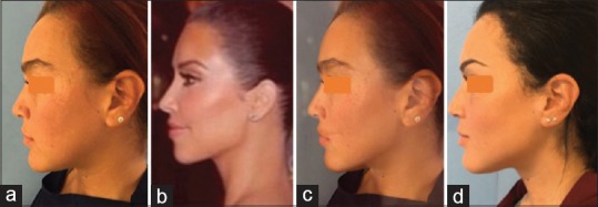
Photoshop simulation (c) of the jaw angle of Kim Kardashian (b) onto a patient's original facial profile (a) After jaw angle implantation (d) (Courtesy Dr. N. Loomans)
Technical design guidelines
Fibrosis and a scarred buccal vestibule from multiple orthognathic, reconstructive, and/or implantation surgeries may prompt a surgeon to access the mandibular border through a submandibular approach. In the present series, the author was not tempted or urged to do so. When choosing the transoral route, maximal interincisal mouth opening, reduced intercommissure width, and reduced lip elasticity may pose a problem when considering voluminous implants. This is often the case in hemifacial microsomia patients for whom orthognathic surgery, ramus reconstruction, and macrostomia correction have been previously undertaken.[9] Inserting voluminous implants may also jeopardize the mental nerve, especially when they extend below the mental foramen. For both of these reasons, splitting the implant in two parts may be considered. The posterior and anterior segments can be positioned with a front-to-back and back-to-front action, respectively. The tip of the implant is slipped under the mental foramen after subperiosteal dissection of this area has been undertaken through the extension of the buccal incision into the labial vestibule [Figure 2].
Figure 2.
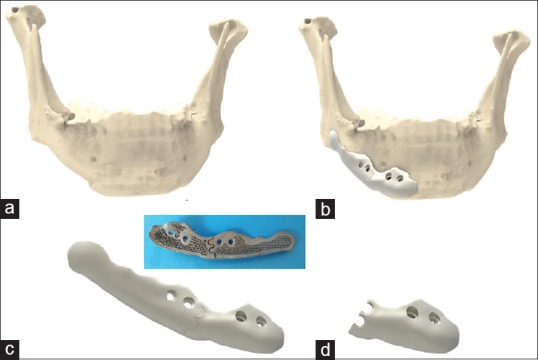
Rendering of a two-part implant on the lateral mandibular border extending below the mental foramen (Geomagic Freeform Plus®) (a) mandibular shape after two orthognathic surgeries and one chin osteotomy, (b) implant design in two parts, (c) connected double three-dimensional puzzle design, (d) anterior part showing the disconnected double three-dimensional puzzle design, (e) Backside of the three-dimensional printed and biofunctionalized assembly, with three-dimensional puzzle design
Precise reassembling of the two segments within the wound cavity is best performed with an interlocking design, such as a 3D puzzle connection.[10] The use of one or two 3D puzzle connections does not make a difference in the author's experience [Figure 2]. However, an oversized 3D design may hamper insertion of the second segment because more lateral soft tissue stretch is required [Figure 3].
Figure 3.
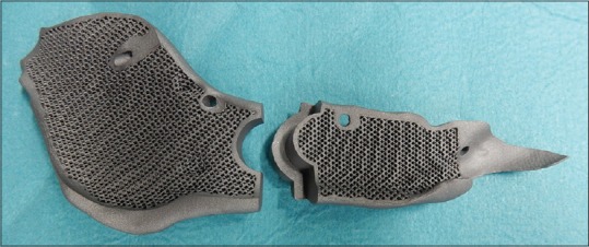
Medial part of a left-sided jaw border implant in two parts with a large three-dimensional puzzle design. Each part has two holes for screw fixation. The scaffolding is clearly visible
Mirroring a healthy side to a deficient one may prompt the designer to simulate the cranial part accordingly large. This is less important for jawline definition and may be the cause of wound dehiscence, so it is wise to compromise.
The implant may straddle the lower border halfway; however, the surgeon should not be forced to strip the pterygomasseteric sling to set the implant tight on the border.
Porosities (scaffolding) are useful where there is bony contact [Figure 4]. The friction provides primary stability as with any screw-fixed plate.[11] Porosities >500 µm are osteoinductive. Fukuda et al. demonstrated osteoinduction as deep as 5 mm in channels with a diameter of 500 µm or more within SLM-manufactured titanium implants placed in a nonosseous site, namely, the dorsal muscles of Beagle dogs.[12] Scaffolding increases the overall elasticity to more closely approximate that of bone[13] and therefore reduces stress shielding and premature loosening of an implant fixed to the weight-bearing mandible. It also helps in weight reduction. Hence, it makes sense to biofunctionalize the area of bony contacts using scaffolds with a diamond unit cell structure ≥500 µm for a few millimeters deep. Sandblasting and acid etching further promote osteoconductivity.[14]
Figure 4.
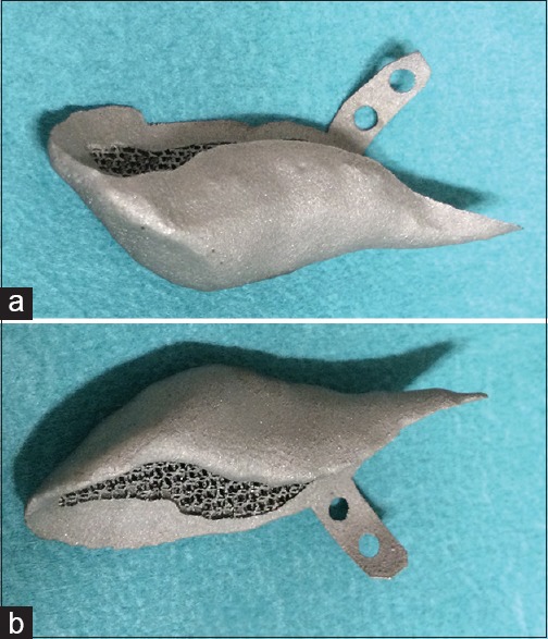
Left (a) and right (b) single-piece jaw implants designed to extend inferiorly. The extension lips each have two screw holes. Porosities are provided where bone will come in contact. The periphery and lateral surface is “satin” finished to prevent contamination from saliva
The lateral surface is micro-shot-peened (250-µm Al2O3 broken beads) to obtain a satin” finish with a roughness average of N7–N10. A highly polished surface may discourage periosteum reattachment, whereas a very rough surface may encourage bacterial growth when contamination with saliva occurs.[15]
Two screws per implant segment are necessary for proper fixation. Masseter muscle action may otherwise dislocate the posterior segment. In the author's experience, a single screw in an anterior segment may not prevent rotation. The screw holes are designed with respect to the inferior alveolar nerve using image segmentation software (Mimics Medical 19.0, Mimics Innovation Suite, Materialise, Heverlee, Belgium). Depending on the location of the implant and the estimated freedom of access, screw holes are provided in the implant body or lip extensions [Figure 4]. The extensions are also used to refer to anatomical structures (e.g., molars) for improved initial orientation. When in the jaw angle area, the author recommends providing holes for both the transoral and transbuccal approach, with the latter as a rescue measure [Figure 5]. Countersinking is not required. The author prefers screws with external pentagon-shaped heads (2.3-mm diameter; Surgi-Tec NV, Gent, Belgium) that facilitate screw removal during placement or eventually on explantation.
Figure 5.
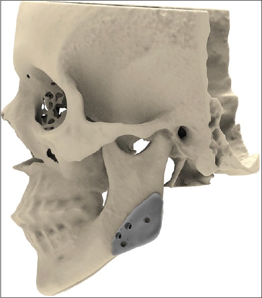
Planning of screw hole placement below the mandibular canal: The upper and lower sets are for transoral and transbuccal fixation, respectively. (Rendering of skull and right-sided implant of patient of Figure 1)
Although implant augmentation of the chin initially seems to be a logical extension of the lateral augmentation, the author prefers a chin osteotomy when chin augmentation is required. With an osseous genioplasty, height reduction can also be obtained. With the advancement of the lower mandibular border, the digastric and geniohyoid muscles are stretched with a positive functional (increase of airway) and esthetic (decrease of mentocervical angle) effect on hyoid position. Jawline augmentation with titanium implants and chin osteotomy can be done simultaneously [Figure 6].
Figure 6.
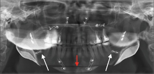
A rescue orthognathic case after bimaxillary surgery and condylar resorption with loss of jaw angle definition and increased anterior facial height. Jaw angle reconstruction was performed together with a chin osteotomy (red arrow) with advancement and height reduction. The extension lips are depicted (white arrows) with reference to the distal side of the last molars
The choice of titanium over polyetheretherketone (PEEK) is based on the European belief that it is better to prevent long-term complications caused by nonosseointegrated PEEK implants than to handle those complications associated with osseointegrated titanium (Federal and Drug Administration philosophy).
Operative technique
The intraoral approach to the jaw angle is made with an incision based on the external oblique line, extending anteriorly, staying 1 cm above the lower recess of the vestibule, and avoiding the long buccal nerve. Anterior extension continues into the lower lip when the jowl area also needs correction or when voluminous angle implants are placed. A high incision is likely to minimize postoperative saliva spillage into the wound. Watertight closure of the oral mucosal membrane is difficult to guarantee.
Enlarging the wound cavity for augmentation inferior and/or posterior to the mandibular border can be performed by dry gauze packing rather than with sharp dissection. Uniform expansion with gauze will lead to periosteum distention and pocket formation rather than perforations. This protects the mandibular branch of the facial nerve in hemifacial microsomia cases, where its course is unpredictable. It also prevents opening the superficial neck to the oral cavity.
Intraoperative 3D imaging (e.g., with the BV Pulsera Fluoroscopy System, Philips Medical, Eindhoven, The Netherlands) will confirm correct positioning.
Infection control is further maintained by copious wound rinsing, rinsing the implant in rifampicin solution, double-layer closure (i.e., horizontal running mattress suture for deep approximation and eversion, superficial running for the epithelial border approximation), application of fibrin glue (Tisseel, Baxter) under the suture line, and 5 days of penicillin perorally.
RESULTS
The guidelines described in section 2 resulted from the author's experience with this small group. Two male patients insisted on having larger implants than originally designed. Postoperatively, one was pleased with the results, whereas the other admitted to having underestimated the result. No revisions were required to correct design errors. In the end, all patients were satisfied.
Complications arose in three patients. One had already undergone several operations (i.e., three orthognathic surgeries and one alloplastic jaw angle implantation with two revision surgeries), each time with an intraoral vestibular incision. The titanium implants were big, and wound dehiscence and infection occurred. The implants were removed, and a smaller set will be inserted through a Risdon approach. A wound dehiscence also occurred in a hemifacial microsomia case, which caused no frank infection and was permanently closed during the gluteal fat transplantation[9] and macrostomia correction 3 months later. In one patient, a small implant segment rotated around a single screw fixation, necessitating correction 1 week later using local anesthesia only.
No permanent sensory disorders were observed.
DISCUSSION
Hemifacial microsomia and (revisional) orthognathic surgery patients comprise two common indications for jaw angle and jawline augmentation. Both are easily planned with mirroring techniques using the commercially available image-processing software. Esthetic augmentation is more challenging [Figure 7]. One side has to be designed “de novo,” and the patient's perception of their ideal jaw definition must be conveyed to the surgeon and designer. A titanium implant is then an all-or-nothing issue. These patients prefer a fee-for-result rather than fee-for-effort policy. It is imperative to discuss the design using renderings or a dynamic PDF obtained from the planning software before manufacturing.
Figure 7.
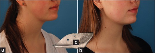
An esthetic case before (a) and after (b) bilateral jaw angle implantation. Although the implants were rather small (c), the demarcation between the face and neck by surgical definition of the mandibular angle can be well appreciated
All 12 of the patients were satisfied. In Ridwan-Ramana et al.'s series of 27 porous ethylene implants placed at the mandibular angle in 11 patients, 18.2% were dissatisfied.[16] Communication with the surgeon revealed that the actual percentage might be higher because of the retrospective nature of the study. This underscores the importance of preoperative design approval by the patient.
Ridwan-Pramana et al. reported a 27.3% infection rate when using porous polyethylene in the mandibular angle area.[16] As porous ethylene is not osseointegrating,[17] it may become infected because fibrovascular ingrowth takes 3 months.[16] The implant can also migrate when not fixed with long enough screws, which may cause it to be exposed and extruded.[18]
Aiache[2] mentioned double closure over silicone implants, and Yaremchuk[4] mentioned “a generous intraoral mucosal incision 1 cm high in the sulcus at its labial side,” to which the author now adheres.
In Whitaker’s[1] experience, autologous (calvarial bone) onlays and sandwich osteotomies yielded unpredictable results because of resorption and symmetry issues, and he discontinued their use. Triaca et al.[19] used an extended chin osteotomy using frequent bone grafts and posterior design corrections with the “chin-wing” technique. Results regarding symmetry, fracture, and infection complications are not yet available at the time of writing.
Patient-specific PEEK implants have the advantage of elasticity near to that of bone.[20] Medical-grade PEEK (Optima LT, Invibio, West Conshohocken, PA, USA) is as expensive as 3D-printed titanium alloys, but its behavior when transorally implanted is not yet known.
Declaration of patient consent
The authors certify that they have obtained all appropriate patient consent forms. In the form the patient(s) has/have given his/her/their consent for his/her/their images and other clinical information to be reported in the journal. The patients understand that their names and initials will not be published and due efforts will be made to conceal their identity, but anonymity cannot be guaranteed.
Financial support and sponsorship
Nil
Conflicts of interest
Dr. Mommaerts is innovation manager at CADskills bvba.
REFERENCES
- 1.Whitaker LA. Aesthetic augmentation of the posterior mandible. Plast Reconstr Surg. 1991;87:268–75. doi: 10.1097/00006534-199102000-00008. [DOI] [PubMed] [Google Scholar]
- 2.Aiache AE. Mandibular angle implants. Aesthetic Plast Surg. 1992;16:349–54. doi: 10.1007/BF01570699. [DOI] [PubMed] [Google Scholar]
- 3.Semergidis TG, Migliore SA, Sotereanos GC. Alloplastic augmentation of the mandibular angle. J Oral Maxillofac Surg. 1996;54:1417–23. doi: 10.1016/s0278-2391(96)90256-6. [DOI] [PubMed] [Google Scholar]
- 4.Yaremchuk MJ. Mandibular augmentation. Plast Reconstr Surg. 2000;106:697–706. doi: 10.1097/00006534-200009030-00030. [DOI] [PubMed] [Google Scholar]
- 5.Bastidas N, Zide BM. The treachery of mandibular angle augmentation. Ann Plast Surg. 2010;64:4–6. doi: 10.1097/SAP.0b013e31819b70d4. [DOI] [PubMed] [Google Scholar]
- 6.Thomas MA, Yaremchuk MJ. Masseter muscle reattachment after mandibular angle surgery. Aesthet Surg J. 2009;29:473–6. doi: 10.1016/j.asj.2009.09.006. [DOI] [PubMed] [Google Scholar]
- 7.Mommaerts MY. The ideal male jaw angle – An Internet survey. J Craniomaxillofac Surg. 2016;44:381–91. doi: 10.1016/j.jcms.2015.12.012. [DOI] [PubMed] [Google Scholar]
- 8.Büttner M, Mommaerts MY. Contemporary aesthetic management strategies for deficient jaw angles. PMFA News. 2015;2:6–9. [Google Scholar]
- 9.Mommaerts MY. Hemifacial microsomia: Management of the vertical ramus compartment. Plast Aesthet Res. 2015;2:98–106. [Google Scholar]
- 10.Mommaerts MY, Büttner M, Vercruysse H, Jr, Wauters L, Beerens M. Orbital wall reconstruction with two-piece puzzle 3D printed implants: Technical note. Craniomaxillofac Trauma Reconstr. 2016;9:55–61. doi: 10.1055/s-0035-1563392. [DOI] [PMC free article] [PubMed] [Google Scholar]
- 11.Cordey J, Borgeaud M, Perren SM. Force transfer between the plate and the bone: Relative importance of the bending stiffness of the screws friction between plate and bone. Injury. 2000;31(Suppl 3):C21–8. doi: 10.1016/s0020-1383(00)80028-5. [DOI] [PubMed] [Google Scholar]
- 12.Fukuda A, Takemoto M, Saito T, Fujibayashi S, Neo M, Pattanayak DK, et al. Osteoinduction of porous Ti implants with a channel structure fabricated by selective laser melting. Acta Biomater. 2011;7:2327–36. doi: 10.1016/j.actbio.2011.01.037. [DOI] [PubMed] [Google Scholar]
- 13.Lin CY, Kikuchi N, Hollister SJ. A novel method for biomaterial scaffold internal architecture design to match bone elastic properties with desired porosity. J Biomech. 2004;37:623–36. doi: 10.1016/j.jbiomech.2003.09.029. [DOI] [PubMed] [Google Scholar]
- 14.de Wild M, Schumacher R, Mayer K, Schkommodau E, Thoma D, Bredell M, et al. Bone regeneration by the osteoconductivity of porous titanium implants manufactured by selective laser melting: A histological and micro computed tomography study in the rabbit. Tissue Eng Part A. 2013;19:2645–54. doi: 10.1089/ten.TEA.2012.0753. [DOI] [PubMed] [Google Scholar]
- 15.Mohan K, Cox JA, Dickey RM, Gravina P, Echo A, Izaddoost SA, et al. Treatment of infected facial implants. Semin Plast Surg. 2016;30:78–82. doi: 10.1055/s-0036-1580727. [DOI] [PMC free article] [PubMed] [Google Scholar]
- 16.Ridwan-Pramana A, Wolff J, Raziei A, Ashton-James CE, Forouzanfar T. Porous polyethylene implants in facial reconstruction: Outcome and complications. J Craniomaxillofac Surg. 2015;43:1330–4. doi: 10.1016/j.jcms.2015.06.022. [DOI] [PubMed] [Google Scholar]
- 17.Maas CS, Merwin GE, Wilson J, Frey MD, Maves MD. Comparison of biomaterials for facial bone augmentation. Arch Otolaryngol Head Neck Surg. 1990;116:551–6. doi: 10.1001/archotol.1990.01870050051005. [DOI] [PubMed] [Google Scholar]
- 18.Menderes A, Baytekin C, Topcu A, Yilmaz M, Barutcu A. Craniofacial reconstruction with high-density porous polyethylene implants. J Craniofac Surg. 2004;15:719–24. doi: 10.1097/00001665-200409000-00004. [DOI] [PubMed] [Google Scholar]
- 19.Triaca A, Brusco D, Guijarro-Martínez R. Chin wing osteotomy for the correction of hyper-divergent skeletal class III deformity: Technical modification. Br J Oral Maxillofac Surg. 2015;53:775–7. doi: 10.1016/j.bjoms.2015.05.015. [DOI] [PubMed] [Google Scholar]
- 20.Kim MM, Boahene KD, Byrne PJ. Use of customized polyetheretherketone (PEEK) implants in the reconstruction of complex maxillofacial defects. Arch Facial Plast Surg. 2009;11:53–7. doi: 10.1001/archfaci.11.1.53. [DOI] [PubMed] [Google Scholar]


