

Abstract
Formation of engineering tissues (ET) remains an important scientific area of investigation for both clinical translational and mechanobiological studies. Needled-nonwoven (NNW) scaffolds represent one of the most ubiquitous biomaterials based on their well-documented capacity to sustain tissue formation and the unique property of substantial construct stiffness amplification, the latter allowing for very sensitive determination of forming tissue modulus. Yet, their use in more fundamental studies is hampered by the lack of (1) substantial understanding of the mechanics of the NNW scaffold itself under finite deformations and means to model the complex mechanical interactions between scaffold fibers, cells, and de novo tissue; and (2) rational models with reliable predictive capabilities describing their evolving mechanical properties and their response to mechanical stimulation. Our objective is to quantify the mechanical properties of the forming ET phase in constructs that utilize NNW scaffolds. We present herein a novel mathematical model to quantify their stiffness based on explicit considerations of the modulation of NNW scaffold fiber-fiber interactions and effective fiber stiffness by surrounding de novo ECM. Specifically, fibers in NNW scaffolds are effectively stiffer than if acting alone due to extensive fiber-fiber cross-over points that impart changes in fiber geometry, particularly crimp wavelength and amplitude. Fiber-fiber interactions in NNW scaffolds also play significant role in the bulk anisotropy of the material, mainly due to fiber buckling and large translational out-of-plane displacements occurring to fibers undergoing contraction. To calibrate the model parameters, we mechanically tested impregnated NNW scaffolds with polyacrylamide (PAM) gels with a wide range of moduli with values chosen to mimic the effects of surrounding tissues on the scaffold fiber network. Results indicated a high degree of model fidelity over a wide range of planar strains. Lastly, we illustrated the impact of our modeling approach quantifying the stiffness of engineered ECM after in vitro incubation and early stages of in vivo implantation obtained in a concurrent study of engineered tissue pulmonary valves in an ovine model.
Graphical Abstract
1 Introduction
Regenerative medicine has led to new therapies being used to treat a number of pathologies (mainly wound healing and orthopedics) and has potential to significantly impact medicine as whole by providing the ability to fully restore diseased and injured tissues or entire organs [1]. Such approaches require the development of engineered tissues (ET), and more recently there is growing interest in utilizing ET technologies to perform pharmacological screening [2] or to systematically investigate cellular mechanobiology and interactions between cells and extracellular matrix (ECM) [3–5]. Scaffold materials play important roles as they can mimic the native ECM environment [6], modulate cell behavior, [7] and dictate structure and function of the ET [8].Scaffold technologies that support these approaches remain an important scientific area of investigation and development.
Historically, a diverse number of different scaffold technologies have been explored and utilized in a multitude of engineered tissue (ET) applications. Decellularized native tissues offer excellent structural similarities to the goal tissue structures [9], however host body reactions and long-term functionality due to strong detergents and decellularization agents raise concerns [10, 11]. Degradable synthetic scaffolds, such as those made from polymeric materials, represent some of the earliest materials used to support the growth of ET [12]. Materials such as polyglycolic acid (PGA) and polylactic acid (PLA) are attractive due to their well-defined chemical, biological, and mechanical properties. These materials have seen frequent use as they easily degrade in vivo, can be tailored for diverse applications, and have general acceptance within the medical community.
Multi-filament needled-nonwovens (NNW) scaffolds made of bioresorbable PGA and/or PLA crimped fibers represent one the earliest and most ubiquitous biomaterials used as ET scaffolds [13]. During manufacture, fibers are crimped and a needle-array punch entangles fibers sufficiently to bind them (although there is no direct adhesion between fibers), and yields an interconnected porous structure highly suitable for scaffold-based ET approaches [14, 15]. NNW scaffolds are sufficiently strong and mechanically stable, although fiber slippage results in limited elastic recovery under tensile loading [16, 17]. They continue to serve an important role in ET formation, both as a benchmark for evaluating novel biomaterials and for their unique capacity to promote tissue formation, the latter arising from their intricate microstructure and micromechanics. They are attractive in that the bulk stiffness of the scaffold-tissue construct is exquisitely sensitive to changes in the forming ECM modulus. This is particularly useful when studying the early stages of tissue formation where the magnitude of the ECM moduli are typical rather small (< 10 kPa).
From a biomechanics perspective, a fundamental issue is the lack of information concerning the mechanics of the NNW scaffold itself and the complex mechanical interactions between nonwoven scaffolds, cells, and especially the de novo forming ECM. Thus, while NNW scaffolds have yielded promising results in diverse ET applications such as heart valves [18, 19], bladder [20], blood vessels [21], and cartilage [22], their use in more fundamental studies is hampered by the lack of: (1) substantial understanding of the complex interactions in between degrading scaffold and forming de novo tissues; and (2) rational models with reliable predictive capabilities describing the evolving mechanical properties of cell-seeded ET constructs based on NNW scaffolds and their response to mechanical stimulation. Engineered tissue approaches not only are well positioned for the study of cellular mechanobiology as they serve as controllable and reproducible testbed for hypothesis formulation and verification, but also present themselves as highly appealing alternative to synthetic implants once and if the functional requirements of clinical application are met. Indeed, both aspects of the ET approach are in fact needed and work synergistically together.
Engelmayr and Sacks proposed the first microstructural model to describe and predict the mechanical response of NNW scaffolds in their virgin state [13]. The model consisted of an extension to the model originally proposed by Freeston and Platt [23] to account for undulated fibers that bend (as opposed to straight fibers that extend) and for the co-existence of fiber-fiber needling points that physically bond fibers and fiber-fiber entanglements. Fiber-fiber cross-over points are responsible for changing the effective fiber crimp (and not the intrinsic crimp imparted to fibers during fabrication), specifically in effective crimp amplitude, wavelength, and consequently, their mechanical response [24]. In another study with cell-seeded NNW scaffolds incubated under cyclic flexure, Engelmayr et al. observed a strong positive linear relation between construct effective stiffness and engineered ECM deposition [25]. The traditional rule-of-mixtures was not able to describe the effective stiffness of the scaffold-ECM composite (substantially underestimated the experimentally measured stiffness), and demonstrated that additional reinforcement mechanisms must be acting within the scaffold-ECM composite. The authors proposed that the principal reinforcement mechanism acting in scaffold-ECM composited is an increase in the number of rigidly-bound fiber-fiber cross-over points, with a concomitant decrease in effective arc length and amplitude of the curved segments spanning in between these points, and thus resulting in effectively stiffer fibers. Their study demonstrated that the extension of curved fiber segments in between fiber-fiber cross-over points is a fundamental mechanism occurring during the deformation of NNW scaffolds, and most importantly, the impact of surrounding ECM in the modulation of the effective scaffold stiffness. However, their study was limited to flexure as the only mode of deformation and strains achieved were of the order of magnitude < ~5%. More robust models are necessary to understand and frame the complex mechanical behavior of NNW scaffolds, and richer deformations regimes are needed to motivate and drive their development, specifically the behavior of NNW scaffolds and ET constructs based on those under multi-axial strain.
Our group has been interested in developing an improved fundamental understanding of the underpinnings of ET growth and development through highly-integrative approaches bridging modeling- simulation-experimentation to address critical barriers in the field of tissue engineering and its over-reliance on pure empiricism [26, 27]. For example, we have developed a modeling framework for engineered tissue formation in NNW scaffolds under mechanical stimulation. Mechanical training is widely recognized as one of the most relevant methods to enhance ET accretion and microstructure, leading to improved mechanical behavior and function; however, the understanding of the underlying mechanisms remains rather limited. In order to explain such augmentation of production and stiffness observed by Engelmayr et al. [25] in dynamically flexed NNW scaffolds, we have hypothesized that mechanical deformation of the porous scaffolds introduces a pumping mechanism that relieves diffusional constraints and supplies more nutrients to cells and consequently enhance their synthetic behavior [26]. However, the improved biochemical environment was not sufficient to explain the substantial improvement observed in another scaffold system (electrospun PEUU [27]) that is able to undergo large deformations (up to 50% stretch), thus reinforcing the role of mechanical deformation in the direct stimulation of the synthetic behavior of cells [27]. An improved understanding of the process of mechanical stimuli transfer, i.e. from the scaffold to the cells, in these mechano-sensitive cell-scaffold systems will lead to more rational design and manufacturing of ETs operating under highly demanding mechanical environments.
In the present study, we extend our previous flexure-based studies on NNW scaffolds to develop a robust mathematical model to predict the mechanical response of the forming ECM by the stiffness amplification of NNW scaffolds under more generalized planar loading states. We illustrate the impact of our modeling approach by employing it to quantify the stiffness of engineered ECM after in vitro incubation and early stages of in vivo implantation obtained in a concurrent study of engineered tissue pulmonary valves in an ovine model [28, 29].
2 Materials and Methods
An integrative approach involving a systematic experimental program coupled to novel theoretical development was developed. We begin with a single-fiber, and proceed through step-by-step homogenization to account for the complete scaffold-ECM construct. To calibrate our model, we utilized polyacrylamide (PAM) gel of variable known stiffness to mimic the effects of surrounding tissues on the scaffold fiber network. With such, our modeling approach allows the determination of the current stiffness of ECM existing at any time point of in vitro incubation or post-implantation in vivo function.
2.1 Single fiber elastica model
Scaffold fibers are modeled as sinusoids that undergo conformational changes upon deformation. To formulate an analytical model of the mechanical response of a single fiber suitable for integration into a broader framework for nonwoven scaffolds, a variation of the approach proposed by Garikipati et al. [30] was employed; however, this approach is restricted to tensile behavior and to planar deformations. We start with a single fiber, represented with a sinusoidal geometry and parametrized using amplitude a, period L0, and diameter d, the latter being factored only into the fiber mechanical properties, i.e. bending and extensional moduli. In a Cartesian coordinate system, the loci of a fiber laying in the (x,y)-plane with respect to Lagrangian coordinate t is
| (1) |
The total strain energy of a single fiber is split into bending and extensional components and given by
| (2) |
where B = EI / (2A) and EA are the bending and extensional effective stiffness respectively. The material is characterized by its Young’s modulus E, and A and I are the cross-sectional areas and 2nd moment of inertia of the circular fiber. The current configuration of the fiber is fully characterized by fiber stretch λ and curvature κ, computed with derivatives of y and Y with respect to x and X respectively, i.e.
| (3) |
The reference configuration is characterized by reference amplitude a0 and period L0 to yield reference stretch λ0 = 1 and reference curvature κ0. It is useful to consider end-to-end displacement g (Figure 1e) where L = L0 + g with current amplitude a to be determined as a function of end-to-end displacement g. The goal is to find the appropriate relationship of current amplitude a(g) with the force f, i.e.
Figure 1.

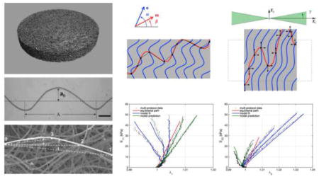
(a) micro-CT image of the 50:50 PGA:PLLA needled-non-woven scaffold material; (b) pore size distribution; (c) orientation index obtained by small angle light scattering on a square specimen of virgin NNW scaffold; (d) fiber orientation distribution obtained from SALS measurements; (e) uncoiling of a sinusoidal elastica; (f) representative micrograph of a crimped PGA fiber teased from a 50:50 PGA:PLLA nonwoven scaffold (40X original magnification), scale bar = 100 μm); (g) SEM image depicting the planar microstructure of the nonwoven scaffold and showing effective crimp wavelength and amplitudes with different fiber-fiber cross-over points (Figures 1f and 1g were adapted with permission from Engelmayr and Sacks [57])
| (4) |
The amplitude is then determined through a minimization procedure consisting on finding the amplitude that results in the minimal stored energy in an equilibrium configuration, i.e.
| (5) |
The fiber being in equilibrium indicates that ∂ψ/∂a = 0 and the remaining partial derivatives in Equation (4) are
| (6) |
Lastly, the force-displacement relationships given as the integral in terms of the material coordinate t ∈ [0,L0] is
| (7) |
where
| (8) |
and t̃ is the Eulerian counterpart of Lagrangian coordinate t given by t̃ = (L/L0)t.
In the current case of deforming sinusoidal arcs, the stretch and curvature are not homogeneous along fiber length. Non-homogeneous stretches and curvatures pose problems with the analytical treatment of the sinusoidal elastica (as opposed to elasticas based on circular arcs as presented in [30, 31]). However, while the fiber is uncrimping, only bending contributes substantially to the elastic energy stored since the extensional stiffness is often 3 orders of magnitude greater than the bending stiffness (due to L ≫ d). Thus, the extensional stretch is negligible (still non-homogeneous, but small everywhere) during this regime. In order to enforce homogeneous extensional stretch in the deforming sinusoid, we employ an alternative parametrization of the fiber with the inverse mapping
| (9) |
where S ∈ [0,L] is a Lagrangian coordinate along fiber length. A homogeneous stretch is imposed through s = λS and the forward mapping t̃ is obtained as t̃ = t̃(s). Although the inverse mapping is straightforward as given by an arc-length integral, the forward mapping involves solving an incomplete elliptical integral of the second kind. Enforcing homogeneous stretch correctly is paramount for the assumption of minimal stored energy to determine the correct equilibrium configuration (Equation (5)) – fiber straightening induces local (pointwise) compression and extension, which increase stored elastic energy and interfere with the macroscopic behavior of the sinusoidal elastica. The Pf − λf relationships of individual PLLA and PGA fibers were obtained using Equation (7) with fiber dimensions from previous study of Engelmayr and Sacks [13] and representative moduli in the small strain regime were obtained by fitting the uniaxial response with Pf = ηelastica(λf − 1) with 1 < λ <1.05.
2.2 Single fiber finite element model
The elastica model described above is very appropriate for the exploration of the influence of fiber geometry in its mechanical response, specifically to parametrically studying the effects of fiber amplitude and fiber undulation wavelength. However, the analytical treatment of the elastica framework introduces several underlying assumptions, such as fibers remain in a co-planar sinusoidal configuration throughout their deformation. Whereas these assumptions remain valid for undulated fibers being extended, they are not suitable to handle cases where fibers are compressed. Herein, we employ the finite element (FE) method as complement to the analytical study with the elastica framework for the exploration of more complex situations where other mechanisms not captured within the elastica framework come into play. Examples of such are: (1) the substantial geometric deviations of compressing fibers from a sinusoidal configuration as they deform into configurations with larger radii of curvature with smoother kinks (as opposed to a compressing sinusoidal wave that would result in very sharp kinks), and (2) out-of-plane motions that occur after the onset of any slight instability and will promote buckling and remarkable different force vs. displacement responses. Additionally, the FE method was used for validation of the elastica model.
In the current study, we simulated a neo-Hookean sinusoidal fiber under tension and compression, with the fiber not being restricted to deform into co-planar sinusoidal configurations only. Force vs. displacement relationships were determined with the following FE specifications utilized:
An implicit analysis was chosen in order to ensure unconditional stability of the quasi-static solution at the expense of computational efficiency, which in this case was not severe.
37,152 quadratic tetrahedral elements with reduced integration were employed to model the nearly incompressible hyperelastic material of the fiber.
Nearly incompressible neo-Hookean hyperelastic material model with shear modulus characterizing PLLA fiber was employed. Nearly incompressilbity was achieved with a standard penalty-formulation and choosing bulk modulus K ≫ μ.
Fiber dimensions were taken from a previous study [13] and are dPLLA = 16.36 μm, dPGA = 12.95 μm, 0.5 L0= 1.774 mm, and a0= 0.195 mm. Shear modulus of PLLA and PGA in Equation (7) were obtained as 1/3 of Young’s modulus of EPLLA = 10.42 GPa and EPGA = 18.78 GPa respectively.
The boundary conditions were set as follows: the fiber was pinned at the central node of its left tip (zero displacement, but free rotations) and a concentrated force (tensile and compressible) on the direction of the x-axis was applied on the central node of its right tip.
Two types of simulations were conducted, the first type with the fiber constrained to in-plane motion only, whereas the second type with the fiber free to move out-of-the-plane and buckle upon compression.
2.3 Nonwoven scaffold/ECM meso-structural model
To model the macroscopic scaffold-construct mechanical behavior, we start defining the hyperelastic strain energy density Ψ of a representative volume element, which is assumed to be small enough so that the deformation gradient tensor F is homogenous, yet large enough to allow local averaging of the fiber ensemble and constituents meso-structure. Previous studies have found this RVE to be a 1 mm3 cube [13]. We further assumed the mechanical contributions of the fiber network and the forming de novo ECM are weighted by their respective volume fractions ϕf and ϕm respectively
| (10) |
where C = FFT is the left Cauchy-Green stretch tensor. We assume that all non-fibrous volume is filled with forming ECM tissue, i.e. ϕf + ϕm = 1, and the present model is restricted to situations where complete tissue formation has occurred. In our previous experiments with NNW scaffolds incubated in vitro, we have observed that the de novo tissues fill the void space of the NNW approximately after 1 week [25]. For the present study (cf. Section 2.6), NNW scaffolds incubated in vitro for 1 month demonstrated similar tissue formation [28, 29].
The macro-level response in terms of the 2nd Piola-Kirchhoff stress tensor S is derived using
| (11) |
where E = (C − I)/2 is the Green-Lagrange strain tensor and I is the identity tensor, along with Lagrange multiplier p to enforce material incompressibility (at the ET construct level). Equations (10) and (11) represent a biphasic composite (NNW scaffold-de novo ECM) characterized by the summation of the mechanical responses of each component, which are delineated in the following sub-sections.
2.3.1 Constitutive model of forming ECM
To model forming ECM surrounding the scaffold fibers, we utilize a single isotropic hyperelastic neo-Hookean material model with strain energy density function
| (12) |
The neo-Hookean material model is chosen for two reasons: (1) the neo-Hookean model is the asymptotic approximation of any nonlinear material under small deformations; and (2) the neo-Hookean model is appropriate to describe the mechanical response of PAM gel. The objective of the present study is the quantification of the stiffness of the de novo ECM formed in a NNW scaffold. In order to obtain values for its stiffness, we have developed a methodology that infers ECM stiffness from biaxial testing data on scaffold-ECM composites and is calibrated with systematic testing on scaffold-PAM gel scaffolds. Certainly ECM shows complex mechanical responses when subjected to large deformations, e.g. highly nonlinear and anisotropic. However, these regimes require more complicated constitutive formulations and experimental programs for their characterization, and are not achievable experimentally when the ECM is present at early stages of incubation as one of the components of a NNW scaffold-de novo ECM engineered tissue composite. Assuming a state of plane stress, i.e. S13= S23= S33= 0, the Lagrange multiplier p can be determined and the resulting contribution of the surrounding de novo ECM towards the 2nd Piola-Kirchhoff stress is
| (13) |
The state of plane stress is appropriate for the kinematical description of planar biaxial testing of thin samples as normal and shear stress in the transversal direction are negligible [32]. At the same time, incompressibility is trivially obtained with the determination of F33.
2.3.2 Nonwoven scaffold fiber material model
Scaffold fibers undergo a uniaxial strain Ef = n·En that is imposed from the construct-level Green’s strain tensor E in an affine manner, with the mean fiber direction being given by n(θ) = cos(θ)e1+ sin(θ)e2 with θ being measured from the x-axis. The normalized fiber orientation distribution Γ(θ), θ ∈ [− π/2, π/2] was obtained from SALS data in our previous study [13]. Initially, assumed that within the strain range under consideration, the scaffold fibers could be modeled using a typical Pf vs. λf response with strain energy given by ψf (λf) = 0.5ηf (λf − 1)2 for all fiber stretch λf ∈ [0,∞], i.e. under tension and compression, and ηf is the individual fiber stiffness. The effective stiffness of the fibers in the NNW could be represented as the average of the stiffness of PGA and PLLA fibers (the nonwoven scaffold is a 50:50 blend) computed from the elastica analysis of each individual class of fibers. However, numerous intersections with other fibers will reduce the effective length and amplitude of fibers (Figure 1g), and increase their effective stiffness by a fiber-fiber interaction amplification factor χ. Thus, the effective stiffness of a fiber in a NNW scaffold is higher than its stiffness if acting alone and given by
| (14) |
Exploration of the behavior of individual fibers with the elastica analysis and the FE simulations led to the conclusion that scaffold fibers were unable to bear loads that involve the substantial reduction of their length, or alternatively, no elastic energy is stored in the material by reducing the effective fiber length. This assumption was supported by our experimental data (cf. Results and Discussion and Figure 9 for further details). Although the above elastica framework indicated that fibers would respond elastically when compressed and have the same effective moduli in tension and compression, out-of-plane deformations will occur as observed in the pilot FE simulations (cf. Figure 5). Due to this large-amplitude out-of-plane motion, the apparent stiffness of the fiber under compression becomes negligible. Thus, we modeled the uniaxial response of individual scaffold fibers as having: (1) the extensional stiffness obtained by the elastica framework and corroborated by the FE simulations under tension, but (2) without any stiffness under compression. This lead to the following effective fiber model for Ψf
Figure 9.

2nd Piola stress vs. stretch in a representative sample with PAM gel with stiffness μm = 3.8 kPa for two different stress-controlled protocols (37.5:50, and 50:37.5 respectively, experimental data in black dots). The first and second protocols result in shrinkage in the X1 direction. A model that considers NNW scaffold fibers to support compressive stresses (red lines) is not able to predict correctly the positive stresses that occur in the shrinking direction, yet works fine when stretches are positive. A model that considers that fibers buckle and are unable to carry compressive loads (blue lines) is able to predict the deformations observed in NNW scaffolds in all regimes of deformations.
Figure 5.
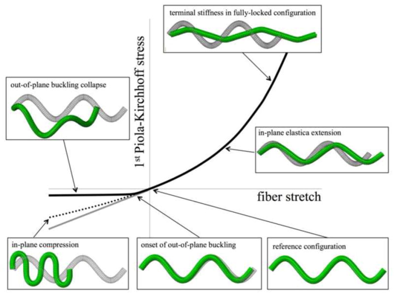
General behavior of an undulated fiber under tension and compression obtained with the FE method. The FE model was composed by 37,152 quadratic tetrahedral elements, fiber dimensions and properties were taken from a previous study (cf. [58]) and nearly incompressibility was achieved with K ≫ μ. The central nodes of the faces of the fiber tips (left and right) were employed to enforce boundary conditions – pinned and a concentrated forces respectively. Under tension, the elastica solution is able to capture the behavior of the fiber as it uncoils and reaches the fully locked configuration (solid line on the right, top box). However, out-of-plane motions develop at very early stages of fiber compression and deviate its behavior into remarkably different configurations that involve substantial out-of-plane translational movements of segments of the fiber and is associated with a compressive stiffness that is negligible in comparison with the tensile stiffness (solid line on the left). If the out-of-plane motion restricted the elastica solution under compression is obtained up until a point where the assumption that the fiber remains in a sinusoidal configuration breaks down (bottom left box) and its stiffness starts to deviate from the elastica-predicted infinitesimal modulus under compression (dotted line and gray line respectively).
| (15) |
which results in the following effective Pf − λf relationship
| (16) |
Note that this arises mainly due to fiber buckling/crimping mechanisms upon compression and is identical to the commonly employed effective collagen fiber models [33–36].
The resulting 2nd Piola-Kirchhoff stress tensor in an individual fiber is obtained as
| (17) |
Where fiber stretch λf is related to the deformation gradient through . Lastly, when taken collectively, the resulting 2nd Piola-Kirchhoff stress tensor in the fiber phase of the material is obtained through integration of the individual fiber responses over the oriented fiber-ensemble, i.e.
| (18) |
Fibers compounding the RVE of the NNW scaffold are modeled with an orientation distribution Γ (θ) that is measured experimentally (cf. Figure 1) and baseline stiffness that is obtained from the analysis of the behavior of the single fibers (cf. Equation (14)). When present in NNW scaffolds effective fiber stiffness is modulated with a fiber amplification factor χ to account for changes in effective crimp amplitude and wavelength that occurs with the introduction of fiber-fiber cross-over points with needling and weaving.
2.3.3 Model of additional fiber-fiber interactions in nonwoven scaffolds
Fiber-fiber interactions arise due to the diverse range of orientation of fibers in the nonwoven scaffolds in conjunction with the inability for fibers to support compression and the extensive frictional bonding that exist in non-woven scaffolds [13, 24]. Specifically, we hypothesize the following micro-mechanisms for fiber-fiber interactions (Figure 2): (1) when the material undergoes substantial extension in one direction and shrinkage in the other, fibers aligned with the shrinkage of compression will undergo large-translational motions and will not store significant amounts of elastic energy, and furthermore, (2) these translational effects of collapsing fibers and their crosslinks with fibers aligned in the extensional direction will indeed contribute towards the extension in the other direction.
Figure 2.
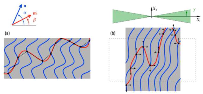
Schematic of fiber-fiber interactions in a NNW scaffold. Multiple fiber-fiber cross-over points are introduced by needling (black dots), which are responsible for substantially decreasing the effective crimp amplitude and wavelength of fiber segments, and consequently, increase the effective stiffness of a fiber, i.e. the red fiber is effectively much stiffer when part of a NNW scaffold n comparison to if acting alone. Moreover, extensive anisotropic interactions occur when stretching and shrinkage simultaneously. Fibers oriented within [− γ, γ] with the direction of shrinkage are unable to carry compressive stresses their segments become highly non-aligned (shown in green). Additionally, out-of-axis translational movement, which occur even with the individual fiber (shown in red in (a)), is able to contribute further to the extensional direction (arrows in (b)).
This effect must be accounted with an additional fiber-fiber interaction term. Interactions in between fiber-ensembles in microstructural models were first proposed by Sacks et al. [37] for cross-linked collagenous tissues and also adapted to myofiber-collagen fiber mechanical coupling in the mechanical response of passive myocardium [38]. Here we adapt a similar formulation but consider interaction effects strictly at the individual fiber level. As opposed as in dense collagenous tissues, the micro-structure of NNW scaffolds is not based on fiber-ensembles of aligned fibers with common orientation that interact with other ensembles, instead NNW are composed of fibers with a diverse range of orientation connected by a vast number of fiber-fiber cross-over points.
We first consider two fibers with orientations n(α) and m(β) in the reference configuration, with α and β being the angles between fiber orientation and the x-axis (Figure 2). These two fibers can interact mechanically by elongation and relative rotation, and both effects can be accounted using pseudo-invariant I8= n ·Cm [39, 40]. Given a deformation gradient F, the associated fiber stretches are
| (19) |
To account for all possible fiber-fiber interactions, weighted by the fiber orientation distribution, we use the following form for the total inter-fiber interactions
| (20) |
We restrict to interactions due to relative stretches between fibers, i.e.
| (21) |
To obtain the contribution towards the stress arising due to the fiber-fiber interactions, we employ
| (22) |
to obtain
| (23) |
2.3.4 Complete mathematical model form
The final expression for the total 2nd Piola-Kirchhoff stress for the nonwoven-ECM composite is obtained by combining Equations (13), (18) and (23), given by
| (24) |
To properly describe the observed experimental data, we include the assumption that the effective stiffness of scaffold fibers and the magnitude of fiber-fiber interactions, and ηint respectively to have their effects modulated as functions of the stiffness the surrounding ECM, i.e.
| (25) |
2.4 Model validation and experimental calibration
2.4.1 NNW scaffold assembly
Sheets of nonwoven scaffolds containing 50% fibers of polyglycolic acid and 50% fibers of poly-L-lactic acid (Concordia Medial, Warwick, RI) were assembled by machine-needled punching as previously described [28, 29]. Tissue analogs with tunable mechanical properties within the range of native tissue were assembled with polyacrylamide gel as previously described [24]. The modulus of the PAM gel is modulated with the concentration of acrylamide/bis prior to polymerization. Previous studies showed ECM-like stiffness with ranges of elastic moduli from 30 to 800 kPa [41], and that it could readily permeate the nonwoven scaffold.
For each experiment, 10 ml of PAM gel of a particular concentration of acrylamide/bis solution was prepared per manufacturer’s guidelines (Bio-Rad Laboratories, Hercules, CA). Deionized water and 30% solution of 37:5 acrylamide/bis and deionized water were combined in the appropriate ratio (Table 1) with 2500 μl of 1.5M Tris/HCl buffer (Bio-Rad Laboratories, Hercules, CA), 100μl of 10% sodium dodecyl sulfate (SDS) (Bio-Rad Laboratories, Hercules, CA), 50μl of 10% (w/v) ammonium persulfate (APS) (SIGMA, Sigma-Aldrich Co., St. Louis, MO), and 5μl of tetramethylethylenediamine (TEMED) (Bio-Rad Laboratories, Hercules, CA). The APS solution was made fresh for each experiment by adding 0.5g of APS to 5ml of water.
Table 1.
Volume measurements for acrylamide/bis (acryl/bis) and deionized water (DI H2O) to obtain specific PAM gel monomer concentrations. All values reported are for 10 ml total volume.
| monomer concentration | acryl/bis (μl) | DI H2O (μl) | shear modulus (kPa) | SEM (kPa) |
|---|---|---|---|---|
| 5.00% | 1670 | 5680 | 4.286 | 0.794 |
| 7.50% | 2500 | 4850 | 7.777 | 0.635 |
| 10.00% | 3335 | 4015 | 12.540 | 0.613 |
| 11.25% | 3760 | 3590 | 19.524 | 0.594 |
| 12.50% | 4170 | 3180 | 24.920 | 0.824 |
| 17.50% | 5830 | 1520 | 42.381 | 0.476 |
| 19.10% | 6365 | 985 | 47.778 | 0.655 |
| 20.70% | 6900 | 450 | 51.270 | 1.111 |
| 22.00% | 7350 | 0 | 56.508 | 0.952 |
A Bio-Rad gel-casting module was assembled using 1mm spacer plates, and approximately 2.5 ml of the acrylamide/bis solution was pipetted in between the plates. Subsequently, PGA:PLLA copolymer scaffold were cut to 15x15 mm squares specimens (n = 5 per concentration), immersed into the acrylamide/bis solution until saturated (<30s), and then slipped between the spacer plates using forceps such that they became immersed in the 2.5 ml of acrylamide/bis solution already between the plates. After the scaffold specimens were situated between the spacer plates, the remaining volume of acrylamide/bis solution was pipetted on top of the scaffolds such that the scaffolds were entirely immersed. Finally, ~100–200 μ of 1-butanol (SIGMA) saturated with water (e.g., 1 ml of water mixed with 4.5 ml of 1-butanol) was pipetted on top of the acrylamide/bis solution to aid in acrylamide/bis polymerization, as it is inhibited by oxygen. Acrylamide/bis solutions were allowed to gel for 1 h at room temperature prior to removal from the spacer plates. After the plates were removed, scaffold–PAM gel composites were cut from the gel sheet, stored in cold deionized water, and then prepared for biaxial tensile testing.
2.4.2 NNW scaffold microstructural analysis
Previous studies on this PGA:PLLA nonwoven scaffold system were performed using extended-volume scanning laser confocal microscopy [29], Briefly, conventional scanning laser confocal microscopy was used to obtain high-resolution 2D plane images with small steps through the z-direction, and scaffold fiber end-to-end distance, true fiber length, fiber tortuosity, fiber volume fraction, fiber diameter, and minimum fiber-fiber distances were computed. Previous studies on this nonwoven scaffold system (Figure 1a, b) reported a volume fraction of scaffold fibers of ϕf = 0.07. Digital analysis of 3D and planar micro-CT images of pre-seeded scaffolds allowed the determination of porosity and distribution of pore size – pore size mode was 0.126 mm with 2.85% of total pore volume, whereas median and mean were 0.204 mm and 0.378 mm respectively.
Previous studies employed small angle light scattering (SALS) analysis to determine scaffold fiber orientation distribution (Figure 1c, d) [13, 24, 42]. The details of the SALS device have been described previously, including its application with fibrous polymer scaffold materials [35, 43]. To describe the representative fiber orientation distribution of the nonwoven scaffolds, a Cauchy distribution Γ(θ)
| (26) |
was used with individual distributions were aligned at median orientation μ = 0° scale factor σ = 29.2° and random orientation baseline of γ = 0.4.
2.4.3 NNW scaffold mechanical characterization
Mechanical characterization of NNW scaffold-PAM gel tissue-analogs was performed on square samples of tissue-analogs of varying PAM gel monomer concentrations (Table 1) following previously published methods for biaxial mechanical testing [32, 44]. Additionally, the virgin scaffold was tested as control group. Thickness measurements were taken using a micrometer at six locations and averaged. Stainless steel 0.016 in diameter hooks tied to both ends of 10 cm long silk suture line were attached to specimens with four hooks per side forming two loops of suture. A total of sixteen hooks were placed creating four pairs of sutures. Four small cut portions of polyproline suture were attached to the middle region of the specimen in a square pattern using cyanoacrylate glue to serve as fiducial markers for strain tracking. The specimen was then placed in the biaxial testing device chamber filled with deionized water, and the silk suture loops were attached to stainless steel dowels on actuator arms. Testing was performed at room temperature, in deionized water, under stress control, and starting from a preload of 0.2 g. Standard methods were used to determine the in-plane Green strain and Cauchy and first Piola-Kirchhoff stress tensors assuming incompressibility [44]. In all analysis, the run-time free-float configuration was used as the reference state [45].
Load-controlled biaxial mechanical testing was conducted (with n = 5) to generate data for determination of model parameters with the preferred direction of the tissue-analog was aligned with the device X1-axis. Free-floating (no-load) and tare reference states were taken before preconditioning, after preconditioning, and after full protocol testing. Ten cycles of preconditioning was found that was adequate to ensure consistent loading results from subsequent tests (equibiaxial stress up to 50 kPa). A seven protocol testing regime was used with peak X1:X2 stress ratios of 15:50, 25:50, 37.5:50, 50:50, 50:37.5, 50:25, and 50:15 kPa. Tests were performed for ten cycles with a 15 s half cycle time to quantify the quasi-static response. The experimental methods follow previously published protocols [32, 44, 45].
Equibiaxial strain responses are important for parameter estimation because stretch in any direction of the sample is similar [35, 46]. However, biaxial testing is performed under stress-controlled conditions and the equibiaxial strain path was interpolated from the experimentally acquired multiprotocol data using surface fits to the 2nd Piola Kirchhoff stress surfaces with smoothness regularization enforced in the Sobolev-norm [47, 48].
Uniaxial and pure shear experiments were performed to determine the shear modulus of PAM gels with varying monomer concentrations. Specimens of 4.5 x 10 mm for uniaxial extension and specimens of 20 x 2 mm for pure shear were cut from adjacent locations in 15 x 15 cm PAM gel sheets (n = 5 for each experimental mode). Thickness measurements were taken at six points on each specimen and averaged. Specimens were loaded between sandpaper-coated grips on a MTS Triton 2500 testing device (MTS Systems, Eden Prairie, MN). A small preload of 0.5 N was applied, the gage length recorded, and testing was performed up to 30% strain. Paired data sets (uniaxial extension and pure shear) were fit simultaneously to compute shear modulus μm in Equation (12) using the neo-Hookean model.
2.5 Parameter estimation
In principle, Equation (24) can be implemented within a robust parameter estimation procedure with the multi-protocol biaxial testing data, a multi-step parameter estimation is clearly in order given its complexity and number of parameters to be estimated. We first consider that stiffness of PLLA and PGA fibers in the small strain regime are estimated from the analysis of their elastica deformation under tension, i.e. and are determined from the slope of the Pf − λf relationship in the infinitesimal regime. We have reduced experimental data obtained by biaxial testing of NNW scaffolds (with μm = 0) and NNW scaffolds impregnated with PAM gels (with known μm) into our modeling framework through the following steps:
The stress vs. stretch paths determined experimentally with each stress-controlled protocol, specifically S11 vs. λ1 and S22 vs. λ2 are fit to surfaces spanning the entire stretch envelope that characterizes the stretch space of the sample.
The equibiaxial stretch path is determined from this surface.
The equibiaxial stretch path was used to determine parameter χ characterizing the effective fiber stiffness as the interaction term in Equation (24) vanishes (trivially as λα = λβ) and the only remaining parameter to be found is χ (μm) for each known μm.
Then, experimental data from the three central protocols (37.5:50, 50:50, and 50:37.5) was fit simultaneously to determine the interaction term ηint (μm) for each known μm and χ (μm).
Lastly, experimental data from the remaining protocols was employed to determine and validate the reliability of our model and the determined parameters to describe the behavior of the material on a per sample-basis.
2.6 Example application
The final goal of this study was to develop a robust methodology to quantify the mechanical properties of the de novo ECM component in ET constructs after in vitro incubation and early stages of in vivo implantation. The ability to quantify the stiffness of ECM during the course of in vitro incubation and in vivo function is a necessity to develop models that describe the growth and remodeling processes in ETs. However, we stress that our objective in this study is to develop an approach to infer the stiffness of ECM at specific time points rather than provide a framework to describe their evolution. We illustrate the impact of our modeling approach by applying it to ETs obtained in a concurrent study of our group on ET pulmonary valves in an ovine model [28, 29]. Cell isolation, culturing, and seeding, scaffold preparation, in vitro incubation, fabrication into pulmonary heart valve conduits, and implantation in the right ventricle outflow tract of sheep have been described in detail [28, 29]. Two non-implanted (t = 0 day) specimens were analyzed as initial post-incubation condition and the valve and conduit assemblies were explanted and analyzed at two experiment post-implantation endpoints (t = 1 day and 7 days). All specimens were supplied by the Mayer Laboratory at Children’s Hospital Boston, shipped frozen in PBS, and stored in a −80 °C freezer until tested. Based on sectioning into strips, a total of 23 specimens were analyzed at three time-points: (1) post-incubation (at t = 0, n = 4), (2) explanted after 1 day (n = 11); and (3) after 7 days (n = 8).
Histology was performed to evaluate the overall structure of the conduits with H&E to reveal non-specific ECM, cell nuclei, and scaffold. The scaffold and tissue components were segmented out and masked digitally, and pixel area was computed for tissue and scaffold components across uniform cross-sections and component volume fractions determined. Biaxial tensile mechanical testing was performed on segments of the conduit following previously described methodology (same stress-controlled protocols, but immersed in PBS). Tissue specimens were cut to provide maximum size, often rectangular in shape ranging from 5–7 mm per side. Thickness measurements were taken using a micrometer at six locations of the specimens and averaged. The circumferential direction was aligned with the X1-axis to maintain consistency between tests. Scaffold volume fraction post-incubation was computed from transmural H&E stained sections. Finally, fitting post-incubation experimental data from the biaxial testing protocols with fiber stiffness amplification χ (μm) and fiber-fiber interactions ηint (μm) that were previously calibrated with the experimental data collected with NNW scaffolds impregnated with PAM gel of known stiffness (cf. Equation (25)) allowed the estimation of the stiffness of the engineered ECM (μm).
2.7 Statistical Methods
Results are presented as mean ± standard error of the mean (SEM) for specific sample sizes listed as n. Regression analysis for the determination of the moduli of the elastica and for the fiber stiffness amplification and fiber-fiber interaction functions employed coefficient of determinations R2 computed using standard methods in MATLAB (Mathworks, Natwick, MA, USA). Statistical analysis on the estimation of the stiffness of engineered ECM was performed using Sigma plot (Systat Software, Chicago, IL, USA). Student T-test was utilized for comparison of two groups and differences were considered to be statistically significant at p < 0.05.
3 Results
3.1 Single fiber response
The common nonlinear stress vs. stretch behavior of an undulated fiber was observed under tensile extension (Figure 3 and representative moduli of the Pf − λf relationship of individual PLLA and PGA fibers in the small strain regime are listed in Table 2). Subsequently, the effective fiber stiffness in the PGA:PLLA nonwoven scaffold was determined as their average accordingly to Equation (14). Beyond a stretch λs, the slack stretch, the fibers are fully extended and their Pf − λf relationship reaches another linear regime (Figure 3). This regime is dictated by the composing material moduli and the final slope of each response, ηfinal, was obtained as a linear fit to the region λ > 1.12 and matches the prescribed material moduli accordingly to and , where slack stretch was estimated as λs = 1.11.
Figure 3.
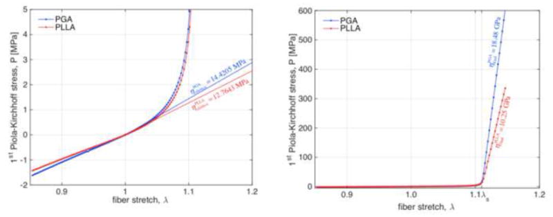
Individual fiber response obtained with the elastica framework. A smooth transition in between infinitesimal modulus and terminal stiffness occurs as the undulated fiber uncoils at around λs ≈ 1.11 (left) and reaches fully-extended configuration and approaches its terminal stiffness much larger than infinitesimal stiffness (1,000 x) and equal to the extensional modulus of the material (right). Due to its inherent assumptions, the elastica framework yields the same infinitesimal modulus in compression (left).
Table 2.
Elastica modulus and terminal stiffness obtained with Equation (7). The elastica modulus relates stress vs. strain at infinitesimal extensions as the sinusoidal elastica deforms and straightens, terminal stiffness corresponds to the uniaxial extensional modulus of the composing material.
| elastica modulus (MPa) | R2 | terminal stiffness (GPa) | R2 | |
|---|---|---|---|---|
| PGA | 14.4205 ± 0.0248 | 0.9862 | 18.483 ± 0.0269 | 1.0 |
| PLLA | 12.7643 ± 0.0219 | 0.9862 | 10.249 ± 0.0372 | 1.0 |
The tensile Pf − λf relationships of individual fibers obtained using Equation (7) were validated with FE simulations of a neo-Hookean fiber using ABAQUS with the appropriate dimensions and mechanical properties of the PGA fibers in the non-woven scaffold (Figure 4). Very good agreement was observed under tension and the elastica framework was validated by the FE analysis in the tensile regime; however, substantial deviations occurred in the compressive regime. The elastica framework results in a linear stress vs. stretch relationship in compression, whereas the finite element simulations of the corresponding sinusoidal fiber demonstrate the important role of configurational non-linearity, which are not taken into account with the elastica framework, as the geometry of the deformed fiber deviates substantially from a sinusoidal upon compression. Most importantly, when the fiber was left unconstrained to move freely out-of-plane, buckling occurred and fiber stiffness after the onset of the instability was substantially diminished (Figure 4b, green line). Preliminary parametric studies on the FE model showed that the onset of buckling, i.e. the substantial configurational change of the sinusoidal fiber such that it starts to engage in out-of-plane buckling/bending, was rather unstable and that the compressive stretch at which it happens was very sensitive to loading conditions/patterns and fiber dimensions. Regardless, all the observations resulted in the common large amplitude deformations out-of-plane associated with a reduction on the slope of the curve Pf vs. λf to values very close to zero, and usually triggering at different but always small amounts of compressive stretch (illustrated in Figure 5, with fiber geometry not drawn to scale).
Figure 4.

Comparison in between FE simulation and elastica solution of an uncoiling PGA fiber. In general, the elastica framework is able to capture the tensile regime of uncoiling of an undulated fiber as minimal differences in between its solution and the FE solution are observed for λ > 1 (left). However, deviations in the compressive behavior are observed as the FE solution allows for the relaxation elastica framework restrictions of sinusoidal configurations and in-plane motions and captures more realistic solutions with homogeneous curvatures (marked lack line) and with out-of-plane buckling (marked green line on right).
3.2 PAM gel calibration
The shear modulus μm of PAM gel increased quadratically with monomer concentration: the ratios of acrylamide to bis-acrylamide affected the cross-linking and stiffness of the PAM gel (Table 1). In all cases, fitting produced R2 > 0.9 and the fitted values of were employed to characterize the mechanical response of the PAM gel-impregnated tissue analogs as independent variable in the PAM gel-modulated fiber stiffness amplification and fiber-fiber interactions (in Equation (25)).
3.3 NNW scaffold-ET composite responses
We observed generally anisotropic mechanical responses of PAM gel-impregnated NNW scaffolds with the stiffer direction associated with the fiber direction aligned with the X1-direction (e.g. Figure 6b and c showing a representative sample impregnated with PAM gel of stiffness μm = 12 kPa and demonstrating substantially higher stresses for lower stretches in X1-direction when compared with the X2-direction). At the same time, we did not detect substantial non-linear behavior of the NNW scaffolds at the macro-scale within the deformation regime of the protocols, mainly due to the chosen experimental set up and the small stretches that these scaffolds undergo without appreciable plastic deformation. In general, our framework described the experimental data with small variations on its parameters determined with samples from the same experimental groups and predicted rather well a subset of protocols employed for parameter validation.
Figure 6.
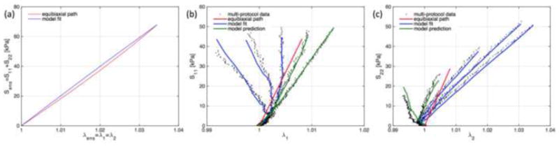
Representative experimental data on a tissue-analog sample with PAM gel with stiffness μm = 12 kPa. In the first parameter estimation step, the ensemble response to equibiaxial stretch is used to determine χ [(a), equibiaxial path as red line, fitted model as blue line], and subsequently, protocols 3–5 are employed to determine ηint [experimental data as black dots, model fits as blue lines in (b) and (c)]. As a final step, the determined parameters are employed in to predict the remaining protocols and validate the parameter estimation methodology [green lines in (b) and (c)].
The “apparent fiber stiffness” of undulated fibers when present in the NNW scaffold was found to be 4-fold higher than the stiffness of individual fibers as if acting alone and determined by the elastica framework and the FE simulations. Moreover, this reinforcement mechanism was modulated by the environment surrounding the scaffold as the fiber stiffness amplification factor increased with increases in stiffness of the impregnated PAM gel, up to a 20-fold increase with the stiffest PAM gel impregnated (Table 3 and Figure 7a). The increase in stiffness was apparently nonlinear. The impregnation of soft PAM gel does not appreciably change the apparent stiffness of the fibers, we observed a slight and non-statistically significant decrease from the baseline μm = 0 kPa. However, the amplification effect is substantial when PAM gel is stiffer than 24 kPa. Microstructurally, the presence of a stiffer environment surrounding the scaffold fibers restricts their deformation, possibly strengthens inter-connecting points in between them and these translate individually to the fiber level as fibers have shorter effective wavelength and amplitude, which accordingly to our elastica model, would result in a stiffer Pf vs. λf behavior.
Table 3.
Fiber stiffness amplification and interaction as a function of surrounding PAM gel stiffness. PAM gel stiffness is the first column is a group label with “target” stiffness, actual stiffness of the impregnating environment is listed in Table 1. A substantial increase in apparent fiber stiffness was observed with the impregnation of stiffer PAM gel surrounding the fibers. A stiffer surrounding environment also promotes higher magnitude interactions in between fibers.
| PAM shear modulus μm (kPa) |
n | fiber stiffness amplification χ(μm) (fold increase) |
fiber-fiber interaction ηint (μm) (kPa) |
|---|---|---|---|
| 0.0 | 4 | 4.4464 ± 0.6258 | 7,380.929 ± 20.847 |
| 3.8 | 4 | 3.1138 ± 0.3442 | 4,840.594 ± 954.413 |
| 8.0 | 5 | 3.8214 ± 1.1133 | 6,272.003 ± 2,586.152 |
| 12.0 | 5 | 5.6812 ± 0.8528 | 10,267.599 ± 2,021.273 |
| 19.0 | 3 | 6.4451 ± 0.5180 | 10,182.950 ± 1,180.192 |
| 24.0 | 3 | 13.2459 ± 1.7264 | 21,514.210 ± 3,289.930 |
| 42.0 | 3 | 14.5941 ± 2.9029 | 24,549.547 ± 3,545.079 |
| 48.0 | 3 | 20.7062 ± 1.3833 | 42,399.357 ± 3,439.207 |
|
| |||
| χ(μm) = 3.4902 e0.0374μm | ηint (μm) = 5559.7 e0.0405μm | ||
| R2 = 0.88587 | R2 = 0.88734 | ||
Figure 7.
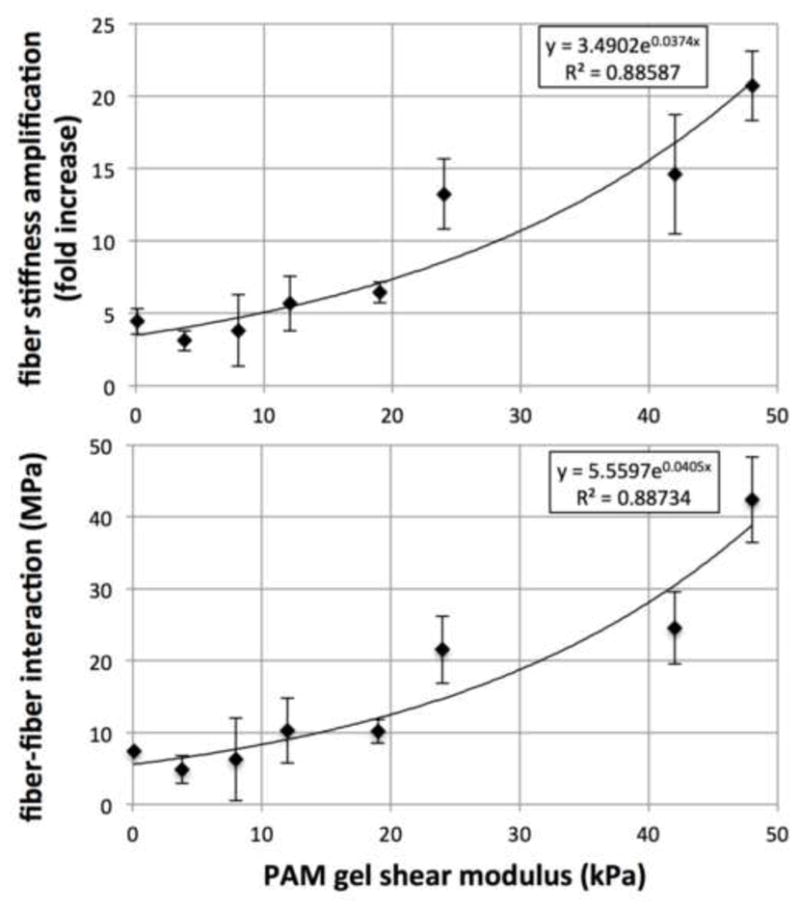
Modulation of effective fiber stiffness and fiber interaction vs. PAM gel shear modulus, χ (μm) and ηint (μm) respectively. Without any surrounding materials, scaffold fibers are effectively 4-fold stiffer than if acting alone. The addition of surrounding materials amplifies this reinforcement mechanism in a nonlinear fashion – softer gels were not able to trigger any stiffness amplification beyond this baseline, whereas substantial stiffness amplifications are observed when PAM gel of stiffness greater than 20 kPa surrounds the fibers. 20-fold fiber stiffness amplification was observed with the stiffer PAM gel, and a similar trend is observed in the magnitude of the fiber-fiber interaction term.
A similar trend was seen in the interaction term – the energy associated to fiber-fiber interactions increase as the stiffness of the PAM gel increases (Table 3 and Figure 7b). Fitting of experimental data to determine this parameter results in this contribution towards the total stored energy to be indeed negative and supports our hypothesis on the underlying micro-mechanism of fiber-fiber interactions. Firstly, fibers being compressed in the transverse direction of extensional strains collapse due to buckling and do not store mechanical energy (as prescribed in Equation (15)); and secondly, large amplitude translational displacement of buckled fibers occur in the direction of the extensional strain and the presence of a stiffer environment surrounding scaffold fibers promoting stronger cross-linking results in less mechanical energy being necessary to deform the sample along the extensional strain direction (when compared with a sample made from the hypothetical material that does not have fiber-fiber interactions). In experimental protocols where extensional stretches in one direction and shrinkage in the other are present and substantial (Figure 2), there exists a range of fiber orientations (shown in green, spanning from + γ to − γ) that will collapse with lateral shrinkage and boost fibers aligned with the extensional direction to extend further (or alternatively, reduce the amount of load necessary to achieve the same deformation). Lastly, specific forms for χ (μm) and ηint (μm) were chosen among fits that provided the best results. In particular, we have attempted polynomial fits of different orders, logarithmic fits of the form y = Aln(x) + B, and power-law fits of the form y = AxB, and we have found that an exponential fit of the form y = A eBx, where x corresponds to μm and y to χ(μm) and ηint (μm), provided the best R2 values of 0.88587 and 0.88734 respectively (Figure 7).
3.4 Estimation of mechanical properties of engineered extracellular matrix
The presented methodology allows the estimation of extracellular matrix stiffness in engineered tissue constructs obtained from short implant durations of pulmonary valve conduits. Histology was performed to evaluate the overall structure of the conduits at the post-incubation/pre-implantation (t = 0 day), and at explant at t = 1 day and t = 7 days (Figure 8). Scaffold volume fraction was computed from transmural H&E stained sections at the three time points (n = 4, 5 and 5 respectively, Table 4). Scaffold volume fraction decreased sharply during incubation (from ϕf = 0.0702 ± 0.0102 in virgin scaffolds to ϕf = 0.0460 ± 0.0041 and ϕf = 0.0397 ± 0.0064 at t = 0 and 1 day respectively). A second sharp decrease occurred from t = 1 day to t = 7 day (down to ϕf = 0.0298 ± 0.0046), which is corroborated qualitatively from inspection of the H&E images (Figure 8). Histology displayed signs of granulation with macrophage infiltration, though foreign body giant cells were minimal. Scaffold micro-morphology changed substantially after exposure to the in vivo milieu for 7 days with substantial reduction in scaffold volume fraction and organization.
Figure 8.
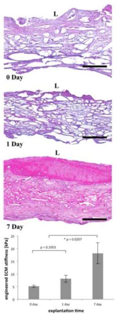
Representative transmural H&E histology of pulmonary valve conduits obtained post incubation (t = 0 day) and post-implantation in an ovine model (t = 1 and 7 day) of a parallel study [28, 29] (top) and ECM stiffness (bottom). Black scale bar represents 300 μm, L denotes the luminal, and collagen is stained in pale pink and cell nuclei in blue. The scaffold fibers are clearly noticeable at all time points. A substantial amount of void space is observed at the early time points, yet after 7 days of in vivo implantation, the engineered tissue was densely packed and a fair amount of inflammatory reaction on the lumen side is observed in this sample. ECM stiffness increased substantially after 7 days of in vivo implantation.
Table 4.
Estimation of the stiffness of engineered extracellular matrix in pulmonary conduits in an ovine model. Scaffold volume fraction decreases with implant time as fibers are degradable and absorbed by the host body. The stiffness of the produced ECM does not change appreciable from the values observed post-implantation during these first few days after implant.
| n | scaffold volume fraction ϕf |
engineered ECM stiffness μm (kPa) |
|
|---|---|---|---|
| pre-incubation | Eckert et al. (2011) | 0.0702 ± 0.0102 | |
| t = 0 day | 4 | 0.0460 ± 0.0041 | 5.173 ± 0.393 |
| t = 1 day | 5 | 0.0397 ± 0.0064 | 8.1318 ± 1.370 |
| t = 7 day | 4 | 0.0253 ± 0.0042 | 18.138 ± 4.144 |
The development of the tissue-analog model for the proper characterization of the fiber amplification and interaction terms allows the estimation of the shear modulus of the engineered ECM with biaxial testing data at each time point. The three central protocols were fit simultaneously with Equation (24) and the specific forms of Equations (25) to find parameter μm, now representing the stiffness of the ECM surrounding the scaffold fibers (Figure 8 and Table 4). At post-incubation, the stiffness of ECM was rather low (μm = 5.173 ± 0.393 kPa and μm = 8.1318 ±1.370 kPa at t = 0 day at t = 1 day respectively, but without significant statistical difference in between). However, a substantial and statistically significant increase in ECM stiffness was observed at t = 7 day when compared with post incubation values (up to μm = 18.138 ± 4.144 kPa).
4 Discussion
In the current study, we have developed a rigorous methodology that complements systematic experimentation with specialized theoretical modeling to expand our understanding of how these NNW scaffold-ET composites behave mechanically and how to quantify the mechanical properties of the de novo ECM. The ability to obtain reliable and robust measures that quantify de novo ECM would be pivotal in any study that aims to achieve any functional requirement for ET implants. The experimental methods we employed are standard procedures and were extensively employed in previous studies to characterize the mechanical response and the microstructure of collagenous soft tissues.
The novelty of the current approach lies in the choice of an appropriate modeling framework coupled to a modeling-designed systematic experimental program to validate and calibrate the model. The modeling effort was motivated by initial observations of Engelmayr et al. [25] on effective stiffness of ET constructs based on NNW scaffolds due to forming ECM. Our experimental program was based in well-established methods to emulate forming ECM in NNW scaffolds by impregnation with PAM gel. Most importantly, the theoretical development yielded critical insight into some particular features of these scaffolds, specifically the underlying mechanisms of fiber buckling, scaffold stiffness amplification, and fiber-fiber interaction behavior that were not possible to conjecture without the insight given by modeling, let alone describe or foresee a priori. As end result, we obtained a robust methodology to infer the stiffness of de novo ECM formed on a NNW scaffold, and employ such to quantify the quality of ETs obtained in vitro and in vivo in a concurrent study on engineered tissue pulmonary valves in an ovine model [28]. In the current study we have employed planar deformations; however, our methodology could be used in more complex situations wherein the geometry is more complex such as conduits or other organoids.
4.1 Single fiber response
The elastica framework captures remarkably well the tensile response of the undulated fibers that compose the NNW scaffold (Figure 3). The analytical treatment of individual NNW scaffold fibers within the elastica framework, even with its inherent assumptions, captures their behavior with remarkable accuracy in comparison with the FE simulations (cf. Figure 4). However, the elastica framework yields much lighter/simpler computational algorithms (in comparison to FE simulations) and is very powerful for the parametric study of the influence of geometric features of NNW scaffolds fibers, specifically changes in crimping amplitude and fiber wavelength.
With the elastica framework, we have estimated the stiffness of the undulated fibers in the NNW scaffold in their small strain regime (strictly speaking, the slope Pf vs. λf near the origin) and use it in constitutive model of fibers in our NNW scaffold structural model. Parametric studies on elastica parameters were key in understanding the mechanisms of fiber stiffness amplification that occur when fibers are not acting alone but are indeed part of the complex microstructure of NNW scaffolds. Specifically, we have observed that decreases either in amplitude a0 or in characteristic wavelength L0 result in stiffer fiber responses and in a decrease of the stretch at which full locking engages (λs in Figure 3b and Figure 4a). This behavior is in agreement with the previous analysis of Engelmayr et al. [13] where changes in effective amplitude and wavelength occurring due to fiber-fiber cross-over points served as the underlying mechanism for the observed increases in effective bending stiffness of the NNW scaffold, and here serve as the basis for the fiber stiffness amplification factor in our structural model (the term χ in Equation (14)). The “slack” stretch λs is mainly defined by the initial length of fibers, and thus indirectly through their amplitude and characteristic wavelength. Beyond this region and as expected, the elastica framework recovers the extensional stiffness of the material, i.e. its elastic modulus, mainly as the fiber becomes fully-locked with barely any undulation remaining to be uncoiled, and its characteristic “terminal” stiffness is reached. However, we have observed that when subjected to compression, the elastica model is not able to capture any sort of nonlinear phenomena as the stiffness at small strains extends into the compressive regime without change (Figure 3).
The elastica framework fails to capture the proper behavior of undulated fibers under compression mainly due to the underlying assumptions made a priori in order to render the analytical treatment feasible. The imposition of analytical restrictions on the solution space of the governing equations is a common technique in classical linearized elasticity or fluid mechanics, however correct solutions may be automatically left out and not sought, and consequently, incorrect solutions found.
Two main restrictions on motions are assumed in the elastica framework: (1) the sinusoidal fiber remains in a sinusoidal configuration; and (2) the fiber remains in plane. The self-similarity assumption is responsible for maintaining the same small strain stiffness into compression. Our finite element simulations demonstrate that there is a substantial departure from this stiffness, specifically a substantial reduction in modulus happens after a certain compressive displacement is imposed (cf. Figure 4, for stretches smaller than λ ≈ 0.95). Beyond a certain compressive deformation, the fiber does not remain in a sinusoidal configuration (cf. Figure 5) as substantial changes in curvature start to occur in the “corners” of the sinusoid and this phenomena is not captured by the elastica framework (which will always consider the compressed fiber to be in a sinusoidal configuration). More important is the assumption that the fiber remains in plane upon compression. This hinders the search for possible solutions involving out-of-plane motion, specifically happening with buckling instabilities. Finite element simulations are able to be left unconstrained and these modes of deformation are possible to be simulated. Indeed, we have observed that under compression, the undulated fiber buckles and after such phenomena, it collapses onto itself with a negligible slope on its force vs. displacement relationship (cf. Figure 5)
To summarize, the analysis of the single fiber response within the elastica framework and with the aid of FE simulations allowed us:
To estimate the stiffness of undulated fibers under extension based on the characteristics of their initial configurations, specifically a0 and L0, and to characterize their tensile behavior as linear with a known modulus (cf. Equation (15) for λf >1).
To have a deeper understanding on how the geometric configuration of the undulated fiber influences its stiffness under tension, and to realize that when embodied within NNW scaffolds where a large number of fiber-fiber cross-over points are introduced as fiber entangle within themselves, substantial decreases of effective amplitude and wavelength will be responsible for an apparent increase in fiber stiffness (cf. term χ in Equation (14)).
To estimate that fibers possess negligible stiffness under compression and thus no ability to store mechanical energy in this regime (cf. Equation (15) for λf <1).
4.2 NNW scaffold mechanical response
Our structural modeling effort is phenomenologically driven, starts from the fiber-level, and is an extension of the stochastic, tissue-level meso-structural models first pioneered by Lanir [49] and used/extended in diverse applications by our group [35, 37, 47, 50]. However, here we did not adopt the concept of fiber ensembles (as in collagenous soft tissues) as such supra-structures do not exist in NNW scaffolds, and fibers do not act independently as fiber-fiber interactions play a major role in NNW scaffold mechanics. We then utilized an extensive experimental dataset with a comprehensive set of planar biaxial stress-controlled protocols to evaluate the mechanical response of NNW scaffolds alone and when surrounded by de novo ETs.
NNW scaffolds exhibited consistent anisotropy, with the stiffer direction being the preferred direction of fiber alignment (Figure 6b and c), and a mild nonlinear response within the small stretches tested. Typical strains were under 5%, and the mechanisms of extensional deformation within this regime are mainly driven by straightening of crimped fibers [15]. Previous studies have demonstrated that the out-of-plane compressive stiffness of nonwoven PGA scaffolds is relatively low [51], which certainly indicates a substantial change in the nature of the micro-mechanisms associated with this mode of deformation. Needling density is a manufacturing parameter that has been extensively studied (cf. Hearle and co-workers [14, 15, 52]) and demonstrated to modulate the effective length of fiber segments and crimp amplitude, and consequently influence the fiber behavior at in micro-scale and bulk properties of the scaffold. While scaffold mechanical response can be quantified and determined directly from experiments, the fiber behavior cannot and a modeling framework is the tool that transfers the measurable experimental data into microstructural insight. With the aid of our modeling framework, we were able to investigate three rather specific characteristics of NNW scaffolds.
4.2.1 NNW scaffold fibers have improved effective stiffness
Undulated fibers when present in NNW scaffold become apparently stiffer that their individual fiber response. Specifically, in the virgin scaffold, fibers were apparently 4-fold stiffer than as if acting alone, and this fiber stiffness amplification is due to the introduction of fiber-fiber cross-over points that reduce the effective fiber amplitude and wavelength during the manufacturing process. This reinforcement mechanism, i.e. changes of effective crimp amplitude and wavelength, was initially proposed by Engelmayr et al. [25] to explain the substantial reinforcement effect the authors observed in NNW scaffolds seeded with ovine vascular smooth muscle cells. ET construct stiffness did not increase appreciably immediately after the 30 hour seeding period (when compared with unseeded scaffolds). Yet after 3 weeks of incubation either under static or dynamically flexed conditions, the flexural stiffness of the ET construct increased 351% and 429% when compared to unseeded scaffolds and a strong positive relation between construct stiffness and collagen concentration was observed. The authors were unable to explain this significant stiffness amplification effect based on the simple rule-of-mixtures given the relatively low amount of collagen present (but yet resulting in such substantial increase in stiffness), and proposed the existence of an additional reinforcing mechanism due to an increase in the number of effective rigidly-bonded fiber-fiber cross-over points, with a concomitant decrease in arc length of curved segments spanning in between these points, and thus effectively, apparent fiber stiffness [24].
4.2.2 NNW scaffold fibers are not able to bear compressive loads
As a first iteration in our study, we have hypothesized that fibers did offer resistance to compression and set the compressive stiffness to equal the tensile stiffness as obtained with the elastica framework. Specifically, we had initially considered the first term of Equation (15) to hold for compressive regimes as well. However, our experimental dataset did not support such hypothesis as it was definitely unable to describe the behavior observed in asymmetric protocols where samples are loaded substantially more in one direction than the other and consequently extend in one direction while shrinking in the other. Specifically, a model that assumes fibers to offer resistance to compression will predict compressive stretches in the transverse directions of these asymmetric protocols, which we have observed experimentally not to occur, yet when used in protocols on which resulting stretches are tensile in both directions, such model works fine (Figure 9). This suggests that fibers in NNW scaffolds cannot withstand compressive stresses and likely buckle and motivated our study at the individual fiber level with FE simulations (Figure 5).
4.2.3 NNW scaffold fibers extensively interact
Another interesting feature of the mechanical behavior of NNW scaffolds is their remarkable anisotropic behavior that stems from fiber-fiber interactions. While the exact underlying structural mechanisms of interaction remains uncharacterized, we have found that an interaction term of the form of Equation (21) had to be included to property fit the experimental data. The need to include this extra contribution was more appreciable in protocols that involved compressive strains of the construct, i.e. stretching in one direction and shrinkage the in the other. Most interestingly, the resulting interaction term was negative for all samples tested, meaning that the interaction in between fibers has the ability to decrease the amount of elastic energy stored in the material. Put another way, less energy is necessary to be imparted to the material to deform it up to certain state (when compared with a similar material where the interactions do not exist). Although unusual, this is not surprising – e.g. Humphrey and Yin [53, 54] based on biaxial experiments on excised myocardium found the need to include a negative parameter in an interaction term (specifically, a multiplicative interaction in between I1 and I4) to properly describe experimental data and verified that such would not violate thermodynamic restrictions on their material model. The appearance of this “negative-valued” interaction stimulated a substantial effort in developing hypotheses for the underlying structural mechanism of the fiber-fiber interactions. Specifically, we hypothesize that: (1) segments of fibers collapsing in the direction of shrinkage will undergo substantial translational motion in the extensional direction; (2) due to extensive fiber-fiber cross-over points in between fibers in the NNW scaffold, these motions will complement the extensional deformation of crimped fibers aligned in the extensional direction; and lastly (3) less force/energy will be necessary to be imparted to achieve a certain deformation (Figure 2). Further full 3D models based on actual reconstructed fiber models (as in Eckert et al. [55]) will likely be necessary to more fully understand these mechanisms.
4.3 NNW scaffold/ET composite mechanical response
Our framework separates the mechanical contribution of the scaffold from the materials surrounding it, and its ultimate goal is the quantitative determination of the mechanical properties of formed ECM. This is possible in part due to the experimental dataset acquired with the NNW scaffold/PAM gel tissue-analog with highly-controlled and pre-specified PAM gel stiffness that ranged the expected values to occur in engineered ECM. As in several of our previous studies, we found that the PAM gel or the engineered ECM could be well modeled as an isotropic neo-Hookean material, particularly at the strain regimes of interest and at the early stages of incubation or implantation [37]. Anisotropy of the ECM phase is a straightforward extension from the modeling and experimental standpoint – the former would result in a different specific form of Equation (12) whereas the later would involve biaxial testing data reduction to more than one single parameter characterizing the anisotropic response of de novo ECM. Overall, we observed that the tissue-analogs become generally much stiffer when impregnated with PAM gel. The underlying mechanisms for such are unknown, but our hypothesis is that the surrounding environment improves the number and strength of fiber-fiber crossover points and enhances the fiber-fiber interactive effects in NNW scaffolds. Even without any surrounding material, fibers in a scaffold show a substantial increase in apparent stiffness (as mentioned above, 4.5-fold stiffer, however it must be stressed that mechanical testing of non-impregnated scaffolds is conceptually different). When surrounding material is present, the effective stiffness of the fibers increases dramatically (up to 20-fold stiffer when a PAM gel of 48 kPa is impregnated in the scaffold, Figure 7). The increase in apparent stiffness follows an exponential behavior with softer gels not being able to trigger this stiffness amplification mechanism appreciably. On the other hand, the stiffness of the surrounding environment certainly influences not only the buckling behavior (as in buckling of beams resting on elastic foundations) but also the extension of sinusoidal elasticas; however, the difference in moduli from the scaffold fiber to the surrounding environment is so large that small differences on the latter will not have much impact on changing the critical load or the effective stiffness of a sinusoidal fiber.
Similarly, the magnitude of the interaction term follows a similar trend – as expected, when fibers are interconnected with “stronger” fiber-fiber cross-over points, the “softening” effect in the extensional direction due to collapsing of fibers in the direction of shrinkage become more appreciable.
4.4 Characterization of engineered ECM mechanical response
The most striking phenomena observed in our study is the substantial stiffness amplification that occurs in this class of tissue engineering scaffolds due to the surrounding environment (impregnated PAM gel in our tissue-analog model or engineered ECM in ET applications). This phenomenon has been previously reported by Engelmayr et al. [25] and this observation was the motivational driver for the current study. After the 30 hour incubation period, the authors have observed histologically dense cellularity and substantial accretion of sulfated glycosaminoglycans but no collagen could be detected biochemically. An important surrounding environment did exist, but was unable to modulate the reinforcement of the stiffness of the construct, which in our tissue-analog would correspond to impregnation with PAM gel of negligible stiffness and not being sufficiently strong to trigger the fiber stiffness amplification mechanisms. In the present study, we have systematically characterized these reinforcement mechanisms with highly controllable tissue-analogs to obtain specific forms for the fiber amplification factor χ (μm) and for the interaction term ηint (μm) (cf. Equation (25)). With such, we estimated the ECM properties obtained after incubation of pulmonary valve conduits and after their short-term implantation in an ovine model in a concurrent study by our group and collaborators [28]. We have observed a 3.5 fold increase of ECM stiffness from post-incubation (μm = 5.173 ± 0.393 kPa) to post-implantation after t = 7 days of in vivo function and remodeling (μm = 18.138 ± 4.144 kPa), and no statistically significant differences from post-incubation to t =1 day (Figure 8 and Table 4). The mean errors associated with these results also demonstrate the high degree of variability as soon as the in vivo milieu comes into play. However, this increase is substantial and statistically significant, and clearly demonstrates the feasibly of the NNW scaffolds as a suitable material to engineer tissue – not only an appreciable ECM stiffness is observed after static incubation, but also this stiffness is augmented substantially with the in vivo stimulation of biological, biochemical and biomechanical factors of the physiological native environment. Histological imaging corroborates these findings (Figure 8, H&E staining with collagen in pale pink) – not much differences are observed in between t = 0 day and t = 1 day, however, sections of the conduits at t = 7 days show striking differences with some inflammatory reaction in the lumen side developing. Void spaces are present in between scaffold fibers and forming tissue, however much less void space is present in the later time point as substantial amount of tissue compaction, ECM production and cross-linking, and mechanical functionalization of the de novo tissue is known to occur [4, 56].
The scaffold phase is significantly present in all 3 time points, which demonstrate that the scaffold contribution to the overall mechanics of the engineered tissue contract is still major. However, due to the formation of dense tissue and the environment of in vitro incubation and in vivo function, the scaffold volume fraction has decreased from ϕf ≈ 7% (Table 4) to 4.6%, 4.0% and 2.5% at post-incubation, t =1 day and t = 7 days respectively. The methodology to determine the stiffness of the ECM phase is sensitive to this measurement (as the stiffness of the scaffold is much higher than the expected stiffness of the ECM phase, and thus dominate the mechanical response of the composite being tested). Thus, the volume fraction of the scaffold must be accurately determined from digital image analysis of histological sectioning. Scaffold degradation introduces one layer of complexity into this problem that is not formally incorporated in our modeling framework (we account it with a decreasing mass fraction of the scaffold phase that we are able to rigorous quantify on a per-sample basis from imaging analysis of histological slides). While scaffold breakdown, and consequently, a substantial reduction of the mechanical integrity of the fibrous nature of the NNW scaffold occurs after long term implantation (we observed degradation timescales on the order of months in this particular system, cf. [28, 29]), we are confident that the microstructure and the mechanical contribution of the NNW scaffold is still present at 7 days of in vivo incubation. A scaffold that would not degrade would certainly be ideal for the validation of our methodology, however ETs are often grown in degradable scaffold where the degradation profile of the scaffold promotes a favorable pro-synthetic response as the mechanical integrity shifts from the scaffold to the developing tissues, either in vitro or in vivo.
The determination of the contribution of the ECM in a engineered tissue construct that is composed of remaining scaffold and forming tissue is a difficult task mainly because both phases are tightly coupled and difficult to separate [27]. However, there is substantial interest in quantifying ECM stiffness, as such measure would be extremely beneficial to: (1) improve our understanding of the process of tissue accretion and remodeling in any ET application, either in vitro during incubation or in vivo function after implantation; (2) aid the design of ET implants and the specification of their functional requirements, helping the development of incubation and conditioning protocols to achieve those and providing a quantitative basis for the prediction of in vivo post-implantation function. In the current study, we develop a semi-indirect method to quantify the stiffness of ECM deposited in our specific NNW scaffold system. This approach relies on the systematic dataset obtained a priori with our tissue-analog and is rather specific to the present study. Regardless, a reliable quantification of the enhancement of ECM stiffness from post-incubation to explanation after 7 days of in vivo function was proposed and may prove beneficial in future studies.
4.5 Limitations
The main limitation of this study is that the exact micro-mechanical mechanisms of fiber-fiber interactions in NNW scaffolds are yet to be fully characterized and our structural modeling effort remains largely phenomenologically driven. Our methodology is microstructurally informed but still resulting in a macroscale model. We do not include micro-level effects as this would make the model unwieldy in complexity for the current purpose (to infer the stiffness of de novo ECM). Extensions of the current modeling ideas for scaffold design is quite relevant and planned for future studies.
Our methodology to quantify the stiffness of the de novo ECM is “indirect” and relies on the calibration of the fiber stiffness amplification and fiber-fiber interaction factors with the biaxial testing data collected with several tissue analogs composites of NNW scaffold-PAM gel of known stiffness – if a different scaffold system is employed (e.g. different fiber needling, crimping, density, etc.), these experiments would have to be repeated and their parameters and specific forms could possibly be different. However, this does not detract from the utility of this approach. In addition, we do not incorporate any phenomena of scaffold degradation besides the reduction of its volume fraction measured from histological analysis of in vivo samples, and we do not attempt to establish any framework to describe the growth and development of the forming tissue (subject of future work).
As in many physiological systems, multiscale modeling approaches yielding a complete micromechanical description of fiber-fiber-ECM interactions using 3D models of fibers could prove to be beneficial to fully understand and formulate the complex nature of these materials. The ultimate success of these approaches to study the microscales of synthetic and native biomaterials rely on an in-depth understanding of the underlying fibrous (scaffold and ECM) and cellular constituents and how they rearrange under mechanical loading. These approaches are difficult (or possibly, currently unfeasible), not only due to the scarcity of data to construct them but also due to theoretical and practical challenges associated in casting their analytical and computational formulations. Yet, we are entering an era on which high performance computing and modeling allows for the creation of complete 3D models of representative volume elements of materials with complex microstructure based on highly-detailed histological data (or data from other imaging sources) and their results will provide substantial insight on the microstructural function of such complex materials and how large scale forces transduce to cellular levels. Modeling strategies as the one proposed here can provide future utility in experimental studies as well as inform ongoing micromechanical efforts.
5 Conclusions
The proposed model captures the salient features of the behavior of engineered tissue constructs based on NNW scaffolds, specifically the reinforcing effect of the surrounding material that leads to a substantial amplification of apparent fiber stiffness, the collapse of fibers aligned in the direction of shrinkage and their general inability to withstand compression, and the interaction in between fiber ensembles with collapsing fibers aiding the extension of the material in their transversal direction. We focus on a sufficiently generalized approach for matrix-reinforced-scaffolds, and demonstrate how can a theoretical framework be employed in conjunction with an experimental program to provide significant and relevant measures such as ECM stiffness that are crucial for any effort in more rational design and manufacturing of engineered tissues to operate under highly demanding mechanical environments.
The results of the current study demonstrate that the deformation and configurational changes of curved fiber segments is fundamental to the mechanical response of NNW scaffolds. On one hand, an appreciable reinforcement effect is observed due to forming tissues, and in particular, if those are of sufficient stiffness. This would certainly be beneficial during the early stages of in vivo function when the mechanical integrity of an ET implant should be carried mainly by the scaffold. On the other hand, it is expected that the deformation of these segments will play important roles in determining the microscale strains imparted to the cells embedded in their ECM. These results leave open the possibility of significant cell and ECM strain amplifications due to the large translational motions and transversal deflections of curved segments occurring at the micro-scale, even though obtained within small strain regimes. Such strain amplification phenomena would have important ramifications for mechano-stimulation of cells seeded in NNW scaffolds.
Statement of Significance.
Regenerative medicine has the potential to fully restore diseased tissues or entire organs with engineered tissues. Needled-nonwoven scaffolds can be employed to serve as the support for their growth. However, there is a lack of understanding of the mechanics of these materials and their interactions with the forming tissues. We developed a mathematical model for these scaffold-tissue composites to quantify the mechanical properties of the forming tissues. Firstly, these measurements are pivotal to achieve functional requirements for tissue engineering implants; however, the theoretical development yielded critical insight into particular mechanisms and behaviors of these scaffolds that were not possible to conjecture without the insight given by modeling, let alone describe or foresee a priori.
Acknowledgments
This study was supported in part by NIH grant no. R01 HL068816, HL089750, HL119297, HL63954 and HL108330 (to M.S.S). All authors of References [28, 29] must be acknowledged, in particular Drs. Danielle Gottlieb and Chad E. Eckert for performing the experimental programs that support the current research. We thank and acknowledge the constructive suggestions made by three anonymous reviewers.
Footnotes
Publisher's Disclaimer: This is a PDF file of an unedited manuscript that has been accepted for publication. As a service to our customers we are providing this early version of the manuscript. The manuscript will undergo copyediting, typesetting, and review of the resulting proof before it is published in its final citable form. Please note that during the production process errors may be discovered which could affect the content, and all legal disclaimers that apply to the journal pertain.
References
- 1.Mao AS, Mooney DJ. Regenerative medicine: Current therapies and future directions. Proc Natl Acad Sci U S A. 2015;112(47):14452–9. doi: 10.1073/pnas.1508520112. [DOI] [PMC free article] [PubMed] [Google Scholar]
- 2.Hansen A, Eder A, Bonstrup M, Flato M, Mewe M, Schaaf S, Aksehirlioglu B, Schwoerer AP, Uebeler J, Eschenhagen T. Development of a drug screening platform based on engineered heart tissue. Circ Res. 2010;107(1):35–44. doi: 10.1161/CIRCRESAHA.109.211458. [DOI] [PubMed] [Google Scholar]
- 3.Boudou T, Legant WR, Mu A, Borochin MA, Thavandiran N, Radisic M, Zandstra PW, Epstein JA, Margulies KB, Chen CS. A microfabricated platform to measure and manipulate the mechanics of engineered cardiac microtissues. Tissue Eng Part A. 2012;18(9–10):910–9. doi: 10.1089/ten.tea.2011.0341. [DOI] [PMC free article] [PubMed] [Google Scholar]
- 4.Schutte SC, Chen Z, Brockbank KG, Nerem RM. Tissue engineering of a collagen-based vascular media: Demonstration of functionality. Organogenesis. 2010;6(4):204–11. doi: 10.4161/org.6.4.12651. [DOI] [PMC free article] [PubMed] [Google Scholar]
- 5.de Lange WJ, Hegge LF, Grimes AC, Tong CW, Brost TM, Moss RL, Ralphe JC. Neonatal mouse-derived engineered cardiac tissue: a novel model system for studying genetic heart disease. Circ Res. 2011;109(1):8–19. doi: 10.1161/CIRCRESAHA.111.242354. [DOI] [PMC free article] [PubMed] [Google Scholar]
- 6.Kim BS, Mooney DJ. Development of biocompatible synthetic extracellular matrices for tissue engineering. Trends Biotechnol. 1998;16(5):224–30. doi: 10.1016/s0167-7799(98)01191-3. [DOI] [PubMed] [Google Scholar]
- 7.Nelson CM, Bissell MJ. Of extracellular matrix, scaffolds, and signaling: tissue architecture regulates development, homeostasis, and cancer. Annu Rev Cell Dev Biol. 2006;22:287–309. doi: 10.1146/annurev.cellbio.22.010305.104315. [DOI] [PMC free article] [PubMed] [Google Scholar]
- 8.Badylak SF, Taylor D, Uygun K. Whole-organ tissue engineering: decellularization and recellularization of three-dimensional matrix scaffolds. Annu Rev Biomed Eng. 2011;13:27–53. doi: 10.1146/annurev-bioeng-071910-124743. [DOI] [PMC free article] [PubMed] [Google Scholar]
- 9.Badylak SF. The extracellular matrix as a biologic scaffold material. Biomaterials. 2007;28(25):3587–93. doi: 10.1016/j.biomaterials.2007.04.043. [DOI] [PubMed] [Google Scholar]
- 10.Williams C, Liao J, Joyce EM, Wang B, Leach JB, Sacks MS, Wong JY. Altered structural and mechanical properties in decellularized rabbit carotid arteries. Acta Biomater. 2009;5(4):993–1005. doi: 10.1016/j.actbio.2008.11.028. [DOI] [PMC free article] [PubMed] [Google Scholar]
- 11.Simon P, Kasimir MT, Seebacher G, Weigel G, Ullrich R, Salzer-Muhar U, Rieder E, Wolner E. Early failure of the tissue engineered porcine heart valve SYNERGRAFT in pediatric patients. Eur J Cardiothorac Surg. 2003;23(6):1002–6. doi: 10.1016/s1010-7940(03)00094-0. discussion 1006. [DOI] [PubMed] [Google Scholar]
- 12.Freed LE, Vunjak-Novakovic G, Biron RJ, Eagles DB, Lesnoy DC, Barlow SK, Langer R. Biodegradable polymer scaffolds for tissue engineering. Biotechnology (N Y) 1994;12(7):689–93. doi: 10.1038/nbt0794-689. [DOI] [PubMed] [Google Scholar]
- 13.Engelmayr GC, Jr, Sacks MS. A structural model for the flexural mechanics of nonwoven tissue engineering scaffolds. Journal of biomechanical engineering. 2006;128(4):610–22. doi: 10.1115/1.2205371. [DOI] [PubMed] [Google Scholar]
- 14.Hearle JWS, Purdy AT. The structure of needle punched fabric. Fibre Science and Technology. 1971;4(2):81–100. [Google Scholar]
- 15.Hearle JWS, Purdy AT. On the nature of deformation of needled fabrics. Fibre Science and Technology. 1972;5(2):113–128. [Google Scholar]
- 16.Kim BS, Mooney DJ. Scaffolds for engineering smooth muscle under cyclic mechanical strain conditions. Journal of biomechanical engineering. 2000;122(3):210–5. doi: 10.1115/1.429651. [DOI] [PubMed] [Google Scholar]
- 17.Mol A, Bouten CV, Zund G, Gunter CI, Visjager JF, Turina MI, Baaijens FP, Hoerstrup SP. The relevance of large strains in functional tissue engineering of heart valves. Thorac Cardiovasc Surg. 2003;51(2):78–83. doi: 10.1055/s-2003-38993. [DOI] [PubMed] [Google Scholar]
- 18.Sutherland FW, Perry TE, Yu Y, Sherwood MC, Rabkin E, Masuda Y, Garcia GA, McLellan DL, Engelmayr GC, Jr, Sacks MS, Schoen FJ, Mayer JE., Jr From stem cells to viable autologous semilunar heart valve. Circulation. 2005;111(21):2783–91. doi: 10.1161/CIRCULATIONAHA.104.498378. [DOI] [PubMed] [Google Scholar]
- 19.Hoerstrup SP, Sodian R, Daebritz S, Wang J, Bacha EA, Martin DP, Moran AM, Guleserian KJ, Sperling JS, Kaushal S, Vacanti JP, Schoen FJ, Mayer JE., Jr Functional living trileaflet heart valves grown in vitro. Circulation. 2000;102(19 Suppl 3):III44–9. doi: 10.1161/01.cir.102.suppl_3.iii-44. [DOI] [PubMed] [Google Scholar]
- 20.Oberpenning F, Meng J, Yoo JJ, Atala A. De novo reconstitution of a functional mammalian urinary bladder by tissue engineering. Nat Biotechnol. 1999;17(2):149–55. doi: 10.1038/6146. [DOI] [PubMed] [Google Scholar]
- 21.Niklason LE, Gao J, Abbott WM, Hirschi KK, Houser S, Marini R, Langer R. Functional arteries grown in vitro. Science. 1999;284(5413):489–93. doi: 10.1126/science.284.5413.489. [DOI] [PubMed] [Google Scholar]
- 22.Gooch KJ, Blunk T, Courter DL, Sieminski AL, Vunjak-Novakovic G, Freed LE. Bone morphogenetic proteins-2, -12, and -13 modulate in vitro development of engineered cartilage. Tissue Eng. 2002;8(4):591–601. doi: 10.1089/107632702760240517. [DOI] [PubMed] [Google Scholar]
- 23.Freeston WD, Platt MM. Mechanics of Elastic Performance of Textile Materials. 16. Bending Rigidity of Nonwoven Fabrics. Text Res J. 1965;35(1):48. [Google Scholar]
- 24.Engelmayr GC, Jr, Sacks MS. Prediction of extracellular matrix stiffness in engineered heart valve tissues based on nonwoven scaffolds. Biomechanics and modeling in mechanobiology. 2008;7(4):309–21. doi: 10.1007/s10237-007-0102-1. [DOI] [PubMed] [Google Scholar]
- 25.Engelmayr GC, Jr, Rabkin E, Sutherland FW, Schoen FJ, Mayer JE, Jr, Sacks MS. The independent role of cyclic flexure in the early in vitro development of an engineered heart valve tissue. Biomaterials. 2005;26(2):175–87. doi: 10.1016/j.biomaterials.2004.02.035. [DOI] [PubMed] [Google Scholar]
- 26.Soares JS, Sacks MS. A triphasic constrained mixture model of engineered tissue formation under in vitro dynamic mechanical conditioning. Biomechanics and modeling in mechanobiology. 2016;15(2):293–316. doi: 10.1007/s10237-015-0687-8. [DOI] [PMC free article] [PubMed] [Google Scholar]
- 27.D’Amore A, Soares JS, Stella JA, Zhang W, Amoroso NJ, Mayer JE, Jr, Wagner WR, Sacks MS. Large strain stimulation promotes extracellular matrix production and stiffness in an elastomeric scaffold model. J Mech Behav Biomed Mater. 2016;62:619–635. doi: 10.1016/j.jmbbm.2016.05.005. [DOI] [PMC free article] [PubMed] [Google Scholar]
- 28.Gottlieb D, Kunal T, Emani S, Aikawa E, Brown DW, Powell AJ, Nedder A, Engelmayr GC, Jr, Melero-Martin JM, Sacks MS, Mayer JE., Jr In vivo monitoring of function of autologous engineered pulmonary valve. The Journal of thoracic and cardiovascular surgery. 2010;139(3):723–31. doi: 10.1016/j.jtcvs.2009.11.006. [DOI] [PubMed] [Google Scholar]
- 29.Eckert CE, Mikulis BT, Gottlieb D, Gerneke D, LeGrice I, Padera RF, Mayer JE, Schoen FJ, Sacks MS. Three-dimensional quantitative micromorphology of pre- and post-implanted engineered heart valve tissues. Annals of biomedical engineering. 2011;39(1):205–22. doi: 10.1007/s10439-010-0162-8. [DOI] [PMC free article] [PubMed] [Google Scholar]
- 30.Garikipati K, Goktepe S, Miehe C. Elastica-based strain energy functions for soft biological tissue. J Mech Phys Solids. 2008;56(4):1693–1713. [Google Scholar]
- 31.Freed AD, Doehring TC. Elastic model for crimped collagen fibrils. J Biomech Eng-T Asme. 2005;127(4):587–593. doi: 10.1115/1.1934145. [DOI] [PubMed] [Google Scholar]
- 32.Billiar KL, Sacks MS. Biaxial mechanical properties of the natural and glutaraldehyde treated aortic valve cusp--Part I: Experimental results. Journal of biomechanical engineering. 2000;122(1):23–30. doi: 10.1115/1.429624. [DOI] [PubMed] [Google Scholar]
- 33.Soulhat J, Buschmann MD, Shirazi-Adl A. A fibril-network-reinforced biphasic model of cartilage in unconfined compression. J Biomech Eng-T Asme. 1999;121(3):340–347. doi: 10.1115/1.2798330. [DOI] [PubMed] [Google Scholar]
- 34.Soltz MA, Ateshian GA. A conewise linear elasticity mixture model for the analysis of tension-compression nonlinearity in articular cartilage. J Biomech Eng-T Asme. 2000;122(6):576–586. doi: 10.1115/1.1324669. [DOI] [PMC free article] [PubMed] [Google Scholar]
- 35.Sacks MS. Incorporation of experimentally-derived fiber orientation into a structural constitutive model for planar-collagenous tissues. J Biomech Eng-T Asme. 2003;125(2):280–287. doi: 10.1115/1.1544508. [DOI] [PubMed] [Google Scholar]
- 36.Holzapfel GA, Gasser TC, Ogden RW. Comparison of a multi-layer structural model for arterial walls with a fung-type model, and issues of material stability. J Biomech Eng-T Asme. 2004;126(2):264–275. doi: 10.1115/1.1695572. [DOI] [PubMed] [Google Scholar]
- 37.Sacks MS, Zhang W, Wognum S. A novel fibre-ensemble level constitutive model for exogenous cross-linked collagenous tissues. Interface focus. 2016;6(1):20150090. doi: 10.1098/rsfs.2015.0090. [DOI] [PMC free article] [PubMed] [Google Scholar]
- 38.Avazmohammadi R, Hill M, Simon M, Zhang W, Sacks M. A novel constitutive model for passive right ventricular myocardium: evidence for myofiber-collagen fiber mechanical coupling. Biomechanics and modeling in mechanobiology. doi: 10.1007/s10237-016-0837-7. ((accepted)) [DOI] [PMC free article] [PubMed] [Google Scholar]
- 39.Holzapfel GA. Nonlinear solid mechanics : a continuum approach for engineering. Wiley; Chichester ; New York: 2000. [Google Scholar]
- 40.Merodio J, Ogden RW. The influence of the invariant I-8 on the stress-deformation and ellipticity characteristics of doubly fiber-reinforced non-linearly elastic solids. Int J Nonlinear Mech. 2006;41(4):556–563. [Google Scholar]
- 41.Engler AJ, Griffin MA, Sen S, Bonnemann CG, Sweeney HL, Discher DE. Myotubes differentiate optimally on substrates with tissue-like stiffness: pathological implications for soft or stiff microenvironments. The Journal of cell biology. 2004;166(6):877–87. doi: 10.1083/jcb.200405004. [DOI] [PMC free article] [PubMed] [Google Scholar]
- 42.Engelmayr GC, Jr, Papworth GD, Watkins SC, Mayer JE, Jr, Sacks MS. Guidance of engineered tissue collagen orientation by large-scale scaffold microstructures. Journal of biomechanics. 2006;39(10):1819–31. doi: 10.1016/j.jbiomech.2005.05.020. [DOI] [PubMed] [Google Scholar]
- 43.Sacks MS, Smith DB, Hiester ED. A small angle light scattering device for planar connective tissue microstructural analysis. Annals of biomedical engineering. 1997;25(4):678–89. doi: 10.1007/BF02684845. [DOI] [PubMed] [Google Scholar]
- 44.Zhang W, Feng Y, Lee CH, Billiar KL, Sacks MS. A Generalized Method for the Analysis of Planar Biaxial Mechanical Data Using Tethered Testing Configurations. J Biomech Eng-T Asme. 2015;137(6) doi: 10.1115/1.4029266. [DOI] [PMC free article] [PubMed] [Google Scholar]
- 45.Sacks MS. Biaxial mechanical evaluation of planar biological materials. J Elasticity. 2000;61(1–3):199–246. [Google Scholar]
- 46.Lanir Y. A structural theory for the homogeneous biaxial stress-strain relationships in flat collagenous tissues. Journal of biomechanics. 1979;12(6):423–36. doi: 10.1016/0021-9290(79)90027-7. [DOI] [PubMed] [Google Scholar]
- 47.Fata B, Zhang W, Amini R, Sacks MS. Insights Into Regional Adaptations in the Growing Pulmonary Artery Using a Meso-Scale Structural Model: Effects of Ascending Aorta Impingement. J Biomech Eng-T Asme. 2014;136(2) doi: 10.1115/1.4026457. [DOI] [PMC free article] [PubMed] [Google Scholar]
- 48.Smith DB, Sacks MS, Vorp DA, Thornton M. Surface geometric analysis of anatomic structures using biquintic finite element interpolation. Annals of biomedical engineering. 2000;28(6):598–611. doi: 10.1114/1.1306342. [DOI] [PubMed] [Google Scholar]
- 49.Lanir Y. Constitutive equations for fibrous connective tissues. Journal of biomechanics. 1983;16(1):1–12. doi: 10.1016/0021-9290(83)90041-6. [DOI] [PubMed] [Google Scholar]
- 50.Zhang W, Ayoub S, Liao J, Sacks MS. A meso-scale layer-specific structural constitutive model of the mitral heart valve leaflets. Acta Biomater. 2016;32:238–55. doi: 10.1016/j.actbio.2015.12.001. [DOI] [PMC free article] [PubMed] [Google Scholar]
- 51.Kim BS, Mooney DJ. Engineering smooth muscle tissue with a predefined structure. J Biomed Mater Res. 1998;41(2):322–32. doi: 10.1002/(sici)1097-4636(199808)41:2<322::aid-jbm18>3.0.co;2-m. [DOI] [PubMed] [Google Scholar]
- 52.Hearle JWS, Sultan MAI, Choudhar Tn. A Study of Needled Fabrics. 2. Effects of Needling Process. Text I Ind. 1968;6(2):34. [Google Scholar]
- 53.Humphrey JD, Strumpf RK, Yin FC. Determination of a constitutive relation for passive myocardium: I. A new functional form. Journal of biomechanical engineering. 1990;112(3):333–9. doi: 10.1115/1.2891193. [DOI] [PubMed] [Google Scholar]
- 54.Humphrey JD, Yin FC. Biomechanical experiments on excised myocardium: theoretical considerations. Journal of biomechanics. 1989;22(4):377–83. doi: 10.1016/0021-9290(89)90052-3. [DOI] [PubMed] [Google Scholar]
- 55.(!!! INVALID CITATION !!! [29]).
- 56.van Vlimmeren MA, Driessen-Mol A, Oomens CW, Baaijens FP. An in vitro model system to quantify stress generation, compaction, and retraction in engineered heart valve tissue. Tissue Eng Part C Methods. 2011;17(10):983–91. doi: 10.1089/ten.TEC.2011.0070. [DOI] [PubMed] [Google Scholar]
- 57.(!!! INVALID CITATION !!! [13]).
- 58.(!!! INVALID CITATION !!! [24]).