

Abstract:
Conventional arterial-line filters commonly use a large volume circular shaped housing, a wetted micropore screen, and a purge port to trap, separate, and remove gas bubbles from extracorporeal blood flow. Focusing on the bubble trapping function, this work attempts to explore how the filter housing shape and its resulting blood flow path affect the clinical application of arterial-line filters in terms of gross air handling. A video camera was used in a wet-lab setting to record observations made during gross air-bolus injections in three different radially designed filters using a 30–70% glycerol–saline mixture flowing at 4.5 L/min. Two of the filters both had inlet ports attached near the filter-housing top with bottom oriented outlet ports at the bottom, whereas the third filter had its inlet and outlet ports both located at the bottom of the filter housing. The two filters with top-in bottom-out fluid paths were shown to direct the incoming flow downward as it passed through the filter, placing the forces of buoyancy and viscous drag in opposition to each other. This contrasted with the third filter's bottom-in bottom-out fluid path, which was shown to direct the incoming flow upward so that the forces of buoyancy and viscous drag work together. The direction of the blood flow path through a filter may be important to the application of arterial-line filter technology as it helps determine how the forces of buoyancy and flow are aligned with one another.
Keywords: application, micropore, radial, arterial-line, filtration, micro-bubble, cardio-pulmonary bypass equipment, patient safety
Conventional arterial-line filters commonly use the surface-active forces of a wetted micropore screen and a circular shaped housing with large internal volume to prevent or limit gaseous microemboli (GME) from passing through the pump-oxygenator into the patient. Surface-active forces relate to the bubble- point-pressure of the micropore screen itself, which forms the principal barrier to gas transmission (1), while the circular shape and large volume work in unison to help trap any gas bubbles entering the filter. As the increased volume decreases fluid velocity and provides more time for the buoyant forces of larger bubbles to act, its circular shape helps generate centrifugal forces in the blood flow that influence particles according to their mass, promoting the accumulation of air bubbles nearer the filter's topcenter and in close proximity to its purge port. In addition, the rapid deceleration of blood as it enters the filter disrupts laminar flow and promotes the release of smaller size GME as they get carried upward in the generated turbulence where they have a greater chance of being captured in the side-stream exiting the purge port.
For descriptive purposes, the role of conventional screen filters can be further separated into three distinct functions. The first function requires the shape and volume of the housing to act as a bubble trap so that free air entering the filter accumulates at a high point away from its outlet, while the fluid-filled pores of the micron-screen serve the second function of creating a physical barrier to help separate out gas bubbles from the blood flow returning to the patient. In practice, micropore screens can be seen as a porous medium whose permeability to GME may change due to surrounding conditions (2), and therefore any bubbles entering the filter must be purged out to aid their effective filtration. GME that remain trapped within the housing pose a constant risk of crossing the screen and exiting the filter toward the patient. It is in recognizing this that we form the strongest rational for keeping the purge port open during clinical operation, highlighting GME removal as the filter's third function. Although overall performance depends on the interconnected effect of all three tasks, performance evaluations that focus on measurements taken from the filter outlet place an emphasis on capabilities of the filter screen and its bubble separating function, while bubble trapping and removing tasks are influenced more by the filter housing shape, volume, blood flow path, and purge port. Regarding the relationship between these various features, it can be said that the filter housing volume, blood flow path, and purge port are inseparably linked and intrinsically part of the filter housing shape.
If trapping, separating, and removing describe the intended functions of conventional arterial-line filters; differences in design can be shown to affect how well these tasks are performed. Variations in effective GME separation have been well documented as numerous investigators have demonstrated clear differences between filter types using various test conditions (3–8). And while changing the rated pore size of the micron screen has been shown to affect separation rates (9), other features such as the filter housing shape, blood flow path, internal volume, and purge port may also impact the effectiveness of these devices (4,10–15). To explore how the fluid flow through a filter might affect its application in terms of gross air trapping, air-bolus injections from a 60 mL syringe were recorded using a high-speed video camera to help visualize the flow path in three different filter types. In the context of this work, bubbles passing through the filter inlet that are retained and unable to escape through the outlet as they move around in the filter housing are considered to be trapped.
DESCRIPTION
A prototype filter, Dideco D734 filter (Sorin Group, Mirandola, Italy), and a Medtronic Affinity filter (Medtronic, Minneapolis, MN) were subjected to gross air-bolus injections in a wet-lab setting using a 30–70% glycerol–saline mixture flowing at 4.5 L/min. The test circuit consisted of a Maquet Quadrox“i” oxygenator and VHK 71000 venous reservoir with sampling manifold (MAQUET Cardiopulmonary AG, Hirrlingen, Germany), a Maquet Rotaflow centrifugal pump, 1/2-inch polyvinyl chloride (PVC) tubing (400 cm), 3/8-inch PVC tubing (400 cm), and a 60 mL syringe (Figure 1). To visualize how the flow path might affect gross air trapping, a HERO4 black edition camera (GoPro, San Mateo, CA) set at 120 frames per second was used to record each filter type placed 80 cm from the oxygenator, while bolus injections were delivered by hand through a 60 mL syringe and sampling manifold connected to a lured port at the oxygenator's arterial outlet.
Figure 1.

Test circuit with prototype filter.
All three filter types had a radial design with similar internal volumes (Table 1). As depicted in Figure 2, the prototype is conical in shape, has a bottom-in bottom-out fluid path that directs the flow first up and then down through its outlet, and a filter element that is offset at an angle to its central axis. Figures 3 and 4 show the two commercial filters both having a cylindrical shape to the filter housing, a top-in bottom-out fluid path that directs the incoming flow downward toward their respective outlets, and filter screens that are nearly parallel to the central axis. The filter body circumference at the inlet of the prototype, D734 and Affinity filters was measured to be approximately 39, 20, and 16 cm, respectively. The purge area of the prototype consists of a discrete chamber above the filter housing proper that terminates at its highest point into the purge port opening. In comparison, the purge area of the D734 extends from the inlet port as a narrowed chamber above the filter element that has its top surface sloping slightly upward toward a purge port opening at its center. This differs from the purge area of the Affinity filter, which can be viewed as having two continuous but distinct sections. A bottom section attached to the inlet port which forms a narrow chamber similar in design to the D734 sits immediately above the filter element, whereas a top section consisting of a low volume cone has a purge port opening at its apex, making this part of the Affinity filter more comparable to the prototype.
Table 1.
Test filter specifications (purge area measurements taken using a volume displacement technique).
| Filter | Filter Type | Total Volume (mL) | Purge Area | Purge Area | Pore Size (μ) |
|---|---|---|---|---|---|
| Upper Chamber (mL) | Lower Chamber (mL) | ||||
| Prototype | Radial nonpleated | 192 | 10 | None | 40 |
| Affinity | Radial nonpleated | 212 | 3 | 30 | 38 |
| D734 | Radial pleated | 195 | None | 30 | 40 |
Figure 2.

Prototype filter showing bottom-in bottom-out flow path.
Figure 3.

Dideco D734 filter showing top-in bottom-out flow path.
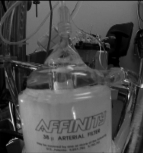
Figure 4.

Medtronic Affinity filter showing top-in bottom-out flow path.
DISCUSSION
The application of conventional screen filters, although commonly thought of as having a single purpose, can be further divided into the interconnected tasks of trapping, separating, and removing gas bubbles and debris. And while it is difficult to view each task in complete isolation, gross air-bolus injections were used to help visualize direction of the blood flow path through three different arterial-line filter designs and how it might affect the bubble-trapping function. Gross air bubbles tracking in the bottom-in bottom-out flow path of the prototype are seen rising rapidly in an arching spiral pattern, mostly reaching the purge port area before completing a single pass around the filter (16). This contrasts dramatically with bubble trapping observed in the top-in bottom-out flow path of the two commercial filters. Although the Affinity and D734 visually demonstrated excellent gross air purging capabilities, large bubbles are seen recirculating along the outer wall of both filters well below the level of their respective inlet and purge port areas (16).
While there are numerous distinguishing traits that set the three filters apart, the features most likely responsible for the observed differences in bubble trapping are the blood flow paths and inlet circumferences of the different filter housing bodies. This assertion is supported by the fact that the two commercial filters with downward flow paths and smaller inlet circumferences both displayed similar bubble trapping behaviors'. As buoyancy forces of bubbles entering the prototype filter appear to be aided by its rising flow pattern, the downward directed flow in both commercial filters is shown to be capable of pulling large bubbles deep into the filter housing proper (16). These observations might in fact be expected when taking into consideration the dominant effect that viscous drag has over buoyancy (17). Moreover, because the purge areas of both commercial filters are located immediately adjacent to their respective inlets, it is possible that there is insufficient time for complete deceleration of the incoming fluid to occur. This may in turn cause some bubbles to spill out of the purge area as they pass through the tight arch created by a smaller inlet circumference. In contrast, having the purge area located further away from the prototype's larger inlet circumference allows for a more complete deceleration of the incoming fluid. The distance from filter inlet to purge-port opening was taken to be approximately 21 cm for the prototype, 9 cm for the Affinity, and 7 cm for the D734.
Figures 2 and 4 show both the prototype and Affinity filters containing distinct vertical chambers above the inlet port that extend upward into the purge port opening, while a vertical rise in the housing above the level of its inlet port is barely visible in the D734 (Figure 3). As depicted in Figure 5 and the referenced video clip (16), gross air bubbles entering the upper section of the Affinity's purge area are quickly evacuated through its purge port, demonstrating again how rising flow imparts lift and augments buoyant forces with an increase in fluid velocity. This differs from the prototype and D734 filters, where the high inflow of gross air bubbles is seen accumulating just below their respective purge port openings (Figures 6 and 7). While the prototype demonstrated visually that it is well adept at handling gross air bolus injections (16), the internal volume of its purge port area is more than three times larger than the comparable section found in the Affinity filter (Table 1). Increasing velocity in the area just below the purge port opening of the prototype, by decreasing the internal volume in this section, should help further improve gross air clearance from the filter's upper most section. For the D734, improvements in gross air clearance from the purge port area might also be possible by incorporating similar features in its design to better coordinate the forces of flow, velocity, and buoyancy.
Figure 5.
Depicting rapid gross air bubble clearance through upper section of the Affinity filter's purge area.
Figure 6.

Arrow pointing to gross air bubble accumulation just below the prototype filter's purge port opening.
Figure 7.

Arrow pointing to gross air bubble accumulation just blow the D734 filter's purge port opening.
The shape of an arterial-line filter/bubble trap and its accompanying features has long been known to contribute to the effective removal of micro-bubbles in extracorporeal circuits (18). While empirically attributing any amount of effect to a single feature in isolation would be burdensome, the importance of the filter housing shape cannot be overstated as it determines its volume, flow path, rate of fluid deceleration, and the amount of filter screen that can be accommodated. A recent example demonstrating the significance of this can be taken from a study by Potger et al. which compared performance between an integrated and nonintegrated filter system (5). In a follow-up commentary to this work (19), the 38 μm nonintegrated filter was shown to have improved performance stability over the 25 μm integrated filter in terms of the percent increase in median bubble volume, count, and size emitted from each system as flow rate increased. Because rated pore-size cannot be used to explain the gain in performance stability, findings drawn from the Potger et al. study must highlight more the effects of the shape, volume, flow path, and amount of filter screen contained in the nonintegrated filter.
The present manuscript attempts to expand the language of arterial-line filter use by emphasizing the core functions of bubble trapping, separating, and removing. With a focus on the gross air-trapping role, this work draws attention to the importance of filter housing shape, and demonstrates how direction of the blood flow path can affect the application of these devices with implications for clinical operation. Using the blood flow direction as a means to better align the forces of buoyancy and viscous drag may offer a potential avenue for improved patient safety. If flow through both commercial samples was capable of pulling large air bubbles deep into the filter housing proper and in closer proximity to their respective outlets, it seems reasonable to expect that smaller less buoyant bubbles could also be affected in a similar if not more profound way, emphasizing sound reasoning behind any proposed need for improvement in arterial-line filter design.
REFERENCES
- 1.Herbst D. P., Najm H. K.. Development of a new arterial-line filter design using computational fluid dynamics analysis. J Extra Corpor Technol. 2012;44:140–5. [PMC free article] [PubMed] [Google Scholar]
- 2.Herbst D. P. The effects of pressure on gases in solution: Possible insights to improve microbubble filtration for extracorporeal circulation. J Extra Corpor Technol. 2013;45:94–106. [PMC free article] [PubMed] [Google Scholar]
- 3.Riley J. B. Arterial line filters ranked for gaseous micro-emboli separation performance: An in vitro study. J Extra Corpor Technol. 2008;40:21–6. [PMC free article] [PubMed] [Google Scholar]
- 4.Herbst D. P. Sequential blood filtration for extracorporeal circulation: Initial results from a proof-of-concept prototype. J Extra Corpor Technol. 2014;46:239–50. [PMC free article] [PubMed] [Google Scholar]
- 5.Potger K. C., McMillan D., Ambrose M.. Air transmission comparison of the Affinity fusion oxygenator with an integrated arterial filter to the Affinity NT oxygenator with a separate arterial filter. J Extra Corpor Technol. 2014;46:229–38. [PMC free article] [PubMed] [Google Scholar]
- 6.Yarham G., Mulholland J.. Pre-clinical laboratory evaluation of the new ‘AF’ arterial line filter range. Perfusion. 2010;25:267–76. [DOI] [PubMed] [Google Scholar]
- 7.Liu S., Newland R. F., Tully P. J., Tuble S. C., Baker R. A.. In vitro evaluation of gaseous microemboli handling of cardiopulmonary bypass circuits with and without integrated arterial line filters. J Extra Corpor Technol. 2011;43:107–14. [PMC free article] [PubMed] [Google Scholar]
- 8.Mueller X. M., Tevaearai H. T., Jegger D., Augstburger M., Burki M., von Segesser L. K.. Ex vivo testing of the Quart arterialx line filter. Perfusion. 1999;14:481–7. [DOI] [PubMed] [Google Scholar]
- 9.Jabur G. N. S., Wilcox T. W., Zahidani S. H., Sidhu K., Mitchell S. J.. Reduced embolic load during clinical cardiopulmonary bypass using a 20 micron arterial filter. Perfusion. 2014;29:219–25. [DOI] [PubMed] [Google Scholar]
- 10.Jones T. J., Deal D. D., Vernon J. C., Blackburn N., Stump D. A.. How effective are cardiopulmonary bypass circuits at removing gaseous microemboli? J Extra Corpor Technol. 2002;34:34–9. [PubMed] [Google Scholar]
- 11.Norman M. J., Sistino J. J., Acsell J. R.. The effectiveness of low-prime cardiopulmonary bypass circuits at removing gaseous emboli. J Extra Corpor Technol. 2004;36:336–42. [PubMed] [Google Scholar]
- 12.Willcox T. W., Mitchell S. J.. Microemboli in our bypass circuits: A contemporary audit. J Extra Corpor Technol. 2009;41:31–7. [PMC free article] [PubMed] [Google Scholar]
- 13.Burnside J., Gomez D., Preston T. J., Olshove V. F., Phillips A.. In-vitro quantification of gaseous microemboli in two extracorporeal life support circuits. J Extra Corpor Technol. 2011;43:123–9. [PMC free article] [PubMed] [Google Scholar]
- 14.Weitkemper H. H., Oppermann B., Spilker A., Knobl H. J., KÖrfer R.. Gaseous microemboli and the influence of microporous membrane oxygenators. J Extra Corpor Technol. 2005;37:256–64. [PMC free article] [PubMed] [Google Scholar]
- 15.Dickinson T. A., Riley J. B., Crowley J. C., Zabetakis P. M.. In vitro evaluation of the air separation ability of four cardiovascular manufacturer extracorporeal circuit designs. J Extra Corpor Technol. 2006;38:206–13. [PMC free article] [PubMed] [Google Scholar]
- 16.Herbst D. P. YouTube. Flow and buoyancy: Part three (video on the Internet). November 30, 2015. Available at: https://youtu.be/4BMm9RXJgfQ/. Accessed December 30, 2015 [Google Scholar]
- 17.Herbst D. P. Effects of purge-flow rate on microbubble capture in radial arterial-line filters. J Extra Corpor Technol. 2016;48:105–12. [PMC free article] [PubMed] [Google Scholar]
- 18.Galletti P. M., Brecher G. A.. Heart-Lung Bypass: Principles and Techniques of Extracorporeal Circulation. New York, NY: Grune & Stratton; 1962:154–159. [Google Scholar]
- 19.Herbst D. P. Working toward best practice: Microbubble filtration and patient safety during extracorporeal circulation. J Extra Corpor Technol. 2015;47:125–7. [PMC free article] [PubMed] [Google Scholar]