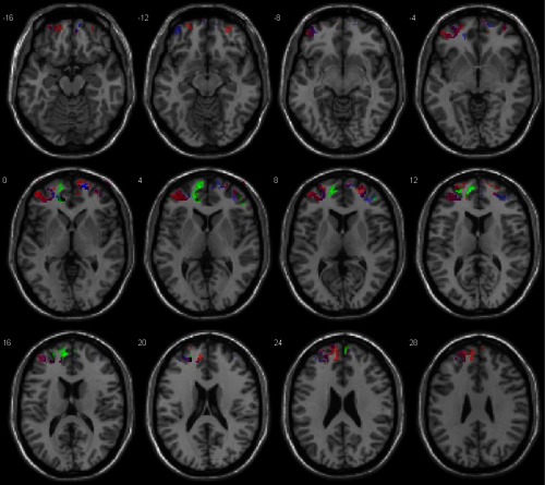
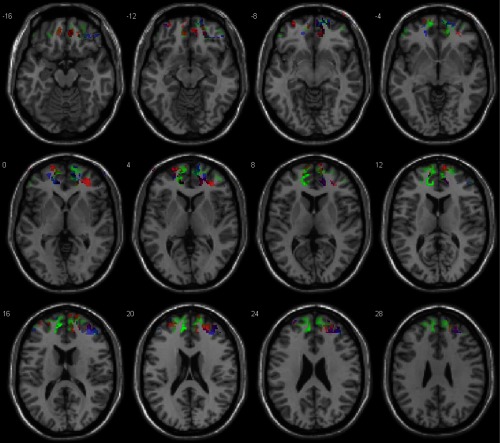
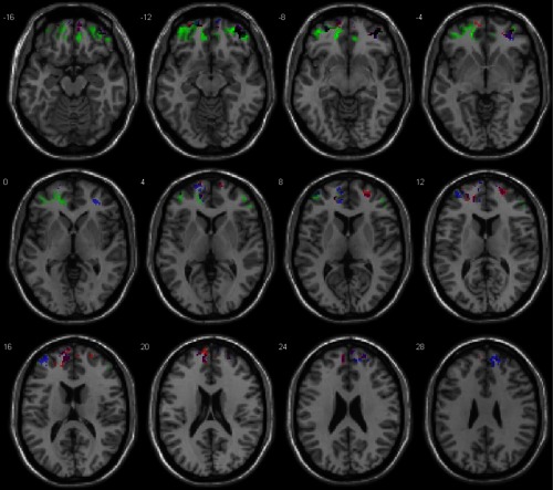
Abstract.
Diffuse optical tomography (DOT) measures concentration changes in both oxy- and deoxyhemoglobin providing three-dimensional images of local brain activations. A pilot study, which compares both DOT and functional magnetic resonance imaging (fMRI) volumes through t-maps given by canonical statistical parametric mapping (SPM) processing for both data modalities, is presented. The DOT series were processed using a method that is based on a Bayesian filter application on raw DOT data to remove physiological changes and minimum description length application index to select a number of singular values, which reduce the data dimensionality during image reconstruction and adaptation of DOT volume series to normalized standard space. Therefore, statistical analysis is performed with canonical SPM software in the same way as fMRI analysis is done, accepting DOT volumes as if they were fMRI volumes. The results show the reproducibility and ruggedness of the method to process DOT series on group analysis using cognitive paradigms on the prefrontal cortex. Difficulties such as the fact that scalp–brain distances vary between subjects or cerebral activations are difficult to reproduce due to strategies used by the subjects to solve arithmetic problems are considered. T-images given by fMRI and DOT volume series analyzed in SPM show that at the functional level, both DOT and fMRI measures detect the same areas, although DOT provides complementary information to fMRI signals about cerebral activity.
Keywords: diffuse optical tomography, functional magnetic resonance imaging, DRIFTER, statistical parametric mapping, group analysis, cognitive tasks
1. Introduction
Diffuse optical tomography (DOT) is a noninvasive imaging technique that uses near-infrared (NIR) light to image cerebral activations. DOT measures changes in the absorption of NIR light in the cerebral cortex, allowing an estimation of changes in cerebral oxygenated (HbO) and deoxygenated hemoglobin (HbR) concentration due to local brain activation.1 DOT uses at least two wavelengths in the range of 650 to (Ref. 2) travelling to and from the DOT device by optic fibers (optodes) or LEDs, to measure the absorbed quantity of NIR light from biological tissue by measuring diffusely scattered lights. The NIR light is applied to the subject’s head combined such as sources–detectors to form “optical data channels.” Changes in light attenuation between source and detector are transformed into changes in the concentration of HbO and HbR by applying the modified Beer–Lambert’s law.3
DOT transforms the detected light from different measuring distances on the surface into depth information providing three-dimensional images of cerebral activations, instead of the planar backprojection, which is obtained with the topographic approach.4 With the purpose of increasing spatial resolution and positional accuracy of optical brain imaging,5 two steps have been used to create functional DOT images. The first step is the forward model, which models light migration processes that quantitatively relates the activity inside the head tissue with the measured light intensity changes.6 The second step is an image reconstruction algorithm, which is used to reconstruct a three-dimensional activity image from light intensity changes measured from recordings on the head surface. There are different reconstruction methods, such as minimum norm estimates,7 linear constrained minimum variance,8 or source localization using spatial flexibility.9
Unlike DOT devices which measure HbO and HbR, functional magnetic resonance imaging (fMRI), which measures blood oxygen level-dependent (BOLD) response after a local neural activation, is rapidly becoming a “gold standard” for in vivo imaging of human brain activity due to its high spatial resolution, although it has some disadvantages, such as high sensitivity to participant motion, restrictive environment, low temporal resolution, and high cost.10
The hemodynamic changes measured by both DOT and fMRI devices are caused by dynamics in blood volume, blood flow, and blood oxygenation. Some physiological signals, such as heart rate or ventilation rate, involved in systemic blood oxygen and cerebral hemodynamics influencing the scalp layer11 may generate variability, which involves spatial and temporal changes throughout the brain and scalp12 during DOT neuroimaging experiments. In a previous research, a user-independent procedure consisting of a Bayesian algorithm13 on raw DOT data was applied to remove physiological noise caused by cardiac and breathing activity.
Hemodynamic changes during the performance of cognitive tasks such as arithmetic calculation can be measured in prefrontal areas using neuroimaging techniques,14–16 where cerebral activations are differential depending on the complexity of the arithmetical problems,17 the arithmetical ability of the subject,18 and strategies used to solve an arithmetical problem.19
However, there is no standard tool for the analysis of DOT data, which hinders the research groups’ ability to produce reproducible research. There are software programs to process topographic and tomographic data, which have been specifically created to process functional near-infrared spectroscopy (fNIRS) data. As the statistical parametric mapping (SPM) is a statistic tool, which has been widely used to process fMRI series, we propose here an approach to make DOT data suitable for analysis in SPM, without modifying SPM, accepting DOT volumes as if they were fMRI volumes, allowing a standard analysis of DOT series.
Accepting DOT volumes as if they were fMRI volumes, canonical SPM20 was applied during the processing of DOT data as a statistical tool in the same way as fMRI. In order to apply canonical SPM as a statistical tool, one assumes which image reconstruction methods using commercial NAVI (NIRx Medical Technology LLC, Glen Head, New York) software are valid, but unlike other authors, a minimum description length (MDL)21 index was applied to select those singular values, which reduce the dimensionality of the data, according to image reconstruction algorithm used. Furthermore, DOT volumes with normalized standard space Montreal Neurological Institute (MNI) are adapted. These procedures enable a robust and user-independent analysis of DOT series making them suitable for statistical analysis in SPM in the same way as fMRI series are.
The aim of this work is to demonstrate that the above procedures for the DOT data analysis are applicable to group analysis using a cognitive paradigm on the frontal cortex. Brain activations in the frontal cortex are more subtle during motor or visual tasks.22 The scalp–brain distance in the prefrontal cortex varies across subjects, and this may reduce the quality of the DOT signal from the cerebral cortex during the recordings, because the penetration depth of NIR light in adult human brain imaging is about 3 to 4 cm.23 It is possible, using the above procedures, to compare t-contrast maps given by SPM for both DOT and fMRI modalities.
2. Methods
2.1. Subjects and Stimulus Procedure
Twenty four healthy right-handed volunteers were divided into two study groups of 12 volunteers in each group according to arithmetical abilities. One group was formed of undergraduate science students (engineering, physics, or mathematics), who require a high level of mathematical ability and the other group was formed of undergraduate arts and social science students (philosophy or psychology), who do not need a high level of mathematical skill. All subjects who participated in the study had no history of neurological disease. Written informed consent was explained and signed prior to experiment. The study was approved by the local ethics committee (Universidad de La Laguna) and was conducted in accordance with the Declaration of Helsinki.
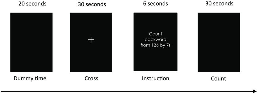
A block design was developed in which the participants began with 20 s of dummy time to stabilize the photon absorption and to ensure tissue steady-state magnetization in fMRI. The rest period consisted of the observation a static white cross in the center of the screen. The instruction, e.g., “count backward from 136 in sevens” in the mother-tongue of the participant (Spanish) appeared 6 s before the block of tasks, which started when the statement disappeared. The calculation condition (difficult count) involved the participants starting to count backward from a three-digit integer in, e.g., sevens, nines, or thirteens until the end of the task period. The control condition (easy count) involved the subjects counting backward from a three-digit integer in, e.g., ones or twos, at their own speed. A different three-digit integer and subtraction number were given at the beginning of each 30-s period while the screen was black, as shown in Fig. 1.
Fig. 1.
Scheme of the block design with the time onset of each condition. A total of 12 blocks included easy and difficult count were conducted in fMRI and DOT devices. The upper row indicates the time of each block. The lower row indicates each condition.
A total of twelve blocks of tasks, divided into six blocks for calculation condition and six blocks for control condition, were performed in both DOT and fMRI devices with a random order of the instructions. The paradigm was displayed on the screen using Presentation (Neurobehavioral Systems, Inc., Albany, California).
As fMRI has been the most commonly used technique in neuroimaging studies, the assumption was made that information provided by fMRI was reliable. A comparison between active condition (difficult count) and control condition (easy count) indicated frontal areas, which involve mental calculation in fMRI, as shown in Table 1.
Table 1.
Representative number of voxels by anatomical area in fMRI according to complexity cognitive tasks.
| Anatomical area | Number of voxels, difficult > easy count | Number of voxels, easy > difficult count |
|---|---|---|
| Difficult > easy count BOLD signal | T: 1.64, ; corrected FDR | T:1.64, ; corrected FDR |
| Frontal superior medial left | 186 | 11 |
| Frontal superior medial right | 38 | 21 |
| Frontal superior left | 7 | 54 |
| Frontal superior right | 54 | 12 |
| Cingulum anterior left | 11 | — |
The different levels of task complexity were reflected in the fMRI data for a subject without arithmetic skills. Solving the problems of a greater (as compared to lesser complexity) complexity was accompanied by a stronger and more widespread brain activation comprising a frontal cortex. T-contrast maps of fMRI helped to corroborate the implication of prefrontal areas in the paradigm applied allowing the comparison of t-contrast maps given by SPM for both fMRI and DOT modalities.
The subjects performed the task in similar conditions for the DOT and fMRI measurements: supine position, dark room, compatible fMRI glasses (VisuaStim Digital-Resonance Technology Inc.), where the paradigm was displayed on the screen, physiological sensors, and a grip on the right hand, which allow us to confirm whether the participants performed the task properly according to the frequency of pressing the button for each level of complexity because the count was performed in silence. The order of each session was counterbalanced between the subjects starting with DOT or fMRI measurements.
After the DOT and fMRI measures, each subject was asked which strategies they used to solve the calculation. Mental calculation is a complex task involving several fundamental cognitive activities including covert production of numbers, retrieving arithmetic facts from memorized tables, execution of specific calculation procedures such as subtraction, and storing data in working memory for further operations.19 The fact that subtraction is not an automatic procedure, which may require specific calculation strategies, explains the high level of prefrontal activation observed during this cognitive activity.
2.2. Optical Data Acquisition
A DYNOT 232 instrument (NIRx Medizintechnik GmbH Berlin, Germany) was used to acquire the DOT data. The system performs continuous-wave measurements using two frequency-encoded laser sources at 760 and 830 nm with a sampling rate of 1.8 Hz in a time multiplexed scanning fashion. The equipment provides a high dynamic measurement range needed for diffuse tomography multidistance measurements. NIR light travelled to and from the DOT device by optic fibers. In the present study, 64 fiber optic probes were used, which acted as detectors and 32 of them acted as a source, thereby providing 2048 optical channels. The optodes were arranged in a rectangular grid of and with a distance of 1 cm between them.
The instrument’s moldable scaffolding allows the placing of the fibers on the head to make a more stable optical contact to the skin, thereby minimizing artifacts from mechanical noise. The grid was placed over the prefrontal cortex above the zygomatic arch until Fz position referring to the EEG 10-20 system.24
2.3. Data Quality
The optical signals propagating through the brain contain several spontaneous fluctuations originating from cardiac pulsation, respiration, and change of blood pressure,25 which contaminate the signals measured by DOT and induce spatial and temporal changes able to give a false interpretation of brain activations.
The subjects were monitored through physiological records throughout the experimental period. Each of them wore sensors to measure cardiac cycle and breathing. Physiological data were recorded continuously at 4 KHz using AD Instrument ML870/P PowerLab16/30 as measurement system.
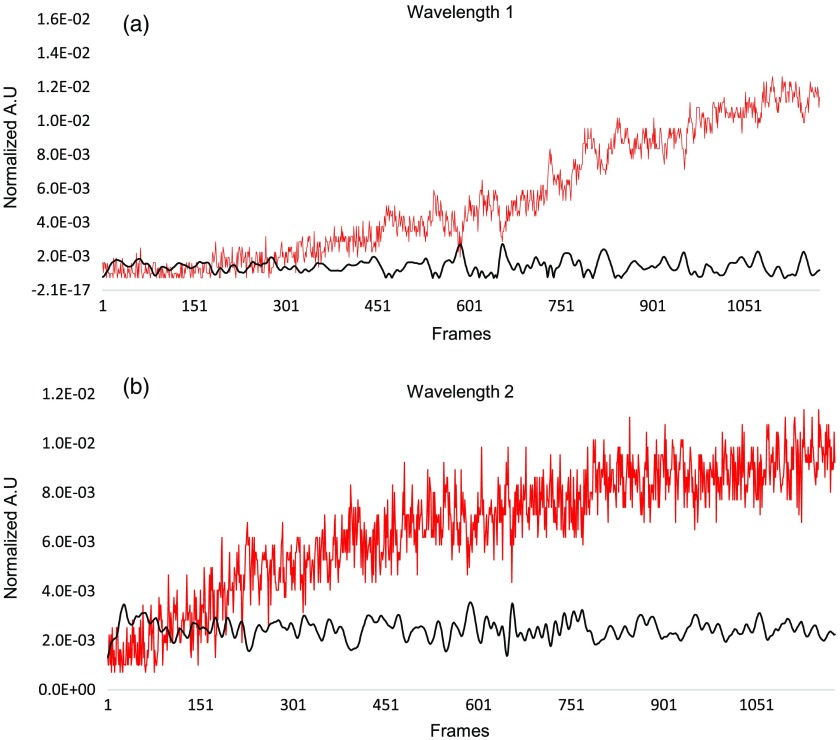
The dynamic retrospective filtering of physiological noise (DRIFTER) algorithm,13 which modeled and removed physiological data that were recorded during experimental time in each subject, was used to filter raw DOT data, allowing accurate dynamical tracking of the variations in the cardiac and respiratory frequencies (Fig. 2). Thus, a false interpretation of brain activations generated by contaminated signals is avoided and serial correlations are reduced allowing the application of canonical regression models used by SPM.
Fig. 2.
Representation of average optical channels (2048) over time of a subject. (a) and (b) Red plot shows raw DOT data without filtering and black plot shows DOT data DRIFTER-filtered algorithm for both wavelengths. Abscissas axes represent the experimental time in frames and ordinate axis correspond to normalized arbitrary units.
2.4. Coregistration of Optodes Position
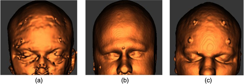
Prior to the experiment, the grid of optodes was positioned on each subject to mark the four corners of the grid array used. The corners were marked by vitamin E capsules, which provide a contrast in T1 images.
The use of a finite-element mesh (FEM) precalculated over a generic head model requires a spatial normalization tool of SPM8 (The Wellcome Trust Centre for Neuroimaging, University College London). The mentioned SPM tool computes an affine and a nonlinear transformation between two volumes to warp both images and fit them into a template. The generic head model was defined as the template and the subject’s anatomical scans were defined as the source image. Therefore, the subject’s anatomical scans were warped to fit the boundaries of the generic head model without losing structural information.26 The above transformations allow the translocation of the subject’s anatomy to the anatomic MR scans of the generic head model on which the FEM is based. The position of 64 optical fibers was interpolated between the coordinates of the four corners marked by vitamin E and assigned to the FEM (Fig. 3).
Fig. 3.
Representation of the four corners, which marked the position of the optical fibers for coregistration. (a) Subject’s anatomical scans with the fiduciary marks on the head surface in real space. (b) Anatomical MR scans of the generic head model on which the FEM is based. (c) Subject’s anatomical scans warped into the space of the generic head model.
2.5. Forward Model and Image Reconstruction
Image reconstruction requires the creation of a weight matrix containing information on each DOT voxel of signals collected from all source–detector combinations on the surface of the medium.27 Assuming as valid procedure to reconstruct the DOT image, NAVI tools were used.
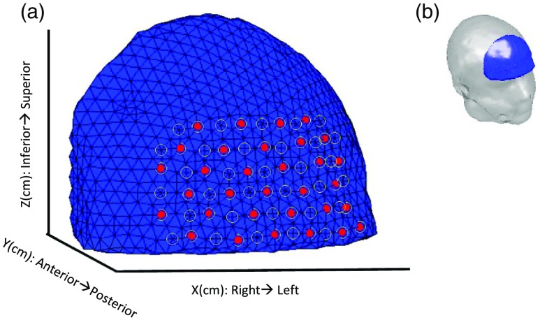
The BrainModeler tool from the NIRx NAVI imaging was used, which contains FEMs,6 which describe an inhomogeneous distribution of optical properties and an arbitrary geometry of different layers. The location of source and detectors on the tissue surface and inner optical properties is defined as the forward model. The forward model describes changes in measured boundary data that are caused by small changes of absorption within the tissue for each channel-node combination. The submesh that best approximated the area of our measurements according to the translocate positions of the fibers grid was selected. The submesh contained 4921 nodes and 21,144 tetrahedrons and thus, its dimensions were , as shown in Fig. 4.
Fig. 4.
Finite model element mesh selection. (a) Localizations of optical fibers (circles) on the boundary were defined. Red dots correspond to source and all of them act as receptors. (b) Atlas with an FEM (blue) on the prefrontal cortex.
A weight matrix () is obtained as result of the relationship between the number of nodes of the submesh (4921) and optical channels (2048) measured by the combination of 32 sources–64 detectors located on the head surface:
where is the vector containing the measures for all source–detector combinations and is the vector containing optical properties. Therefore, small changes in lead to proportional changes in by using a linear perturbation approach.
A normalized difference method28 was applied to reconstruct DOT images. The above method relates, according to a perturbation approach, measured surface data with changes in interior optical properties of the medium used, compared to a reference medium. Absorption changes at two wavelengths led to reconstructed images of relative changes in HbO, HbR, and HbT using extinction coefficients of HbO and HbR for both wavelengths.29
DOT signals were scaled by the normalization of column vector to their mean values and an offset of 2.1014 was applied to the DOT values so that they oscillated on the same scale as fMRI values.
The rebuilding of the DOT image requires inverting the weight matrix resulting in an underdetermined and ill-posed problem formulated as an inverse problem, due to the fact that NIR light is highly attenuated with an increasing depth.
NIRx NAVI inverts the weight matrix using the truncated singular value decomposition method. The MDL criterion was used as the index to select the number of singular values in order to reduce the dimensionality of . DOT images were reconstructed to a dimension of from the FEM library, by default. The values of the nodes of FEM from this default dimension are interpolated to obtain other dimensions, such as .
Finally, 1465 DOT volumes per experiment with a size of voxels were reconstructed, in Analyze format, which is compatible with SPM, for each molecule HbO and HbR. The acquisition of all functional volumes was checked with a repetition time of .
2.6. Normalized Anatomical Space
Once reconstructed, DOT volumes for each hemoglobin molecule of HbO and HbR were fitted into a normalized anatomical space (MNI) using the spatial normalization tool of SPM8.
2.7. Statistics
T-contrast maps were calculated in SPM8 for both data modalities to determinate the degree of complementarity between the fMRI-BOLD signal and hemodynamic changes registered by the DOT device.
The DOT images were filtered to improve the signal-to-noise ratio, using a high pass filter based on a discrete cosine transform, 128-s cut-off period. The design matrix consisted of three regressors with onsets for rest blocks and onsets for mental count blocks according to the level of complexity. The regressors were convolved with the canonical hemodynamic response function (HRF). Polarities of the canonical HRF functions were reversed to visualize negative response.30 After estimation, activation maps were generated for the subjects by applying a fixed effects model analysis. Three contrasts were computed: , , and .
2.8. Functional Magnetic Resonance Imaging Data Acquisition
fMRIs were acquired in the volunteers by applying the same stimulation pattern used in the DOT experiment. The experiment was performed in a 3T Signa Excite HD scanner (General Electric). T1-weighted volume was acquired to precise anatomical localization (, , flip , , in plane resolution, spacing between , , ). The anatomical slices covered the whole brain and were acquired parallel to the anterior–posterior commissure. A sequence of 415 T2*-weighted spiral volumes was acquired, 15 axial slices each, field of view is 256 mm, slice thickness is 4 mm, interslice gap is 1 mm, matrix of voxels, flip angle is 77 deg, TR is 2000 ms, and TE is 24 ms.
2.9. Preprocessing and Statistical Analyses in Functional Magnetic Resonance Imaging
fMRI volumes were preprocessed in SPM8 by applying realignment to correct motion artifacts, slice timing correction, coregistration with structural image (T1), and fit into standard anatomical space (MNI). An isotropic smoothing kernel of 8-mm full-width half-maximum was applied to the spiral images to suppress noise and effects due to residual differences in functional and gyral anatomy and high-pass filter with 128-s cut-off period to remove low frequency noise corresponding to breathing and pulse.
A general linear model (GLM) was constructed in SPM8 for the task. The design matrix consisted of three regressors with onsets for rest blocks and onsets for mental count blocks according to the level of complexity. The regressors were convolved with the canonical HRF. After estimation, a fixed effects model analysis was performed to generate t-contrast images comparing difficult count > easy count, difficult count > rest and easy count > rest. Fixed model analysis does not allow for any overall conclusions for the population, but it does for this sample. This fact is secondary because our goal is to compare both neuroimaging techniques.
2.10. Region of Interest Analysis
There are studies that report that parietal–temporal and frontal networks are involved during calculation processing.14 Our interest was to only study frontal areas implicated in mental count with the aim of determining whether the processed method for DOT data applied to group analysis is valid, using fMRI data as the “golden standard.” Thus, only the frontal area according to the submesh selected for DOT was represented here. The multidistance approach used by DOT allows the detection of changes in both extracerebral and cerebral areas. As our interest was only cerebral areas, extracerebral areas were masked.
3. Results
3.1. Behavior Analysis
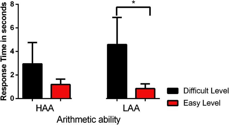
The frequency of pressing the button for each level of complexity was analyzed to confirm whether the participants performed the task properly, which allowed the quantification of response time during the subtractions in each block of tasks. Figure 5 shows a longer response time during the subtractions in the difficult level than easy level for each group [high arithmetic ability (HAA) and low arithmetic ability (LAA)]. These results are to be expected since, e.g., the response times are lower for subtraction in ones than for subtraction in sevens. Furthermore, there are significant differences () between the easy and difficult level in LAA group according to Tukey’s multiple comparisons.
Fig. 5.
Representation of response time in seconds during the subtraction performed by a subject for each HAA and LAA group during a session of mental count. Abscissas axes show difficult level (black bars) and easy level (red bars) for each group, and the ordinate axis shows the averages and errors of time in seconds in each count. There are significant differences *() between difficult and easy complexity’s level in LAA group.
3.2. Imaging Results
The use of different strategies by each subject makes it difficult to reproduce an experiment, where mental calculations are involved. Fact that is not important in this work, because our aim is to compare both imaging techniques.
Poststudy, each subject was asked which strategies they used to solve the calculation. Therefore, we separated the two aforementioned groups (HAA and LAA) into three subgroups, each with four subjects according to strategies used during mental calculation according to fMRI data (Table 2).
Table 2.
Classification in subgroups according to strategies of subtraction.
| Subgroups of HAA | |
| HAAa | Applied algorithm to approximate to numbers interval (approximate numbers system). |
| HAAs | Applied direct subtraction and visualized the numbers as a counter. |
| HAAm | Combined both aforementioned strategies according to complexity of task (difficult as HAAa, easy as HAAs). |
| Subgroups of LAA | |
| LAAf | Applied mental finger counting. |
| LAAr | Recalled the last two digits and subtracted one by one. |
| LAAm | Combined both aforementioned strategies according to complexity of task (difficult as LAAf, easy as LAAr). |
Three t-contrasts in SPM8 were computed but only one t-contrast was selected (difficult count > easy count) because this is the best representation of cognitive changes per se unlike the other contrasts (difficult count > rest or easy count > rest). T-contrast maps were obtained by SPM8 and displayed using xjView 8.131 for both the DOT series and fMRI series. T-images were mapped onto MNI space in axial view for each HbO, HbR, and BOLD signal ().
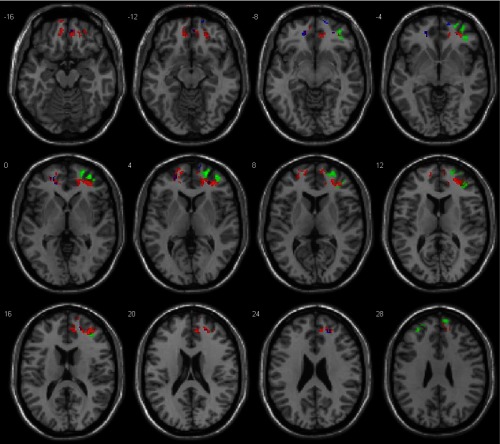
Figure 6 shows t-maps of activation for contrast difficult > easy count measured by DOT and fMRI corresponding to the HAAa subgroup. T-maps show prefrontal bilateral activations, focused on the right hemisphere for HbO and BOLD signals. Both HbO and HbR have a similar distribution in MNI space.
Fig. 6.
T-maps of brain activation for the HAAa subgroup measured by DOT and fMRI. All results were mapped onto MNI space. Threshold corrected FDR, at the voxel level for HbO (red), HbR (blue), and BOLD (green) signals. Note color change to violet in common voxels.
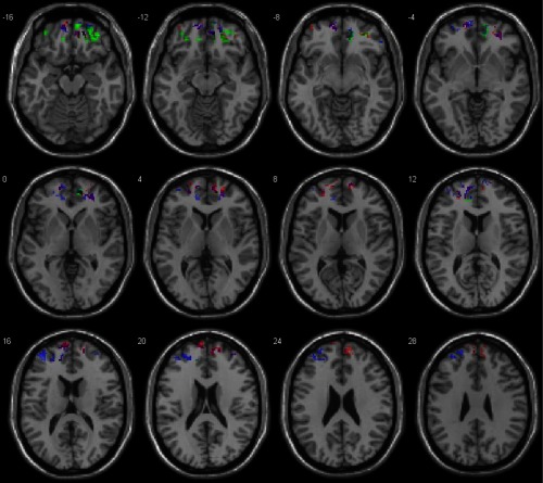
Figure 7 shows t-maps of activation for contrast difficult > easy count measured by DOT and fMRI corresponding to the HAAs subgroup. T-maps show bilateral activations on more orbital areas for BOLD signals while HbR and HbO show bilateral activation on superior frontal area, where HbR appears on left hemisphere predominantly.
Fig. 7.
T-maps of brain activation for the HAAs subgroup measured by DOT and fMRI. All results were mapped onto MNI space. Threshold , corrected FDR at the voxel level for HbO (red), HbR (blue), and BOLD (green) signals. Note color change to violet in common voxels.
Figure 8 shows t-maps of activation for contrast difficult > easy count measured by DOT and fMRI corresponding to the HAAm subgroup. T-maps show bilateral activation for HbO and HbR throughout the measurement space while BOLD only deals with left orbital area.
Fig. 8.
T-maps of brain activation for the subgroup HAAm measured by DOT and fMRI. All results were mapped onto MNI space. Threshold uncorrected for HbO (red), HbR (blue), and BOLD (green) signals. Note color change to violet in common voxels.
Figure 9 shows t-maps of activation for contrast difficult > easy count measured by DOT and fMRI corresponding to the LAAf subgroup. T-maps show frontal bilateral activations for HbR, HbO, and BOLD signal, although BOLD and HbO signals are more representative in the left hemisphere than the right hemisphere. BOLD does not include orbital areas as in previous cases.
Fig. 9.
T-maps of brain activation for the LAAf subgroup measured by DOT and fMRI. All results were mapped onto MNI space. Threshold , corrected FDR at the voxel level for HbO (red), HbR (blue), and BOLD (green) signals. Note color change to violet in common voxels.
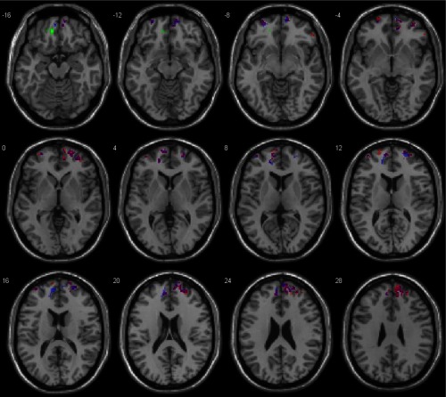
Figure 10 shows t-maps of activation for contrast difficult > easy count measured by DOT and fMRI corresponding to the LAAr subgroup. T-maps represent bilateral activations focused on more frontal areas, near the interhemispheric fissure for HbO, HbR, and BOLD signals.
Fig. 10.
T-maps of brain activation for the LAAr subgroup measured by DOT and fMRI. All results were mapped onto MNI space. Threshold corrected FDR, at the voxel level for HbO (red), HbR (blue), and BOLD (green) signals. Note color change to violet in common voxels.
Figure 11 shows t-maps of activation for contrast difficult > easy count measured by DOT and fMRI corresponding to the LAAm subgroup. T-maps show the predominance of the BOLD signal in bilateral orbital areas. Both HbO and HbR signals appear to have the same distribution as the BOLD signal, where some voxels of HbR do not match with the other molecules.
Fig. 11.
T-maps of brain activation for the LAAm subgroup measured by DOT and fMRI. All results were mapped onto MNI space. Threshold corrected FDR, at the voxel level for HbO (red), HbR (blue), and BOLD (green) signals. Note color change to violet in common voxels.
All subgroups show bilateral activations in the prefrontal cortex with a dominance of the high arithmetic ability subgroups in the right hemisphere while subgroups belonging to the low arithmetic ability group dominate in the left hemisphere. However, each subgroup has different cerebral activation loci according to strategies used to solve the mental calculation. These differences between subgroups make it difficult to determine which common cerebral areas were activated for each molecule, so DOT and fMRI were analyzed spatially to test the complementarity level between measured signals and to determine which functional areas matched. Table 3 shows the common number of voxels between each DOT and fMRI series.
Table 3.
Representation of number of voxels common by anatomical area to each combination between HbO-BOLD and HbR-BOLD.
| Anatomical region | Peak MNI co-ordinate |
No. of voxels | ||
|---|---|---|---|---|
| Subgroup HAAa | ||||
| Difficult > easy count (T: 2.35, ) | ||||
| Middle frontal gyrus | 34 | 42 | 9 | |
| Frontal superior right | 26 | 46 | 12 | 10 |
| Difficult > easycount (T: 2.35, ) | ||||
| Frontal medial orbital right | 38 | 44 | 244 | |
| Cingulum anterior right | 16 | 46 | 10 | 11 |
| Frontal superior medial right |
12 |
60 |
26 |
12 |
| Subgroup HAAs | ||||
| Difficult > easy count (T: 1.65, ) | ||||
| Middle frontal gyrus | 32 | 46 | 9 | |
| Frontal middle orbital right | 20 | 46 | 142 | |
| Cingulum anterior left | 44 | 14 | 6 | |
| Difficult > easy count (T: 1.65, ) | ||||
| Frontal medial orbital right | 20 | 46 | 93 | |
| Rectus right | 12 | 42 | 42 | |
| Frontal superior medial right |
14 |
48 |
0 |
26 |
| Subgroup HAAm | ||||
| Not presented common voxels | ||||
| Subgroup LAAf | ||||
| Difficult > easy count (T: 1.65, ) | ||||
| Frontal medial orbital right | 12 | 54 | 110 | |
| Cingulum anterior left | 44 | 0 | 17 | |
| Cingulum anterior right | 12 | 44 | 8 | 10 |
| Frontal middle right | 48 | 40 | 16 | 25 |
| Difficult > easy count (T: 1.65, ) | ||||
| Frontal medial orbital left | 42 | 9 | ||
| Frontal medial orbital right | 12 | 54 | 27 | |
| Frontal superior medial right | 20 | 42 | 0 | 11 |
| Cingulum anterior left | 44 | 0 | 21 | |
| Frontal superior medial left | 58 | 0 | 34 | |
| Cingulum anterior right | 12 | 44 | 8 | 14 |
| Frontal superior medial right | 12 | 60 | 8 | 40 |
| Subgroup LAAr | ||||
| Difficult > easy count (T: 3.1, ) | ||||
| Frontal medial orbital right | 12 | 54 | 110 | |
| Cingulum anterior left | 44 | 0 | 17 | |
| Cingulum anterior right | 12 | 44 | 8 | 10 |
| Frontal middle right | 48 | 40 | 16 | 25 |
| Difficult > easy count (T: 3.1, ) | ||||
| Frontal middle orbital right | 42 | 48 | 124 | |
| Frontal superior orbital left | 60 | 14 | ||
| Frontal middle orbital left | 58 | 23 | ||
| Cingulum anterior left |
|
50 |
2 |
10 |
| Subgroup LAAm | ||||
| Difficult > easy count (T: 3.1, ) | ||||
| Frontal middle orbital right | 42 | 48 | 126 | |
| Frontal superior orbital left | 60 | 16 | ||
| Frontal middle orbital left | 54 | 21 | ||
| Cingulum anterior left | 50 | 2 | 10 | |
| Frontal middle left | 56 | 4 | 20 | |
| Difficult > easy count (T: 3.1, ) | ||||
| Middle frontal gyrus | 46 | 9 | ||
| Frontal middle right | 46 | 46 | 4 | 11 |
| Frontal superior left | 54 | 10 | 33 | |
| Frontal superior medial left | 48 | 12 | 14 | |
| Frontal superior medial right | 8 | 60 | 22 | 12 |
The results show common anatomical regions between each hemoglobin molecule (HbO and HbR) and BOLD signal measured by DOT and fMRI equipment, respectively. From a global point of view, conjunction analysis shows that, in the prefrontal cortex, DOT detects the same areas as fMRI at the functional level. But in performing conjunction analysis, we lost information because both techniques separately provide more information about hemodynamic changes.
4. Discussion
4.1. Prefrontal Activation During Arithmetic Calculation
Different brain regions are responsible for the different functions executed during arithmetic problem solving. Studies of neuroimaging indicate the role of the parietal cortex in the calculating and processing of numbers and of the frontal cortex in numerical knowledge and working memory.32 The interest of the present study was to observe the frontal lobule with a cognitive paradigm based on subtraction (difficult > easy), and the global results show activations in the bilateral superior frontal gyrus, inferior and middle frontal left, bilateral frontal inferior, and cingulum anterior. These areas were found by other authors during addition and subtraction operations in adults,33 and even in children with learning disability affecting the normal acquisition of arithmetic skills.34
However, each subgroup shows different activation loci according to strategies used as in the case of subgroups with high arithmetic abilities, where HAAa and HAAs show dominance in the right hemisphere. This dominance may be explained by the approximate numbers system, which represents numerical magnitude information in a language independent analog fashion and implicates frontal and parietal circuits in the right hemisphere.35 But, the HAAm subgroup shows slow activations (, uncorrected) for both DOT and fMRI measurements, which may be due to a combination of strategies used, not shown a specific activation.
Otherwise, the subgroups with low arithmetic abilities show dominance in the left hemisphere, which increased with task difficulty, a complex task can therefore be expected to produce a greater number of activated voxels in the left compared to the right hemisphere36,37 or in the cases of both subgroups, LAAf and LAAm, that applied mental finger counting, which are habits related to hemispheric lateralization,38 which displayed the preferential involvement of the left prefrontal cortex although the subjects were right-handed. The LAAr subgroup also showed more dominance in the left hemisphere, because its role in the planning of elementary sequences needed to execute a calculation procedure.39 In this case, the strategy used showed activations in orbital areas that may be involved in the rapid learning of visual associations40 and the frontal medial area, which supports the demand of working memory during arithmetic operations.41
The acquisition of arithmetical skill to resolve a mental calculation of the HAA group was reflected in the results, which showed weaker brain activations than the LAA group. The academic formation of each group may be involved in the acquisition of arithmetical abilities; therefore, this leads one to think that it would be difficult for one group to acquire the same strategies of another group.
4.2. Image Quality
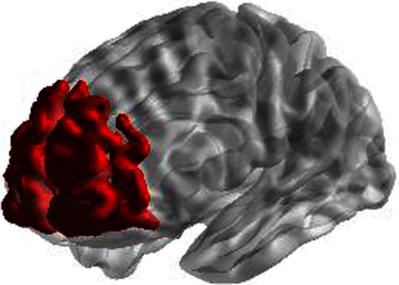
The signals in previous fMRI and NIRS studies are highly correlated between both modalities.42 The present work demonstrates that DOT activations are functionally similar to fMRI activations in the prefrontal cortex. However, the percentage of volume overlap between DOT and fMRI voxels was calculated in a defined space of 6384 voxels with a size of for each voxel. This space corresponds to the frontal area defined by the submesh of the FEM library selected in this study without extracerebral areas fitted onto normalized MNI space (Fig. 12), besides which, the percentage was calculated according to significant voxels represented by t-maps of fMRI for each subgroup. The percentage of common voxels between HbO-BOLD and HbR-BOLD for each subgroup is shown in Table 4.
Fig. 12.
Representation of the space defined by submesh selected from FEM library, without extracerebral areas.
Table 4.
Percentage of common voxels in the overlap between DOT and fMRI.
| No. of voxels for each subgroup | Within space defined by submesh | By t-maps of fMRI | |||||
|---|---|---|---|---|---|---|---|
| Subgroup | HbR-BOLD | HbO-BOLD | % Voxels HbR-BOLD | % Voxels HbO-BOLD | % Voxels Total | % Voxels HbR-BOLD | % Voxels HbO-BOLD |
| HAAa | 19 | 267 | 0.29% | 4.18% | 4.48% | 5% | 43% |
| HAAs | 157 | 161 | 2.45% | 2.52% | 4.97% | 59% | 57% |
| LAAf | 162 | 156 | 2.53% | 2.44% | 4.98% | 8.92% | 8.93% |
| LAAr | 162 | 171 | 2.53% | 2.67% | 5.21% | 20% | 27.7% |
| LAAm | 193 | 79 | 3.02% | 1.24% | 4.26% | 17% | 15% |
DOT volumes are treated as fMRI volumes, thereby t-contrast images have been used as the metric to quantify the percentage of common voxels between both modalities by a conjunction analysis, which allows testing for common activation across subjects or tasks creating the intersection of statistical maps thresholded at an alpha rate of 0.05 from random field theory.43
A low percentage of voxels is shown in the overlap between modalities for each subgroup, which is, perhaps, because the use of FE mesh is not personalized. The use of a generic head model for the forward light modeling, making it necessary to coregister subject-specific MR anatomy with head model MR anatomy to localize the position of optodes. This procedure could reduce the spatial accuracy of the derived activation foci, because there are variabilities in the brain structures and the thickness of the extracerebral tissue.44 The measured activation patterns can only be projected onto structural MRI, which is performed on the individual subject, when external landmarks are required for cranio–cerebral correlations with the electrode placement system.45 An approach would be to create a finite element for a standard brain template46–48 or subject-specific MR scans,49,50 which forward model considering different optical properties for each brain layer, which could minimize the reconstruction errors and improve spatial accuracy.
However, the use of a precalculated generic FEM allows a saving in time and energy compared to the generation of individual FE-meshes and forward models, especially for studies comprising many subjects and using high density grids.51
Normalization onto MNI space leads one to think that there could be another factor to explain the results of the overlap between both modalities. Spatial normalization was developed for voxel-based analysis in activation brain studies. This procedure takes into account a complete specification of the spatial topography of each image, e.g., the topography of an image can be characterized in terms of the coefficients corresponding to the spatial basis functions. This coefficient, taken in conjunction with the reference image, is a complete specification of the topography of the original image. The anatomical topography can be characterized by multivariate measures and depends on conventional multivariate statistics.52 Therefore, normalization procedures for DOT image onto MNI space should not distort or increase variation in the GLM analysis.
Previous studies have measured qualitatively and quantitatively the colocalization between DOT and fMRI in visual53 and motor44 areas. FEM specific to each layer of a subject MR anatomy guarantees an alignment with fMRI data allowing the calculation of localization error in each voxel using, e.g., an average center-of-mass or phase map.54 The calculation of localization error in each voxel on frontal areas could help to explain the discrepancies observed in the overlap between both modalities.
4.3. Use of Canonical Statistical Parametric Mapping
On the one hand, in fMRI studies, the probability of obtaining one or more activation foci of at least one voxel, is small, e.g., -value . Gaussian processes allow a significant advance in detecting activation foci in SPM, so information about the spatial extent or volume of the activation is included in the analysis of significant focal change.55 In DOT studies, the probability of obtaining activation foci is high at the same -value. DOT volumes obtained with the approach in the present study are sufficiently robust to be estimated giving significant activation foci without applying a Gaussian kernel, unlike NIRS-SPM,56 which applies a different noise treatment in fNIRS and fMRI.
During preprocessing, fMRI data were smoothened with a Gaussian kernel of 8 mm typically used to match with DOT data. An alternative approach would be the use of 13-mm Gaussian smoothing for fMRI, the use of 8-mm Gaussian smoothing for DOT data, or the use of both. These approaches would increase the number of common voxels in the overlap between both DOT and fMRI t-images.
On the other hand, SPM applies one process to analyze each voxel using any statistical parametric test. The resulting statistics are assembled into an image, that is then interpreted as a spatially extended statistical process.57 The present work allows a GLM analysis voxel-by-voxel over reconstructed DOT images for each molecule HbO and HbR to be made, unlike other authors who applied GLM analysis prior to the reconstruction of the images.46,48
4.4. Limitations of Study
Studies have tried to find a spatial and temporal correlation between the BOLD signal and HbR and HbO signal measurement by both imaging techniques.42 The activations in the prefrontal cortex recorded after cognitive tasks generated more subtle activation changes unlike motor58 or visual59 tasks. There was no repeated activation pattern during the cognitive paradigm in the cases here, making the study difficult to reproduce and which would require a larger sample size than the one used here. Besides, simultaneously, recordings must be made to compare both modalities60 while the cognitive paradigm is presented to the subject.
From the methodological point of view, there are some considerations, such as the physical principles of photon transport in scattering media restrict the precision of the reconstruction. Assumptions of optical properties in the subject limit the precision.44 Localization of optode fibers over each individual’s head prior to generating the FE mesh, which saves in time and makes group analysis difficult, could also introduce localization errors due to transformation procedures. Besides, the FE mesh precomputed on a generic head does not take into account that the thickness of the extracerebral tissue varies between subjects, which reduces the spatial accuracy of activated foci. NIR light only penetrates 3 to 4 cm deep, another limitation that should not be forgotten.
4.5. Neurovascular Coupling
Hemodynamic molecules measured by DOT provide complementary information to fMRI measurements. When spatially comparing t-maps obtained by DOT and fMRI measures, both HbO and HbR show common voxels with BOLD signals, but if they are analyzed separately, it may appear that HbO and BOLD are in greater concentration and better spatial match than HbR.60 Vasodilatation generated by neural activation is reflected in HbO and BOLD signals, whereas in some cases with HbR, this even appears in the contralateral hemisphere. One possible explanation is that HbR increased during neural activation and was then washed by oxygenated blood arriving from vasodilatation.61 These increased HbR, which have not been washed because nearby cerebral areas demand oxygen, may be detected by DOT. Therefore, DOT provides most information about hemodynamic changes. Both DOT and fMRI techniques measure hemodynamic changes but in different ways, i.e., signals measured or time repetition.
5. Conclusions
The fiber-grid was positioned on the forehead during DOT experiments to improve the contact of the fibers with the scalp because this area is free of hair. However, the scalp–brain distance in this area varies across the subjects, which may reduce the quality of DOT signal during the recordings. The results here show that the NIR light can spread across the frontal sinus and register hemodynamic changes in the cerebral cortex regardless of the depth or morphology of the frontal sinus.
The results demonstrate that the processing method for DOT series in the present study allows the use of a group analysis on the prefrontal cortex using cognitive paradigms, which reflect changes in the cognitive task in the strict sense with highly significant results by means of subgroups analysis. By increasing the sample rate for each subgroup, the results are expected to be more significant. But the aim of the present work is to demonstrate that the processing method applied for DOT data can be applied to group analysis and that only using DOT measures is sufficient for studying cognitive processing.
The results of work presented here indicate the processing method for group analysis of DOT data used here is reproducible as a standard procedure during data filtering, choosing singular value numbers, and the coregister DOT volume series to MNI space. DOT volume series are subsequently statistically analyzed by canonical SPM (i.e., without software modifications), in the same way, as fMRI series are analyzed.
Finally, studies of functional dynamic62 or dynamical causal modeling (DCM)63 for DOT data series could help to understand complex processes in the prefrontal cortex during a cognitive paradigm involving, e.g., mental calculation, making it possible to know the most likely path between activated loci. There has recently been a tendency to perform studies of functional dynamic and DCM with the aim of increasing knowledge about cerebral processing, where combined DOT and fMRI measurements could be fundamental tools to understand neural complexity and, especially, the neurovascular coupling in humans, which is still unknown.
Acknowledgments
We would like to thank María Anjara Hernández Pérez, Pablo Lorenzo Barreto, and Giovanni González García for finding volunteers to participate in this study. We also thank Jose Maria Perez González for his assistance with data acquisition. We are grateful for the support of the Servicio de Resonancia Magnética para Investigaciones Biomédicas de la Universidad de La Laguna and the helpful comments of two anonymous reviewers. The funding granted to the ULL by the Ministry of Economy, Industry, Trade and Knowledge, 85% cofunded by the European Social Fund is greatly appreciated. (Se agradece la financiación concedida a la ULL por la Consejería de Economía, Industria, Comercio y Conocimiento, cofinanciada en un 85% por el Fondo Social Europeo.) Financial support was also provided by the following Spanish National Program: Ministerio de Economía y Competitividad [PTA2015-10703-I].
Biography
Biographies for the authors are not available.
Disclosures
The authors declare no competing financial interest. The authors declare no conflict of interest.
References
- 1.Abdelnour A. F., Huppert T., “Real-time imaging of human brain function by near-infrared spectroscopy using an adaptive general linear model,” Neuroimage 46, 133–143 (2009). 10.1016/j.neuroimage.2009.01.033 [DOI] [PMC free article] [PubMed] [Google Scholar]
- 2.Boas D. A., et al. , “Twenty years of functional near-infrared spectroscopy: introduction for the special issue,” Neuroimage 85(Part 1), 1–5 (2014). 10.1016/j.neuroimage.2013.11.033 [DOI] [PubMed] [Google Scholar]
- 3.Sassaroli A., Fantini S., “Comment on the modified Beer–Lambert law for scattering media,” Phys. Med. Biol. 49, N255–N257 (2004). 10.1088/0031-9155/49/14/N07 [DOI] [PubMed] [Google Scholar]
- 4.Bluestone A. Y., et al. , “Three-dimensional optical tomography of hemodynamics in the human head,” Opt. Express 9, 272–286 (2001). 10.1364/OE.9.000272 [DOI] [PubMed] [Google Scholar]
- 5.Barbour R. L., et al. , “Optical tomographic imaging of dynamic features of dense-scattering media,” J. Opt. Soc. Am. A 18, 3018–3036 (2001). 10.1364/JOSAA.18.003018 [DOI] [PubMed] [Google Scholar]
- 6.Arridge S. R., et al. , “A finite element approach for modeling photon transport in tissue,” Med. Phys. 20, 299–309 (1993). 10.1118/1.597069 [DOI] [PubMed] [Google Scholar]
- 7.Hämäläinen M. S., Ilmoniemi R. J., “Interpreting magnetic fields of the brain: minimum norm estimates,” Med. Biol. Eng. Comput. 32, 35–42 (1994). 10.1007/BF02512476 [DOI] [PubMed] [Google Scholar]
- 8.Van Veen B. D., et al. , “Localization of brain electrical activity via linearly constrained minimum variance spatial filtering,” IEEE Trans. Biomed. Eng. 44, 867–880 (1997). 10.1109/10.623056 [DOI] [PubMed] [Google Scholar]
- 9.Haufe S., et al. , “Large-scale EEG/MEG source localization with spatial flexibility,” Neuroimage 54, 851–859 (2011). 10.1016/j.neuroimage.2010.09.003 [DOI] [PubMed] [Google Scholar]
- 10.Cui X., et al. , “A quantitative comparison of NIRS and fMRI across multiple cognitive tasks,” Neuroimage 54, 2808–2821 (2011). 10.1016/j.neuroimage.2010.10.069 [DOI] [PMC free article] [PubMed] [Google Scholar]
- 11.Rostrup E., et al. , “Cerebral hemodynamics measured with simultaneous PET and near-infrared spectroscopy in humans,” Brain Res. 954, 183–193 (2002). 10.1016/S0006-8993(02)03246-8 [DOI] [PubMed] [Google Scholar]
- 12.Haeussinger F. B., et al. , “Reconstructing functional near-infrared spectroscopy (fNIRS) signals impaired by extra-cranial confounds: an easy-to-use filter method,” Neuroimage 95, 69–79 (2014). 10.1016/j.neuroimage.2014.02.035 [DOI] [PubMed] [Google Scholar]
- 13.Särkkä S., et al. , “Dynamic retrospective filtering of physiological noise in BOLD fMRI: DRIFTER,” Neuroimage 60, 1517–1527 (2012). 10.1016/j.neuroimage.2012.01.067 [DOI] [PMC free article] [PubMed] [Google Scholar]
- 14.Roland P. E., Friberg L., “Localization of cortical areas activated by thinking,” J. Neurophysiol. 53, 1219–1243 (1985). [DOI] [PubMed] [Google Scholar]
- 15.Rueckert L., et al. , “Visualizing cortical activation during mental calculation with functional MRI,” Neuroimage 3, 97–103 (1996). 10.1006/nimg.1996.0011 [DOI] [PubMed] [Google Scholar]
- 16.Pesenti M., et al. , “Neuroanatomical substrates of Arabic number processing, numerical comparison, and simple addition: a PET study,” J. Cognit. Neurosci. 12, 461–479 (2000). 10.1162/089892900562273 [DOI] [PubMed] [Google Scholar]
- 17.Menon V., et al. , “Dissociating prefrontal and parietal cortex activation during arithmetic processing,” Neuroimage 12, 357–365 (2000). 10.1006/nimg.2000.0613 [DOI] [PubMed] [Google Scholar]
- 18.Deary I. J., “Human intelligence differences: a recent history,” Trends Cognit. Sci. 5, 127–130 (2001). 10.1016/S1364-6613(00)01621-1 [DOI] [PubMed] [Google Scholar]
- 19.Burbaud P., et al. , “A functional magnetic resonance imaging study of mental subtraction in human subjects,” Neurosci. Lett. 273, 195–199 (1999). 10.1016/S0304-3940(99)00641-2 [DOI] [PubMed] [Google Scholar]
- 20.Friston K. J., et al. , “Statistical parametric maps in functional imaging: a general linear approach,” Hum. Brain Mapp. 2, 189–210 (1994). 10.1002/hbm.v2:4 [DOI] [Google Scholar]
- 21.Liu J., et al. , “The minimum description length criterion applied to emitter number detection and pulse classification,” in Proc. Ninth IEEE Signal Processing Workshop on Statistical Signal and Array Processing, IEEE; (1998). 10.1109/SSAP.1998.739362 [DOI] [Google Scholar]
- 22.Yamashita O., et al. , “Multi-subject and multi-task experimental validation of the hierarchical Bayesian diffuse optical tomography algorithm,” Neuroimage 135, 287–299 (2016). 10.1016/j.neuroimage.2016.04.068 [DOI] [PubMed] [Google Scholar]
- 23.Gibson A., Hebden J., Arridge S. R., “Recent advances in diffuse optical imaging,” Phys. Med. Biol. 50, R1 (2005). 10.1088/0031-9155/50/4/R01 [DOI] [PubMed] [Google Scholar]
- 24.Klem G. H., et al. , “The ten-twenty electrode system of the International Federation. The International Federation of clinical neurophysiology,” Electroencephalogr. Clin. Neurophysiol. Suppl. 52, 3–6 (1999). [PubMed] [Google Scholar]
- 25.Tian F., et al. , “Enhanced functional brain imaging by using adaptive filtering and a depth compensation algorithm in diffuse optical tomography,” IEEE Trans. Med. Imaging 30, 1239–1251 (2011). 10.1109/TMI.2011.2111459 [DOI] [PubMed] [Google Scholar]
- 26.Ashburner J., et al. , SPM8 Manual, Functional Imaging Laboratory Wellcome Trust Centre for Neuroimaging Institute of Neurology UCL, London, United Kingdom: (2008).http://www.fil.ion.ucl.ac.uk/spm [Google Scholar]
- 27.Habermehl C., et al. , “Somatosensory activation of two fingers can be discriminated with ultrahigh-density diffuse optical tomography,” Neuroimage 59, 3201–3211 (2012). 10.1016/j.neuroimage.2011.11.062 [DOI] [PMC free article] [PubMed] [Google Scholar]
- 28.Pei Y., Graber H. L., Barbour R. L., “Influence of systematic errors in reference states on image quality and on stability of derived information for DC optical imaging,” Appl. Opt. 40, 5755–5769 (2001). 10.1364/AO.40.005755 [DOI] [PubMed] [Google Scholar]
- 29.Boas D. A., Dale A. M., “Simulation study of magnetic resonance imaging-guided cortically constrained diffuse optical tomography of human brain function,” Appl. Opt. 44, 1957–1968 (2005). 10.1364/AO.44.001957 [DOI] [PubMed] [Google Scholar]
- 30.Uga M., et al. , “Optimizing the general linear model for functional near-infrared spectroscopy: an adaptive hemodynamic response function approach,” Neurophotonics 1, 015004 (2014). 10.1117/1.NPh.1.1.015004 [DOI] [PMC free article] [PubMed] [Google Scholar]
- 31.Cui X.xjView 4 Manual, Human Neuroimaging Laboratory Baylor College of Medicine, http://www.alivelearn.net/xjview8/ (20 February 2007).
- 32.Dehaene S., “Varieties of numerical abilities,” Cognition 44, 1–42 (1992). 10.1016/0010-0277(92)90049-N [DOI] [PubMed] [Google Scholar]
- 33.Hamid A. I. A., et al. , “Brain activation during addition and subtraction tasks in-noise and in-quiet,” Malays. J. Med. Sci. 18, 3–15 (2011). [PMC free article] [PubMed] [Google Scholar]
- 34.Rotzer S., et al. , “Optimized voxel-based morphometry in children with developmental dyscalculia,” Neuroimage 39, 417–422 (2008). 10.1016/j.neuroimage.2007.08.045 [DOI] [PubMed] [Google Scholar]
- 35.Knops A., Willmes K., “Numerical ordering and symbolic arithmetic share frontal and parietal circuits in the right hemisphere,” Neuroimage 84, 786–795 (2014). 10.1016/j.neuroimage.2013.09.037 [DOI] [PubMed] [Google Scholar]
- 36.Fehr T., Code C., Herrmann M., “Common brain regions underlying different arithmetic operations as revealed by conjunct fMRI-BOLD activation,” Brain Res. 1172, 93–102 (2007). 10.1016/j.brainres.2007.07.043 [DOI] [PubMed] [Google Scholar]
- 37.Gruber O., et al. , “Dissociating neural correlates of cognitive components in mental calculation,” Cereb. Cortex 11, 350–359 (2001). 10.1093/cercor/11.4.350 [DOI] [PubMed] [Google Scholar]
- 38.Tschentscher N., et al. , “You can count on the motor cortex: finger counting habits modulate motor cortex activation evoked by numbers,” Neuroimage 59, 3139–3148 (2012). 10.1016/j.neuroimage.2011.11.037 [DOI] [PMC free article] [PubMed] [Google Scholar]
- 39.Burbaud P., et al. , “Lateralization of prefrontal activation during internal mental calculation: a functional magnetic resonance imaging study,” J. Neurophysiol. 74, 2194–2200 (1995). [DOI] [PubMed] [Google Scholar]
- 40.Rolls E. T., “The orbitofrontal cortex,” Philos. Trans. R. Soc. Lond. Ser. B Biol. Sci. 351, 1433–1444 (1996). 10.1098/rstb.1996.0128 [DOI] [PubMed] [Google Scholar]
- 41.Kazui H., Kitagaki H., Mori E., “Cortical activation during retrieval of arithmetical facts and actual calculation: a functional magnetic resonance imaging study,” Psychiatry Clin. Neurosci. 54, 479–485 (2000). 10.1046/j.1440-1819.2000.00739.x [DOI] [PubMed] [Google Scholar]
- 42.Ogawa S., et al. , “Intrinsic signal changes accompanying sensory stimulation: Functional brain mapping with magnetic resonance imaging,” Proc. Natl. Acad. Sci. U. S. A. 89, 5951–5955 (1992). 10.1073/pnas.89.13.5951 [DOI] [PMC free article] [PubMed] [Google Scholar]
- 43.Nichols T., et al. , “Valid conjunction inference with the minimum statistic,” Neuroimage 25, 653–660 (2005). 10.1016/j.neuroimage.2004.12.005 [DOI] [PubMed] [Google Scholar]
- 44.Koch S. P., et al. , “High-resolution optical functional mapping of the human somatosensory cortex,” Front. Neuroenerg. 2, 12 (2010). 10.3389/fnene.2010.00012 [DOI] [PMC free article] [PubMed] [Google Scholar]
- 45.Okamoto M., et al. , “Three-dimensional probabilistic anatomical cranio-cerebral correlation via the international 10–20 system oriented for transcranial functional brain mapping,” Neuroimage 21, 99–111 (2004). 10.1016/j.neuroimage.2003.08.026 [DOI] [PubMed] [Google Scholar]
- 46.Li L., et al. , “Are there gender differences in young vs. aging brains under risk decision-making? An optical brain imaging study,” Brain Imaging Behav. 1–14 (2016). 10.1007/s11682-016-9580-z [DOI] [PubMed] [Google Scholar]
- 47.Li L., et al. , “Automated voxel classification used with atlas-guided diffuse optical tomography for assessment of functional brain networks in young and older adults,” Neurophotonics 3(4), 045002 (2016). 10.1117/1.NPh.3.4.045002 [DOI] [PMC free article] [PubMed] [Google Scholar]
- 48.Lin Z., et al. , “Atlas-guided volumetric diffuse optical tomography enhanced by generalized linear model analysis to image risk decision-making responses in young adults,” Hum. Brain Mapp. 35, 4249–4266 (2013). 10.1002/hbm.v35.8 [DOI] [PMC free article] [PubMed] [Google Scholar]
- 49.Cooper R. J., et al. , “Validating atlas-guided DOT: a comparison of diffuse optical tomography informed by atlas and subject-specific anatomies,” Neuroimage 62, 1999–2006 (2012). 10.1016/j.neuroimage.2012.05.031 [DOI] [PMC free article] [PubMed] [Google Scholar]
- 50.Cooper R. J., et al. , “The utility of near-infrared spectroscopy in the regression of low-frequency physiological noise from functional magnetic resonance imaging data,” Neuroimage 59, 3128–3138 (2012). 10.1016/j.neuroimage.2011.11.028 [DOI] [PMC free article] [PubMed] [Google Scholar]
- 51.Habermehl C., et al. , “Three-dimensional superposition of diffuse optical tomography results and subjacent anatomic structures,” Proc. SPIE 8088, 80880I (2011). 10.1117/12.889372 [DOI] [Google Scholar]
- 52.Friston K., et al. , “Spatial registration and normalization of images,” Hum. Brain Mapp. 3, 165–189 (1995). 10.1002/hbm.v3:3 [DOI] [Google Scholar]
- 53.Zhang X., Toronov V., Webb A., “Simultaneous integrated diffuse optical tomography and functional magnetic resonance imaging of the human brain,” Opt. Express 13, 5513–5521 (2005). 10.1364/OPEX.13.005513 [DOI] [PMC free article] [PubMed] [Google Scholar]
- 54.Eggebrecht A. T., et al. , “A quantitative spatial comparison of high-density diffuse optical tomography and fMRI cortical mapping,” Neuroimage 61, 1120–1128 (2012). 10.1016/j.neuroimage.2012.01.124 [DOI] [PMC free article] [PubMed] [Google Scholar]
- 55.Friston K. J., et al. , “Assessing the significance of focal activations using their spatial extent,” Hum. Brain Mapp. 1, 210–220 (1994). 10.1002/hbm.460010306 [DOI] [PubMed] [Google Scholar]
- 56.Ye J. C., et al. , “NIRS-SPM: statistical parametric mapping for near-infrared spectroscopy,” Neuroimage 44, 428–447 (2009). 10.1016/j.neuroimage.2008.08.036 [DOI] [PubMed] [Google Scholar]
- 57.Friston K. J., et al. , “Statistical parametric maps in functional imaging: a general linear approach,” Hum. Brain Mapp. 2, 189–210 (1994). 10.1002/hbm.v2:4 [DOI] [Google Scholar]
- 58.Toronov V., et al. , “Study of local cerebral hemodynamics by frequency-domain near-infrared spectroscopy and correlation with simultaneously acquired functional magnetic resonance imaging,” Opt. Express 9, 417–427 (2001). 10.1364/OE.9.000417 [DOI] [PubMed] [Google Scholar]
- 59.Toronov V. Y., Zhang X., Webb A. G., “A spatial and temporal comparison of hemodynamic signals measured using optical and functional magnetic resonance imaging during activation in the human primary visual cortex,” Neuroimage 34, 1136–1148 (2007). 10.1016/j.neuroimage.2006.08.048 [DOI] [PMC free article] [PubMed] [Google Scholar]
- 60.Strangman G., et al. , “A quantitative comparison of simultaneous BOLD fMRI and NIRS recordings during functional brain activation,” Neuroimage 17, 719–731 (2002). 10.1006/nimg.2002.1227 [DOI] [PubMed] [Google Scholar]
- 61.Stefanovic B., et al. , “The effect of global cerebral vasodilation on focal activation hemodynamics,” Neuroimage 30, 726–734 (2006). 10.1016/j.neuroimage.2005.10.038 [DOI] [PubMed] [Google Scholar]
- 62.White B. R., et al. , “Resting-state functional connectivity in the human brain revealed with diffuse optical tomography,” Neuroimage 47, 148–156 (2009). 10.1016/j.neuroimage.2009.03.058 [DOI] [PMC free article] [PubMed] [Google Scholar]
- 63.Tak S., et al. , “Dynamic causal modelling for functional near-infrared spectroscopy,” Neuroimage 111, 338–349 (2015). 10.1016/j.neuroimage.2015.02.035 [DOI] [PMC free article] [PubMed] [Google Scholar]


