

Abstract
Voltage-gated potassium channels are six-transmembrane (S1–S6) proteins that form a central pore domain (4 × S5–S6) surrounded by four voltage sensor domains (S1–S4), which detect changes in membrane voltage and control pore opening. Upon depolarization, the S4 segments move outward carrying charged residues across the membrane field, thereby leading to the opening of the pore. The mechanism of S4 motion is controversial. We have investigated how S4 moves relative to the pore domain in the prototypical Shaker potassium channel. We introduced pairs of cysteines, one in S4 and the other in S5, and examined proximity changes between each pair of cysteines during activation, using Cd2+ and copper-phenanthroline, which crosslink the cysteines with metal and disulphide bridges, respectively. Modelling of the results suggests a novel mechanism: in the resting state, the top of the S3b–S4 voltage sensor paddle lies close to the top of S5 of the adjacent subunit, but moves towards the top of S5 of its own subunit during depolarization—this motion is accompanied by a reorientation of S4 charges to the extracellular phase.
Keywords: cysteine crosslinking, Shaker potassium channel, S4 motions, voltage sensing
Introduction
Voltage-gated potassium (Kv) channels play critical roles in a wide range of physiological processes, including propagation of electrical signals by nerve cells, muscle contraction, cell volume regulation and secretion of hormones and neurotransmitters (Hille, 2001; Yellen, 2002). They have a central pore domain, which is surrounded by four voltage sensor domains. The pore contains a gate, which is closed at the resting potential of the cell, but opens when the cell membrane is depolarized (Sigworth, 1994; Bezanilla, 2000; Hille, 2001; Yellen, 2002). The response of the gate to voltage is mediated by the voltage sensors, which undergo structural rearrangements during voltage changes.
Kv channels comprise four subunits of six-transmembrane (S1–S6) proteins. They assemble to form a central pore domain (made from S5–S6) surrounded by four voltage sensor domains. Each voltage sensor comprises S1–S4, of which the S4 helix is the principal component, which contains 6–7 positively charged residues, the first four (arginines) of which move through the membrane electric field in response to changes in membrane voltage (Bezanilla, 2000; Hille, 2001; Yellen, 2002). The S4 charges move outward during depolarization and inward during hyperpolarization, leading to the opening and closing of the pore gates, respectively. Evidence for S4 movement came from experiments involving cysteine modification reagents (Larsson et al, 1996; Yusaf et al, 1996; Baker et al, 1998; Wang et al, 1999) and channels tagged with fluorescent probes (Baker et al, 1998) and biotin groups (Jiang et al, 2003b). In addition, histidines substituted for the charged positions within S4 transport protons across the membrane (Starace et al, 1997).
The nature of S4 motion, however, is not clear. Earlier models envisaged that S4 moves along a path between the pore domain and the surrounding S1–S3 helices and that the motion involves a helical screw rotation (Durell et al, 1998; Glauner et al, 1999) or a twist and tilt (Cha et al, 1999; Bezanilla, 2000). However, the recent landmark publication of the X-ray structure of KvAP (Jiang et al, 2003a), an archaebacterial homologue of eukaryotic Kv channels, questioned these models. The structure indicated that S4 is not within the protein core; rather, it is located at the outer perimeter of the protein, where together with the C-terminal half of S3, S3b, it forms what was termed the ‘voltage sensor paddle'. Based on the structure and binding of avidin to a biotin moiety tethered to S4 positions of KvAP, MacKinnon's group suggested that the paddles lie near the intracellular side of the channel in the closed state and that during depolarization they move towards the extracellular phase through the surrounding lipid (Jiang et al, 2003b). This model seems consistent with the structure of KvAP in its state as a complex with the Fab fragments (which were used to restrict S4 motion during crystallization). However, several other studies on eukaryotic channels are inconsistent with this model (Broomand et al, 2003; Cohen et al, 2003; Gandhi et al, 2003; Laine et al, 2003; Ahern and Horn, 2004b). It is now believed that the detergent and/or the Fab fragments used during crystallization might have distorted the channel structure and, consequently, the proposed mechanism needs reappraisal. Although variations of the original helical screw (Ahern and Horn, 2004a) and twist and tilt (Starace and Bezanilla, 2004) models have more recently been published, the three-dimensional structural features of the channel have not been taken into account. In addition, there are no clear data underpinning the resting and activated positions of S4 relative to the rest of the protein. Consequently, the structural basis for the motion of the voltage sensor still remains unclear.
Here, we have investigated changes in the relative distances between several positions in S4 of the sensor domain and S5 of the pore domain at the extracellular end of the prototypical Shaker channel using engineered metal and disulphide bridge approaches (Liu et al, 1996; Broomand et al, 2003; Laine et al, 2003; Neale et al, 2003). These studies were carried out on channels held in their resting and activated states in an attempt to obtain information on the conformation of S4 in the closed and open states of the channel. The results show that the extracellular end of S4 is close to the top of S5 of the adjacent subunit in the resting state, but to the top of S5 of its own subunit in the activated state. Based on these constraints and homology modelling, we propose a mechanism whereby, during depolarization, the S3b–S4 voltage sensor paddle flips across the intersubunit interface, from a resting position in which the tip of the paddle is in contact with the pore subdomain of the adjacent subunit, to an activated position in which it becomes close to the pore subdomain of its own subunit. The proposed motion is different from all previous models, but accounts for the majority of the published structure–function data.
Results
Rationale of the approach to determine the proximity of S4 to the pore domain
To investigate the position of S4 relative to the pore domain, we have introduced a cysteine at position 418 just outside of S5 in the pore domain and paired it with a second cysteine substituted at one of several positions (358–361) in S4 or the end of the S3–S4 loop of the Shaker channel (Figure 1E). The mutant channels were expressed in Xenopus oocytes and the effect of extracellular application of Cd2+ ions (100 μM) or copper (II)-phenanthroline (Cu-Phe) on the properties of the channel was studied by two-electrode voltage clamp. The rationale is that if cysteines in any given pair are sufficiently close to each other, their sulphur atoms would be crosslinked by the Cd2+ ions, which would form a metal bridge (S–Cd–S), or by a covalent disulphide (S–S) bond induced by the Cu-Phe reagent. These crosslinking events could be detected by monitoring changes in the functional properties of the channel. By determining the state dependence of crosslinking, we expected to be able to identify which of the four S4 residues (358–361) tested are close to position 418 of the pore domain in the resting state, and which are close in the activated state. From the results, we hoped to infer the nature of S4 motion during channel gating.
Figure 1.
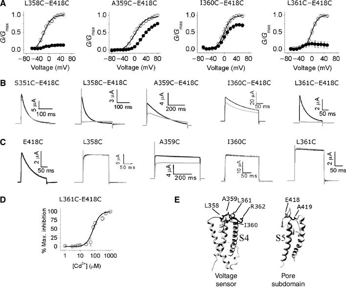
Effects of Cd2+ on K+ currents through single and double cysteine mutant channels. (A) Normalized G–V relationships calculated from peak currents recorded during depolarization to between −80 and 80 mV in 10 mV increments from a holding potential (h.p.) of −80 mV, before (○) and after (•) exposure to 100 μM Cd2+; interpulse interval was 20 s. The smooth curves correspond to data fitted to the Boltzmann function; n=4. (B, C) Channel activation. Representative current traces for the indicated double (B) and single (C) mutant channels, before (black) and after (grey) exposure to 100 μM Cd2+, recorded at a potential where the probability of channel opening is maximal, from an h.p. of −80 mV; interpulse interval was 20s; the insets show the time and current scale. (D) Dose–response curve for Cd2+-induced inhibition of the L361C–E418C mutant channel currents from which the EC50 value was calculated; n=4. (E) Structural models of the voltage sensor and the pore domain, based on KvAP and KcsA respectively; residues mutated are labelled.
Several S4 residues are close to the top of S5
Figure 1A and B shows that application of Cd2+ during depolarizing pulses inhibits K+ currents through the L358C–E418C, I360C–E418C and L361C–E418C double mutant channels; the effects seen with the A359C–E418C mutant channels were similar to those recorded from the A359C single S4 mutant channel. We suggest that the inhibition is caused by the ability of Cd2+ to form a metal bridge between cysteines at positions 358, 360 and 361 of S4 and the cysteine at 418 of the pore domain. Several control experiments support this conclusion: first, none of the corresponding single mutant channels (Figure 1C) or the wild-type channels (data not shown) were affected by Cd2+; this eliminates the possibility that the engineered single cysteines were able to form metal bridges with native residues. Second, when the 418C mutation was combined with a second cysteine at other nearby positions including 351 (present in S3–S4 loop; Figure 1B), or at a downstream S4 position (363–366), Cd2+ had no effect (data not shown), even though cysteines in these double mutants would be accessible to extracellularly applied Cd2+ during gating. These data suggest that positions 358, 360 and 361 of S4 can be spatially close to position 418 of the pore domain.
Further studies focused on L361C–E418C for the following reasons: first, this mutant showed a robust effect; second, position 361 is within the S4 helix and is known to move out of the membrane field during gating; finally, unlike the positions of the S3–S4 loop of the Shaker channel, the equivalent of position 361 in the KvAP crystal structure is clear. From the concentration dependence of the Cd2+ effect (Figure 1D), we have estimated an EC50 value of 54.4±4.4 μM for the L361C–E418C mutant channel. This value is higher than that reported for other pairs of cysteines in this region including S357C–E418C (Neale et al, 2003) and R362C–A419C (Laine et al, 2003). However, a number of factors could account for the relatively low affinity: first, the electrostatic potential around C361 would be considerably less favourable for Cd2+ binding due to the presence of a nearby positive charge at 362. Second, orientation of C361 relative to C418, and its pKa, may be different from that of other S4 cysteines. Finally, S4 is known to be extremely mobile, and this will reduce the duration of S4 contacts with S5.
State dependence of the proximity of S4 residues to the pore domain
We next investigated the state dependence of Cd2+ binding to the L361C–E418C mutant channels. Figure 2A shows that the L361C–E418C mutant channels were not inhibited when Cd2+ was applied for 2 min to cells held at −80 mV, where channels would be in their closed state, but subsequent depolarizing pulses caused rapid inhibition (filled circles). Moreover, when Cd2+ was applied to cells held at −60 mV (open circles), where channels just begin to activate, for the same length of time, maximal inhibition of currents occurred. Under control conditions, that is, in the absence of Cd2+ application (Figure 2A, bottom panel), however, there was no measurable loss of current, indicating that any accumulation of C-type inactivation at this activation potential is likely to be small. Thus, binding of Cd2+ to the channel most probably occurs during activation. The mechanism of inhibition, however, is not clear, but most likely involves Cd2+ binding to a preopen state. We cannot rule out the contribution of slow accumulation of an inactivated state to the Cd2+-induced inhibition. The state dependence of Cd2+ binding to L361C–E418C, however, is contrary to that reported for S357C–E418C channel, which binds Cd2+ in its resting conformation (Neale et al, 2003). The differences in the state dependence data of these two double mutant channels, however, can be explained in terms of the conventional helical screw motion: thus, position 357 would be close to 418 in the resting state of the channel, but during depolarization, when S4 undergoes outward translation, position 361 could move into the close proximity of position 418. Such a motion would entail that position 357 moves away from position 418, whereby Cd2+ would lose its ability to inhibit S357C–E418C mutant channel at depolarizing potentials. This possibility, however, could not be tested because we were unable to find an activation potential where C-type inactivation would be negligible for this mutant channel.
Figure 2.
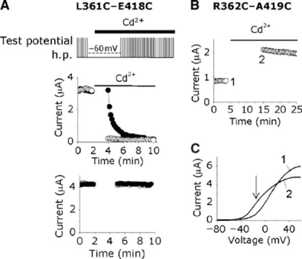
State dependence of the Cd2+ effect. (A) State dependence of the Cd2+ effect on the L361C–E418C double cysteine mutant channel. Perfusion protocol used is shown at the top. Peak currents were measured during depolarizing (+20 mV) test pulses (25 ms) from an h.p. of −80 mV, delivered at 10 s intervals. Solid bars indicate the period over which Cd2+ was applied. Data points represent experiments in which oocytes were held at the h.p. (•) or at −60 mV (○) during the gap in measurement. The bottom panel shows data from an identical experiment, without exposure to Cd2+. Representative data are presented from a single oocyte. (B) Cd2+ binds R362C–A419C double cysteine mutant channel in the closed state. Oocytes expressing this mutant channel was pretreated with 10 mM DTT for 1 h; currents were then measured during a voltage ramp (−120 to +60 mV), given at 30 s intervals from an h.p. of −100 mV; each data point in the top panel corresponds to current at −20 mV. Gap in the measurement indicates holding at −100 mV. (C) I–V relationships corresponding to data points labelled 1 and 2 (B); the arrow indicates the voltage point where currents were measured for (B).
We next examined the state-dependent binding of Cd2+ on the R362C–A419C double mutant channel, in the hope of finding further structural constraints for the resting and activated states of the channel. Previous studies have shown that Cd2+ has two effects on R362C–A419C: a leftward shift in the current (I)–voltage (V) relationship and a reduction in current amplitude at positive potentials (Laine et al, 2003). However, the state dependence of the Cd2+ effects was not clear. When we exposed this double mutant channel to Cd2+ at −100 mV (∼60 mV negative of activation threshold voltage), maximal leftward shift in I–V relationships (measured as an increase in current at −20 mV; Figure 2B) as well as a reduction of current at positive potentials (Figure 2C; compare trace 1 with trace 2) occurred. When rates of Cd2+ modification were examined using short (100 ms) and long (5 s) depolarizing pulse lengths, separated by 10 and 5 s intervals, respectively, no significant difference in the rates was observed (τ (min)=0.68±0.11 versus 0.69±0.06; P⩾0.05; n=3). These data indicate that the cysteine at position 362 can lie close to position C419 in both the resting and activated states of the channel. This finding was rather unexpected and seems inconsistent with the current models of S4 motion: a 180° rotation of S4 (Cha et al, 1999; Glauner et al, 1999) would move C362 away from the vicinity of C419 to the opposite face of the helix, making it unavailable for Cd2+ metal bridge formation. Rotation accompanied by vertical translocation (Glauner et al, 1999) would make it even more difficult for Cd2+ to form a metal bridge. Since we now know for certain, from the crystal structures, that both of these residues are in α-helical structures, our findings seem inconsistent with the two conventional models of S4 motion.
The top of S4 lies close to the top of S5 of its adjacent subunit in the resting state, but moves close to the top of S5 of its own subunit during depolarization
How does Cd2+ form a metal bridge between C362 and C419 in both the resting and activated states of the channel? The finding, at first, seems to suggest that S4 does not move much, but this would be inconsistent with the idea that S4 has to move significantly in order to move its charges across the membrane field (Ahern and Horn, 2004b). Could the nature of S4 movement therefore be different from those proposed in the conventional models? One possibility is as follows: S4 lies close to the top of S5 of its adjacent subunit in the closed state of the channel, but moves towards S5 of its own subunit during depolarization. This would explain why metal bridge formation between C362 and C419 shows apparent state independence.
To test this possibility, we used the tandem dimer (TD) approach: we made a tandem dimer containing two cysteines, one at position 361 of the first protomer and the other at 418 of the second (L361C–E418C TD). We chose to use 361C and 418C combination, because the effects of Cd2+ on L361C–E418C were robust and less complex compared to R362C–E419C and, more importantly, show a distinct state dependence. Furthermore, in L361C–E418C, the positive charge is preserved at position 362. Tetramers formed from the expression of such a tandem dimer will have the engineered cysteines on adjacent subunits, but not within the same subunit (Figure 3B, left). As such, any inhibitory effect of Cd2+ will be a consequence of an intersubunit metal bridge. Figure 3C (left) shows that Cd2+ had no inhibitory effect on L361C–E418C TD; a small leftward shift in the voltage–conductance relationship was seen, but this was similar to the effect seen with the L361C single mutant channel (data not shown). Thus the strong inhibition of the double mutant L361C–E418C by Cd2+ (Figure 1A and B), but complete absence of such an effect on the tandem dimer, suggests that the metal bridge between C361 and C418 is more likely intrasubunit in nature.
Figure 3.

Position 361 lies close to position 418 of its neighbouring subunit at resting potentials, but close to position 418 of its own subunit at activating potentials. (A, C) G–V relationships (measured as in Figure 1) for the indicated tandem dimers before (○) and after (•) exposure to 100 μM Cd2+; the insets show current traces before (black) and after (grey) exposure to Cd2+. (B) Schematic of the expected tetrameric arrangement of the protomers in the two tandem dimers. (D) Effect of successive applications of Cu2+ (200 nM), Cu-Phe (50 μM) and DMPS (0.5 mM) on currents (measured during 100 ms pulses to 40 mV from an h.p. of −80 mV, delivered at 10 s intervals) through L361C–E418C TD (left) and L361C–E418C/WT TD (right); application of reagents is indicated by horizontal bars. (E) State dependence of disulphide bridge formation for L361C–E418C TD (left) and L361C–E418C/WT TD (right). Following control recordings, Cu-Phe was applied to channels held at −120 mV (•) and 0 mV (○) for 2 min (shown as horizontal bars). After washing while holding at −80 mV, current measurements were recommenced. (F) Effect of successive applications of Cu-Phe and DMPS on L361C-WT TD.
Could the lack of inhibitory effect be because the channels assembled from the tandem dimers do not behave in the same way as those from individual subunits? To test this, we examined the effect of Cd2+ on another tandem dimer, S357C–E418C TD. Previous studies using coexpression of S357C and E418C have shown intersubunit crosslinking between C357 and C418 (see also Supplementary Figure 1 for biochemical evidence). Figure 3A shows that Cd2+ inhibited S357C–E418C TD; the extent of inhibition of S357C–E418C TD, albeit less (∼20% reduction in maximal conductance), is significant (P<0.05). The smaller inhibition, compared to the corresponding double mutants (Neale et al, 2003), may be attributed to the fact that the tandem dimers contain two potential Cd2+ bridging sites as opposed to four in the double mutants. Thus the lack of effect of Cd2+ on L361C–E418C TD does not appear to be due to tandem linking of the subunits.
To confirm the intrasubunit metal bridge formation between C361 and C418, we have examined the effect of Cd2+ on another tandem dimer, in which we have introduced L361C and E418C mutations into the first protomer and joined it to the wild-type protomer. The resulting construct, L361C–E418C/WT TD, allows intra- but not intersubunit metal bridges (Figure 3B, right). Figure 3C (right) shows that Cd2+ causes significant (41.5±9.9%; P<0.05) inhibition of this tandem dimer, providing further support to the proposition that position 361 of S4 moves into the close proximity of position 418 of its own subunit.
Why does C361 not form a metal bridge with C418 in the resting state? One possibility is that C361 may lie beyond the Cd2+ coordinating distance (or geometry) of C418 of the adjacent subunit in the resting state. To address this, we have used Cu-Phe reagent, which can detect longer range interactions because of the reagent's ability to trap cysteines in a stable disulphide bridge, when they encounter each other during thermal motions in a protein (Careaga and Falke, 1992). Consistent with this idea, Cu-Phe inhibited the L361C–E418C TD (Figure 3D, left) indicating that C361 is close enough to C418 of its adjacent subunit to undergo oxidation to a disulphide bridge, but too far for Cd2+ to form a metal bridge. Likewise, L361C–E418C/WT TD was also inhibited by Cu-Phe (Figure 3D, right), which is consistent with the idea that C361 can be close to C418 of its own subunit. The inhibition was largely resistant to Ringer's wash, but could be reversed with 2,3-dimercapto-1-propane-sulphonic acid (DMPS), indicating that inhibition is due to disulphide bridge formation. This effect was not caused by any free Cu2+ present in the reagent since prior application of free Cu2+ to these tandem dimers, at a concentration (200 nM) 10-fold higher than that calculated in our Cu-Phe reagent, caused no current loss (Figure 3D). Previous reports have shown that during depolarization C361 forms an intersubunit disulphide crosslink with its counterpart in a neighbouring subunit (Aziz et al, 2002). However, it was not demonstrated whether the crosslinking was between adjacent or diagonally placed subunits. Although the latter seems unlikely, we have examined the effect of Cu-Phe on L361C-WT TD (Figure 3F) to eliminate the possibility that the inhibition seen with our tandem dimers (Figure 3D) was not caused by C361–C361 crosslinking across diagonally placed subunits. The lack of effect supports our conclusion that the inhibition was indeed caused by the crosslinking of C361 to C418.
Thus C361 in the S4 helix appears to be able to form an intersubunit disulphide with C418 of the adjacent subunit as well as an intrasubunit disulphide with C418 of its own subunit. If our prediction that S4 interacts with the top of S5 of the adjacent subunit in the resting state, but with the top of S5 of its own subunit in the activated state were correct, then one would predict the two tandem constructs to exhibit opposite state dependence for disulphide bridge formation. This was indeed the case (Figure 3E): the intrasubunit disulphide in L361C–E418C/WT TD occurred when the cells were held at an activating potential (0 mV), but not at a hyperpolarizing potential (−120 mV) (Figure 3E, right); the inhibition during the 2 min exposure to Cu-Phe was 34±7% at 0 mV, which was significantly (P<0.01; n=4) greater than the inhibition of 10±1% at −120 mV. By contrast, the intersubunit disulphide bonding in L361C–E418C TD occurred when cells were held at a hyperpolarizing potential, but not at a depolarizing potential (Figure 3E, left); the inhibition during the 2 min exposure to Cu-Phe was 42.9±4.2% at −120 mV, which was significantly (P<0.01; n=4) greater than the inhibition of 9.9±4.6% at 0 mV.
The N-terminal ends of the S4 segments of the adjacent subunits become close during depolarization
The above studies suggest that during channel activation, the extracellular end of S4 moves from the top of S5 of the adjacent subunit towards the top of its own S5. Previous studies suggested that during depolarization, S4 segments move independently (Ledwell and Aldrich, 1999; Mannuzzu and Isacoff, 2000); if this is the case, then the S4 that moves first would become close to the top of the resting S4 of the adjacent subunit, bringing several of the uppermost S4 residues from adjacent subunits into the close proximity of each other (Figure 5E). This explains our previous observation (Aziz et al, 2002) that cysteines introduced at position 361 of S4 can be crosslinked by an intersubunit disulphide bridge. Besides 361, modelling data (Figure 5E; see Discussion) suggest that several other residues, including R362 and R365, could also become closely proximal. To test this, we have examined the effect of Cu-Phe on R362C and R365C. Figure 4 shows that both these mutant channels are inhibited by Cu-Phe and that the inhibition is reversed by the disulphide reducing agent, dithiothreitol (DTT). This inhibition was not due to free Cu2+ in the reagent (data not shown). To confirm that disulphide bridge formation has occurred between the engineered S4 cysteines, but not between an S4 cysteine and a native cysteine, we have performed the experiments on S4 cysteine mutants in the cysteine-less background. Again, Cu-Phe inhibited channel currents through the R365C mutant channel; the effect could not be reversed with Ringer's wash, but tris(2-carboxyethyl)phosphine hydrochloride (TCEP), a highly specific disulphide reducing agent (Neale et al, 2003), has reversed the effect. This confirms intersubunit disulphide bridge formation between cysteines at position 365 from neighbouring subunits. R362C in the cysteine-less background did not form functional channels. These data not only indicate that positions 362 and 365 of the Shaker channel approach one another during activation, but provide further evidence that the top of an S4 moves between the tops of S5 of its own and the adjacent subunits during gating.
Figure 5.
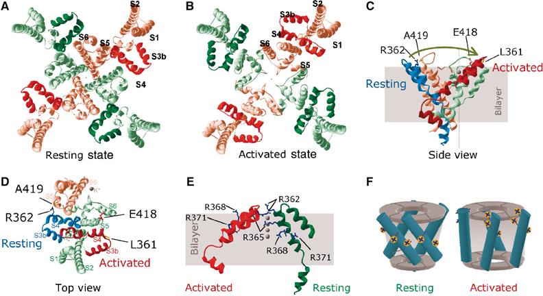
Proposed mechanism of voltage sensor paddle motion. (A, B) Structural models of resting (A) and activated (B) states of the Shaker potassium channel, reconstructed on the basis of elements derived from the crystal structures of KvAP, KcsA and MthK and the distance constraints obtained in this study (see Materials and methods and Discussion). Views are from the extracellular ends. Alternate subunits are shown in different colours, with the corresponding paddles in deeper colour; helices in one of the subunits are labelled. (C, D) Structural model depicting the possible movement of the voltage sensor paddle during activation. (C) Side view of a voltage sensor paddle with the attached S4–S5 linker in its resting state (blue) where the extracellular end of S4 is in close proximity of the top of S5 of the closed state pore subdomain (pink), belonging to the adjacent subunit. When activated, the paddle moves in the direction of the arrow towards S5 of its own pore subdomain, to attain an activated state (red), and to effect the pore subdomain to assume the open conformation (green); proximate residues are labelled. Other parts of the channel are omitted for clarity. K+ (grey spheres) are shown to indicate orientation. (D) Top view of the model in (C) with S1–S3a added to the green subdomain. (E) View of the relative positions of the voltage sensor paddle and the S4–S5 linker from adjacent subunits, one in the resting (green) and the other in the activated (red) state, highlighting reorientation of positive charges from an intracellular aspect to an extracellular one. All models were built using SWISS-MODEL (Schwede et al, 2003). (F) Schematic representation of changes in the position of S4 helices (cylinders) relative to the central pore domain and the orientation of positively charged groups during activation from the resting (left) to the activated (right) state.
Figure 4.
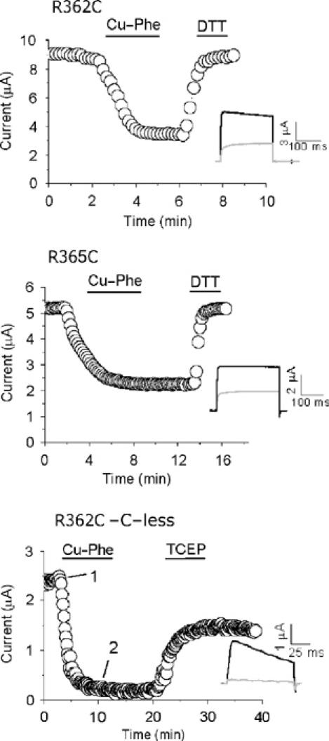
Intersubunit disulphide bond formation between S4 cysteines. Currents (at 40 mV; h.p. −80 mV; interpulse interval was 20 s) through R362C and R365C mutant channels in the wild-type background, and R365C in the cysteine-less Shaker background, were inhibited by Cu-Phe; the inhibition could be reversed with DTT or TCEP (solid bars indicate time periods during which reagents were applied). The insets show current traces before (black) and at the end of (grey) inhibition.
Discussion
In this study, we have exploited the ability of Cd2+ and Cu-Phe to induce metal and disulphide bridges, respectively, between spatially close, engineered cysteine sulphur atoms, to obtain distance constraints between several S4 positions and pore positions of the Shaker K channel. Cd2+ is able detect distances between cysteine β-carbons in the region of 4.2–6.5 Å, whereas Cu-Phe can identify cysteines located further apart (Careaga and Falke, 1992), including those that escape Cd2+ metal bridges. Our results show that activation of the channel is associated with marked changes in the intra- and intersubunit distance between the residues of the voltage sensor.
The extracellular end of S4 lies close to the top of S5 of the adjacent subunit in the closed state, but moves towards the top of S5 of its own subunit during activation
Our major findings are that residues at the extracellular end of S4 (positions 357, 361) lie in the close proximity of the top of S5 of the adjacent subunit in the resting state (Figures 1, 2 and 3 Neale et al, 2003), and that position 361 moves into the close proximity of position 418 of its own subunit during activation of the channel (Figure 3; Supplementary Figure 2). These data are inconsistent with the current models of S4 motion (Blaustein and Miller, 2004; Horn, 2004), but convey a new mechanism for S4 motion: the S4 helix lies in close proximity to the top of S5 of its adjacent subunit in the resting state, but moves into close proximity to the top of S5 of its own subunit during activation. We considered the distance constraints obtained in this study in the context of the crystal structures of KvAP (Jiang et al, 2003a), and other K channels (Doyle et al, 1998; Jiang et al, 2002), and made an attempt to develop models representing the resting and activated conformations of the Shaker channel.
Models of Shaker channels representing the resting and activated states
We first developed a homology model for the voltage sensor domain of the Shaker channel by taking elements from the two crystal structures, the isolated sensor domain and the full-length KvAP. For this, we have used the primary sequence from S1 to S4, with the S3–S4 loop reduced to three residues because in KvAP the corresponding region is three amino acids long. The truncation seems reasonable in as much as this does not appear to affect the function of the Shaker channel (Gonzalez et al, 2001), and in other Kv channels, such as Kv4.2, the linker is only three residues long (Li-Smerin et al, 2000b). We next replaced the S3b–S4 voltage sensor paddle and the S4–S5 linker (in the isolated structure) with the corresponding part from the full-length structure. The reason behind this is as follows: the structure of the paddle is identical between the isolated and full-length structures and the S4–S5 linker in the full-length structure is more likely to be in its natural conformation than in the isolated structure due to its physical connection to S5 (Jiang et al, 2003a).
The resultant chimeric S1–S4 voltage sensing domain was then used to position onto the structures of the pore domains representing the closed (KcsA-based; Doyle et al, 1998) and open (MthK-based; Jiang et al, 2002) conformational states. During docking, the S1–S4 domain was kept normal to the plane of the membrane, the S1–S2 and S3–S4 loops were always maintained in the extracellular phase (see Supplementary Figure 3 for evidence that the S3–S4 loop is extracellular in both the closed and open states) and the S4–S5 linker was kept as close to the bottom of S5 as possible. S4 was allowed to face the surface of the pore domain, with S1 and S2 near the periphery of the protein. Such a disposition is inconsistent with the full-length KvAP structure (which is acknowledged to be distorted), but is in complete agreement with crosslinking data from various laboratories (Broomand et al, 2003; Gandhi et al, 2003; Laine et al, 2003; Neale et al, 2003) as well as the recent electron microscopic data (Jiang et al, 2004). We then tilted the domain so that the top of S4 is close to the top of S5 of the adjacent subunit to simulate the resting conformation, and to the top of S5 of its own subunit to obtain the activated conformation of the channel. The state-determining distance constraints, derived from the metal and disulphide bridge data, were then applied to position individual residues.
The net outcome was that only the activated state structure could be modelled (Figure 5B). From this, the resting state model (Figure 5A) could be readily obtained by flipping the voltage sensor paddle (S3b–S4) and by simply bending the paddle at the natural bend points in the S3 loop (near the highly conserved proline 322) and the S2–S3a loop (near proline 302). The S4–S5 linker helix had to be repositioned to maintain physical proximity to the bottom of S5 by bending the flexible loop connecting S4 to the S4–S5 linker. It should be noted, however, that the positions of the S1 and S2 helices in the final model were dictated by the positioning of the voltage sensing paddle, maintaining their relative positions to the paddle as in the isolated voltage sensor structure. Due to the lack of supporting experimental evidence, no attempt was made to alter the position of the S1 and S2 helices.
In the recent publication of an electron microscope (EM) image of the KvAP channel protein in a suspected activated state (Jiang et al, 2004), the authors suggested two possible locations for the voltage sensing paddle. A comparison with our model for the activated state (Figure 5B) reveals that our position of the voltage sensor is in reasonable agreement with the position of the sensor in the EM image, depicted in Figure 3D of Jiang et al (2004). The location of the voltage sensing paddle next to the pore domain is also consistent with the tryptophan perturbation study (Li-Smerin et al, 2000a), which predicts direct interaction between the voltage sensor and the periphery of the pore domain.
S4 may move as an intact unit with S3b
Our resting and activated structural models (Figure 5A and B) suggest that during depolarization, the S3b–S4 paddle flips along the outer perimeter of the pore domain by ∼60° in a clockwise direction (viewed from the extracellular end; Figure 5C and D). We propose that S4 moves as an intact unit with S3b, because it is difficult to conceive that, with the connecting linker as short as three amino acids, as is found in some Kv channels (Li-Smerin et al, 2000b; Gonzalez et al, 2001), S4 can move by as much as ∼30 Å (intersubunit distance between the extracellular ends of S5) leaving S3b behind. Such a motion may explain why a helix breaking residue is always present in the middle of S3 of all voltage-gated ion channels; in potassium channels, it is a proline and in sodium and calcium channels it is either glycine or serine (Li-Smerin and Swartz, 2001). Unlike the model presented by Jiang et al (2003b), however, the paddle in our model moves along the periphery of the pore domain, between subunits. When the paddle begins to move, the space left behind may be filled with extracellular fluid. This may account for the malleable crevices and reshaping of the electric field surrounding S4 during channel activation (Larsson et al, 1996; Wang et al, 1999; Bell et al, 2004; Horn, 2004). Part of the paddle, however, is exposed to the lipid phase; this may allow changes in protein–lipid contact during the motion.
Independent movement of voltage sensors allows S4–S4 interaction
Since it is known that S4 segments move independently (Ledwell and Aldrich, 1999; Mannuzzu and Isacoff, 2000), such a motion could take the extracellular end of an activating S4 into close proximity of the extracellular end of the resting S4 of the adjacent subunit, as depicted in Figure 5E. This is supported by our previous experiments, as well as the data presented in Figure 4; cysteines at positions 361 (Aziz et al, 2002) and 362 and 365 (Figure 4) can be induced to form intersubunit disulphide bridges. These findings are inconsistent with the proposed helical screw mechanism (Glauner et al, 1999) as well as the tilt and twist motions (Cha et al, 1999), but can be readily accounted for by the current model and the paddle motion proposed by Jiang et al (2003b). In addition, the model suggests an explanation as to how S4 motion could be cooperative, that is, how the movement of one S4 could influence that of other subunits (Mannuzzu and Isacoff, 2000). When the top of S4 (activating) approaches the top of its adjacent S4 (resting), the charged residues (especially the top two) would exert an ever increasing repulsive force on the resting S4, prompting it to move towards its activated position. The process may repeat at the other resting S4 segments, thereby generating a cooperative motion of S4 segments—a property that is reflected in the cooperative nature of channel activation, seen with most voltage-gated channels (Ledwell and Aldrich, 1999; Mannuzzu and Isacoff, 2000).
Charge displacement during the flipping of the voltage sensor paddle
Any structural model for the voltage sensor motion must be able to explain charge movement across the membrane electric field. An inspection of the orientation of the side chains of the charged residues (Figure 5E and F) provides an insight into this: the charged head groups of the key arginines, R365, R368 and R371, face the inside of the cell in the resting state, but outside of the cell in the activated state. The measured distances between the guanidium groups in the resting and activated positions varied from 5 to 11 Å. These distances are estimates based on the conformation of the side chains as in the crystal structure of KvAP. The distances would be greater if the side chains are in an extended conformation (which is likely at the extremes of membrane potential). For example, reorientation of an arginine side chain attached to an α-helix, undergoing a flipping motion, can lead to its charge moving by as much as 19 Å. Since we do not know the exact boundaries of the membrane electric field, and since the morphology of the field is thought to change during activation (Horn, 2004), no attempt has been made to account for the known displacement of ∼3e per subunit in the Shaker channel (Schoppa et al, 1992; Aggarwal and MacKinnon, 1996; Seoh et al, 1996).
Relationship to previous work
Our model is also consistent with a number of published observations. It explains how depolarization could cause changes in the accessibility of cysteines to membrane-impermeable reagents (Yang and Horn, 1995; Larsson et al, 1996; Yusaf et al, 1996), transfer of protons by histidines substituted into S4 (Starace et al, 1997) and transfer of biotin groups tethered to substituted S4 cysteines (Jiang et al, 2003b). It explains well how channels containing histidine substitutions in S4 can function as H+ transporters and why the H+ transport activity shows a bell-shaped voltage dependence: at intermediate voltages, the rate of H+ transport is maximal because the frequency of alternate exposure of histidine residues to the intra- and the extracellular sides would be high, whereas at extreme voltages, they will be exposed either only to the inside (negative voltage) or to the outside (positive voltage). Our model explains why extreme truncation of the S3–S4 linker does not destroy the gating ability of the channel (Gonzalez et al, 2001). In addition, it could explain why the distance changes between S4 positions of the neighbouring subunits during channel activation, measured by LRET (Cha et al, 1999) and FRET (Glauner et al, 1999) experiments, are much smaller than expected, being on the order of ∼2 Å (Horn, 2000). The model is consistent with the distances between S4 and the pore measured using tetraethylammonium tethered to S4 residues (Blaustein et al, 2000). The model explains why the surface of the pore domain has gating-sensitive residues that form a broad stripe (Li-Smerin et al, 2000a); S3b–S4 may slide over this stripe during gating. The motion allows potential charge interactions between the positive charges of S4 and the negative charges of S2 (Tiwari-Woodruff et al, 1997; 2000). Finally, the unexpected state-independent effects of metal ions and disulphide-inducing agents observed for several S4 and pore domain double cysteine mutants, including 362C–419C (Laine et al, 2003), 353C–416C (Broomand et al, 2003), and 354C–416C, 355C–416C and 356C–416C (Gandhi et al, 2003), can be readily accounted for by the intra- and intersubunit interactions.
Conclusions
In conclusion, we have provided evidence that has led us to propose a new structural model for S4 motion in which the S3b–S4 paddle flips along the periphery of the central pore domain. This movement is accompanied by the reorientation of charged head groups associated with the S4 helix from the intracellular to the extracellular face, thereby explaining how the channel responds to changes in the membrane potential (accounting for charge motion). The question of how this electrically driven paddle motion triggers the mechanical opening of the channel's gates, however, remains to be addressed. However, based on our findings and the structural data (Jiang et al, 2003a), we propose a working model for electromechanical coupling of the voltage sensor to channel gates: during depolarization, when the paddle flips, the S4–S5 helix bends sharply at the hinge point (the flexible linker connecting S4 to S4–S5 helix) such that the S5 end of the S4–S5 linker is dragged away from the central pore axis. Such motion would pull the S5 helices outward causing the associated S6 helices to bend at their gating hinge points (Jiang et al, 2002), thereby leading to the opening of the activation gates and ion flow (see Supplementary movie).
Materials and methods
Mutagenesis and expression
Mutations were introduced by the QuikChange method (Stratagene) into the Shaker B cDNA clone (Shaker-IR), lacking the inactivation ball domain (residues 6–46) (Hoshi et al, 1990). Tandem dimers were constructed from protomers (kindly provided by Dr Yellen, Harvard Medical School, Boston) containing the desired mutations using the standard recombinant DNA methods. cRNA was prepared from Shaker-IR and its mutants and dimers using the T7 Megascript kit (Ambion) and injected into the stage V or VI oocytes isolated from Xenopus toads, killed by cervical dislocation after anaesthetization with 3-amino-benzoic acid ethyl ester (Yusaf et al, 1996). Oocytes were incubated in ND-96 solution supplemented with 100 μM DTT solution for 1–3 days at 18°C before recording currents.
Current recordings and chemical modification
Whole-cell currents were recorded from oocytes using two-electrode voltage clamp. Microelectrodes were filled with 3 M KCl and had resistances of 1–3 and 1–1.5 MΩ for the voltage and current electrodes, respectively. Currents were recorded at room temperature (20–23°C) in Ringer's solution (115 mM NaCl, 2.5 mM KCl, 1.8 mM CaCl2, 10 mM HEPES, pH 7.2). Details of protocols used for measurement of conductance–voltage (G–V) relationships, and the effects of modification reagents (Cd2+ and Cu-Phe) on current amplitudes and state-dependent effects are as described before (Neale et al, 2003); pulses were 25–500 ms long, delivered at intervals of 10–20 s (see figure legends). Concentration of free Cu2+ in the Cu-Phe reagent was calculated using REACT II software program (obtained from GL Smith, University of Glasgow, UK), in conjunction with standard dissociation constants (Martell and Smith, 1974). All data were generated from at least three oocytes, analysed using Origin 6.0 software and presented as representative recordings or mean±s.e.m.
Modelling
We have used amino-acid sequence alignment of KvAP with the Shaker channel as presented by Jiang et al (2003a) to build a three-dimensional homology model of the Shaker voltage sensing domain (residues 220–390). Residues 336–357 of the S3–S4 loop of the channel were omitted from this sequence, as the corresponding region was absent from KvAP. The resultant amino-acid sequence was submitted to SWISS-MODEL (Schwede et al, 2003) to obtain two models, one based on the isolated voltage sensor domain of KvAP (PDB accession code 1ORS) and the other on the basis of the full-length KvAP (PDB accession code 1ORQ). We then replaced the S3b–S4 plus the S4–S5 linker (residues 323–390) of the model derived from the isolated structure with the corresponding region from the model, based on the full-length KvAP. The resulting chimeric structure was used for positioning onto the closed and open state models of the Shaker pore domain (residues 391–480 for KcsA; 392–481 for MthK), which were built using the X-ray structures of KcsA (PDB accession code 1BL8) and MthK (PDB accession code 1LNQ), respectively.
Supplementary Material
Acknowledgments
We are grateful to Professor G Yellen for kindly providing the Shaker protomers, Professor MSP Sansom for helpful discussions and the Wellcome Trust for financial support.
References
- Aggarwal SK, MacKinnon R (1996) Contribution of the S4 segment to gating charge in the Shaker K+ channel. Neuron 16: 1169–1177 [DOI] [PubMed] [Google Scholar]
- Ahern CA, Horn R (2004a) Specificity of charge-carrying residues in the voltage sensor of potassium channels. J Gen Physiol 123: 205–216 [DOI] [PMC free article] [PubMed] [Google Scholar]
- Ahern CA, Horn R (2004b) Stirring up controversy with a voltage sensor paddle. Trends Neurosci 27: 303–307 [DOI] [PubMed] [Google Scholar]
- Aziz QH, Partridge CJ, Munsey TS, Sivaprasadarao A (2002) Depolarization induces intersubunit cross-linking in a S4 cysteine mutant of the Shaker potassium channel. J Biol Chem 277: 42719–42725 [DOI] [PubMed] [Google Scholar]
- Baker OS, Larsson HP, Mannuzzu LM, Isacoff EY (1998) Three transmembrane conformations and sequence-dependent displacement of the S4 domain in Shaker K+ channel gating. Neuron 20: 1283–1294 [DOI] [PubMed] [Google Scholar]
- Bell DC, Yao H, Saenger RC, Riley JH, Siegelbaum SA (2004) Changes in local S4 environment provide a voltage-sensing mechanism for mammalian hyperpolarization-activated HCN channels. J Gen Physiol 123: 5–19 [DOI] [PMC free article] [PubMed] [Google Scholar]
- Bezanilla F (2000) The voltage sensor in voltage-dependent ion channels. Physiol Rev 80: 555–592 [DOI] [PubMed] [Google Scholar]
- Blaustein RO, Cole PA, Williams C, Miller C (2000) Tethered blockers as molecular ‘tape measures' for a voltage-gated K+ channel. Nat Struct Biol 7: 309–311 [DOI] [PubMed] [Google Scholar]
- Blaustein RO, Miller C (2004) Ion channels: shake, rattle or roll? Nature 427: 499–500 [DOI] [PubMed] [Google Scholar]
- Broomand A, Mannikko R, Larsson HP, Elinder F (2003) Molecular movement of the voltage sensor in a K+ channel. J Gen Physiol 122: 741–748 [DOI] [PMC free article] [PubMed] [Google Scholar]
- Careaga CL, Falke JJ (1992) Structure and dynamics of Escherichia coli chemosensory receptors. Engineered sulfhydryl studies. Biophys J 62: 209–216 [DOI] [PMC free article] [PubMed] [Google Scholar]
- Cha A, Snyder GE, Selvin PR, Bezanilla F (1999) Atomic scale movement of the voltage-sensing region in a potassium channel measured via spectroscopy. Nature 402: 809–813 [DOI] [PubMed] [Google Scholar]
- Cohen BE, Grabe M, Jan LY (2003) Answers and questions from the KvAP structures. Neuron 39: 395–400 [DOI] [PubMed] [Google Scholar]
- Doyle DA, Morais CJ, Pfuetzner RA, Kuo A, Gulbis JM, Cohen SL, Chait BT, MacKinnon R (1998) The structure of the potassium channel: molecular basis of K+ conduction and selectivity. Science 280: 69–77 [DOI] [PubMed] [Google Scholar]
- Durell SR, Hao Y, Guy HR (1998) Structural models of the transmembrane region of voltage-gated and other K+ channels in open, closed, and inactivated conformations. J Struct Biol 121: 263–284 [DOI] [PubMed] [Google Scholar]
- Gandhi CS, Clark E, Loots E, Pralle A, Isacoff EY (2003) The orientation and molecular movement of a K+ channel voltage sensing domain. Neuron 40: 515–525 [DOI] [PubMed] [Google Scholar]
- Glauner KS, Mannuzzu LM, Gandhi CS, Isacoff EY (1999) Spectroscopic mapping of voltage sensor movement in the Shaker potassium channel. Nature 402: 813–817 [DOI] [PubMed] [Google Scholar]
- Gonzalez C, Rosenman E, Bezanilla F, Alvarez O, Latorre R (2001) Periodic perturbations in Shaker K+ channel gating kinetics by deletions in the S3–S4 linker. Proc Natl Acad Sci USA 98: 9617–9623 [DOI] [PMC free article] [PubMed] [Google Scholar]
- Hille B (2001) Ion Channels of Excitable Membranes. Sunderland, MA: Sinauer Associates Inc. [Google Scholar]
- Horn R (2000) A new twist in the saga of charge movement in voltage-dependent ion channels. Neuron 25: 511–514 [DOI] [PubMed] [Google Scholar]
- Horn R (2004) How S4 segments move charge. Let me count the ways. J Gen Physiol 123: 1–4 [DOI] [PMC free article] [PubMed] [Google Scholar]
- Hoshi T, Zagotta WN, Aldrich RW (1990) Biophysical and molecular mechanisms of Shaker potassium channel inactivation. Science 250: 533–538 [DOI] [PubMed] [Google Scholar]
- Jiang QX, Wang DN, MacKinnon R (2004) Electron microscopic analysis of KvAP voltage-dependent K+ channels in an open conformation. Nature 430: 806–810 [DOI] [PubMed] [Google Scholar]
- Jiang Y, Lee A, Chen J, Cadene M, Chait BT, MacKinnon R (2002) The open pore conformation of potassium channels. Nature 417: 523–526 [DOI] [PubMed] [Google Scholar]
- Jiang Y, Lee A, Chen J, Ruta V, Cadene M, Chait BT, MacKinnon R (2003a) X-ray structure of a voltage-dependent K+ channel. Nature 423: 33–41 [DOI] [PubMed] [Google Scholar]
- Jiang Y, Ruta V, Chen J, Lee A, MacKinnon R (2003b) The principle of gating charge movement in a voltage-dependent K+ channel. Nature 423: 42–48 [DOI] [PubMed] [Google Scholar]
- Laine M, Lin MC, Bannister JP, Silverman WR, Mock AF, Roux B, Papazian DM (2003) Atomic proximity between S4 segment and pore domain in Shaker potassium channels. Neuron 39: 467–481 [DOI] [PubMed] [Google Scholar]
- Larsson HP, Baker OS, Dhillon DS, Isacoff EY (1996) Transmembrane movement of the Shaker K+ channel S4. Neuron 16: 387–397 [DOI] [PubMed] [Google Scholar]
- Ledwell JL, Aldrich RW (1999) Mutations in the S4 region isolate the final voltage-dependent cooperative step in potassium channel activation. J Gen Physiol 113: 389–414 [DOI] [PMC free article] [PubMed] [Google Scholar]
- Li-Smerin Y, Hackos DH, Swartz KJ (2000a) A localized interaction surface for voltage-sensing domains on the pore domain of a K+ channel. Neuron 25: 411–423 [DOI] [PubMed] [Google Scholar]
- Li-Smerin Y, Hackos DH, Swartz KJ (2000b) α-helical structural elements within the voltage sensing domains of a K+ channel. J Gen Physiol 115: 33–49 [DOI] [PMC free article] [PubMed] [Google Scholar]
- Li-Smerin Y, Swartz KJ (2001) Helical structure of the COOH terminus of S3 and its contribution to the gating modifier toxin receptor in voltage-gated ion channels. J Gen Physiol 117: 205–218 [DOI] [PMC free article] [PubMed] [Google Scholar]
- Liu Y, Jurman ME, Yellen G (1996) Dynamic rearrangement of the outer mouth of a K+ channel during gating. Neuron 16: 859–867 [DOI] [PubMed] [Google Scholar]
- Mannuzzu LM, Isacoff EY (2000) Independence and cooperativity in rearrangements of a potassium channel voltage sensor revealed by single subunit fluorescence. J Gen Physiol 115: 257–268 [DOI] [PMC free article] [PubMed] [Google Scholar]
- Martell AE, Smith RE (1974) Critical Stability Constants. New York: Plenum Press [Google Scholar]
- Neale EJ, Elliott DJ, Hunter M, Sivaprasadarao A (2003) Evidence for intersubunit interactions between S4 and S5 transmembrane segments of the Shaker potassium channel. J Biol Chem 278: 29079–29085 [DOI] [PubMed] [Google Scholar]
- Schoppa NE, McCormack K, Tanouye MA, Sigworth FJ (1992) The size of gating charge in wild-type and mutant Shaker potassium channels. Science 255: 1712–1715 [DOI] [PubMed] [Google Scholar]
- Schwede T, Kopp J, Guex N, Peitsch MC (2003) SWISS-MODEL: an automated protein homology-modeling server. Nucleic Acids Res 31: 3381–3385 [DOI] [PMC free article] [PubMed] [Google Scholar]
- Seoh SA, Sigg D, Papazian DM, Bezanilla F (1996) Voltage-sensing residues in the S2 and S4 segments of the Shaker K+ channel. Neuron 16: 1159–1167 [DOI] [PubMed] [Google Scholar]
- Sigworth FJ (1994) Voltage gating of ion channels. Q Rev Biophys 27: 1–40 [DOI] [PubMed] [Google Scholar]
- Starace DM, Bezanilla F (2004) A proton pore in a potassium channel voltage sensor reveals a focused electric field. Nature 427: 548–553 [DOI] [PubMed] [Google Scholar]
- Starace DM, Stefani E, Bezanilla F (1997) Voltage-dependent proton transport by the voltage sensor of the Shaker K+ channel. Neuron 19: 1319–1327 [DOI] [PubMed] [Google Scholar]
- Tiwari-Woodruff SK, Lin MA, Schulteis CT, Papazian DM (2000) Voltage-dependent structural interactions in the Shaker K+ channel. J Gen Physiol 115: 123–138 [DOI] [PMC free article] [PubMed] [Google Scholar]
- Tiwari-Woodruff SK, Schulteis CT, Mock AF, Papazian DM (1997) Electrostatic interactions between transmembrane segments mediate folding of Shaker K+ channel subunits. Biophys J 72: 1489–1500 [DOI] [PMC free article] [PubMed] [Google Scholar]
- Wang MH, Yusaf SP, Elliott DJ, Wray D, Sivaprasadarao A (1999) Effect of cysteine substitutions on the topology of the S4 segment of the Shaker potassium channel: implications for molecular models of gating. J Physiol (Lond) 521: 315–326 [DOI] [PMC free article] [PubMed] [Google Scholar]
- Yang N, Horn R (1995) Evidence for voltage-dependent S4 movement in sodium channels. Neuron 15: 213–218 [DOI] [PubMed] [Google Scholar]
- Yellen G (2002) The voltage-gated potassium channels and their relatives. Nature 419: 35–42 [DOI] [PubMed] [Google Scholar]
- Yusaf SP, Wray D, Sivaprasadarao A (1996) Measurement of the movement of the S4 segment during the activation of a voltage-gated potassium channel. Pflugers Arch 433: 91–97 [DOI] [PubMed] [Google Scholar]
Associated Data
This section collects any data citations, data availability statements, or supplementary materials included in this article.