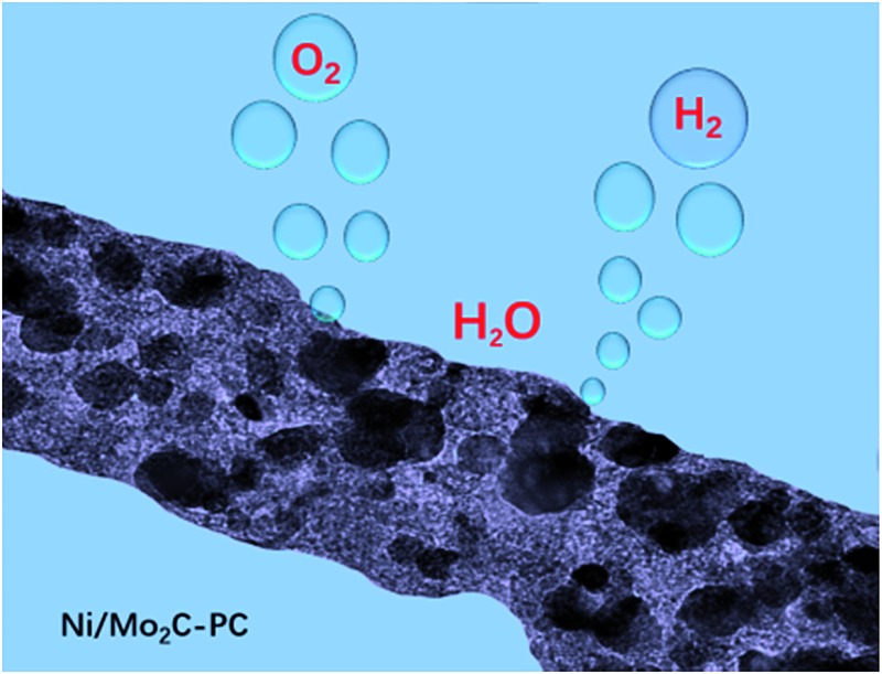
 A new porous carbon-supported Ni/Mo2C composite exhibits high activity towards both the hydrogen evolution reaction and oxygen evolution reaction for overall water splitting.
Abstract
The development of active, stable and low-cost electrocatalysts towards both the hydrogen evolution reaction (HER) and oxygen evolution reaction (OER) for overall water splitting remains a big challenge. Herein, we report a new porous carbon-supported Ni/Mo2C (Ni/Mo2C-PC) composite catalyst derived by thermal treatment of nickel molybdate nanorods coated with polydopamine, which efficiently and robustly catalyses the HER and OER with striking kinetic metrics in alkaline electrolyte. The catalyst affords low onset potentials of –60 mV for the HER and 270 mV for the OER, as well as small overpotentials of 179 mV for the HER and 368 mV for the OER at a current density of 10 mA cm–2. These results compare favorably to Mo2C-PC, Ni-PC, and most other documented Ni- and Mo-based catalysts. The high activity of Ni/Mo2C-PC is likely due to electron transfer from Ni to Mo2C, leading to a higher Ni valence and a lower Mo valence in the Ni/Mo2C-PC catalyst, as these are HER and OER active species and thus account for the enhanced activity. Remarkably, our home-made alkaline electrolyser, assembled with Ni/Mo2C-PC as a bifunctional catalyst, can enable a water-splitting current density of 10 mA cm–2 to be achieved at a low cell voltage of 1.66 V.
Introduction
With the rapid depletion of fossil fuels, the production of clean hydrogen fuels from water via electro/photochemical water splitting has become a very promising approach.1–8 The electrochemical water-splitting reaction includes a cathodic hydrogen evolution reaction (HER) and an anodic oxygen evolution reaction (OER), both of which have substantial overpotential (η) requirements.3,5,9 Diverse catalysts have been designed and prepared to reduce the η value for more economical utilization of energy.3,5,10,11 Currently, Pt-based metals show the best activity for the HER, and Ru/Ir-based materials are the benchmark catalysts for the OER.12–16 However, the low earth abundance and high cost of these metals significantly limit their widespread use, and thus the development of cost-effective and efficient alternative catalytic materials is highly demanded.17
Recently, 3d metal-based materials (e.g., Ni, Co, Fe and Mn) have been intensively developed as HER catalysts, among which it was established that Ni-based catalysts exhibited optimum performance in alkaline electrolyte, owing to the optimum OH–Ni2+δ (0 ≤ δ ≤ 1.5) bond strength that allows favorable intermediate adsorption.5 Ni and its alloy composites have been applied as alkaline HER catalysts in the water-splitting industry for decades.18–20 However, the main drawback of this catalyst is that its activity is easily lost after long-term operation because of the agglomeration and dissolution of the catalyst components.21,22 Therefore, substantial improvements in activity and stability are greatly needed. Substantial studies have revealed that coupling different functional species together can lead to significant performance gain owing to synergistic effects, such as the synergism occurring in the CoSe2/Mn3O4 and CoSe2/MoS2 composite catalysts developed by our group.6,12 Very recently, molybdenum carbide (Mo2C) has attracted great attention as a HER catalyst, because of its good stability, high electrical conductivity, and its similar electronic structure to Pt-group metals.23–27 In view of the above considerations, chemically coupling Ni with Mo2C is supposed to result in an improved HER catalytic activity.28 Moreover, such combination is also likely to realize outstanding OER performance owing to the presence of OER-active Ni.29–32 This catalyst design eventually will lead to a new bifunctional catalyst for efficient overall water splitting application, which is highly desirable for electrolyser development.33
Herein, we report the synthesis of a new composite catalyst by embedding Mo2C and Ni nanoparticles into porous carbon nanorods (Ni/Mo2C-PC) through thermal treatment of nickel molybdate (NiMoO4) nanorods coated with polydopamine, which is cost-effective and delivers highly active and stable performance for the HER with a low onset potential of –60 mV and a high exchange current density of 0.20 mA cm–2. Meanwhile, Ni/Mo2C-PC was found to be active as an OER catalyst with an onset potential of 270 mV and it can offer a current density of 10 mA cm–2 at a small η value of 368 mV. Intriguingly, our home-made alkaline electrolyser using Ni/Mo2C-PC as both cathodic and anodic catalysts can operate at a current density of 10 mA cm–2 with a small cell voltage of merely 1.66 V, and performs robustly. Our results suggest methods of designing and synthesizing efficient bifunctional catalysts based on low-cost nickel and molybdenum carbide, which could open the way to economic electrolysers for large-scale production of H2 fuels.
Results and discussion
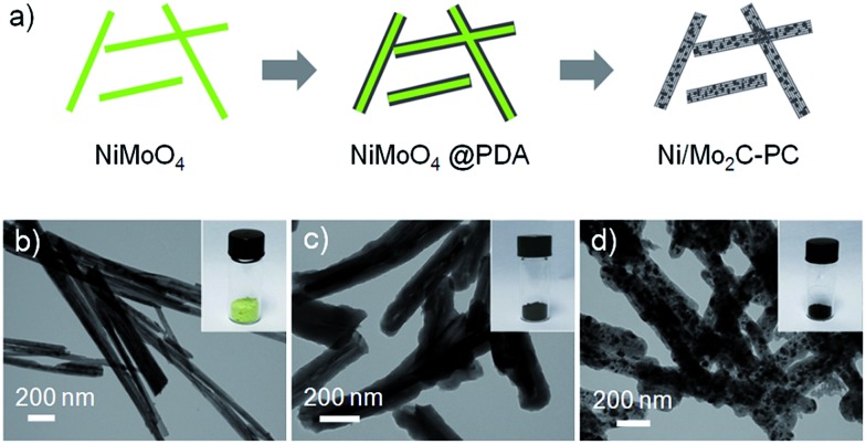
An illustration of the synthesis of the Ni/Mo2C-PC catalyst is shown in Fig. 1a (see the ESI for details†). We first prepared NiMoO4 nanorods with a diameter of 40–80 nm by a simple hydrothermal process as described in our previous work (Fig. 1b and S1, ESI†).34 Then a uniform polydopamine (PDA) shell was coated on the NiMoO4 nanorods in a Tris buffer solution (pH 8.5), and well-defined NiMoO4@PDA nanorods were obtained after polymerization for 24 h (Fig. 1c). Then the obtained dried powder was transferred into a tube furnace and annealed at 800 °C for 2 h under an Ar atmosphere, which eventually led to the generation of the black Ni/Mo2C-PC catalyst (Fig. 1d).
Fig. 1. (a) Illustration of the synthesis of Ni/Mo2C-PC from NiMoO4 nanorods. (b–d) TEM images of (b) NiMoO4, (c) NiMoO4@PDA, and (d) Ni/Mo2C-PC. Insets are the corresponding digital photographs.
In order to understand the phase transformation during the annealing process, powder X-ray diffraction (XRD) was performed for NiMoO4@PDA samples annealed at different temperatures ranging from 500 °C to 900 °C (Fig. S2a, ESI†). The XRD pattern at lower temperature was not recorded because of the very weak diffraction resulting from uncarbonized PDA. The strong metallic Ni phase (JCPDS no. 04-0850) and weak MoO2 phase (JCPDS no. 32-0671) can be detected for the sample annealed at 500 °C. Upon increasing the temperature to 600 °C, the diffraction peaks from MoO2 became obvious. This MoO2 phase, however, disappeared upon further increasing the temperature to 700 °C, while a new Mo2C phase (JCPDS no. 35-0787) appeared, which remained unchanged even when increasing temperatures to 800 °C and 900 °C. The metallic Ni phase existed in all samples from 500 °C to 900 °C. Based on these results, the formation of the Ni/Mo2C-PC composite with increased annealing temperature can be reasonably speculated to be the reaction described in eqn (1). Transmission electron microscope (TEM) images (Fig. S2b–e, ESI†) showed that the core of nanorods was maintained at 500 °C, and started to be destroyed from 600 °C. Along with the temperature increasing to 900 °C, these one-dimensional (1D) nanorods became porous and nanoparticles were formed and embedded in the carbon nanorods. Of note, the mass ratio of dopamine and NiMoO4 greatly affected the morphology and phase composition of the prepared samples (Fig. S3, ESI†). During the annealing process, the increasing carbon content will switch the reaction to eqn (2) for the formation of Ni/Mo2C-PC. The optimal mass ratio and temperature for achieving the Ni/Mo2C-PC composite were 1.5 and 800 °C, respectively. For comparison, Mo2C-PC, Ni-PC, and PC can be prepared using similar methods (Fig. S4 and S5, ESI†).
| NiMoO4 + C → Ni + MoO2 → Ni + Mo2C | 1 |
| NiMoO4 + C → Ni + MoO2 + MoNi → Ni + Mo2C + MoNi → Ni + Mo2C | 2 |
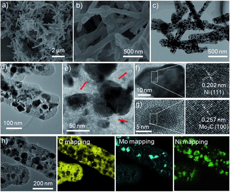
Scanning electron microscopy (SEM) and TEM images showed that the as-obtained 1D Ni/Mo2C-PC composite has a diameter of 150–200 nm and a length of up to 2–4 μm (Fig. 2a–c). The rod-like structure has a smooth surface with particulate Ni and Mo2C encapsulated within the carbon shells. Enlarged TEM images (Fig. 2d and e and S6a, ESI†) revealed the interesting porous structure of Ni/Mo2C-PC, which might benefit the access of electrolyte and reactants to active sites and thereby offer improved catalytic performance.35–37 N2 adsorption–desorption isotherms and pore size distribution curves showed that the mesoporous composite has a Brunauer–Emmett–Teller surface area of 89.5 m2 g–1 and a pore volume of 0.147 cm3 g–1 (Fig. S7a, ESI†).
Fig. 2. (a) Low and (b) high magnification SEM images of Ni/Mo2C-PC. (c) Low and (d and e) high magnification TEM images of Ni/Mo2C-PC; the arrows in (e) show the porosity. (f and g) HRTEM images of (f) Ni and (g) Mo2C. (h) EELS elemental mapping images of C, Mo, and Ni.
High-resolution TEM (HRTEM) images (Fig. 2f and g) showed that the spacings of 0.202 nm and 0.257 nm correspond to the (111) plane of Ni and the (100) plane of Mo2C, respectively. Fig. S6b (ESI†) uncovered the spacing of 0.345 nm, which corresponds to the (002) plane of graphite-like carbon layers. Elemental mapping revealed the uniform spatial distribution of Ni and Mo over the selected detection range of the Ni/Mo2C-PC composite (Fig. 2h and S6c, ESI†). It is noted that the size of Ni is larger than that of Mo2C, presumably due to the easier aggregation of Ni during the high-temperature treatment.20 Strikingly, most of the Ni nanoparticles were surrounded by Mo2C nanoparticles, suggesting possible electron transfer between them. The Raman spectrum showed that two distinct peaks were located at about 1350 and 1590 cm–1, which can be assigned to the D and G bands of carbon, respectively (Fig. S7b, ESI†). Moreover, the I D/I G value (intensity ratio of the D band to G band) is about 0.9, demonstrating the presence of significant structural defects within Ni/Mo2C-PC.38 Based on the inductively coupled plasma mass spectrometry result, the Ni and Mo2C contents in the Ni/Mo2C-PC composite were calculated as about 20.9 wt% and 29.7 wt%, respectively.
We then evaluated the HER performance of the Ni/Mo2C-PC composite using a typical three-electrode system in N2-saturated 1 M KOH electrolyte. The optimized mass loading of the Ni/Mo2C-PC catalyst on a glassy carbon electrode was determined to 0.50 mg cm–2 (Fig. S8, ESI†). The HER activities as a function of annealing temperature and mass ratio of precursor were also studied (Fig. S9, ESI†). The sample prepared at 500 °C was almost HER-inactive, and increasing the annealing temperature led to enhanced activity. The optimum HER activity was achieved for the sample prepared at 800 °C, which can probably be ascribed to the balance of electrical conductivity, active site and porosity.39,40 Furthermore, when keeping the annealing temperature at 800 °C, the mass ratio of dopamine and NiMoO4 was 1.5 for optimum HER activity.
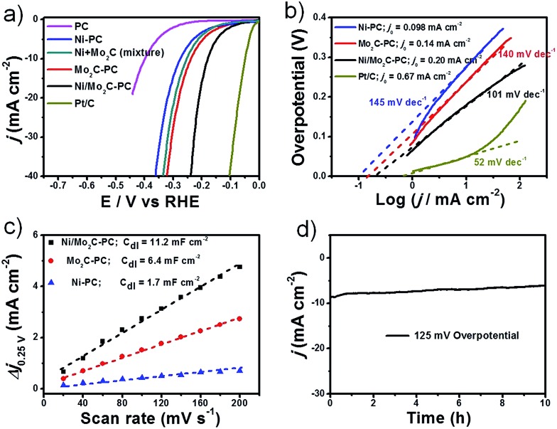
The HER polarization curves for Mo2C-PC along with Ni-PC, PC, the Ni/Mo2C physical mixture, and commercial Pt/C for comparison, are presented in Fig. 3a. The Mo2C-PC and Ni-PC samples showed a similar onset potential of about –90 mV. However, the Ni/Mo2C-PC composite showed a much lower onset potential of about –60 mV. Meanwhile, the η value required to reach a current density of 10 mA cm–2 (η 10) is 179 mV for Ni/Mo2C-PC, which is 59 and 96 mV smaller than that of Mo2C-PC and Ni-PC, respectively. Strikingly, the onset potential and η 10 mean that the Ni/Mo2C-PC catalyst also performs superiorly to most documented non-noble-metal catalysts in basic electrolytes, such as Co–P/Co–PO4,41 Co-NRCNTs,42 WN array,43 Mo2C,44 CoOx@CN,45 CoP array,46 NiFe LDH/Ni foam,33 and so on (Table S1, ESI†). For the physical mixture of Mo2C-PC and Ni-PC, its HER activity was located between those of its counterpart catalysts and was substantially inferior to that of the Ni/Mo2C-PC catalyst, suggesting that the strong chemical coupling effect works in the Ni/Mo2C-PC composite catalyst. The corresponding Tafel plots of the studied catalysts are presented in Fig. 3b. Although still larger than the Tafel slope of 52 mV dec–1 for the Pt/C catalyst, the Tafel slope of 101 mV dec–1 for Ni/Mo2C-PC is much smaller than that of Mo2C-PC (140 mV dec–1) and Ni-PC (145 mV dec–1), demonstrating faster HER kinetics. The Tafel slope of 101 mV dec–1 suggests that Volmer step-water dissociation (H2O + e– ↔ H + OH–) is the rate-determining step in alkaline media.1,5 The inherent HER activity of these catalysts was assessed by the exchange current density (j 0) based on the Tafel plots (Fig. 3b).4 Remarkably, Ni/Mo2C-PC exhibited a very high j 0 value of 0.20 mA cm–2, which stands at the same order of magnitude as that for the Pt/C catalyst (0.67 mA cm–2), and outperforms Mo2C-PC and Ni-PC catalysts, as well as most reported catalysts.23,24,47,48
Fig. 3. HER tests in 1 M KOH. (a) The HER polarization plots for different catalysts at a scan rate of 5 mV s–1. (b) Tafel plots and exchange currents for different catalysts. (c) The capacitive currents at different scan rates. The mass loading is 0.50 mg cm–2 supported on a glassy carbon (GC) electrode for the tests in (a–c). (d) The stability test for Ni/Mo2C-PC on Ni foam with a loading of 2 mg cm–2.
The double-layer capacitance (C dl), which was proportional to the electrochemically active surface area,47–49 was also measured to probe the advantages of the Ni/Mo2C-PC catalyst (Fig. 3c and S10a, ESI†). The C dl of 11.2 mF cm–2 for Ni/Mo2C-PC was 2–6 times larger than that of other studied catalysts, indicating that more active sites are available for the Ni/Mo2C-PC catalyst. Furthermore, electrochemical impedance spectroscopy (EIS) was used to study electrode kinetics during the HER process. The Nyquist plots indicated that the smallest charge transfer resistance (R ct) of 20 Ω was enabled on the Ni/Mo2C-PC catalyst, comparing favorably to 46 Ω and 69 Ω for Mo2C-PC and Ni-PC, respectively (Fig. S10b†). The smallest R ct of the Ni/Mo2C-PC catalyst can be attributed to its porous composite structure, which allows ultrafast faradaic processes and thus improves the HER kinetics. The long-term stability of Ni/Mo2C-PC was evaluated by loading a high catalyst amount of 2 mg cm–2 on Ni foam (Fig. 3d) and it showed good stability with only very little decay after a continuous 10 h test. We also evaluated the HER activity in acidic and neutral electrolytes with η 10 values of 210 mV and 250 mV, respectively (Fig. S11a, ESI†).
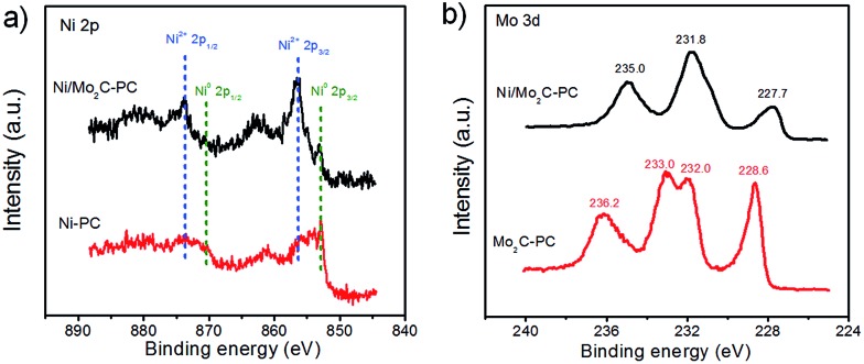
To understand the potential HER enhanced mechanism behind this new composite catalyst, we performed X-ray photoelectron spectroscopy (XPS) studies on the relevant catalysts (Fig. S12, ESI†). We found that our Ni/Mo2C-PC composite catalyst was doped with nitrogen, owing to the use of a nitrogen-containing precursor. However, our results showed that the nitrogen content in the studied catalysts had little effect on the HER activity, although the nitrogen content in nitrogen-doped carbon was described to be crucial to the HER activity.50,51 Therefore, we reasoned that the nitrogen dopant is not the main reason for the enhanced HER activity of Ni/Mo2C-PC (Fig. S12, ESI†). Due to the HER activity being sensitive to the valence states of metal element, we investigated the electronic structures of the Ni and Mo atoms with XPS.1,5 Ni 2p XPS spectra showed that the Ni-PC sample mainly contained metallic state Ni, whereas the majority of surface Ni in Ni/Mo2C-PC was oxidized with a +2 oxidation state (Fig. 4a).52,53 It is worth noting that Ni2+ species are believed to be effective active sites for water dissociation (the Volmer step), which is the critical HER step and consistent with the Tafel slope.1,5 Fig. 4b showed that the Mo 3d peaks in Ni/Mo2C-PC shifted to a lower binding energy as compared to Mo2C-PC, suggesting a lower Mo valence in the Ni/Mo2C-PC. Deconvolution of the Mo 3d XPS peaks (Fig. S12c, ESI†) provided detailed information on the Mo valence (0, +2, +3 and +4 for Ni/Mo2C-PC, and +2, +3, +4 and +6 for Mo2C-PC). Among these valence states of the Mo element, the Mo6+ species were documented to be inactive for the HER,25,26 suggesting that Ni/Mo2C-PC possibly has more HER active sites. According to these insights, we proposed that coupling Ni with Mo2C might enable electron transfer from Ni to Mo2C, leading to a higher Ni valence and lower Mo valence for the Ni/Mo2C-PC catalyst, as they were HER active and thus accounted for the enhanced HER activity.
Fig. 4. (a) High-resolution Ni 2p XPS spectra for Ni/Mo2C-PC and Ni-PC. (b) High-resolution Mo 3d XPS spectra for Ni/Mo2C-PC and Mo2C-PC.
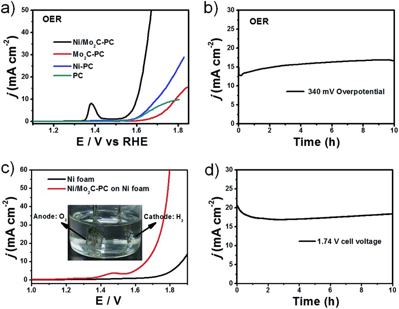
Furthermore, Ni/Mo2C-PC was also found to be active for the OER in alkaline electrolyte (Fig. 5a). This composite catalyst delivered an onset potential of 270 mV and η 10 of 368 mV, which are substantially superior to those of Ni-PC. Although the Ni content in Ni/Mo2C-PC (20.9 wt%) was lower than that in Ni-PC (47.6 wt%), Ni/Mo2C-PC had a higher content of Ni2+ species based on the XPS studies, which can act as OER active sites. This is consistent with the observed larger redox peak (Ni2+/Ni3+) during the OER operation (Fig. S13, ESI†).5,52 Therefore, the enhanced OER activity of Ni/Mo2C-PC can be ascribed to its higher Ni valence resulting from the strong electron transfer. We note that the OER activity of Ni/Mo2C-PC is remarkable, even if compared with documented Ni-based OER catalysts (Table S2, ESI†). Moreover, this composite catalyst is extremely stable. Long-term stability tests demonstrated that it can catalyze the OER without any current loss but a certain increase for 10 h under harsh OER running conditions (Fig. 5b).
Fig. 5. OER and water-splitting tests in 1 M KOH. (a) OER polarization plots with a loading of 0.50 mg cm–2 supported on a GC electrode. (b) The OER stability test for Ni/Mo2C-PC on Ni foam with a loading of 2 mg cm–2. (c) LSV curves of overall water splitting in a two-electrode configuration. The inset is the digital photo of H2 and O2 bubbles. (d) The stability of water splitting at an applied bias of 1.74 V for 10 h. The loadings of both cathode and anode for water splitting are 2 mg cm–2 supported on Ni foam.
Its excellent bifunctional catalytic properties inspired us to examine the possibility of using Ni/Mo2C-PC for practical water splitting. In commercial alkaline electrolysers, Ni foam was often used to support a catalyst, in view of its low cost, high conductivity and three-dimensional framework structure.33 We thus loaded the Ni/Mo2C-PC catalyst on Ni foam and used it as both the cathode and anode for a home-made electrolyser (Fig. 5c and S14, ESI†). Water-splitting current densities of 10 and 50 mA cm–2 can be achieved by applying cell voltages of 1.66 and 1.79 V, respectively, on the constructed device. The performance of Ni/Mo2C-PC as a dual catalyst for overall water splitting is excellent, performing better or comparably to other reported bifunctional water-splitting catalysts (Table S3, ESI†). Obvious H2 and O2 bubbles can be observed on the surface of both electrodes (inset in Fig. 5c). The long-term stability of the water-splitting reaction was evaluated by continuous operation at 1.74 V for 10 h (Fig. 5d). There was only a little degradation at the first hour, and after that the activity remained stable or even increased, demonstrating the excellent chemical stability and its great potential for real electrolyser systems. Lastly, we performed XRD and XPS measurements to analyze the variation of the Ni/Mo2C-PC catalyst after cyclic tests (Fig. S15, ESI†). Both the HER and OER cyclic tests didn't change the valence state of Ni, showing the high stability of Ni during the cyclic test. However, the Mo species wasn't very stable after long-term tests. It is still a big challenge to solve the problem of easy oxidation of Mo.23,54
Conclusions
In summary, we report a porous carbon-supported Ni/Mo2C catalyst prepared by thermal treatment of nickel molybdate nanorods coated with polydopamine. This low-cost composite catalyst can efficiently and robustly catalyse the HER and OER in alkaline solution with striking kinetic metrics, including low onset potentials of –60 mV for the HER and 270 mV for the OER, and a small η value of 179 mV for the HER and 368 mV for the OER to achieve a current density of 10 mA cm–2. The synergistic effect between Mo2C and Ni nanoparticles and their strong chemical coupling with highly conductive carbon are believed to account for the excellent catalytic activity. Our home-made alkaline electrolyser using Ni/Mo2C-PC as the bifunctional catalyst enables a current density of 10 mA cm–2 at a small cell voltage of merely 1.66 V, which also performs robustly. This work hints at the opportunity to couple cheap species for the creation of high-performance water-splitting catalytic materials, which is greatly needed for sustainable hydrogen economy.
Acknowledgments
We acknowledge funding support from the National Natural Science Foundation of China (Grant 21431006), the Foundation for Innovative Research Groups of the National Natural Science Foundation of China (Grant 21521001), the National Basic Research Program of China (Grants 2014CB931800, 2013CB931800), the Users with Excellence and Scientific Research Grant of Hefei Science Center of CAS (2015HSC-UE007, 2015SRG-HSC038), and Key Research Program of Frontier Sciences, the Chinese Academy of Sciences (Grant QYZDJ-SSW-SLH036).
Footnotes
References
- Subbaraman R., Tripkovic D., Strmcnik D., Chang K.-C., Uchimura M., Paulikas A. P., Stamenkovic V., Markovic N. M. Science. 2011;334:1256–1260. doi: 10.1126/science.1211934. [DOI] [PubMed] [Google Scholar]
- Wang H., Lee H.-W., Deng Y., Lu Z., Hsu P.-C., Liu Y., Lin D., Cui Y. Nat. Commun. 2015;6:7261. doi: 10.1038/ncomms8261. [DOI] [PMC free article] [PubMed] [Google Scholar]
- Jiao Y., Zheng Y., Jaroniec M., Qiao S. Z. Chem. Soc. Rev. 2015;44:2060–2086. doi: 10.1039/c4cs00470a. [DOI] [PubMed] [Google Scholar]
- Zheng Y., Jiao Y., Jaroniec M., Qiao S. Z. Angew. Chem., Int. Ed. 2015;54:52–65. doi: 10.1002/anie.201407031. [DOI] [PubMed] [Google Scholar]
- Subbaraman R., Tripkovic D., Chang K.-C., Strmcnik D., Paulikas A. P., Hirunsit P., Chan M., Greeley J., Stamenkovic V., Markovic N. M. Nat. Mater. 2012;11:550–557. doi: 10.1038/nmat3313. [DOI] [PubMed] [Google Scholar]
- Gao M.-R., Liang J.-X., Zheng Y.-R., Xu Y.-F., Jiang J., Gao Q., Li J., Yu S.-H. Nat. Commun. 2015;6:5982. doi: 10.1038/ncomms6982. [DOI] [PMC free article] [PubMed] [Google Scholar]
- Tang H., Hessel C. M., Wang J., Yang N., Yu R., Zhao H., Wang D. Chem. Soc. Rev. 2014;43:4281–4299. doi: 10.1039/c3cs60437c. [DOI] [PubMed] [Google Scholar]
- Lai X.-Y., Wang C.-R., Jin Q., Yu R.-B., Wang D. Sci. China Mater. 2015;58:192–197. [Google Scholar]
- Xu Y.-F., Gao M.-R., Zheng Y.-R., Jiang J., Yu S.-H. Angew. Chem., Int. Ed. 2013;52:8546–8550. doi: 10.1002/anie.201303495. [DOI] [PubMed] [Google Scholar]
- Feng L.-L., Yu G., Wu Y., Li G.-D., Li H., Sun Y., Asefa T., Chen W., Zou X. J. Am. Chem. Soc. 2015;137:14023–14026. doi: 10.1021/jacs.5b08186. [DOI] [PubMed] [Google Scholar]
- Morales-Guio C. G., Stern L.-A., Hu X. Chem. Soc. Rev. 2014;43:6555–6569. doi: 10.1039/c3cs60468c. [DOI] [PubMed] [Google Scholar]
- Gao M.-R., Xu Y.-F., Jiang J., Zheng Y.-R., Yu S.-H. J. Am. Chem. Soc. 2012;134:2930–2933. doi: 10.1021/ja211526y. [DOI] [PubMed] [Google Scholar]
- Zheng Y., Jiao Y., Zhu Y., Li L. H., Han Y., Chen Y., Du A., Jaroniec M., Qiao S. Z. Nat. Commun. 2014;5:3783. doi: 10.1038/ncomms4783. [DOI] [PubMed] [Google Scholar]
- Zheng Y.-R., Gao M.-R., Yu Z.-Y., Gao Q., Gao H.-L., Yu S.-H. Chem. Sci. 2015;6:4594–4598. doi: 10.1039/c5sc01335f. [DOI] [PMC free article] [PubMed] [Google Scholar]
- Zhang J., Qu L., Shi G., Liu J., Chen J., Dai L. Angew. Chem., Int. Ed. 2016;55:2230–2234. doi: 10.1002/anie.201510495. [DOI] [PubMed] [Google Scholar]
- Yin H., Zhao S., Zhao K., Muqsit A., Tang H., Chang L., Zhao H., Gao Y., Tang Z. Nat. Commun. 2015;6:6430. doi: 10.1038/ncomms7430. [DOI] [PubMed] [Google Scholar]
- Tang H., Yin H., Wang J., Yang N., Wang D., Tang Z. Angew. Chem., Int. Ed. 2013;52:5585–5589. doi: 10.1002/anie.201300711. [DOI] [PubMed] [Google Scholar]
- Zeng K., Zhang D. Prog. Energy Combust. Sci. 2010;36:307–326. [Google Scholar]
- Hall D. J. Electrochem. Soc. 1981;128:740–746. [Google Scholar]
- McKone J. R., Sadtler B. F., Werlang C. A., Lewis N. S., Gray H. B. ACS Catal. 2013;3:166–169. [Google Scholar]
- Hu W. Int. J. Hydrogen Energy. 2000;25:111–118. [Google Scholar]
- Wu L., He Y., Lei T., Nan B., Xu N., Zou J., Huang B., Liu C. T. Mater. Chem. Phys. 2013;141:553–561. [Google Scholar]
- Vrubel H., Hu X. Angew. Chem., Int. Ed. 2012;51:12703–12706. doi: 10.1002/anie.201207111. [DOI] [PubMed] [Google Scholar]
- Wu H. B., Xia B. Y., Yu L., Yu X.-Y., Lou X. W. Nat. Commun. 2015;6:6512. doi: 10.1038/ncomms7512. [DOI] [PMC free article] [PubMed] [Google Scholar]
- Zhao Y., Kamiya K., Hashimoto K., Nakanishi S. J. Am. Chem. Soc. 2015;137:110–113. doi: 10.1021/ja5114529. [DOI] [PubMed] [Google Scholar]
- Ma R., Zhou Y., Chen Y., Li P., Liu Q., Wang J. Angew. Chem., Int. Ed. 2015;54:14723–14727. doi: 10.1002/anie.201506727. [DOI] [PubMed] [Google Scholar]
- Lin H., Shi Z., He S., Yu X., Wang S., Gao Q., Tang Y. Chem. Sci. 2016;7:3399–3405. doi: 10.1039/c6sc00077k. [DOI] [PMC free article] [PubMed] [Google Scholar]
- Wang S., Wang J., Zhu M., Bao X., Xiao B., Su D., Li H., Wang Y. J. Am. Chem. Soc. 2015;137:15753–15759. doi: 10.1021/jacs.5b07924. [DOI] [PubMed] [Google Scholar]
- Chen S., Duan J., Ran R. J., Jaroniec M., Qiao S. Energy Environ. Sci. 2013;6:3693–3699. [Google Scholar]
- Sun T., Xu L., Yan Y., Zakhidov A. A., Baughman R. H., Chen J. ACS Catal. 2016;6:1446–1450. [Google Scholar]
- Diaz-Morales O., Ferrus-Suspedra D., Koper M. T. M. Chem. Sci. 2016;7:2639–2645. doi: 10.1039/c5sc04486c. [DOI] [PMC free article] [PubMed] [Google Scholar]
- Yin H., Tang Z. Chem. Soc. Rev. 2016;45:4873–4891. doi: 10.1039/c6cs00343e. [DOI] [PubMed] [Google Scholar]
- Luo J., Im J.-H., Mayer M. T., Schreier M., Nazeeruddin M. K., Park N.-G., Tilley S. D., Fan H. J., Grätzel M. Science. 2014;345:1593–1596. doi: 10.1126/science.1258307. [DOI] [PubMed] [Google Scholar]
- Ding Y., Wan Y., Min Y.-L., Zhang W., Yu S.-H. Inorg. Chem. 2008;47:7813–7823. doi: 10.1021/ic8007975. [DOI] [PubMed] [Google Scholar]
- Yin H., Tang H., Wang D., Gao Y., Tang Z. ACS Nano. 2012;6:8288–8297. doi: 10.1021/nn302984x. [DOI] [PubMed] [Google Scholar]
- Qi J., Lai X., Wang J., Tang H., Ren H., Yang Y., Jin Q., Zhang L., Yu R., Ma G., Su Z., Zhao H., Wang D. Chem. Soc. Rev. 2015;44:6749–6773. doi: 10.1039/c5cs00344j. [DOI] [PubMed] [Google Scholar]
- Lai X., Halpert J. E., Wang D. Energy Environ. Sci. 2012;5:5604–5618. [Google Scholar]
- Yu Z.-Y., Chen L.-F., Song L.-T., Zhu Y.-W., Ji H.-X., Yu S.-H. Nano Energy. 2015;15:235–243. [Google Scholar]
- Liang H.-W., Wei W., Wu Z.-S., Feng X., Müllen K. J. Am. Chem. Soc. 2013;135:16002–16005. doi: 10.1021/ja407552k. [DOI] [PubMed] [Google Scholar]
- Zhao S., Yin H., Du L., He L., Zhao K., Chang L., Yin G., Zhao H., Liu S., Tang Z. ACS Nano. 2014;8:12660–12668. doi: 10.1021/nn505582e. [DOI] [PubMed] [Google Scholar]
- Yang Y., Fei H., Ruan G., Tour J. M. Adv. Mater. 2015;27:3175–3180. doi: 10.1002/adma.201500894. [DOI] [PubMed] [Google Scholar]
- Zou X., Huang X., Goswami A., Silva R., Sathe B. R., Mikmeková E., Asefa T. Angew. Chem., Int. Ed. 2014;53:4372–4376. doi: 10.1002/anie.201311111. [DOI] [PubMed] [Google Scholar]
- Shi J., Pu Z., Liu Q., Asiri A. M., Hu J., Sun X. Electrochim. Acta. 2015;154:345–351. [Google Scholar]
- Morales-Guio C. G., Thorwarth K., Niesen B., Liardet L., Patscheider J., Ballif C., Hu X. J. Am. Chem. Soc. 2015;137:7035–7038. doi: 10.1021/jacs.5b03417. [DOI] [PubMed] [Google Scholar]
- Jin H., Wang J., Su D., Wei Z., Pang Z., Wang Y. J. Am. Chem. Soc. 2015;137:2688–2694. doi: 10.1021/ja5127165. [DOI] [PubMed] [Google Scholar]
- Tian J., Liu Q., Asiri A. M., Sun X. J. Am. Chem. Soc. 2014;136:7587–7590. doi: 10.1021/ja503372r. [DOI] [PubMed] [Google Scholar]
- Gao M.-R., Chan M. K. Y., Sun Y. Nat. Commun. 2015;6:7493. doi: 10.1038/ncomms8493. [DOI] [PMC free article] [PubMed] [Google Scholar]
- Kong D., Wang H., Lu Z., Cui Y. J. Am. Chem. Soc. 2014;136:4897–4900. doi: 10.1021/ja501497n. [DOI] [PubMed] [Google Scholar]
- Yan H., Tian C., Wang L., Wu A., Meng M., Zhao L., Fu H. Angew. Chem., Int. Ed. 2015;54:6325–6329. doi: 10.1002/anie.201501419. [DOI] [PubMed] [Google Scholar]
- Liu Y., Yu G., Li G.-D., Sun Y., Asefa T., Chen W., Zou X. Angew. Chem., Int. Ed. 2015;54:10752–10757. doi: 10.1002/anie.201504376. [DOI] [PubMed] [Google Scholar]
- Wang S., Wang J., Zhu M., Bao X., Xiao B., Su D., Li H., Wang Y. J. Am. Chem. Soc. 2015;137:15753–15759. doi: 10.1021/jacs.5b07924. [DOI] [PubMed] [Google Scholar]
- Gong M., Zhou W., Kenney M. J., Kapusta R., Cowley S., Wu Y., Lu B., Lin M.-C., Wang D.-Y., Yang J., Hwang B.-J., Dai H. Angew. Chem., Int. Ed. 2015;54:11989–11993. doi: 10.1002/anie.201504815. [DOI] [PubMed] [Google Scholar]
- Chen C., Kang Y. J., Huo Z. Y., Zhu Z. W., Huang W. Y., Xin H. L. L., Snyder J. D., Li D. G., Herron J. A., Mavrikakis M., Chi M. F., More K. L., Li Y. D., Markovic N. M., Somorjai G. A., Yang P. D., Stamenkovic V. R. Science. 2014;343:1339–1343. doi: 10.1126/science.1249061. [DOI] [PubMed] [Google Scholar]
- Wan C., Regmi Y. N., Leonard B. M. Angew. Chem., Int. Ed. 2014;53:6407–6410. doi: 10.1002/anie.201402998. [DOI] [PubMed] [Google Scholar]
Associated Data
This section collects any data citations, data availability statements, or supplementary materials included in this article.


