Abstract
Purpose
To introduce a simple analytical formula for estimating T2 from a single Double-Echo in Steady-State (DESS) scan.
Methods
Extended Phase Graph (EPG) modeling was used to develop a straightforward linear approximation of the relationship between the two DESS signals, enabling accurate T2 estimation from one DESS scan. Simulations were performed to demonstrate cancellation of different echo pathways to validate this simple model. The resulting analytic formula was compared to previous methods for T2 estimation using DESS and fast spin-echo scans in agar phantoms and knee cartilage in three volunteers and three patients. The DESS approach allows 3D (256×256×44) T2-mapping with fat suppression in scan times of 3–4 minutes.
Results
The simulations demonstrated that the model approximates the true signal very well. If the T1 is within 20% of the assumed T1, the T2 estimation error was shown to be less than 5% for typical scans. The inherent residual error in the model was demonstrated to be small both due to signal decay and opposing signal contributions. The estimated T2 from the linear relationship agrees well with reference scans, both for the phantoms and in vivo. The method resulted in less underestimation of T2 than previous single-scan approaches, with processing times 60 times faster than using a numerical fit.
Conclusion
A simplified relationship between the two DESS signals allows for rapid 3D T2 quantification with DESS that is accurate, yet also simple. The simplicity of the method allows for immediate T2 estimation in cartilage during the MRI examination.
Keywords: DESS, T2, Cartilage, Osteoarthritis
1. Introduction
The Double-Echo Steady-State (DESS) sequence offers distortion-free, SNR-efficient 3D-imaging with good contrast flexibility [1–3]. DESS is a gradient-spoiled steady-state sequence, collecting two echoes per repetition (TR), with the spoiler gradient separating the two echoes. The two signals, often labeled S1 (before the spoiler) and S2 (after the spoiler), have different contrast. The S1 signal is often said to have T1/T2 weighting and S2 to have a mixture of T2 and diffusion weighting, but in reality both the contrasts are quite complicated functions of the extrinsic scan parameters (TR, TE, flip angle α, gradient amplitude G and gradient duration τ) as well as the intrinsic tissue parameters (T1, T2, and diffusivity). While DESS has been used for various anatomies such as the breast [4,5] and the prostate [6,7], it has found particularly widespread use for musculoskeletal imaging, where for example it has been used in the Osteoarthritis Initiative (OAI) to determine Osteoarthritis (OA) progression [8].
To improve OA detection, DESS has been used for quantitative imaging of T2 and apparent diffusion coefficient (ADC) [9–12]. These have been found to correlate with collagen network organization and proteoglycan concentration, respectively [13,14]. A number of signal models have been developed to quantitatively describe both of the DESS signals and their dependency on tissue parameters. These include both closed-form and non-closed-form analytical methods as well as numerical methods [15–20].
Some methods model the DESS signals completely and can be considered fully accurate for a single T1, T2, and diffusivity in a voxel [16,17]. However, owing to their complexity, using these models for parameter estimation typically requires solving them with a numerical search over a predetermined solution set. This inhibits immediate, automatic creation of parameter maps right at the scanner, which would be of great value for clinical scans. Furthermore, the method in ref. [16], which describes the magnetization with a continued fraction, does not allow for pulsed gradients. For these reasons, approximate models are often used to estimate the desired parameter in spite of known errors. For example, in ref. [9], the following model, originally suggested in ref. [1], was used to estimate T2 from a single DESS scan:
| (1) |
This relationship essentially describes a spin echo relationship between S2 and S1 in consecutive TRs. Although this approach may offer useful results in spite of errors in T2, practical T2 mapping would benefit from a comparably simple analytical formula that is even more accurate.
In this work, we introduce a new model that can be used for T2 estimation from a single DESS scan. Our analysis demonstrates that higher-order echo pathways can often be ignored, based on pathway cancellation effects and signal decay, leading to a simple and accurate linear relationship between the signals from two DESS echoes. We validate the overall approach using simulations, phantom scans and in vivo knee scans.
2. Theory
2.1 Derivation of Simplified Signal Ratio
A simple yet accurate linear approximation of the relationship between the two DESS echoes can be derived by tracing the components that contribute to the magnetization, starting at S2, until we arrive at S1. We use the Extended Phase Graph (EPG) formalism, which decomposes magnetization into a basis of positively and negatively dephased transverse states (coefficients F0, F1, F2, …) as well as sinusoidally varying longitudinal states (coefficients Z0, Z1, Z2, …) [20,21]. The procedure is explained graphically in Fig. 1a–c, using similar graphical structures as those introduced by Scheffler et al. [18]. As explained by Weigel et al. [17,21], in the EPG formalism, the magnetization can be represented by a matrix of coefficents (Fn and Zn) that multiply transverse states with n cycles of positive or negative dephasing, and longitudinal states with n cycles of sinusoidal variation:
| (2) |
where an asterisk (*) denotes a complex conjugate. The observable signal is the DC transverse term F0. Relaxation and diffusion over time are represented by scaling of the elements (T1 relaxation is represented by an additive factor to the DC longitudinal term, Z0) and the effect of a gradient is represented by shifting the transverse coefficients Fn.
Figure 1.
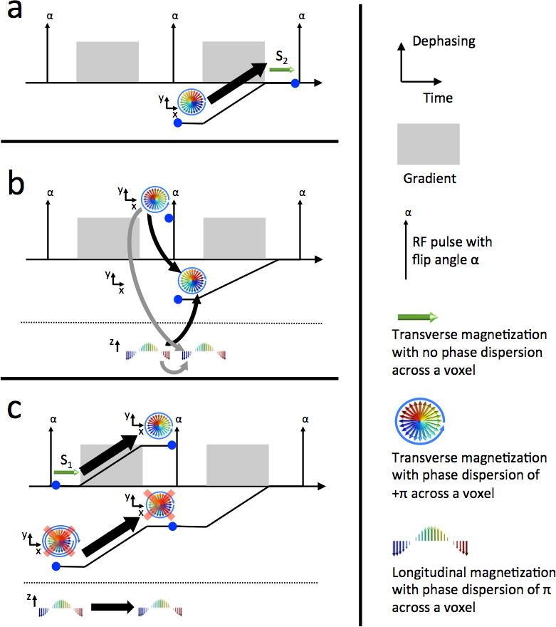
Diagrams showing dephasing across a voxel as a function of time using graphics similar to ref. [18]. In each panel, we consider the magnetization at the time of the right blue dot and examine the components from the time of the left blue dot that contributed to it. Graphical representations are shown of transverse and longitudinal states (above and below the dotted line, respectively). The accrued phase of the transverse magnetization is represented by the distance of the black line from the time axis. (a) The state that contributes to the measurable signal (S2) before the RF pulse is the “negatively dephased” signal following the previous RF pulse. (b) Two relevant paths before the RF pulse contribute to the state in panel a [21], shown with black arrows. These are transverse and longitudinal states that have a net dephasing from one gradient. They also contribute to the longitudinal state following the RF pulse (gray arrows). (c) The measurable signal following the previous RF pulse (S1), before dephasing by the gradient, contributes to the “positively dephased” transverse pathway from panel b. This is the desired endpoint so the pathway is not retraced further backward. The longitudinal pathway is not dephased by the gradient. The contribution of a third transverse pathway has been ignored since it comes from a doubly dephased signal, which can be neglected (shown with red x’s). This gives a recursive relationship between S1 and S2 that can be easily solved, resulting in Eq. (6).
The effects of T1/T2 decay, as well as diffusion, on state n, can be described by the scaling terms and (assuming the gradient in the center of the TR) [17]. The effect of an RF pulse with flip angle α and phase ϕ is represented by matrix multiplication with the matrix
| (3) |
Here, TR and TE represent the repetition and echo time, respectively, α is the flip angle, D is the diffusivity, and the dephasing per unit length induced by the unbalanced gradient is denoted by Δk =γGτ, where G and τ are the spoiler amplitude and duration, respectively, and γ is the gyromagnetic ratio. We label the states immediately before/after the RF pulse with −/+ superscripts, respectively. To determine a relationship between the two DESS signals, we look at the echo pathway of the observable signal immediately before the pulse, F0−, and write down the components that contributed to it. We repeat this until we reach the observable signal immediately after the pulse, F0+ (Fig. 1). As justified in Section 2.2, we will ignore signal contributions from states that have experienced two cycles of dephasing or more, as was done for the S2 signal in ref. [22]. We will assume ϕ=90°, resulting in real valued states, without loss of generality.
| (4a) |
| (4b) |
Combining Eqs. (4a–b) and using some algebra and trigonometric identities yields
| (5) |
Using the stated expressions for the decay factors as well as the fact that the observed signal magnitudes are and (where we have used that the two signals are out of phase and the second signal experiences T2′ rephasing), we arrive at the following expression:
| (6) |
This relationship, which assumes the echoes are acquired symmetrically during the TR (with the same duration from the RF pulse to S1 as from S2 to the subsequent RF pulse), provides a simple analytic estimate of T2 given an estimate of T1 and either minimal diffusion sensitivity or an estimate of diffusivity.
In the case of low spoiling (Δk ≈ 0), the model reduces to the following relationship:
| (7) |
For α = 90°, this further reduces to
| (8) |
In the case of very long T1 Eq. (7) becomes independent of flip angle and results in Eq. (1). This equation was presented by Bruder et al. and has been used by Welsch et al, for T2 estimation in cartilage [1,9]. However, this relationship results in errors unless the flip angle is close to 90° or TR/T1 is very small. The relationship also assumes weak spoiling so that diffusion effects may be ignored. Eq. (6) better approximates the signal over a large range of T1, flip angle α, and (zeroth) spoiler gradient moments. This is demonstrated in Fig. 2a, which shows the approximated signal from Eqs. (1) and (6), as well as highly accurate numerical computation of the signal using EPG matrices. The signal ratio is modeled with a typical T1 value of 1.2 s for cartilage [23], assuming both weak and strong spoiling (with spoiler moments of 0.001 and 156.6 mT/m•ms, respectively), as well as a long T1 value of 5 s for the weakly spoiled case, and a TR of 22.5 ms. Other parameters were TE = 6.5 ms, T2 = 40 ms, gradient duration τ = 3.4 ms, and ADC=1.6•10−3 mm/s. In order for Eq. (1) to be valid with smaller flip angles (about 20°–60°), T1 clearly needs to be much larger than TR.
Figure 2.
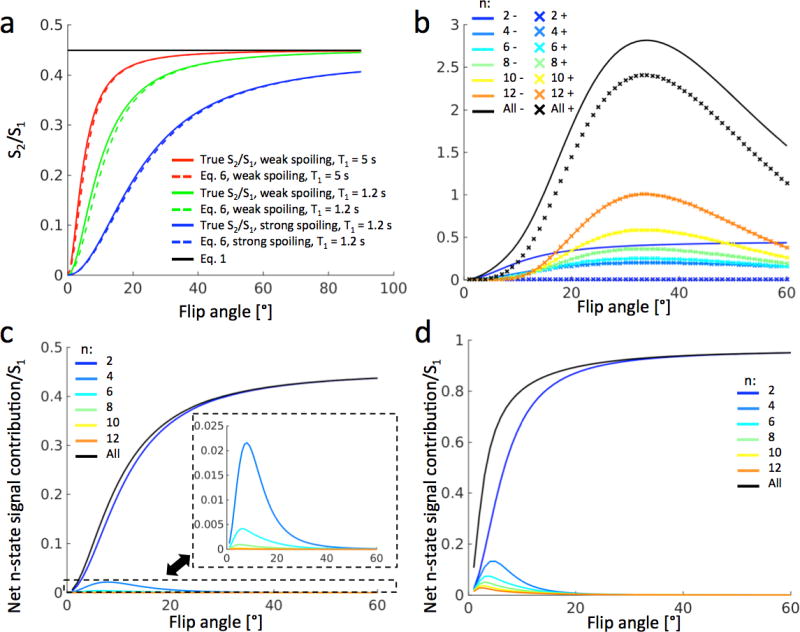
(a) Comparison of proposed model of Eq. (6) (dashed) with complete simulations (colored solids) and with the simple exponential model of Eq. (1) (black solid) in a tissue with T2 = 40 ms. The blue (bottom) curves correspond to strong spoiling (gradient moment 156.6 mT/m•ms) and the green (middle) curves to weak spoiling (gradient moment 0.001 mT/m•ms), both with T1 = 1.2 s. The red (top) curves correspond to weak spoiling and T1 = 5 s. The green curves represent DESS scans that can be used for T2 estimation in cartilage. (b) Positive (dashed) and negative (solid) contributions to S2/S1 from pathways spending 2–12 TRs in the transverse plane. The black curves represent the sum of the different pathways. For pathways of order 6 and above, the positive (×) curves overlap with the negative (solid) curves. (c) Net contributions from the pathways in panel b shows that pathways with more than 2 TRs in the transverse plane contribute minimally. (d) The same simulations as in panel c, performed for synovial fluid at 3T (T1 = 3.6 s, T2 = 0.77 s), showing that the proposed model (blue signal) approximates the true signal (black curve) well for flip angles above 20°, even for long T1 and T2.
2.2 Cancellation of higher-order echo pathways
The model in Eq. (6) performs well for two reasons. The equation neglects the contribution of echo pathways between S1 and S2 that have spent more than two TRs in the transverse plane. This is partly justified by simple signal decay – the more time that the magnetization spends in the transverse plane, the more it will be attenuated both by T2 relaxation and diffusion. However, a more important mechanism is the cancellation of echo pathways due to opposing phase, independent of relaxation. It is easy to show that all contributions to S2 that have experienced two transverse TRs will have negative phase relative to S1. However, this does not hold for higher order echo pathways. For example, if we denote TRs where the magnetization starts in the +/− nth transverse state or the nth longitudinal state by F+/−n and Zn, then the pathways F0F1F−2F−1 and F0Z1F1F−2F−1 will have opposite sign. By accumulating the contributions of all such pathways, the positive and negative contributions (relative to S1) of higher-order pathways can be modeled and compared. For example, by including pathways with two and four transverse TRs, Eq. (6) can be extended to
| (9) |
where B2− is the two-TR component given by Eq. (6), and B4+ and B4− are the four-TR components with the same and opposite phase to S1, respectively, given by
| (10) |
| (11) |
where
| (12) |
| (13) |
| (14) |
| (15) |
Fig. 2b displays the components Bn+ and Bn− for n = 2–12 over a range of flip angles with the same parameters as the green curve in Fig. 2a. The higher-order components with positive and negative phase have very similar magnitude. Therefore, they will have a negligible effect on the final answer, particularly for flip angles above 20° or short T2. This is demonstrated in Fig. 2c. This leads to Eq. (6) simulating the signal ratio S2/S1 very accurately, even in cases where there is very little T2 decay, such as in fluid. Fig. 2d shows the same simulation as Fig. 2c, but for synovial fluid at 3T, having T1 = 3.6 s and T2 = 0.77 s [23]. The higher-order pathways contribute more to the signal ratio in this case, especially for low flip angles, but Eq. (6) nonetheless approximates the true signal well for flip angles above 20°. The approximation of neglecting higher-order states was also used by Buxton [22]. In that work, only the S2 signal was modeled. If S1 in Eq. (6) is assumed to have no transverse pathway contributions, the two models agree, as further explained in the Discussion.
3. Methods
All scans were performed on a 3T 750 scanner (GE Healthcare, Waukesha, WI, USA). Informed consent was obtained from all subjects in accordance with the Institutional Review Board protocol at our institution. The volunteer scans used a 16-channel receive coil wrapped around the knee (GEM Flex by NeoCoil, Waukesha, WI, USA), the phantom scans used a single-channel transmit-receive wrist coil (GE BC-10 by Mayo Clinic, Rochester MN, USA), and the patient scans used an 8-channel transmit-receive knee coil (Knee Array Coil by Invivo, Gainesville, FL, USA).
3.1 Phantom scans
Three agar phantoms were scanned using DESS with scan parameters TR=13.4 ms, TE=3.9 ms, voxel size 0.47×0.47×3.0 mm3, spoiler moment 7.83 mT/m•ms and duration τ=3.4 ms, and flip angles α = 10°, 15°, 20°, 30°, 40°, and 50°. Fast spin-echo (FSE) scans with echo times TE = 17, 26, 34, 43, 51, 60, and 68 ms, TR = 1000 ms and voxel size 0.47×0.47×6.0 mm3 were performed and fitted to a monoexponential curve to obtain a reference T2. The T2 value was estimated from the DESS scans using Eqs. (1) and (7) and compared to the value resulting from the reference FSE scans. For Eq. (7), reference T1 values known to be T1-1 = 2000 ms, T1-2 = 1700 ms, and T1-3 = 1600 ms, measured with a 3TI MP-RAGE technique [24], and a flip angle measured with the Bloch-Siegert method [25], were used for processing each phantom.
3.2 Volunteer scans
To test Eq. (7) in vivo, a sagittal DESS scan was performed in the knee of three healthy volunteers. The scans used a spoiler with a moment of 15.66 mT/m•ms and duration 3.4 ms. Other parameters were α=25°, TR=22.5 ms, TE=6.5 ms, slice thickness 3.0 mm. A spectrally selective RF pulse was used. The T2 of the cartilage was again estimated using the linear approximations of Eqs. (1) and (7). Reference FSE scans were acquired with TE = 9, 18, 27, 36, 45, 54, 63, and 72 ms and TR = 1000 ms. Both scans were run with FOV = 13cm×13cm and acquisition matrix 384×384, which was automatically interpolated to 512×512 by the scanner. For T2 quantification using Eq. (7), T1=1.2 s, typical for cartilage at 3T [23], and the prescribed flip angle of α=25° were used. Eq. (7) has low sensitivity to T1, so small errors in the T1 assumption should not cause large errors in estimated T2. Furthermore, T1 in knee cartilage does not change much whereas T2 is sensitive to degeneration. For comparison, a T2 map using a full numerical fit was produced from the DESS scan as well. This involved computing a dictionary of signal ratios for T2 ranging between 10–100 ms (with a step size of 1 ms) using large EPG matrices (with 6 states) and then choosing the dictionary entry that best fitted each pixel. The total scan time was 6:26 min for FSE (acquiring 6 slices) and 5:11 min for DESS (acquiring 36 slices). In slices where both scans displayed clear anterior and posterior regions of the femoral cartilage, the resulting T2 maps in those two regions were divided into deep and superficial regions, resulting in 4 regions per slice. This was possible in 10 slices, resulting in a total of 40 regions. The root-mean-squared (RMS) difference between the results from Eq. (7) and the FSE results was computed and compared to the difference between the results from Eq. (1) and the reference scans. The T2 maps were computed in Matlab (The MathWorks, Natick, Ma) on a Linux terminal with 128 GB of RAM and 32 2.6 GHz CPUs.
3.3 Patient scans
As an initial demonstration of the value of Eq. (7) for routine diagnostic imaging, we selected data from three patients from a larger group scanned with DESS in a clinical setting (spoiler moment = 31.32 mT/m•ms, spoiler duration = 3.4 ms, α=20°, TR=20.4 ms, TE=6.4 ms, FOV = 16cm×16cm, acquisition matrix 416×512, 80 slices with thickness of 1.6mm interpolated to 0.8 mm (160 slices), 2× parallel imaging in the phase encode direction, scan time = 5:00). T2 maps were constructed automatically at the scanner. A proton-density (PD) weighted scan was acquired for comparison.
4. Results
4.1 Phantom scans
The results from the phantom scans are shown in Fig. 3. The measured reference T2 values were T2-1 = 62 ms, T2-2 = 44 ms, and T2-3 = 31 ms for the three phantoms. Eq. (1) underestimates T2 compared to the reference FSE estimate, and this becomes more pronounced for smaller flip angles. The estimate from Eq. (7) agrees very well with the reference scans for most flip angles (20° and higher), but gives a substantial overestimate in the case of a large T2 and 10° or 15° flip angles. However, the error is much smaller than the error from Eq. (1).
Figure 3.
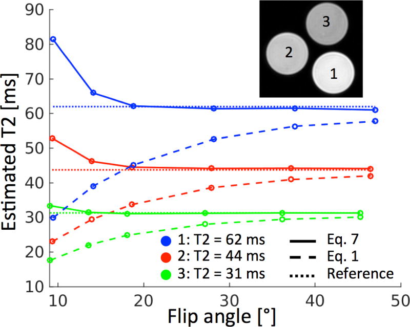
Results from estimating T2 from DESS using Eq. (1) (dashed) and Eq. (7) (solid) as well as from reference FSE scans (dotted). For all phantoms, Eq. (7) clearly agrees better with the reference value than Eq. (1), and for flip angles of 20° or higher, Eq. (7) agrees very well with the reference scans.
4.2 Volunteer scans
Fig. 4 shows the T2 estimates from the DESS scan, using Eqs. (1) and (7), as well as the results from the reference FSE scans and a full numerical fit. The maps from Eq. (7) are more visually similar to the reference scans than those of Eq. (1) (Fig. 4a–c). The RMS difference between the estimates of Eq. (7) and FSE was 3.7 ms, while for Eq. (1) it was 9.6 ms. Plotting the data points from Eq. (7) against the FSE data points and drawing a best fit line that crossed the origin yielded a slope of 0.96, while for Eq. (1) it was 0.77 (Fig. 4f). This demonstrates that Eq. (7) gave T2 estimates that better agreed with FSE estimates than Eq. (1). The full numerical fit gives very similar results to those obtained by Eq. (7), as shown both by its T2 map and by a difference map (scaled by 10), while taking around 60× longer to produce, with an average processing time of 577 s per DESS data set (36×512×512 data points) compared to 9 s for Eq. (7).
Figure 4.
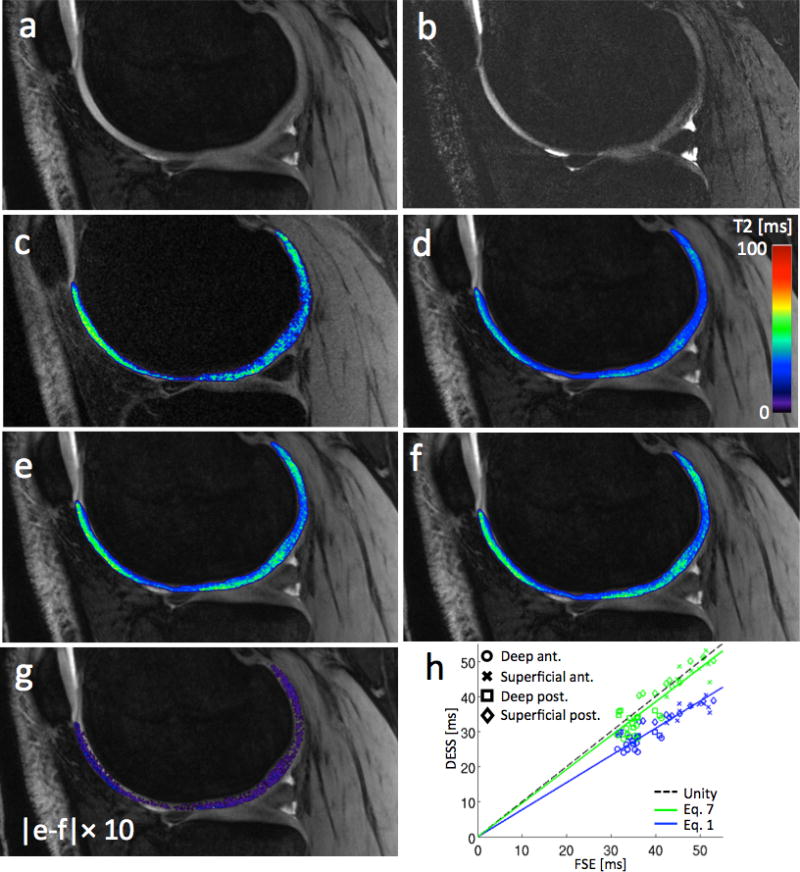
(a) The first echo (S1) from a sample sagittal DESS scan. (b) The second echo (S2) from the same DESS scan. The windowing level is not the same as in panel a, in order to show the cartilage. (c) A sample T2 map from FSE scans of the subject in panels a–b. (d) T2 map of articular cartilage from a the DESS scan in panels a–b using Eq. (1). (e) T2 map using Eq. (7). (f) T2 map using a full numerical fit. The map looks very similar to the one in panel e, but took about 60× longer to produce. (g) A map showing the absolute difference between the maps in panels e and f, multiplied by 10. The difference in the cartilage is small, mostly 1 ms or less. Zero difference appears as transparent. (h) The T2 estimates from 4 regions of femoral cartilage in a total of 10 slices from 3 subjects. The trend line for Eq. (7) (green) better agrees with the FSE scans.
4.3 Patient scans
Fig. 5 shows the scan of a patient with a history of knee injuries and osteochondral defects, visible on the DESS images. Fibrocartilage formation is present in the damaged hyaline cartilage region and in the surrounding subchondral bone. The corresponding region in the DESS T2 map shows a focal decrease in T2 values. In another patient (not shown), the availability of the DESS T2 map made it possible to visualize an oblique meniscal tear in the anterior horn of the medial meniscus, which was challenging to delineate with only the morphological images. In a third patient (not shown), a T2 map acquired with DESS indicated tendinopathy where the patellar tendon had increased T2 values at its insertion site, which was also relatively challenging to visualize with only the morphological DESS images.
Figure 5.
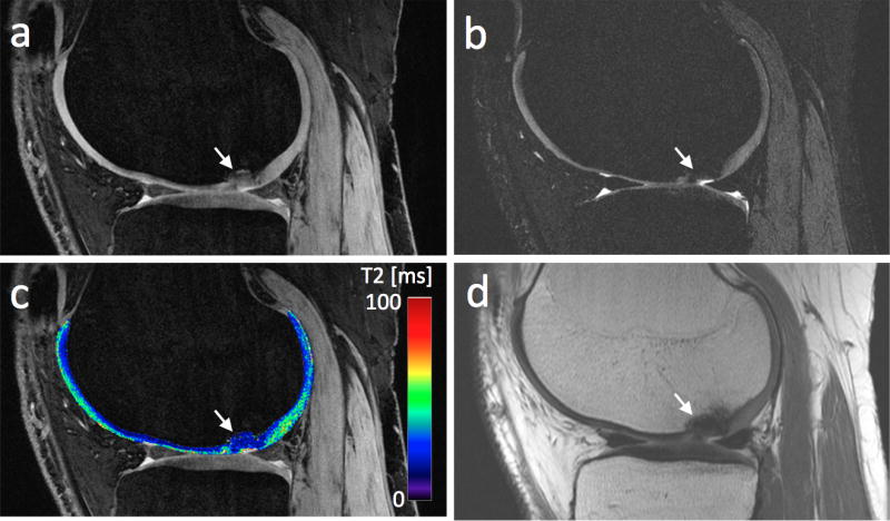
(a) The first echo of a DESS scan of a patient with a chondral lesion (white arrow). (b) The second echo of the DESS scan. Panels a and b both show cartilage signal heterogeneity in the central femoral condyle (note the different windowing settings). (c) The T2 maps resulting from applying Eq. (7) to the data in panels a–b. (d) A PD weighted scan, acquired for reference, shows low signal in the lesion.
5. Discussion
The DESS sequence allows 3D estimation of T2 in cartilage with high SNR efficiency. The signal expressions are complicated, often necessitating imprecise simplifications or time-consuming numerical modeling of the signals. This study explores a linear relationship between the two DESS signals that can be used for accurately estimating T2 from a single scan. We have focused on applying the method in cartilage, but the proposed method could also be used in various other anatomies. This could include T2 mapping in breast cancer patients, which to date is impractical due to the time consuming nature of spin-echo-based T2 measurements [26]. Also, this methodology has been used to perform relaxometry of short-T2 tissues in the knee [27].
The proposed method can be viewed as an extension to Eq. (1), used in ref. [9], that accounts for T1, flip angle, and diffusion. The expression results from applying a similar approximation to that used by Buxton [22], ignoring echo pathways that have spent more than two TRs in the transverse plane. It is important to note, however, that ref. [22] only dealt with sequences acquiring the second echo S2. This required making the assumption that magnetization is transverse for only two TRs from the start of the sequence. In this work, the two-transverse-TR assumption is only applied between the echoes S1 and S2, which is a much weaker assumption, resulting in good performance in spite of a simpler model. Effectively, the model of ref. [22] can be viewed as the model proposed here in the special case of the S1 signal having no transverse history, i.e., being the RF-spoiled or SPGR signal. If S1 in Eq. (6) is replaced with the well-known expression for the RF-spoiled signal, the two models agree (resulting in the same expression for S2).
The scan time for DESS used in this study was about 5 minutes. The patient scans were acquired at a higher resolution than the volunteer scans, but using parallel imaging, the scan time remained at 5 minutes at a cost in SNR. Scan time could be reduced by using lower resolution, higher readout bandwidth, fewer slices, or shorter RF pulses. However, in our experience, a 5 minute scan time is acceptable, especially considering that these 3D scans provide both morphological and quantitative information. Potentially, DESS could replace sagittal FSE scans that are widely used in many current protocols, but this needs to be studied further.
As mentioned, using the linear approximation of Eq. (7) for estimating T2 from a single DESS scan requires an assumed T1 value. This should not lead to large estimation errors, since the method has little sensitivity to T1, which is also not expected to change much in cartilage. For example, using the same scan parameters as for the middle curve in Fig. 2a, with the same assumption of T1 = 1.2 s, yields T2 estimates of 38.8 ms and 41.8 ms (−3.0% and +4.5%) when the real T1 is 0.96 s and 1.44 s (i.e., the actual T1 is 20% lower or higher than the assumed value), respectively. Both values are relatively close to the actual value of 40.0 ms. A correct assumption of T1 = 1.2 s yields T2 = 40.6 ms (+1.5%), a slight overestimate due to the approximation made. Similarly, sensitivity to B1 results in estimates of 36.9 ms and 43.1 ms (−7.75% and +7.75%) when the actual flip angle α is 20° and 30° (i.e., 20% lower or higher than the assumed value of 25°). The B1 sensitivity could be mitigated by acquiring a B1 map along with the DESS scan. The sensitivity of the T2 estimate to errors in the T1 and α assumptions is further demonstrated in Fig. 6. It should also be noted that assumptions of T1 and flip angle will always be needed when estimating T2 from a single DESS scan, regardless of the model used.
Figure 6.
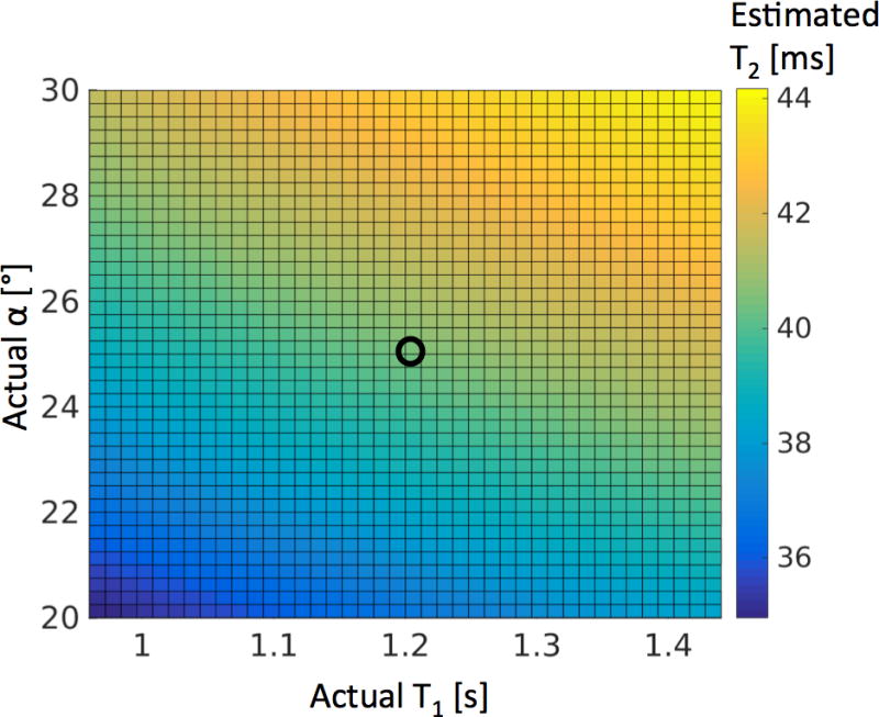
The sensitivity of the T2 estimation method in Eq. (7) to errors in the assumption of T1 and B1. The true T2 is 40 ms. The flip angle α and T1 are assumed to be 25° and 1.2 s, but actually vary from these values by +/− 20%. Other scan parameters were the same as in Fig. 2a. The black circle shows the point where the assumptions of α and T1 are correct.
The proposed method can also be used in combination with other methods for quantitative DESS imaging. Cheng et al. proposed a multi-echo DESS sequence for imaging T2 and T2* that measures S1 and S2 at different echo times and uses the fact that T2′ causes dephasing of S1 and rephasing of S2 [28]. Put together, the two methods could potentially estimate other parameters such as T1 or flip angle. Also, it has previously been noted by Bieri et al. that the ratio (S2HS1L)/(S1HS2L), where H and L denote scans with a large and small (Δk ≈ 0) spoiler gradient moment, respectively, has good diffusion sensitivity but low sensitivity to T1 and T2 [11]. This is consistent with the expression derived from Eq. (6):
| (16) |
This relationship is independent of T2, and largely insensitive to T1.
In conclusion, we have demonstrated a simplified expression for the ratio between the DESS signals, providing good T2 estimation. The expression disregards higher-order echo pathways, an assumption we have shown to be valid due to both decay and cancellation of such pathways. The expression takes into account signal dependency to T1 and flip angle, and we have shown that the method works well by assuming a T1 typical for the tissue and using the prescribed flip angle in calculations.
Highlights.
A simple method for estimating T2 from a single DESS scan is proposed
The method gave good results in simulations and in phantoms and in vivo scans
Easy implementation and fast processing allow for near-instant T2 maps at scanner
Acknowledgments
This study was supported by National Institutes of Health (NIH) P41 EB015891, R01 AR063643, and R01 EB002524 and by GE Healthcare.
Footnotes
Publisher's Disclaimer: This is a PDF file of an unedited manuscript that has been accepted for publication. As a service to our customers we are providing this early version of the manuscript. The manuscript will undergo copyediting, typesetting, and review of the resulting proof before it is published in its final citable form. Please note that during the production process errors may be discovered which could affect the content, and all legal disclaimers that apply to the journal pertain.
References
- 1.Bruder H, Fischer H, Graumann R, Deimling M. A New Steady-State Imaging Sequence for Simultaneous Acquisition of Two MR Images with Clearly Different Contrasts. Magnetic Resonance in Medicine. 1988;7:35–42. doi: 10.1002/mrm.1910070105. [DOI] [PubMed] [Google Scholar]
- 2.Redpath TW, Jones RA. FADE - A New Fast Imaging Sequence. Magnetic Resonance in Medicine. 1988;6:224–234. doi: 10.1002/mrm.1910060211. [DOI] [PubMed] [Google Scholar]
- 3.Lee SY, Cho ZH. Fast SSFP Gradient Echo Sequence for Simultaneous Acquisitions of FID and Echo Signals. Magnetic Resonance in Medicine. 1988;8:142–150. doi: 10.1002/mrm.1910080204. [DOI] [PubMed] [Google Scholar]
- 4.Moran CJ, Saranathan M, Nnewihe AN, Granlund KL, Alley MT, Daniel BL, Hargreaves BA. High resolution images of the breast. European Journal of Radiology. 2012;81S1:S101–S103. doi: 10.1016/S0720-048X(12)70041-4. [DOI] [PubMed] [Google Scholar]
- 5.Granlund KL, Staroswiecki E, Alley MT, Daniel BL, Hargreaves BA. High-resolution, three-dimensional diffusion-weighted breast imaging using DESS. Magnetic Resonance Imaging. 2014;32:330–341. doi: 10.1016/j.mri.2013.12.014. [DOI] [PMC free article] [PubMed] [Google Scholar]
- 6.Ikonen S, Kärkkäinen P, Kivisaari L, Salo JO, Taari K, Vehmas T, Tervahartiala P, Rannikko S. Endorectal magnetic resonance imaging of prostatic cancer: comparison between fat-suppressed T2-weighted fast spin echo and three-dimensional dual-echo, steady-state sequences. European Radiology. 2011;11(2):236–241. doi: 10.1007/s003300000598. [DOI] [PubMed] [Google Scholar]
- 7.Dregely I, Margolis DAJ, Sung K, Zhou Z, Rangwala N, Raman SS, Wu HH. Rapid Quantitative T2 Mapping of the Prostate Using Three-Dimensional Dual Echo Steady State MRI at 3T. Magnetic Resonance in Medicine. 2016 doi: 10.1002/mrm.26053. [DOI] [PubMed] [Google Scholar]
- 8.Peterfy CG, Schneider E, Nevitt M. The osteoarthritis initiative: report on the design rationale for the magnetic resonance imaging protocol for the knee. Osteoarthritis and Cartilage. 2008;16:1433–1441. doi: 10.1016/j.joca.2008.06.016. [DOI] [PMC free article] [PubMed] [Google Scholar]
- 9.Welsch GH, Scheffler K, Mamisch TC, Hughes T, Millington S, Deimling M, Trattnig S. Rapid Estimation of Cartilage T2 Based on Double Echo at Steady State (DESS) With 3 Tesla. Magnetic Resonance in Medicine. 2009;62:544–549. doi: 10.1002/mrm.22036. [DOI] [PubMed] [Google Scholar]
- 10.Staroswiecki E, Granlund KL, Alley MT, Gold GE, Hargreaves BA. Simultaneous Estimation of T2 and Apparent Diffusion Coefficient in Human Articular Cartilage In Vivo with a Modified Three-Dimensional Double Echo Steady State (DESS) Sequence at 3 T. Magnetic Resonance in Medicine. 2012;67:1086–1096. doi: 10.1002/mrm.23090. [DOI] [PMC free article] [PubMed] [Google Scholar]
- 11.Bieri O, Ganter C, Scheffler K. Quantitative In Vivo Diffusion Imaging of Cartilage Using Double Echo Steady-State Free Precession. Magnetic Resonance in Medicine. 2012;68:720–729. doi: 10.1002/mrm.23275. [DOI] [PubMed] [Google Scholar]
- 12.Heule R, Ganter C, Bieri O. Rapid Estimation of Cartilage T2 with Reduced T1 Sensitivity Using Double Echo Steady State Imaging. Magnetic Resonance in Medicine. 2014;71:1137–1143. doi: 10.1002/mrm.24748. [DOI] [PubMed] [Google Scholar]
- 13.Mosher TJ, Dardzinski BJ. Cartilage MRI T2 relaxation time mapping: overview and applications. Seminars in Musculoskeletal Radiology. 2004;8(4):355–368. doi: 10.1055/s-2004-861764. [DOI] [PubMed] [Google Scholar]
- 14.Raya JG, Melkus G, Adam-Neumair S, Dietrich O, Mützel E, Kahr B, Reiser MF, Jakob PM, Putz R, Glaser C. Change of Diffusion Tensor Imaging Parameters in Articular Cartilage With Progressive Proteoglycan Extraction. Investigative Radiology. 2011;46(6):401–409. doi: 10.1097/RLI.0b013e3182145aa8. [DOI] [PubMed] [Google Scholar]
- 15.Wu EX, Buxton RB. Effect of Diffusion on the Steady-State Magnetization with Pulsed Field Gradients. Journal of Magnetic Resonance. 1990;90:243–253. [Google Scholar]
- 16.Freed DE, Scheven UM, Zielinski LJ, Sen PN, Hürlimann MD. Steady-state free precession experiments and exact treatment of diffusion in a uniform gradient. Journal of Chemical Physics. 2001;115(9):4249–4258. [Google Scholar]
- 17.Weigel M, Schwenk S, Kiselev VG, Scheffler K, Hennig J. Extended phase graphs with anisotropic diffusion. Journal of Magnetic Resonance. 2010;205:276–285. doi: 10.1016/j.jmr.2010.05.011. [DOI] [PubMed] [Google Scholar]
- 18.Scheffler K. A Pictorial Description of Steady-States in Rapid Magnetic Resonance Imaging. Concepts in Magnetic Resonance. 1999;11(5):291–304. [Google Scholar]
- 19.Kaiser R, Bartholdi E, Ernst RR. Diffusion and field-gradient effects in NMR Fourier spectroscopy. The Journal of Chemical Physics. 1974;60(8):2966–2979. [Google Scholar]
- 20.Hennig J. Multiecho Imaging Sequences with Low Refocusing Flip Angles. Journal of Magnetic Resonance. 1988;78:397–407. [Google Scholar]
- 21.Weigel M. Extended Phase Graphs: Dephasing, RF Pulses, and Echoes - Pure and Simple. Journal of Magnetic Resonance Imaging. 2015;41:266–295. doi: 10.1002/jmri.24619. [DOI] [PubMed] [Google Scholar]
- 22.Buxton RB. The Diffusion Sensitivity of Fast Steady-State Free Precession Imaging. Magnetic Resonance in Medicine. 1993;29:235–243. doi: 10.1002/mrm.1910290212. [DOI] [PubMed] [Google Scholar]
- 23.Gold GE, Han E, Stainsby J, Wright G, Brittain J, Beaulieu C. Musculoskeletal MRI at 3.0 T: Relaxation Times and Image Contrast. American Journal of Roentgenology. 2004;183(2):343–351. doi: 10.2214/ajr.183.2.1830343. [DOI] [PubMed] [Google Scholar]
- 24.Liu JV, Bock NA, Silva AC. Rapid high-resolution three-dimensional mapping of T1 and age-dependent variations in the non-human primate brain using magnetization-prepared rapid gradient-echo (MPRAGE) sequence. NeuroImage. 2011;56:1154–1163. doi: 10.1016/j.neuroimage.2011.02.075. [DOI] [PMC free article] [PubMed] [Google Scholar]
- 25.Sacolick LI, Wiesinger F, Hancu I, Vogel MW. B1 Mapping by Bloch-Siegert Shift. Magnetic Resonance in Medicine. 2010;63:1315–1322. doi: 10.1002/mrm.22357. [DOI] [PMC free article] [PubMed] [Google Scholar]
- 26.Moran CJ, Granlund KL, Daniel BD, Sveinsson B, Staroswiecki E, Alley MT, Hargreaves BA. Dual Echo Steady State Quantitative T2-Mapping in the Breast. Proc 20th Annual Meeting ISMRM; 2012; Melbourne. p. 1490. [Google Scholar]
- 27.Chaudhari AS, Sveinsson B, Moran CJ, McWalter EJ, Johnson EM, Zhang T, Gold GE, Hargreaves BA. Imaging and T2 relaxometry of short-T2 connective tissues in the knee using ultrashort echo-time double-echo steady-state (UTEDESS) Magn Reson Med. 2016 doi: 10.1002/mrm.26577. http://dx.doi.org/10.1002/mrm.26577. [DOI] [PMC free article] [PubMed]
- 28.Cheng CC, Mei CS, Duryea J, Chung HW, Chao TC, Panych LP, Madore B. Dual-pathway multi-echo sequence for simulataneous frequency and T2 mapping. Journal of Magnetic Resonance. 2016;265:177–187. doi: 10.1016/j.jmr.2016.01.019. [DOI] [PMC free article] [PubMed] [Google Scholar]


