

Abstract
Ultralight cellular sponges offer a unique set of properties. We show here that solvent uptake by these sponges results in new gel‐like materials, which we term spongy gels. The appearance of the spongy gels is very similar to classic organogels. Usually, organogels are formed by a bottom‐up process. In contrast, the spongy gels are formed by a top‐down approach that offers numerous advantages for the design of their properties, reproducibility, and stability. The sponges themselves represent the scaffold of a gel that could be filled with a solvent, and thereby form a mechanically stable gel‐like material. The spongy gels are independent of a time‐consuming or otherwise demanding in situ scaffold formation. As solvent evaporation from gels is a concern for various applications, we also studied solvent evaporation of wetting and non‐wetting liquids dispersed in the sponge.
Keywords: electrospinning, gels, sponges
Ultralight‐weight scaffolds with open cell fibrous structures are known for a variety of materials prepared by different methods.1 One of the most common methods is the use of a dispersion of a solid scaffold material in a solution followed by a freeze‐drying step.2 This method has also been successfully used recently for dispersions of short electrospun polymer fibers.3 The resulting polymer scaffolds are termed as aerogels or sponges. In contrast to classic aerogels, the sponges are made directly from fibers and not from gels. The solid scaffold of the sponges is pre‐formed by electrospun fibers, while the shape and dimension of the solid scaffold of the aerogel is formed during the gelation process. Typically, the sponges made from electrospun fibers have very low densities (10 mg cm−3) and show very high porosities (>99.5 %) like classic aerogels, but much larger pore size in the range of several 10 μm, while aerogels are mostly mesoporous.3a, 4 The sponges are water‐repelling but oleophilic, which makes them perfect materials for membranes for separation of organic compounds (such as oil or organic solvents) from water.3a,3e, 5 An amazing feature of these sponges is the absorption of huge amounts of oily liquids while keeping their shape, in spite of a tiny mass of the solid scaffold of the sponges.3a,3b The huge capacity can be understood by the large pore volume of 200–300 mL g−1 of the sponges derived from their densities. With a liquid of a density of 1 g cm−3, 30 mg of polymer spongy scaffold (Figure 1 a) keeps 30 g of liquid in a shape that is 1000‐times the mass of the spongy scaffold. The appearance of the sponge/liquid mixture after uptake of the liquid is gel‐like (Figure 1 b). This type of gel‐like material represents a new paradigm for gels and is defined here as spongy gels. Essentially, the mixture shows all of the characteristics of a thixotropic gel: a liquid phase, a 3D network, and practically no flow.
Figure 1.

Sponge made of electrospun fibers with mass of 0.03 g (a) and the sponge after uptake of 30 g of mineral oil (b).
A similar relation, but in a reverse fashion, can be found in the so‐called organogels (also referred to as molecular gels), which consist of a solid self‐assembled 3D fibrous network (in some cases it could be also platelets) and a nonpolar liquid.4, 6 Organogels are formed by self‐assembly of an organogelator to an entangled fibrous 3D network in a nonpolar liquid (Figure 2 a). The self‐assembly process could be initiated by different stimuli, such as temperature, concentration, pH, light, and current. The organogelators can possess different chemical nature ranging from low‐molecular weight to polymer organogelators, and even coordination compounds. The chemical nature of the organogelators and apolar liquid could lead to a variety of different applications including drug delivery, sensors, lubrication, templates, oil recovery, and optical media.4, 6 An important feature for drug delivery applications of organogels is that they are thermodynamically stable but could also disintegrate under certain conditions. Similar to spongy gels, organogels are thixotropic gels from the rheological point of view. Spongy gels obtained by contact of electrospun sponges with organic liquids show essentially the same features as an organogel: the formation of a 3D fibrous network, commonly assigned as self‐assembled fibrillary network, filled with an apolar liquid. Even the disintegration of spongy gels is possible as reported previously.3b In contrast to organogels, the 3D fibrous network of spongy gels is pre‐formed and then filled with the apolar liquid (Figure 2 b). To avoid any misunderstanding or confusion of scientific terminology, it should be emphasized here that spongy gels are not organogels, as organogels are based on self‐assembly of low‐ or high‐molecular weight molecules,4, 6 while spongy gels are based on fibrous scaffolds. The appearance of organogels and spongy gels are very similar, but the spongy gels have the distinct advantages of fine control over the nature and structure of the 3D fibrous network, no shrinkage, no sensitivity to impurities on gel formation, and provide a wide range of possibilities for functionalization owing to the wealth of modifications of electrospun fibers. Although a wide variety of beautiful examples for the functionalization of organogels has been shown, their realization is often laborious, in particular as far as the synthesis of the organgelators is concerned, which makes organogels quite expensive.4, 7 Another disadvantage of organogels is their sensitivity to impurities in conjunction with the gelation process, which hampers technical applications.4, 7 With this set of differences, spongy gels offer completely new possibilities but also raise several questions that we want to discuss in this paper. We report here on the preparation of spongy gels by a top‐down process. We obtained the spongy gels by filling of macroporous ultralight polymer sponges with wetting and non‐wetting liquid. We show that spongy gels behave in many respects similar to organogels. It is important to note that the sponges used here were made from dispersions of short electrospun fibers that can disintegrate upon contact with solvents. As recently shown, the sponges could be stabilized by an additional conformal coating by poly(p‐xylylene) (PPX) by deposition from the vapor phase.3b This PPX coating makes the sponges highly stable against solvents, which enables the formation of gels according to Figure 2 b. To gain understanding of organogels based on spongy gels, we discuss here the mechanical properties of the spongy gels and the evaporation of wetting and non‐wetting liquids from the spongy gels backed by theoretical considerations.
Figure 2.
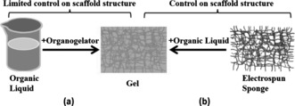
Drawing of the formation of organogels by action of organogelators on liquids (a) and by filling of electrospun fiber sponges with liquids (b).
The PPX‐coated sponges under investigation were made according to a previously published procedure with densities of 16.2 (P‐SG1) and 30.6 (P‐SG2) mg cm−3, respectively.3b The cross‐section morphologies of the sponges showed for P‐SG1 much higher pore size than those of P‐SG2 (Figure 3). The differences in the density and the pore size lead to the different porosity (P), which was determined according to Equation (1).
| (1) |
Figure 3.
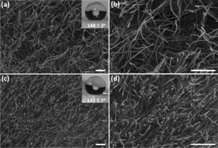
Cross‐section morphology of the P‐SG1 (a, b) and P‐SG2 (c, d). Scale bar: 100 μm. Insert of (a) and (c) are the water contact angle of the corresponding sponges.
Herein, ρ SG and ρ bulk are the density of the sponges and the corresponding bulk density, respectively. The bulk densities for the P‐SG1 and P‐SG2 are 953 and 1457 mg cm−3, respectively. The calculated corresponding porosities for the P‐SG1 and P‐SG2 are 98.3 % and 97.9 %, respectively, which are slightly smaller than the porosity (99.5 %) of the original fibrous sponges due to the additional PPX coating.
The sponges P‐SG1 and P‐SG2 were hydrophobic, with water contact angles (WCA) of 148±3° and 142±2°, respectively. Consequently, water is a non‐wetting liquid for both sponges. In contrast, ethanol is a wetting liquid for the sponges, with contact angles of 0° (Supporting Information).
For a variety of applications, the evaporation behavior of liquids from the sponges could be of major importance. Therefore, we investigated the evaporation of different liquids and differentiated between wetting and non‐wetting liquids, sponges of different densities, and methods of liquid delivery into the sponges. The evaporation of a wetting liquid from the sponges was analyzed with ethanol while water was used as a non‐wetting liquid. The results clearly showed that the evaporation was very similar, with ethanol, for the sponges P‐SG1 and P‐SG2 with different densities (Figure 4). The evaporation was also independent of the sponge density for ethanol injected into the sponge and water, but the evaporation rate differed significantly for the wetting and non‐wetting liquid that could not be only due to the different vapor pressures of ethanol and water. Therefore, we developed a model for the evaporation of ethanol and water from spongy gels.
Figure 4.
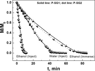
Evaporation of ethanol and water from P‐SG1 and P‐SG2.
The so‐called d2‐law for spherical drop evaporation predicts that the drop diameter d decreases linearly in time.8 Accordingly, the drop volume and thus its mass decreases in time as per Equation (2).
| (2) |
Herein, B=(c w−c ∞)/(ρ av−c w) is the Spalding number, M is the current mass of water in the sample, M 0 is the initial mass of liquid in the sample, a 0 is the initial radius (or a characteristic length) of liquid body, D is the diffusion coefficient of the liquid vapor in air, c w is the saturated liquid vapor concentration over the liquid surface (depending on surface temperature T s), c ∞ is the liquid vapor concentration in air determined by humidity, ρ av is the density of the air–vapor mixture, ρ is the liquid density, and t is time.
For liquid evaporation in air at room temperature, as in the present case, the vapor concentration is small, which implies that (c w−c ∞)≪ρ av and c w≪ρ av . Then, the Spalding number B≪1, which means that the Stefan flow is negligibly small and vapor diffusion is dominant compared to the convective transport. Therefore, Equation (2) reduces to Equation (3).
| (3) |
The surface temperature of evaporating levitating droplets can be calculated quite accurately.9 However, in the present case, the sponge with the evaporating liquid was supported by a metal holder, which inevitably increased the droplet surface temperature due to the high thermal conductivity of metal. Therefore, when calculating the saturated liquid vapor concentration over the liquid surface, the surface temperature T s was taken as the values listed in the caption to Figure 5, which illustrates the comparisons of the predictions of [Eq. (2)] for the four experimental cases. Two panels in Figure 5 a and 5 b correspond to evaporation of a non‐wettable liquid (water) from the sponge, while two other panels (Figure 5 c and 5 d) correspond to evaporation of a wettable liquid (ethanol). In all of the cases, [Eq. (3)] describes the data quite accurately, which ascertains that liquid evaporating from sponge can always be considered as a shrinking‐in‐time blob. Note also that sample porosities are of the order of ϵ=0.9. The diffusion coefficient D decreases with porosity ϵ as D=D 0 ϵ 4/3, where D 0 is the value of the vapor diffusion coefficient in open space (ϵ=1).10 Because the sample porosity is at least ϵ=0.9, the presence of the sponge structure practically does not restrict diffusion of vapor molecules, and accordingly, the value of the diffusion coefficient D can be taken approximately as D 0.
Figure 5.
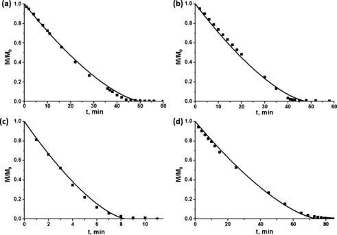
Evaporation from the sponges. a) Non‐wettable sponge, 7.57 mg of water; T s=12 °C. b) Non‐wettable sponge, 6.38 mg of water; T s=11 °C. c) Wettable sponge, 4.2 mg of ethanol; T s=12 °C. d) Wettable sponge, 190.66 mg of ethanol; T s=18 °C. In all of the cases, the humidity was assumed to be zero.
Gels are liquid/solid mixtures that show essentially no flow but should display a larger storage modulus G′ than a loss modulus G′′. Dynamic oscillatory shear experiments were carried out with P‐SG2 in gel state filled with ethylene glycol (Figure 6). The strain sweep test for P‐SG2 filled with ethylene glycol is shown in Figure 6 a. The storage modulus is almost constant at low strains and shows a clear decrease at strains higher than 1 %, whereas G′′ shows an increase up to 2 % strain. G′ is higher than G′′ in the entire range that has been investigated. For the following measurements (frequency sweep and temperature sweep), a strain of 0.2 % was chosen to ensure that the deformation is within the linear regime. Similar measurements have already been performed on hydrogels in the literature.11 In Figure 6 b, the temperature‐dependent behavior of the materials shows a much higher storage modulus than the loss modulus over the entire temperature range. This indicates a highly elastic behavior of the material, which is typical for a gel. The frequency tests of the materials at 25 °C and 50 °C can be found in Figure 6 c and 6 d. The elastic modulus is almost constant and much higher than the storage modulus over the entire frequency range, which is another characteristic gel behavior.
Figure 6.

Dynamic oscillatory shear rheological properties of P‐SG2 gel loaded with ethylene glycol as functions of strain (a), temperature (b), and frequency at 25 (c) and 50 °C (d).
The rheological measurements of the dry sponges can be found in the Supporting Information (Figure S2). The behavior of the dry materials is in general very similar to the ones filled with ethylene glycol. The decrease in storage modulus at higher strains and higher temperatures is, however, a little less pronounced in the dry materials. The loss modulus in all the measurements is lower for the dry materials. This indicates a lower plastic deformation of the dry materials compared to the ethylene‐glycol‐filled ones.
In conclusion, ultraporous fibrous polymer sponges with tunable porosity and density have been successfully applied to load organic solvents for the formation of spongy gels. These spongy gels was mechanically stable and presented similar rheological behavior to classic organogels. The evaporation behavior of nonwettable and wettable solvents from the spongy gels are successfully described by the d2 evaporation model, and the evaporation of both solvents could be considered as shrinking‐in‐time blobs. These spongy gels could find potential applications in drug delivery, bioengineering, catalysts, sensors, lubrication, templates, oil recovery, and optical media, which makes them of particular interest for future materials development.
Conflict of interest
The authors declare no conflict of interest.
Acknowledgements
We acknowledge financial support from the Deutsche Forschungsgemeinschaft (DFG, SFB 840).
S. Jiang, G. Duan, U. Kuhn, M. Mörl, V. Altstädt, A. L. Yarin, A. Greiner, Angew. Chem. Int. Ed. 2017, 56, 3285.
Contributor Information
Prof. Alexander L. Yarin, Email: ayarin@uic.edu
Prof. Andreas Greiner, Email: greiner@uni-bayreuth.de
References
- 1.
- 1a. Hollister S. J., Nat. Mater. 2005, 4, 518–524; [DOI] [PubMed] [Google Scholar]
- 1b. Moutos F. T., Freed L. E., Guilak F., Nat. Mater. 2007, 6, 162–167; [DOI] [PubMed] [Google Scholar]
- 1c. Loh Q. L., Choong C., Tissue Eng. Part B 2013, 19, 485–502. [DOI] [PMC free article] [PubMed] [Google Scholar]
- 2.
- 2a. Wu J., Meredith J. C., ACS Macro Lett. 2014, 3, 185–190; [DOI] [PubMed] [Google Scholar]
- 2b. Kim M. Y., Lee J., Carbohydr. Polym. 2011, 84, 1329–1336; [Google Scholar]
- 2c. Qian L., Zhang H., J. Chem. Technol. Biotechnol. 2011, 86, 172–184. [Google Scholar]
- 3.
- 3a. Duan G., Jiang S., Jérôme V., Wendorff J. H., Fathi A., Uhm J., Altstädt V., Herling M., Breu J., Freitag R., Adv. Funct. Mater. 2015, 25, 2850–2856; [Google Scholar]
- 3b. Duan G., Jiang S., Moss T., Agarwal S., Greiner A., Polym. Chem. 2016, 7, 2759–2764; [Google Scholar]
- 3c. Xu T., Miszuk J. M., Zhao Y., Sun H., Fong H., Adv. Healthcare Mater. 2015, 4, 2238–2246; [DOI] [PubMed] [Google Scholar]
- 3d. Chen W., Ma J., Zhu L., Morsi Y., Ei-Hamshary H., Al-Deyab S. S., Mo X., Colloids Surf. B 2016, 142, 165–172; [DOI] [PubMed] [Google Scholar]
- 3e. Si Y., Yu J., Tang X., Ge J., Ding B., Nat. Commun. 2014, 5, 5802. [DOI] [PubMed] [Google Scholar]
- 4. Weiss R. G., J. Am. Chem. Soc. 2014, 136, 7519–7530. [DOI] [PubMed] [Google Scholar]
- 5. Si Y., Fu Q., Wang X., Zhu J., Yu J., Sun G., Ding B., ACS Nano 2015, 9, 3791–3799. [DOI] [PubMed] [Google Scholar]
- 6. Ajay Mallia V., Weiss R. G., Soft Matter 2016, 12, 3665–3676. [DOI] [PubMed] [Google Scholar]
- 7. Abdallah D. J., Weiss R. G., Adv. Mater. 2000, 12, 1237–1247. [Google Scholar]
- 8.
- 8a. Yarin L. P., Hetsroni G., Combustion of Two-phase Reactive Media, Springer Science & Business Media, Berlin, 2004; [Google Scholar]
- 8b. Sirignano W. A., Fluid Dynamics and Transport of Droplets and Sprays, Cambridge University Press, Cambridge, 2010. [Google Scholar]
- 9. Yarin A. L., Brenn G., Kastner O., Rensink D., Tropea C., J. Fluid Mech. 1999, 399, 151–204. [Google Scholar]
- 10. Davidson E. A., Trumbore S. E., Tellus Ser. B 1995, 47, 550–565. [Google Scholar]
- 11. Liu F., Seuring J., Agarwal S., Macromol. Chem. Phys. 2014, 215, 1466–1472. [Google Scholar]