Abstract
Computer-assisted orthopaedic surgery was born in the 1990s. Nowadays, computer-assisted orthopaedic surgery is used for transpedicular screw fixation and for total knee arthroplasty.
Patient-specific instrumentation is one type of computer-assisted surgery based on volumetric images, such as computed tomography or magnetic resonance imaging.
In this article, possible applications of patient-specific instruments in paediatric orthopaedics are described. The use of patient-specific instrumentation for the correction of cubitus varus is given as an example with complex osteotomy. Another application for tarsal coalition resection is shown.
A last example of using patient-specific instrumentation for both tumour resection and allograft reconstruction is illustrated.
Patient-specific instruments based on computed tomography of the bone can increase peri-operative accuracy and decrease operative time. They are very helpful for the surgeon. Other applications are possible and will be probably developed in the future.
Cite this article: Docquier PL, Paul L, TranDuy V. Surgical navigation in paediatric orthopaedics. EFORT Open Rev 2016;1:152-159. DOI: 10.1302/2058-5241.1.000009.
Keywords: surgical navigation, paediatrics, patient-specific instrumentation, corrective osteotomy, foot correction, tumour resection
Computer-assisted surgery (CAS) is the term used to describe the concept of applying computers to enable pre-operative planning and provide intra-operative assistance or guidance. CAS is also known as computer-aided surgery, computer-assisted intervention, image-guided surgery and surgical navigation. CAS applied to orthopaedic surgery is termed ‘computer-assisted orthopaedic surgery’ (CAOS). The first rudimental CAS systems were developed in the early 1970s. These systems gave feedback on instrument positioning in stereotaxic neurosurgery.1 In orthopaedic surgery, the first CAOS application was in 1995 for transpedicular screw fixation in the spine.2 In orthopaedic oncology, the first reported application was for pelvic sarcoma resection in 20043 and the first use for both sarcoma resection and reconstruction with an allograft was in 2010.4 In paediatric orthopaedic surgery, CAOS systems have been developed for complex osteotomies,5 for tumour resection6,7 and for tarsal coalition resection.8
Navigation and robotic systems are the most advanced parts of CAOS.9 Surgical navigation is a visualisation system that gives positional information about surgical tools or implants relative to a target organ (bone). There are three types of surgical navigation systems:
Volumetric image-based navigation uses volumetric images, such as computed tomography (CT), magnetic resonance imaging (MRI), or ultrasound echograms (US). These modalities are most often used to extract bone surface.
Fluoroscopic navigation makes use of intra-operative fluoroscopic images to reconstruct a three-dimensional (3D) model of the bone.
Imageless navigation makes use of kinetic information about joints or morphometric information regarding the target bones obtained intra-operatively.
There are three types of robotic systems developed to overcome the inaccuracy of hand-controlled positioning of surgical tools:9
The first type locates a cutting guide block or a drilling guide sleeve to allow the surgeon to slide a bone saw or a drill bit into the guide.
Another type constrains the range of movement of a surgical tool held by a robot arm.
The last type is an active system which directs a milling device automatically, according to pre-operative planning.
Patient-specific instrument (PSI)
PSI is a single-use instrument specific to each patient. The concept of patient-specific templates was introduced in the 1990s by Radermacher et al10 for pedicle screw placement, total knee arthroplasty, decompression of the cervical spine and triple osteotomy of the pelvis. Several weeks prior to surgery, a CT or a MRI scan is taken of the patient’s bone. Using a manufacturer-specific protocol, the surgeon sends the scan and preliminary surgical preferences to the manufacturer. An engineer processes the data to identify specific anatomical landmarks and creates a computer-generated, customised surgical plan. Once the surgeon approves the plan, a corresponding set of disposable cutting blocks or pin guides is manufactured to help the surgeon in the positioning and alignment tasks of the surgical tool. The goal is to correctly position the implant during surgery. Salako et al used guided intrapedicular screws to decrease the rate of misplaced screws.11 Leiggener et al12 manufactured a guide by additive manufacturing using selective laser sintering (SLS) for mandible reconstruction with free fibula osseous flap. They were able to perform a complex reconstruction by choosing the best position on the donor (fibula) and recipient (mandible) sites, avoiding important structures like dental nerve and respecting vascular anatomy. Modabber et al13 have concluded that this technique significantly decreased the shaping time during surgery, and should in addition have an impact on the survival of the flap.
Advantages of CAOS
The principal idea behind CAOS is that operative outcomes will be improved through the use of computer technology. CAOS helps the surgeon to more accurately pinpoint anatomical landmarks, and guides the surgeon through different bone cuts. Three main advantages of CAOS and PSIs have been found. PSIs have been widely tested to assess their accuracy and impact on time during the surgery. The early reported results on accuracy of PSIs were encouraging. Positioning measurements have shown angulation error below 0.6° in the spine and the tibia and 1° in the femur.14 Cadaveric experiments showed clinically acceptable results in the spine15 with few errors above 2 mm when compared with the conventional method. On the question of time, studies have shown a shorter duration of surgery by using PSIs in three different applications. This improvement is easily understandable because of the ‘plug and play’ characteristic of the instrument. The user places the instrument in the correct position and connects standard devices to achieve the desired task. A cadaveric experiment has demonstrated that PSIs decreased the time to find the entry point for drilling in a vertebra pedicle.15 For triple pelvic osteotomies on actual patients, the whole surgery time decreased by 23%, to gain 35 minutes.16 The decrease of intra-operative irradiation thanks to a lesser use of fluoroscopy is also an added value of the technology. It has been shown that it is significantly decreased when using PSIs.17
In this report we will demonstrate the use of PSI technology in paediatric orthopaedics by describing three possible clinical applications.
Application for complex osteotomies
A non-anatomical bone malunion or a congenital malformation can limit the leg function or give a poor aesthetic appearance. When the limitation interferes with normal everyday life, corrective surgery is indicated. The required correction is often a complex bi-planar bone section. Using a conventional manual method, the obtained correction is often sub-optimal, leading to an over- or under-correction. A 3D simulation of the levels of bone section is very helpful to visualise the initial position and estimate the appropriate correction.
Cubitus varus
Cubitus varus is a good example of a complex 3D deformity in children. Malunion in cubitus varus most often occurs resulting from inadequate reduction of a supracondylar fracture of the humerus. Cubitus varus does not always impair elbow function or elbow range of motion, but the cosmetic deformity may lead parents to request an operation to improve the appearance of the elbow. Planning based on conventional radiology may be a source of inaccuracy because of important errors in the angular measurement.18 During the surgery, it is very difficult to orientate the saw blade correctly. Accurate correction of a cubitus varus needs to take into account the deformity in three dimensions and not only in the frontal and sagittal projections, in order to obtain a good result in terms of appearance and function.19
Pre-operative 3D-planning and PSI
A pre-operative humerus CT scan is obtained with a minimal resolution of 1 mm spacing between slices and 2 mm slice thickness. A 3D reconstruction of the bone is made from the CT scan. The varus deformity and the flexion or extension deformity are assessed on the 3D reconstruction of the distal humerus. The closing wedge is planned according to frontal/sagittal angle measurement. The transverse rotation plane is corrected as well to restore an optimal joint line (Fig. 1). No bony hinge is left at the opposite side in order to medially translate the distal fragment and decrease the residual condylar prominence (Fig. 2).
Fig. 1.
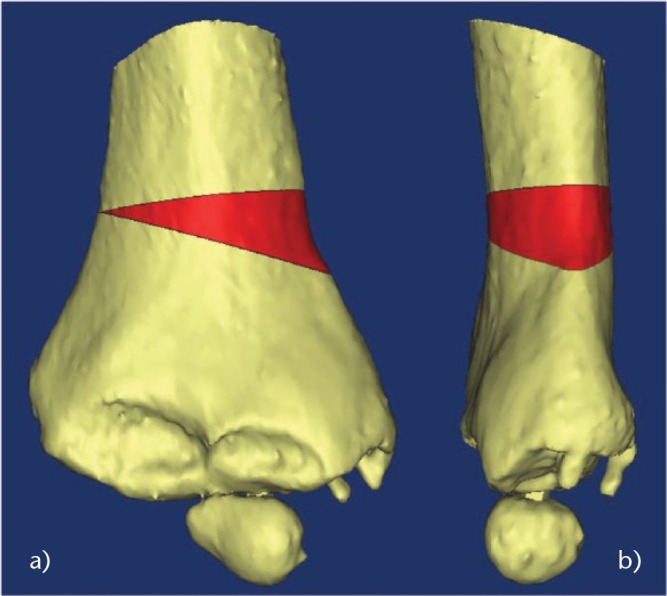
Images showing the planning of the closing wedge (in red) to correct both a) frontal and b) sagittal planes.
Fig. 2.
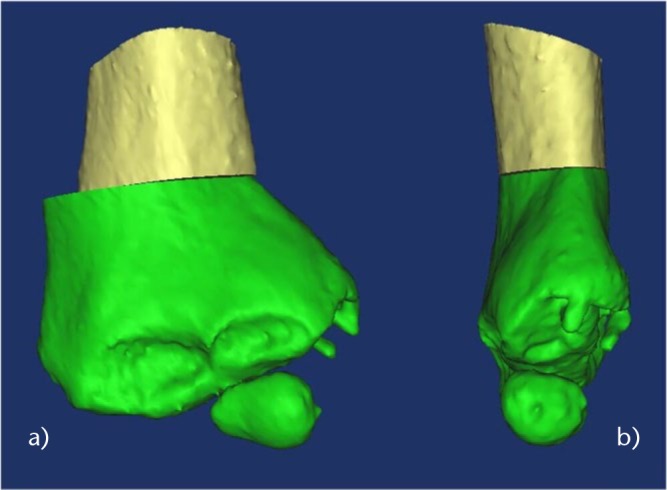
Images showing that no hinge is left at the opposite side to allow medialisation of the distal fragment in the a) frontal and b) sagittal planes.
The PSI is designed based on the 3D computer simulation and is manufactured using a biocompatible material (polyamide) by SLS. The PSI consists of three different parts:
A first main PSI to place four 2 mm K-wires (Figs 3a and 4a);
A second set of cutting guides placed on the K-wires (Figs 3b and 4b);
A final external fixator (Figs 3c and 4e), which imposes the final position but with a freedom in translation.
Fig. 3.
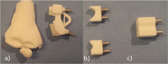
Photographs of the different parts of the patient-specific instrument used for cubitus varus correction.
Fig. 4.
Photographs of the successive surgical steps showing how a) the patient-specific instrument (PSI) is placed at the surface of the bone and four 2 mm Kirschner wires (K-wires) are inserted; b) the first PSI is removed and replaced by two other PSIs that present a flat surface to guide the saw blade; c) the saw blade is guided by the PSI; d) the closing wedge is removed; e) a final PSI brings the four K-wires into alignment (as an external fixator). The targeted correction is automatically obtained (according to the pre-operative planning).
Surgical technique
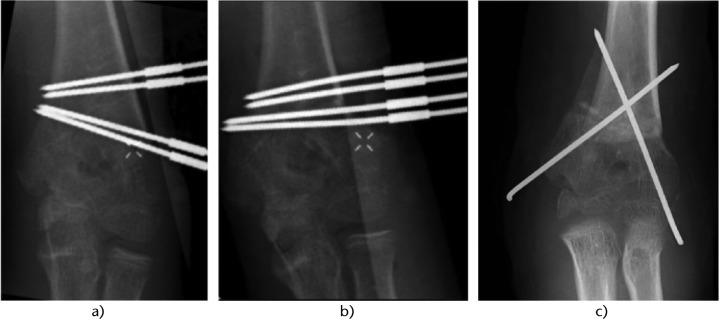
During the surgery, the patient is positioned in the supine position with the arm placed on an arm board with a tourniquet. A 4 cm to 5 cm lateral approach is used. After soft-tissue dissection, the periosteum is incised longitudinally and the distal humeral metaphysis is exposed subperiosteally. The PSI is displaced until the unique position is reached. Four 2 mm K-wires are inserted in the distal humerus by following the PSI (Figs 4a and 5a). The PSI is cut into two parts, and these sections are removed. Two other PSIs are inserted (Fig. 4b) following the K-wires to perform the closing wedge with oscillating saw (Fig. 4c). The wedge fragment is removed (Fig. 4d). The planned correction is directly obtained by aligning the four K-wires in a third guide used as a temporary external fixator (Figs 4e and 5b). A medial translation of the distal fragment along the wires is still possible to decrease the prominence. Final osteosynthesis is obtained by two crossed 2 mm K-wires (Fig. 5b). The four initial K-wires are finally removed. In the post-operative period, the child is immobilised in a long-arm posterior splint with the elbow flexed at 90° for three weeks without change.
Fig. 5.
Radiograph of the surgical steps showing a) the four Kirschner wires (K-wires) inserted following the first patient-specific instrument (PSI); b) the four K-wires are aligned in the last PSI giving the desired correction; and c) two crossed K-wires fix the correction and the four K-wires are removed.
Application for tarsal coalition resection
Tarsal coalition or congenital tarsal synostosis is characterised by an abnormal bony, cartilaginous or fibrous junction between two or more hind- and/or mid-foot bones. It occurs with an incidence of about 1% of the general population and is bilateral in 50% of cases.8,20 Talocalcaneal and calcaneonavicular coalitions are the most frequent forms. It is a frequent cause of foot and ankle pain, with onset during the second decade of life or later. Subtalar motion (inversion and eversion) may be impaired and iterative ankle sprain, flat-foot and tarsal tunnel syndrome may occur. Diagnosis is given by radiograph for calcaneonavicular coalition (AP, oblique and lateral views) and by CT for talocalcaneal coalition. Surgery is indicated only in cases of symptomatic tarsal coalition resistant to conservative management. One favoured technique is triple arthrodesis (talocalcaneal, talonavicular and calcaneocuboid), but long-term follow-up has shown onset of secondary tibiotarsal osteoarthritis in 58% to 77% of cases.21,22 An alternative method consists of resecting the synostosis, providing good results in terms of pain alleviation and prevention of osteoarthritis,23,24 although not in all reports. It is not always straightforward during actual surgery to determine precise location and orientation of the saw blade for bone bridge resection, and it is also difficult to stop sawing before breaching the healthy talocalcaneal joint. Fluoroscopy is often not useful for talocalcaneal coalition. Arthroscopic resection has also been reported,24,25 but involves a long learning curve,26 longer operating time,27, risk of posterior tibial pedicle neurovascular lesion28 and difficulty in positioning.29
Pre-operative 3D-planning and PSI
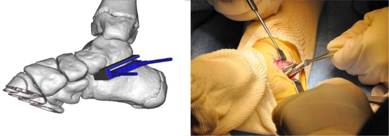
A pre-operative CT scan of the coalition is performed with a minimal resolution of 1 mm spacing between slices and 2 mm slice thickness. Using 3D planning software, the PSI is virtually designed, then manufactured, comprising one reusable standardised titanium component and a second patient-specific polyamide component (Fig. 6).
Fig. 6.
Images showing patient-specific instrument compound of two components: the titanium component is standardised and reusable, while the polyamide component is made by rapid prototyping. There is metal-metal contact between the guide and the Kirschner wires and saw blade, avoiding soft-tissue contamination by potential polyamide debris.
Surgical technique
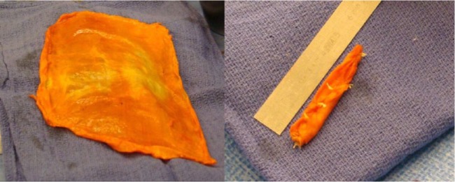
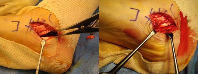
The patient is positioned in dorsal decubitus, with a pneumatic tourniquet on the thigh. In talocalcaneal coalition, the approach is medial, with an incision over the sustentaculum tali. The posterior tibial and flexor hallucis longus tendons are retracted respectively forward and backward to expose the bone bridge. In calcaneonavicular coalition, the incision is anterolateral, forwards of the sinus tarsi; the extensor digitorum brevis muscle is reclined distally, exposing the coalition. The PSI is positioned on the bone surface, having been designed so as to give a perfect fit in a single possible position. It is fixed using two K-wires to ensure stability, and can then guide the direction of the saw blade. It is further designed to ensure correct resection depth, the blade being introduced fully into the PSI so as to reach but not damage the healthy subtalar joint. To reduce recurrence risk, a frozen fascia lata allograft is folded several times before positioning, to obtain a ‘concertina’ effect between the talus and calcaneum (Figs. 7 and 8). At the end of the surgery, the capsular and tendinous planes are carefully closed. Walking is systematically resumed as soon as pain allows. Physical therapy for mid- and hind-foot mobilisation is initiated at one week. Sport is authorised at six months. The technique has the advantages of increasing accuracy and reducing surgery time, and the surgical approach is smaller.8
Fig. 7.
Photographs showing how a fascia lata allograft is folded to obtain a ‘concertina’ effect.
Fig. 8.
Photographs showing how a distractor opens the resection area and the fascia lata allograft is inserted and then sutured with the capsule.
Application for tumour resection and allograft reconstruction
Osteosarcoma and Ewing’s sarcoma are the most frequent malignant primary bone tumours in children, while chondrosarcoma is the most frequent in adults. Improvements in diagnosis and therapeutic techniques increased the possibility of limb-salvage surgery. The function of the reconstructed limb is a major factor, especially in young and physically active patients who place high demands on their limb. The limb reconstruction must also be durable because life expectancy for many of these patients is several decades. However, several studies suggest that limb-salvage surgery increases the local recurrence, in cases of inadequate margin excision.30 To achieve local control of the disease and improve oncological results, wide resection margins are mandatory. This wide surgical excision results in a large residual bone defect that needs restoration. By using PSI the width of the margins may be decreased.7 The resection is carefully planned before surgery, based on MRI and CT scans that are used to define the trajectories of the resection. Limb reconstruction for such large defects can be performed by different techniques, including: endoprosthetic reconstruction, osteoarticular allograft, vascularised autograft, bone transport with distraction osteogenesis or re-implantation of the tumour-bearing bone segment after devitalisation of the tumour cells (by heating, freezing or extracorporeal irradiation). Massive bone allografts present some drawbacks, including relatively long rehabilitation due to immobilisation and partial weight-bearing, difficulties in obtaining size-matched allografts for small patients, the absence of expandability, and the relatively high incidence of complications.31 Despite these drawbacks, allografts offer several advantages, including the ability to re-attach host ligamentous and tendinous structures to the graft. Others advantages are the biological incorporation of the graft (at least partially) and the preservation of the joint, the juxta-articular bone and the growth-plates.32 These advantages make massive bone allografts convenient for intercalary, osteoarticular or arthrodesis operations, and for allograft-prosthetic composite reconstruction in an extra-articular resection. Bone allograft is the most common option for intercalary reconstruction, with survival rates as high as 75% to 89% at ten years.31,33,34
Example of Ewing sarcoma resection of the pelvis (zones I, II and IV of Enneking)
Pre-operative planning for tumour resection
Pre-operative bone CT and MRI scans are obtained respectively for CT with 0.5 mm spacing between slices and 1 mm slice thickness, and for MRI according to the resolution needed for diagnosis. The open-source software ITK-Snap 2.0.0 35 is used to manually delineate the tumour on each MRI slice where it is visible.
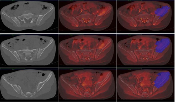
Multi-modal registration allows merging of the MRI and the delineated tumour volume with the CT, making both studies share the same co-ordinate system (Figs 9 and 10). The cutting planes are initially brought into contact with the tumour and then translated back with a surgeon-defined security margin of at least 5 mm. PSIs are virtually designed and made by additive manufacturing using a biocompatible material (Figs 11 and 12).
Fig. 9.
MRIs of an 11-year-old girl with Ewing’s sarcoma of the left iliac wing involving zones I, II and IV of Enneking. Left, CT of the pelvis; middle, merging of CT and MRI; right, tumour delineated on the MRI merged with CT.
Fig. 10.
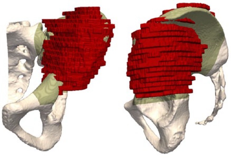
Images of the CT of the patient’s pelvis with the tumour delineated (red).
Fig. 11.
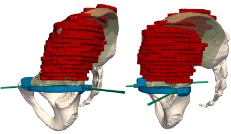
Images showing how a first patient-specific instrument is created to guide the horizontal cut in the upper part of the acetabulum and the vertical cut in the pubis.
Fig. 12.
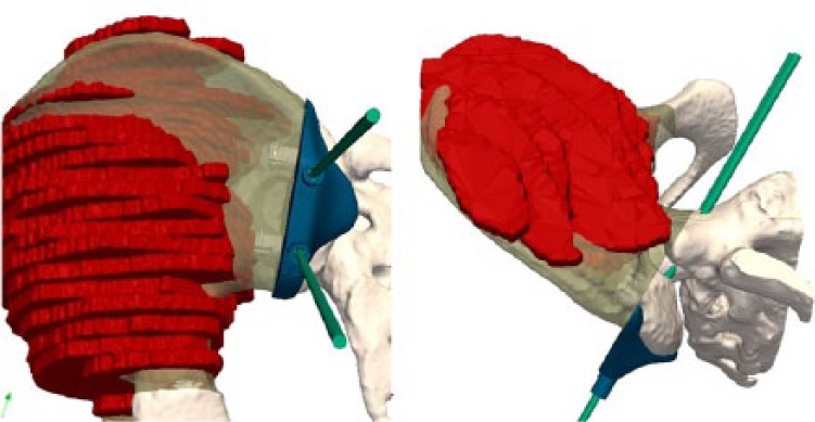
Images showing how a second PSI is created to guide the vertical cut in the posterior iliac crest and the sacral ala.
Pre-operative planning for allograft preparation
To select the best-fitting allograft amongst those available from the local bone bank, CT scans of all available corresponding allografts are acquired (0.35 mm slice thickness, 0.7 mm spacing between slices). A CT-based registration is performed between the patient’s bone and the available allografts. Once the optimal allograft is chosen, the CT-to-CT registration permits the transfer of the cutting planes of the tumour resection to the co-ordinate system of the allograft’s CT (Fig. 13). This procedure ensures that the target planes for the patient and allograft are identical. In this case, the patient was 11 years old. The allograft, being harvested from an adult donor, was over-sized. It had been planned to cut the superior iliac crest to adjust its size and to be able to close the surgical approach (Fig. 13). A second instrument specific to the graft was designed and manufactured to assist the allograft cutting (Fig. 13). The obtained virtual reconstruction was a good fit with the normal anatomy (Fig. 14). The operating time was seven hours. No femoral or sciatic nerve palsy was encountered. The patient observed a six-week non-weight-bearing period before walking with crutches for six additional weeks.
Fig. 13.
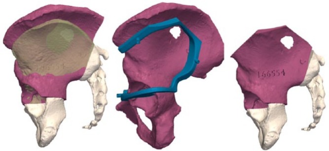
Left: simulated reconstruction: allograft (red) inserted in the gap obtained after tumour resection. The allograft was harvested from a female adult but is oversized by comparison with the iliac wing of the 11-year-old girl. Matching and positioning of the allograft aim to obtain congruency in the acetabulum. Middle: a specific instrument is created to obtain the appropriate cutting. Right: the allograft has been cut to decrease its size.
Fig. 14.
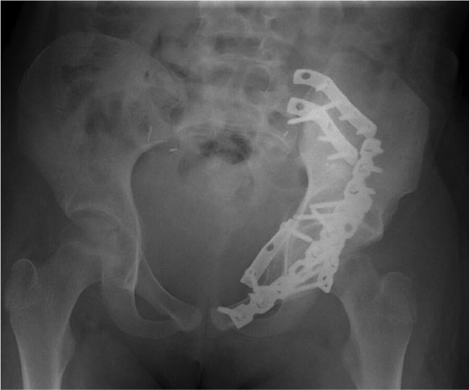
Radiograph of the reconstruction.
Cost implications of PSIs in paediatric orthopaedics
The cost of the planning and manufacturing of a single PSI, for example for a complex 3D-osteotomy, is about €800, and for two PSIs for both tumour resection and allograft cutting, the cost is in the region of €1600.
Summary
Three examples of computer-assisted surgery using PSIs (patient-specific instruments) in paediatric orthopaedics have been presented. With PSIs, we have found an increase in accuracy and a reduction in operating time. Another advantage is that fluoroscopy is no longer needed during the surgery. These advantages represent a benefit for the patient and for the surgeon at an acceptable cost.
Footnotes
Conflict of Interest: Paul Laurent and Khanh TranDuy are founders of 3D Side, a patient-specific surgical technology manufacturer.
Funding
This research received a grant from Fondation Contre le Cancer (GrantSCIE2010-184) (www.cancer.be).
References
- 1. Thompson CJ, Bertrand G. A computer program to aid the neurosurgeon to locate probes used during stereotaxic surgery on deep cerebral structures. Comput Programs Biomed 1972;2:265-76. [DOI] [PubMed] [Google Scholar]
- 2. Lavallée S, Sautot P, Troccaz J, Cinquin P, Merloz P. Computer-assisted spine surgery: a technique for accurate transpedicular screw fixation using CT data and a 3-D optical localizer. J Image Guid Surg 1995;1:65-73. [DOI] [PubMed] [Google Scholar]
- 3. Hüfner T, Kfuri M, Jr, Galanski M, et al. New indications for computer-assisted surgery: tumor resection in the pelvis. Clin Orthop Relat Res 2004;426:219-25. [DOI] [PubMed] [Google Scholar]
- 4. Docquier PL, Paul L, Cartiaux O, Delloye C, Banse X. Computer-assisted resection and reconstruction of pelvic tumor sarcoma. Sarcoma 2010;2010:125162. [DOI] [PMC free article] [PubMed] [Google Scholar]
- 5. Tricot M, Duy KT, Docquier PL. 3D-corrective osteotomy using surgical guides for posttraumatic distal humeral deformity. Acta Orthop Belg 2012;78:538-42. [PubMed] [Google Scholar]
- 6. Cartiaux O, Paul L, Francq BG, Banse X, Docquier PL. Improved accuracy with 3D planning and patient-specific instruments during simulated pelvic bone tumor surgery. Ann Biomed Eng 2014;42:205-13. [DOI] [PubMed] [Google Scholar]
- 7. Bellanova L, Paul L, Docquier PL. Surgical guides (patient-specific instruments) for pediatric tibial bone sarcoma resection and allograft reconstruction. Sarcoma 2013;2013:787653. [DOI] [PMC free article] [PubMed] [Google Scholar]
- 8. de Wouters S, Tran Duy K, Docquier PL. Patient-specific instruments for surgical resection of painful tarsal coalition in adolescents. Orthop Traumatol Surg Res 2014;100:423-7. [DOI] [PubMed] [Google Scholar]
- 9. Sugano N. Computer-assisted orthopedic surgery. J Orthop Sci 2003;8:442-8. [DOI] [PubMed] [Google Scholar]
- 10. Radermacher K, Portheine F, Anton M, et al. Computer assisted orthopaedic surgery with image based individual templates. Clin Orthop Relat Res 1998;354:28-38. [DOI] [PubMed] [Google Scholar]
- 11. Salako F, Aubin C-E, Fortin C, Labelle H. Feasibility study of patient-specific surgical templates for the fixation of pedicle screws. Stud Health Technol Inform 2002;88:419-22. [PubMed] [Google Scholar]
- 12. Leiggener C, Messo E, Thor A, Zeilhofer H-F, Hirsch J-M. A selective laser sintering guide for transferring a virtual plan to real time surgery in composite mandibular reconstruction with free fibula osseous flaps. Int J Oral Maxillofac Surg 2009;38:187-92. [DOI] [PubMed] [Google Scholar]
- 13. Modabber A, Legros C, Rana M, et al. Evaluation of computer-assisted jaw reconstruction with free vascularized fibular flap compared to conventional surgery: a clinical pilot study. Int J Med Robot 2012;8:215-20. [DOI] [PubMed] [Google Scholar]
- 14. Radermacher K, Portheine F, Zimolong A, et al. Image guided orthopedic surgery using individual templates. In: Troccaz J, Grimson E, Mösges R, eds. Lecture notes in computer science. CVRMed-MRCAS’97. Berlin, Heidelberg: Springer, 1997:606-15. [Google Scholar]
- 15. Schkommodau E, Decker N, Klapper U, et al. Pedicle screw implantation using the DISOS template system. In: Stiehl JB, Konermann WH, Haaker RG, eds. Navigation and robotics in total joint and spine surgery. Berlin: Springer, 2004:501-5. [Google Scholar]
- 16. Staudte H-W, Schkommodau E, Honscha M, Portheine F, Radermacher K. Pelvic osteotomy with template navigation. In: Stiehl JB, Konermann WH, Haaker RG, eds. Navigation and robotics in total joint and spine surgery. Berlin, Heidelberg: Springer, 2004:455-63. [Google Scholar]
- 17. Birnbaum K, Schkommodau E, Decker N, et al. Computer-assisted orthopedic surgery with individual templates and comparison to conventional operation method. Spine (Phila Pa 1976) 2001;26:365-70. [DOI] [PubMed] [Google Scholar]
- 18. Bellemore MC, Barrett IR, Middleton RW, Scougall JS, Whiteway DW. Supracondylar osteotomy of the humerus for correction of cubitus varus. J Bone Joint Surg [Br] 1984;66-B:566-72. [DOI] [PubMed] [Google Scholar]
- 19. Takeyasu Y, Oka K, Miyake J, et al. Preoperative, computer simulation-based, three-dimensional corrective osteotomy for cubitus varus deformity with use of a custom-designed surgical device. J Bone Joint Surg [Am] 2013;95-A:e173. [DOI] [PubMed] [Google Scholar]
- 20. Varner KE, Michelson JD. Tarsal coalition in adults. Foot Ankle Int. 2000;21:669-72. [DOI] [PubMed] [Google Scholar]
- 21. Pell RF, IV, Myerson MS, Schon LC. Clinical outcome after primary triple arthrodesis. J Bone Joint Surg [Am] 2000;82-A:47-57. [DOI] [PubMed] [Google Scholar]
- 22. Wetmore RS, Drennan JC. Long-term results of triple arthrodesis in Charcot-Marie-Tooth disease. J Bone Joint Surg [Am] 1989;71-A:417-22. [PubMed] [Google Scholar]
- 23. Cohen BE, Davis WH, Anderson RB. Success of calcaneonavicular coalition resection in the adult population. Foot Ankle Int 1996;17:569-72. [DOI] [PubMed] [Google Scholar]
- 24. Comfort TK, Johnson LO. Resection for symptomatic talocalcaneal coalition. J Pediatr Orthop 1998;18:283-8. [PubMed] [Google Scholar]
- 25. Bonasia DE, Phisitkul P, Saltzman CL, Barg A, Amendola A. Arthroscopic resection of talocalcaneal coalitions. Arthroscopy 2011;27:430-5. [DOI] [PubMed] [Google Scholar]
- 26. Knörr J, Accadbled F, Abid A, et al. Arthroscopic treatment of calcaneonavicular coalition in children. Orthop Traumatol Surg Res 2011;97:565-8. [DOI] [PubMed] [Google Scholar]
- 27. Lui TH, Chan LK, Chan KB. Medial subtalar arthroscopy: a cadaveric study of the tarsal canal portal. Knee Surg Sports Traumatol Arthrosc 2013;21:1279-82. [DOI] [PubMed] [Google Scholar]
- 28. Wilde PH, Torode IP, Dickens DR, Cole WG. Resection for symptomatic talocalcaneal coalition. J Bone Joint Surg [Br] 1994;76-B:797-801. [PubMed] [Google Scholar]
- 29. Jagodzinski NA, Hughes A, Davis NP, et al. Arthroscopic resection of talocalcaneal coalitions–a bicentre case series of a new technique. Foot Ankle Surg 2013;19:125-30. [DOI] [PubMed] [Google Scholar]
- 30. Grimer RJ. Surgical options for children with osteosarcoma. Lancet Oncol 2005;6:85-92. [DOI] [PubMed] [Google Scholar]
- 31. Brigman BE, Hornicek FJ, Gebhardt MC, Mankin HJ. Allografts about the knee in young patients with high-grade sarcoma. Clin Orthop Relat Res 2004;421:232-9. [DOI] [PubMed] [Google Scholar]
- 32. Gebhardt MC, Flugstad DI, Springfield DS, Mankin HJ. The use of bone allografts for limb salvage in high-grade extremity osteosarcoma. Clin Orthop Relat Res 1991;270:181-96. [PubMed] [Google Scholar]
- 33. Donati D, Di Liddo M, Zavatta M, et al. Massive bone allograft reconstruction in high-grade osteosarcoma. Clin Orthop Relat Res 2000;377:186-94. [DOI] [PubMed] [Google Scholar]
- 34. Alman BA, De Bari A, Krajbich JI. Massive allografts in the treatment of osteosarcoma and Ewing sarcoma in children and adolescents. J Bone Joint Surg [Am] 1995;77-A:54-64. [DOI] [PubMed] [Google Scholar]
- 35. Yushkevich PA, Piven J, Hazlett HC, et al. User-guided 3D active contour segmentation of anatomical structures: significantly improved efficiency and reliability. Neuroimage 2006;31:1116-28. [DOI] [PubMed] [Google Scholar]


