

There are elements in this study that suggest the presence of alveolar collapse in an early stage when there is only little fibrosis, supporting the theory that alveolar collapse might be the initial trigger for the fibroproliferative process in patients with idiopathic pulmonary fibrosis.
Abstract
Purpose
To elucidate the underlying lung changes responsible for the computed tomographic (CT) features of idiopathic pulmonary fibrosis (IPF) and to gain insight into the way IPF proceeds through the lungs and progresses over time.
Materials and Methods
Micro-CT studies of tissue cores obtained from explant lungs were examined and were correlated 1:1 with a CT study obtained immediately before transplantation. Samples for histologic analysis were obtained from selected cores.
Results
In areas with no or minimal abnormalities on CT images, small areas of increased attenuation located in or near the interlobular septa can be seen on micro-CT studies. In more involved lung areas, the number of opacities increases and opacities enlarge and approach each other along the interlobular septa, causing a fine reticular pattern on CT images. Simultaneously, air-containing structures in and around these opacities arise, corresponding with small cysts on CT images. Honeycombing is caused by a progressive increase in the number and size of these cystic structures and tissue opacities that gradually extend toward the centrilobular region and finally replace the entire lobule. At histologic analysis, the small islands of increased attenuation very likely correspond with fibroblastic foci. Near these fibroblastic foci, an abnormal adjacency of alveolar walls was seen, suggesting alveolar collapse. In later stages, normal lung tissue is replaced by a large amount of young collagen, as seen in patients with advanced fibrosis.
Conclusion
Fibrosis and cyst formation in patients with IPF seem to start at the periphery of the pulmonary lobule and progressively extend toward the core of this anatomic lung unit. Evidence was found that alveolar collapse might already be present in an early stage when there is only little pulmonary fibrosis.
© RSNA, 2016
Introduction
In 2002, the American Thoracic Society and the European Respiratory Society set up an international multidisciplinary consensus classification of the different idiopathic interstitial pneumonias (1). This classification, which was updated in 2013 (2), is based on an integrated clinical, radiologic, and pathologic approach, and it defines idiopathic pulmonary fibrosis (IPF) as a specific form of chronic fibrosing interstitial pneumonia of unknown origin that is limited to the lung and is associated with the histologic appearance of usual interstitial pneumonia (UIP). Imaging plays a crucial role in the diagnosis of IPF, with computed tomography (CT) considered to aid in the decision-making process in multidisciplinary conferences (3,4). Indeed, CT yields important information by enabling characterization of the entire lung at a submacroscopic level. CT has a high degree of accuracy in making a correct diagnosis when typical CT features are present, enabling the patient to avoid an invasive biopsy (5–7). This accuracy can be up to 95%, but it decreases substantially when typical signs are absent (8). Even then, CT may indicate the diagnosis in an appropriate clinical setting, or it may help to define when a biopsy would be more informative (1,2).
Typical CT criteria for UIP are well established and include both reticular opacities associated with traction bronchiectasis and honeycombing with a characteristic basal and peripheral distribution (1,2). Although these signs were considered crucial for the diagnosis, it is increasingly recognized that the CT presentation can be very heterogeneous and that a reticular pattern without honeycombing may be seen in patients with UIP and may be sufficient for diagnosis in the proper clinical settings (9,10). These CT changes in patients with early UIP, as well as those in patients with more advanced UIP, often manifest with a repeating almost geometric distribution pattern, suggesting pathologic changes that expand by following the contours of a matching anatomic structure. Micro-CT was used to study these CT changes to determine the relationship between these abnormalities and the components of the secondary pulmonary lobule, which is generally considered the basic CT anatomic unit of the lung parenchyma. The purpose of this study was to better understand the underlying lung changes responsible for the CT features of IPF and to gain insight into the way IPF proceeds through the lungs and progresses over time.
Materials and Methods
Subjects
Explant lungs from 10 consecutive white male patients with a diagnosis of end-stage IPF before transplantation were selected. IPF diagnosis was made at a clinico-radiologic-pathologic conference and was based on the combination of clinical, radiologic, and—when a biopsy was available—pathologic features. Postoperative pathologic examination of the explant lungs enabled us to confirm the diagnosis of IPF in nine patients; however, examination findings were more suggestive of chronic hypersensitivity pneumonitis in one patient. Thus, the nine patients with confirmed IPF were used in this study. The mean age of patients was 57.22 years (age range, 51–64 years). Informed consent and permission to use these lung specimens were obtained directly from these patients. This study was approved by the hospital ethics and university biosafety committees in Leuven, Belgium.
Specimen Processing and Sampling
One explanted lung from each patient was donated for scientific research, and lungs were numbered from one to nine. The explanted lungs were prepared by using the method described by McDonough et al (11) and Verleden et al (12). Briefly, after the main-stem bronchus is connected to a compressed air source with an underwater seal, the lung is first inflated to a transpulmonary pressure of 30 cm H2O and then deflated to a transpulmonary pressure of 10 cm H2O. In this state, the lung is frozen in liquid nitrogen vapor and stored at a temperature of −80°C.
The frozen lung specimens were cut into transverse 2-cm-thick slices from lung apex to base with a band saw. Cores approximately 1.4 or 2.6 cm in diameter were then randomly taken from each slice. These tissue samples were fixed in a 1% solution of glutaraldehyde in pure acetone (freezing point, −93°C), precooled to −20°C, and kept at that temperature during the fixation process. After fixation, the samples were warmed to room temperature, washed with a graded series of ethanol concentrations (30%, 70%, 80%, 90%, and 100% ethanol) and then hexamethyldisilazane, and air dried overnight (13).
CT Scans
The most recent CT findings before transplantation were used for correlation with micro-CT findings. The mean time between this CT examination and transplantation was 145.11 days ± 149.82 (standard deviation). At this CT examination, severity and extent of bronchiectasis, ground-glass opacity, consolidation, reticular pattern, honeycomb cysts or honeycombing, pleural thickening, volume loss, and air trapping were estimated semiquantitatively by two experienced chest radiologists (J.A.V., C.M.; 30 and 5 years of experience, respectively) using the method described by De Jong et al (14). These abnormalities were defined according to the Fleischner Society nomenclature (15). Briefly, each abnormality was scored in six lung lobes (lingula included). For each lobe, the extent of the lobe involved with the abnormality was estimated as less than one-third of the lobar volume (score = 1), between one-third and two-thirds of the lobar volume (score = 2), or more than two-thirds of the lobar volume (score = 3). All scores were added and were expressed on a scale of 0–100 because this scale might enable easier interpretation and comparison. Thus, the CT score can be interpreted as a percentage of the lung involved. CT images of the explanted frozen lung specimens were obtained by using a CT scanner (Definition Flash; Siemens) at 120 kV with tube current modulation, collimation of 128 × 0.6 mm, pitch of 1.2, and 1- and 5-mm section thicknesses. These scans were used to facilitate the correlation between preoperative CT and micro-CT studies.
The tissue cores were scanned with a micro-CT scanner (SkyScan 1172; Skyscan, Kontich, Belgium) (resolution, 8.4 µm; 40 kV; 250 mA; no filter). Nrecon software (Skyscan) was used to reconstruct the raw data.
Between 2 and 20 cores per lung were obtained, and a total of 94 cores were analyzed. These cores were selected (a) from areas that appeared normal on the pretransplantation CT scan, (b) from areas with minimal abnormalities (small nodular or irregular opacities, linear opacities, and early reticulation), (c) from areas with a clear reticular pattern and small cystic changes, and (d) from areas that showed progressive distortion and honeycombing. In this way, 20–24 cores within each of these four groups were examined.
Correlation of Preoperative CT Studies, CT Studies of the Explanted Frozen Lung, and Micro-CT Studies
The micro-CT images of the tissue cores were registered (C.M., J.A.V.) with the preoperative in vivo CT images and the explanted frozen lung CT images by using software developed within the ICON-IBBT AIR project (16) to exactly match the lung areas studied with micro-CT with the corresponding areas on the pretransplant CT study. Care was taken to match not only the location but also the orientation and inclination of both studies.
Special attention was given to the location of the abnormal changes in relation to the anatomy of the secondary pulmonary lobule.
Histologic Analysis
In each of the four previously mentioned areas, cores were also selected for histologic analysis, whereby slices were obtained and correlated with corresponding micro-CT and CT studies. Histologic analysis was performed on the cores after they were prepared as previously described in the Specimen Processing and Sampling section. To find the corresponding slice within the core, each core was first divided into five pieces (E.K.V., 30 years of experience). Classic hematoxylin-eosin staining was performed on a representative slice of each piece. The piece that contained the interesting slice was further divided, and hematoxylin-eosin staining was performed after every few cuts to find the slice of interest. Finally, hematoxylin-eosin staining was also performed on the selected slices. It should be noted that these histologic slices are different from those obtained with lung biopsy. Because cellular structures were sometimes disturbed during processing, tissue characterization could be difficult. That is why additional picrosirius red staining was performed and samples were viewed under a microscope with an attached polarization filter. Polarized light microscopy was chosen because it has been shown to be useful in assessment of the maturity of collagen through the way fibers are organized. Picrosirius red staining enhances the polarizing features of collagen (17).
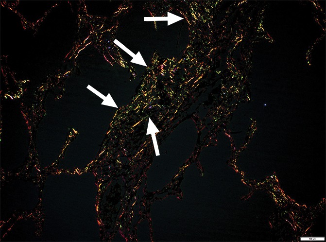
The theory is that in tissue scarring, as in fibrosis, young collagen fibers are deposited as fine disorganized fibers that show no or minimal birefringence (green), while native collagen is organized in thick bundles and shows strong birefringence; thus, native collagen appears as bright yellow to red structures on a dark background in the polarizing microscope (17–19).
Statistical Analysis
Statistical analysis was not performed because the study was purely descriptive.
Results
All lungs showed the typical CT features of UIP: (a) an irregular linear to reticular pattern that was most pronounced in the basal and peripheral lung areas with peripheral cystic changes (honeycombing) and (b) traction bronchiectasis in the basal parts of the lung (4,20,21). The scoring is presented in the Table.
Scoring of CT Signs on Pretransplantation CT Images
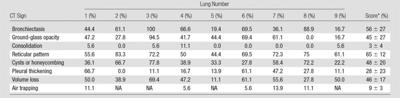
Note.—NA = no expiration scan was acquired.
*Data are mean ± standard deviation.
Invisible Abnormalities on CT Studies
Cores taken from regions that appeared normal on CT studies (Fig 1) and that were located in the apical and central areas showed no changes on micro-CT studies. Figure 1b shows a micro-CT image of a core obtained in an apical lung region that appeared unaffected at CT (Fig 1a). There is a good correlation between CT images and micro-CT images, with corresponding anatomic structures (ie, blood vessels and airways) recognizable on both images. Figure 1 also shows that the interlobular septa are clearly depicted on micro-CT studies.
Figure 1a:
There are no visible abnormalities on either image. (a) CT image at the apical part of lung 1. White outline indicates the region where the core was obtained. Scale bar = 1 cm. (b) Micro-CT image of the core shows normal blood vessels (black arrows) and interlobular septa (white arrows). Scale bar = 1 mm.
Figure 1b:
There are no visible abnormalities on either image. (a) CT image at the apical part of lung 1. White outline indicates the region where the core was obtained. Scale bar = 1 cm. (b) Micro-CT image of the core shows normal blood vessels (black arrows) and interlobular septa (white arrows). Scale bar = 1 mm.
Areas of Ground-Glass Opacification on CT Images
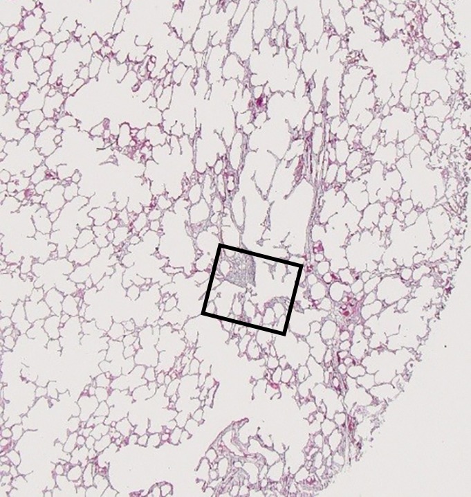
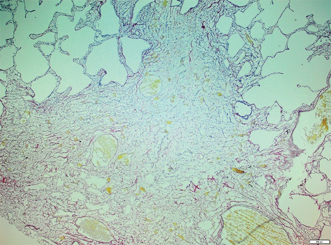
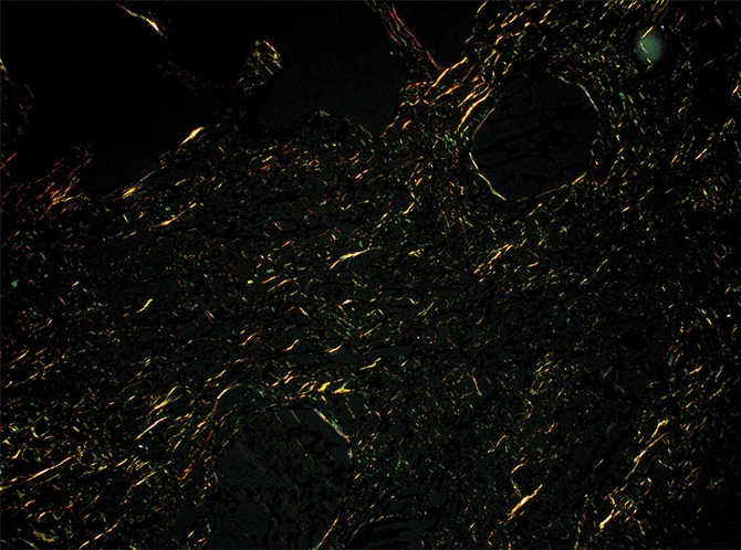
The amount of ground-glass opacification seen on the preoperative CT images in our study group is higher than would be expected in patients with UIP; this is illustrated by the high score for ground-glass opacity (Table). This is probably related to the fact that our scoring method includes all areas of ground-glass opacity and does not discriminate between the ground-glass opacities that have been described in the very early stage of UIP, the increased attenuation in the dependent lung due to hypoventilation, or the increased attenuation that is observed in the clearly abnormal and fibrotic regions. In our study, ground-glass opacity on CT images was mostly related to the latter condition and corresponded to areas of overt fibrosis on micro-CT images. However, Figure 2a, shows a CT section of lung 3, in which ground-glass opacity can be seen in the dependent lung without overt fibrotic changes. The corresponding micro-CT study was almost normal, except for the presence of some small islands of increased attenuation which, if followed through the core, were clearly adjacent to an interlobular septum. Histologic analysis was performed at this level (Fig 2c–2e), and the small island of increased attenuation on micro-CT images corresponded predominantly with abnormal and irregular strands of young polarizing collagen. In addition, polarization of native collagen was seen at the periphery of the lesion and in the surrounding normal alveolar walls.
Figure 2a:
Images show areas of ground-glass opacity. (a) CT image of lung 3 shows ground-glass opacities in the dependent area in the right upper lobe. Scale bar = 1 cm. (b) Micro-CT image at the same level as a shows some small areas of increased attenuation (arrows). Scale bar = 1 mm. (c) Photomicrograph corresponds to b. (Hematoxylin-eosin stain; original magnification, ×12.) (d) Photomicrograph corresponds to the indicated region in c. (Picrosirius red stain; original magnification, ×100.) (e) Photomicrograph of the same region as in d obtained with a polarizing filter. The opacities on b correspond to areas of abnormal tissue, with a reticular network of fine green fibers (white arrows) and a few thicker strands of red collagen at the periphery (black arrows).
Figure 2c:
Images show areas of ground-glass opacity. (a) CT image of lung 3 shows ground-glass opacities in the dependent area in the right upper lobe. Scale bar = 1 cm. (b) Micro-CT image at the same level as a shows some small areas of increased attenuation (arrows). Scale bar = 1 mm. (c) Photomicrograph corresponds to b. (Hematoxylin-eosin stain; original magnification, ×12.) (d) Photomicrograph corresponds to the indicated region in c. (Picrosirius red stain; original magnification, ×100.) (e) Photomicrograph of the same region as in d obtained with a polarizing filter. The opacities on b correspond to areas of abnormal tissue, with a reticular network of fine green fibers (white arrows) and a few thicker strands of red collagen at the periphery (black arrows).
Figure 2e:
Images show areas of ground-glass opacity. (a) CT image of lung 3 shows ground-glass opacities in the dependent area in the right upper lobe. Scale bar = 1 cm. (b) Micro-CT image at the same level as a shows some small areas of increased attenuation (arrows). Scale bar = 1 mm. (c) Photomicrograph corresponds to b. (Hematoxylin-eosin stain; original magnification, ×12.) (d) Photomicrograph corresponds to the indicated region in c. (Picrosirius red stain; original magnification, ×100.) (e) Photomicrograph of the same region as in d obtained with a polarizing filter. The opacities on b correspond to areas of abnormal tissue, with a reticular network of fine green fibers (white arrows) and a few thicker strands of red collagen at the periphery (black arrows).
Figure 2b:
Images show areas of ground-glass opacity. (a) CT image of lung 3 shows ground-glass opacities in the dependent area in the right upper lobe. Scale bar = 1 cm. (b) Micro-CT image at the same level as a shows some small areas of increased attenuation (arrows). Scale bar = 1 mm. (c) Photomicrograph corresponds to b. (Hematoxylin-eosin stain; original magnification, ×12.) (d) Photomicrograph corresponds to the indicated region in c. (Picrosirius red stain; original magnification, ×100.) (e) Photomicrograph of the same region as in d obtained with a polarizing filter. The opacities on b correspond to areas of abnormal tissue, with a reticular network of fine green fibers (white arrows) and a few thicker strands of red collagen at the periphery (black arrows).
Figure 2d:
Images show areas of ground-glass opacity. (a) CT image of lung 3 shows ground-glass opacities in the dependent area in the right upper lobe. Scale bar = 1 cm. (b) Micro-CT image at the same level as a shows some small areas of increased attenuation (arrows). Scale bar = 1 mm. (c) Photomicrograph corresponds to b. (Hematoxylin-eosin stain; original magnification, ×12.) (d) Photomicrograph corresponds to the indicated region in c. (Picrosirius red stain; original magnification, ×100.) (e) Photomicrograph of the same region as in d obtained with a polarizing filter. The opacities on b correspond to areas of abnormal tissue, with a reticular network of fine green fibers (white arrows) and a few thicker strands of red collagen at the periphery (black arrows).
Minimal Changes on CT Images
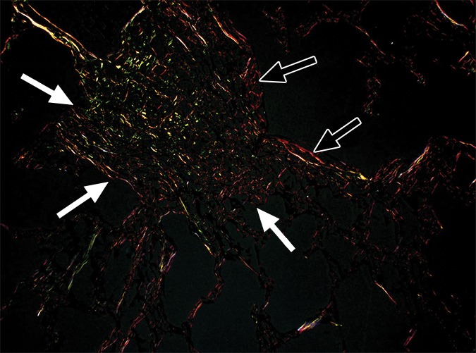
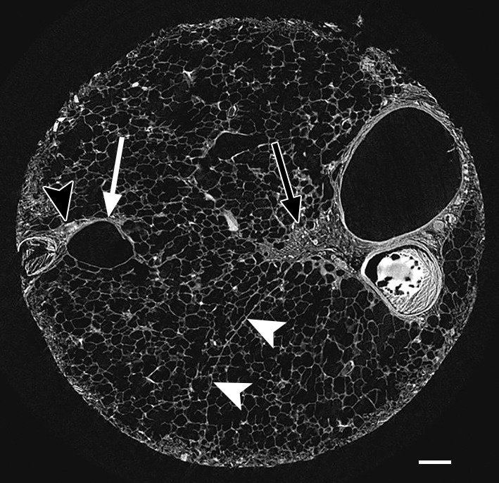
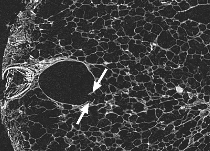
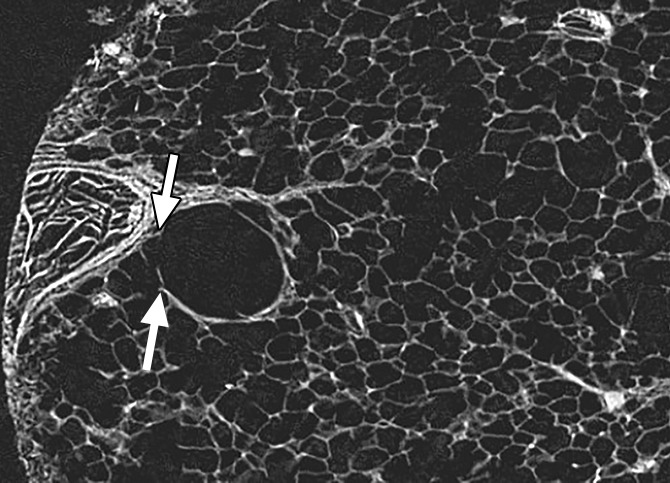
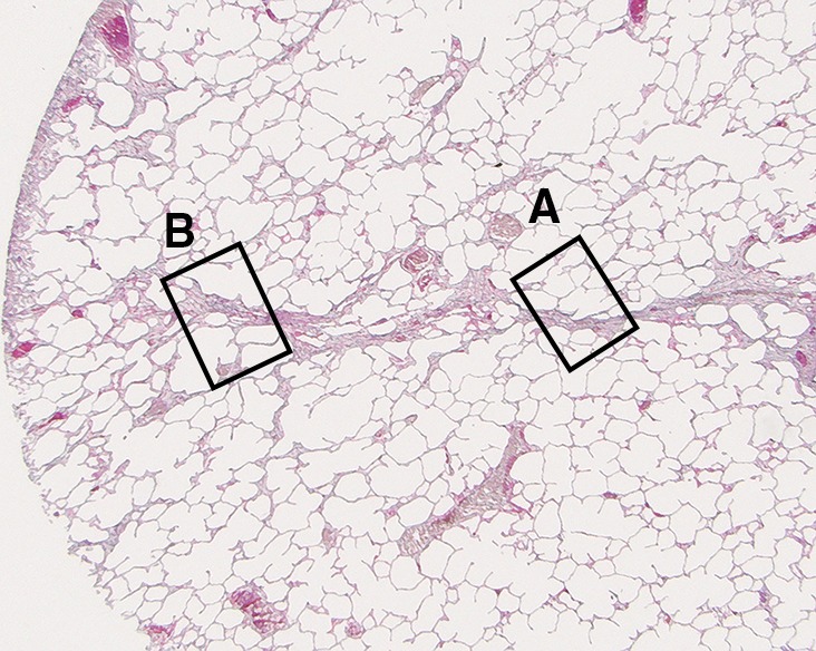
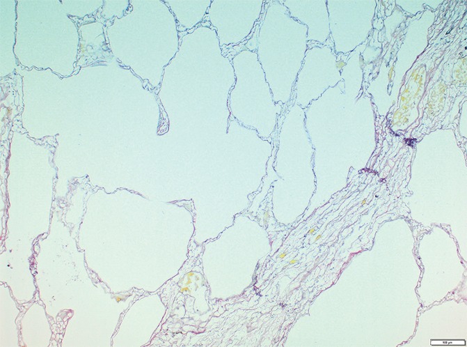
In our study group, minimal changes on CT images often were observed in the relatively spared upper regions of both lungs and consisted of small dots, small irregular linear opacities, and, occasionally, small cystic structures. Figure 3a shows a CT image of the upper part of the left lung where a linear opacity and a cystic structure can be seen. On micro-CT images (Fig 3b), the linear opacity corresponds to an added tissue opacity adjacent to a bronchovascular bundle and a nearby interlobular septum. The hypoattenuated round structure is not a section through an airway but an abnormal cystic structure next to a vein that is also located adjacent to an interlobular septum and is connected to alveolar ducts or sacs (Fig 3c, 3d). Some abnormal tissue opacities can be seen adjacent to this cystic structure. Figure 4a shows a micro-CT slice from another area in the same lung that was also minimally involved at CT. Again, small somewhat longer and more irregular linear islands of increased attenuation adjacent to the interlobular septum can be seen. Hemotoxylin-eosin (Fig 4b) and picrosirius red (Fig 4c–4f) staining were performed for this slice. The slice stained with picrosirius red was viewed without (Fig 4c, 4e) and with (Fig 4d, 4f) a polarization filter. In one part of this linear opacity, bundles of strongly polarizing collagen orderly organized next to each other in a parallel direction can be seen (Fig 4d). This type of collagen is also seen in the alveolar walls. However, in the more irregular parts of this linear opacity, collagen fibers are fine, irregular, and disorganized (Fig 4f).
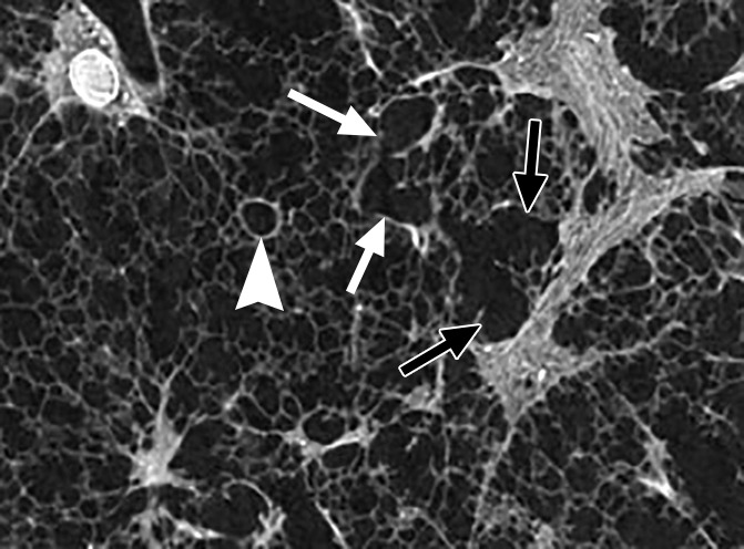
Figure 3a:
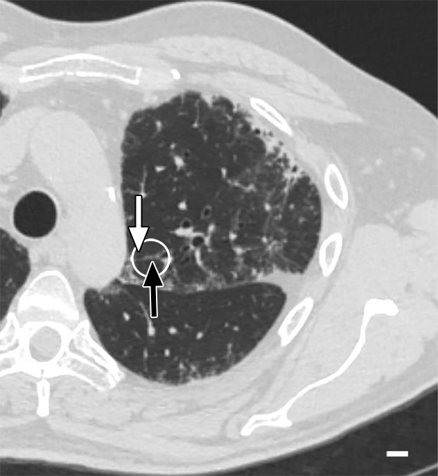
Images show minimal changes. (a) CT image obtained in the apical part of lung 1. There is a linear opacity (black arrow) with a horizontal course, possibly corresponding to an interlobular septum. There is a small cyst (white arrow) in the medial subpleural region. Scale bar = 1 cm. (b) Micro-CT image shows the linear opacity corresponds to an abnormal island of increased attenuation (black arrow) adjacent to a bronchovascular structure and to a nearby interlobular septum (white arrowheads). The hypoattenuated round structure (white arrow) is an abnormal cystic structure next to a vascular structure that is probably a vein in an interlobular septum. Adjacent to this is some increased tissue attenuation (black arrowhead). Scale bar = 1 mm. (c, d) Close-ups of the cystic structure seen in b at two different levels of the micro-CT core. At both levels, connections with alveolar ducts and sacs are seen (arrows).
Figure 3b:
Images show minimal changes. (a) CT image obtained in the apical part of lung 1. There is a linear opacity (black arrow) with a horizontal course, possibly corresponding to an interlobular septum. There is a small cyst (white arrow) in the medial subpleural region. Scale bar = 1 cm. (b) Micro-CT image shows the linear opacity corresponds to an abnormal island of increased attenuation (black arrow) adjacent to a bronchovascular structure and to a nearby interlobular septum (white arrowheads). The hypoattenuated round structure (white arrow) is an abnormal cystic structure next to a vascular structure that is probably a vein in an interlobular septum. Adjacent to this is some increased tissue attenuation (black arrowhead). Scale bar = 1 mm. (c, d) Close-ups of the cystic structure seen in b at two different levels of the micro-CT core. At both levels, connections with alveolar ducts and sacs are seen (arrows).
Figure 3c:
Images show minimal changes. (a) CT image obtained in the apical part of lung 1. There is a linear opacity (black arrow) with a horizontal course, possibly corresponding to an interlobular septum. There is a small cyst (white arrow) in the medial subpleural region. Scale bar = 1 cm. (b) Micro-CT image shows the linear opacity corresponds to an abnormal island of increased attenuation (black arrow) adjacent to a bronchovascular structure and to a nearby interlobular septum (white arrowheads). The hypoattenuated round structure (white arrow) is an abnormal cystic structure next to a vascular structure that is probably a vein in an interlobular septum. Adjacent to this is some increased tissue attenuation (black arrowhead). Scale bar = 1 mm. (c, d) Close-ups of the cystic structure seen in b at two different levels of the micro-CT core. At both levels, connections with alveolar ducts and sacs are seen (arrows).
Figure 3d:
Images show minimal changes. (a) CT image obtained in the apical part of lung 1. There is a linear opacity (black arrow) with a horizontal course, possibly corresponding to an interlobular septum. There is a small cyst (white arrow) in the medial subpleural region. Scale bar = 1 cm. (b) Micro-CT image shows the linear opacity corresponds to an abnormal island of increased attenuation (black arrow) adjacent to a bronchovascular structure and to a nearby interlobular septum (white arrowheads). The hypoattenuated round structure (white arrow) is an abnormal cystic structure next to a vascular structure that is probably a vein in an interlobular septum. Adjacent to this is some increased tissue attenuation (black arrowhead). Scale bar = 1 mm. (c, d) Close-ups of the cystic structure seen in b at two different levels of the micro-CT core. At both levels, connections with alveolar ducts and sacs are seen (arrows).
Figure 4a:
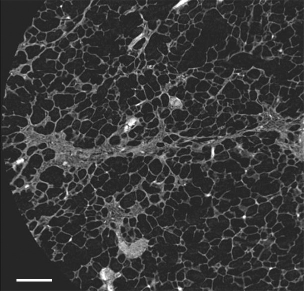
Images show minimal changes. (a) Micro-CT image of a core from lung 1 shows islands of increased tissue attenuation along an interlobular septum. Scale bar = 1 mm. (b) Photomicrograph of the tissue slice corresponding to a. (Hemotoxylin-eosin stain; original magnification, ×12.) (c–f) Photomicrographs obtained without (c, e) and with (d, f) a polarizing filter. (Picrosirius red stain; original magnification, ×100). Native collagen in the alveolar walls shows strong bifrefringence and has a red appearance (white arrows). One part of the linear increased attenuation in sample A (c, d) corresponds with thick bundles of the same red to yellow collagen orderly organized in close contact with each other (black arrows). In sample B (e, f), which was obtained in a more irregular part of the linear opacity, there is an added irregular reticular network of fine green fibers (arrows).
Figure 4b:
Images show minimal changes. (a) Micro-CT image of a core from lung 1 shows islands of increased tissue attenuation along an interlobular septum. Scale bar = 1 mm. (b) Photomicrograph of the tissue slice corresponding to a. (Hemotoxylin-eosin stain; original magnification, ×12.) (c–f) Photomicrographs obtained without (c, e) and with (d, f) a polarizing filter. (Picrosirius red stain; original magnification, ×100). Native collagen in the alveolar walls shows strong bifrefringence and has a red appearance (white arrows). One part of the linear increased attenuation in sample A (c, d) corresponds with thick bundles of the same red to yellow collagen orderly organized in close contact with each other (black arrows). In sample B (e, f), which was obtained in a more irregular part of the linear opacity, there is an added irregular reticular network of fine green fibers (arrows).
Figure 4c:
Images show minimal changes. (a) Micro-CT image of a core from lung 1 shows islands of increased tissue attenuation along an interlobular septum. Scale bar = 1 mm. (b) Photomicrograph of the tissue slice corresponding to a. (Hemotoxylin-eosin stain; original magnification, ×12.) (c–f) Photomicrographs obtained without (c, e) and with (d, f) a polarizing filter. (Picrosirius red stain; original magnification, ×100). Native collagen in the alveolar walls shows strong bifrefringence and has a red appearance (white arrows). One part of the linear increased attenuation in sample A (c, d) corresponds with thick bundles of the same red to yellow collagen orderly organized in close contact with each other (black arrows). In sample B (e, f), which was obtained in a more irregular part of the linear opacity, there is an added irregular reticular network of fine green fibers (arrows).
Figure 4f:
Images show minimal changes. (a) Micro-CT image of a core from lung 1 shows islands of increased tissue attenuation along an interlobular septum. Scale bar = 1 mm. (b) Photomicrograph of the tissue slice corresponding to a. (Hemotoxylin-eosin stain; original magnification, ×12.) (c–f) Photomicrographs obtained without (c, e) and with (d, f) a polarizing filter. (Picrosirius red stain; original magnification, ×100). Native collagen in the alveolar walls shows strong bifrefringence and has a red appearance (white arrows). One part of the linear increased attenuation in sample A (c, d) corresponds with thick bundles of the same red to yellow collagen orderly organized in close contact with each other (black arrows). In sample B (e, f), which was obtained in a more irregular part of the linear opacity, there is an added irregular reticular network of fine green fibers (arrows).
Figure 4e:
Images show minimal changes. (a) Micro-CT image of a core from lung 1 shows islands of increased tissue attenuation along an interlobular septum. Scale bar = 1 mm. (b) Photomicrograph of the tissue slice corresponding to a. (Hemotoxylin-eosin stain; original magnification, ×12.) (c–f) Photomicrographs obtained without (c, e) and with (d, f) a polarizing filter. (Picrosirius red stain; original magnification, ×100). Native collagen in the alveolar walls shows strong bifrefringence and has a red appearance (white arrows). One part of the linear increased attenuation in sample A (c, d) corresponds with thick bundles of the same red to yellow collagen orderly organized in close contact with each other (black arrows). In sample B (e, f), which was obtained in a more irregular part of the linear opacity, there is an added irregular reticular network of fine green fibers (arrows).
Figure 4d:

Images show minimal changes. (a) Micro-CT image of a core from lung 1 shows islands of increased tissue attenuation along an interlobular septum. Scale bar = 1 mm. (b) Photomicrograph of the tissue slice corresponding to a. (Hemotoxylin-eosin stain; original magnification, ×12.) (c–f) Photomicrographs obtained without (c, e) and with (d, f) a polarizing filter. (Picrosirius red stain; original magnification, ×100). Native collagen in the alveolar walls shows strong bifrefringence and has a red appearance (white arrows). One part of the linear increased attenuation in sample A (c, d) corresponds with thick bundles of the same red to yellow collagen orderly organized in close contact with each other (black arrows). In sample B (e, f), which was obtained in a more irregular part of the linear opacity, there is an added irregular reticular network of fine green fibers (arrows).
Reticular Pattern and Small Cystic Changes on CT Images
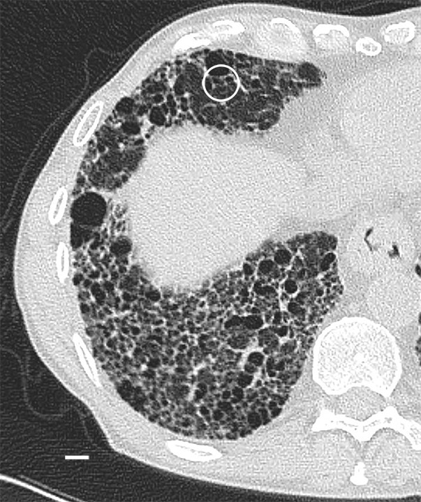
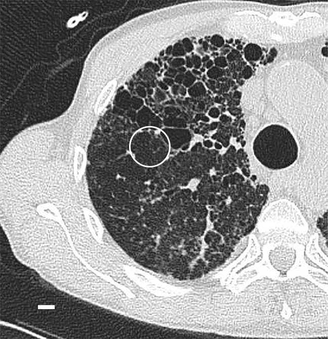
Micro-CT images of a core obtained in a peripheral lung region, where CT depicts linear opacities that by summation start to resemble a net (a reticular pattern), reveal several islands of increased attenuation located close to the interlobular septa (Fig 5). The secondary pulmonary lobule is outlined by these linear opacities that, together with the normal interlobular septa, construct an almost hexagonal figure (Fig 5b) corresponding to the early reticulation seen on CT images. At the center of the lobule, the terminal bronchiole and its accompanying arteriole can be recognized and look normal. However, the alveolar structures surrounding some of these islands of increased attenuation have a distorted appearance. In Figure 5c–5e, a terminal bronchiole is seen dividing into two first-generation respiratory bronchioles, which at their turn divide into second-generation respiratory bronchioles. Instead of giving rise to another generation of respiratory bronchioles or alveolar ducts, these second-generation respiratory bronchioles are terminating abruptly against islands of increased attenuation.
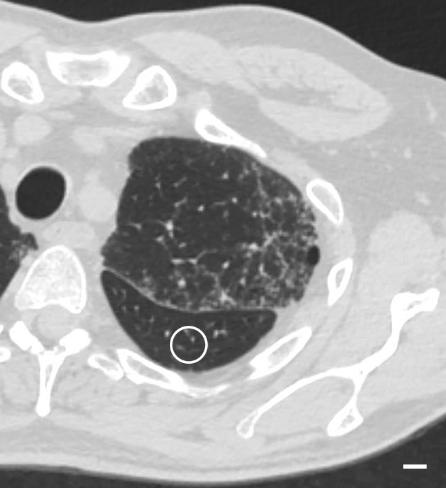
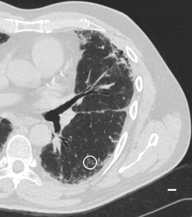
Figure 5a:

Images show the reticular pattern. (a) CT image of the upper part of lung 8. Linear opacities organized as an interrupted reticular pattern can be seen (white ○). Scale bar = 1 cm. (b) Micro-CT image shows contours of the secondary pulmonary lobule (arrowheads) with a terminal bronchiole and accompanying vessel in the center (white arrow). Linear opacities in a correlate with small islands of increased attenuation (black arrows) adjacent to interlobular septa (arrowheads) in b. Scale bar = 1 mm. (c–e) Close-up images of the outlined area in b. A terminal bronchiole (arrowheads) divides into two first-generation respiratory bronchioles (white arrows). The inferior bronchiole divides into two second-generation respiratory bronchioles (black arrows) that abruptly terminate against an irregular island of increased attenuation.
Figure 5b:
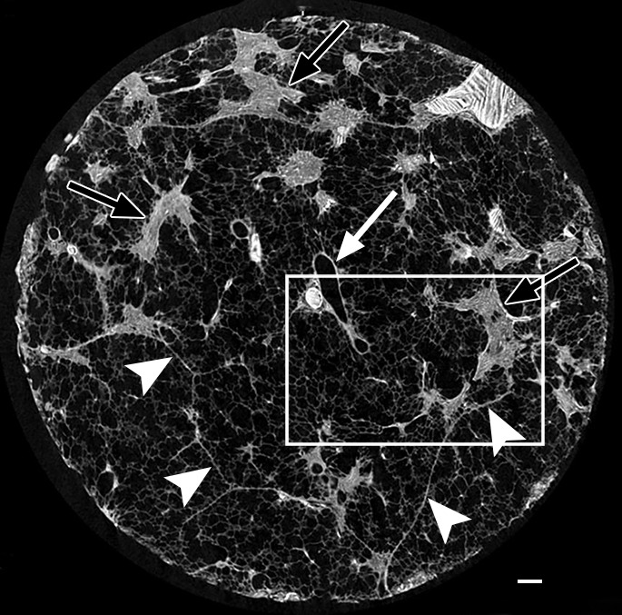
Images show the reticular pattern. (a) CT image of the upper part of lung 8. Linear opacities organized as an interrupted reticular pattern can be seen (white ○). Scale bar = 1 cm. (b) Micro-CT image shows contours of the secondary pulmonary lobule (arrowheads) with a terminal bronchiole and accompanying vessel in the center (white arrow). Linear opacities in a correlate with small islands of increased attenuation (black arrows) adjacent to interlobular septa (arrowheads) in b. Scale bar = 1 mm. (c–e) Close-up images of the outlined area in b. A terminal bronchiole (arrowheads) divides into two first-generation respiratory bronchioles (white arrows). The inferior bronchiole divides into two second-generation respiratory bronchioles (black arrows) that abruptly terminate against an irregular island of increased attenuation.
Figure 5c:
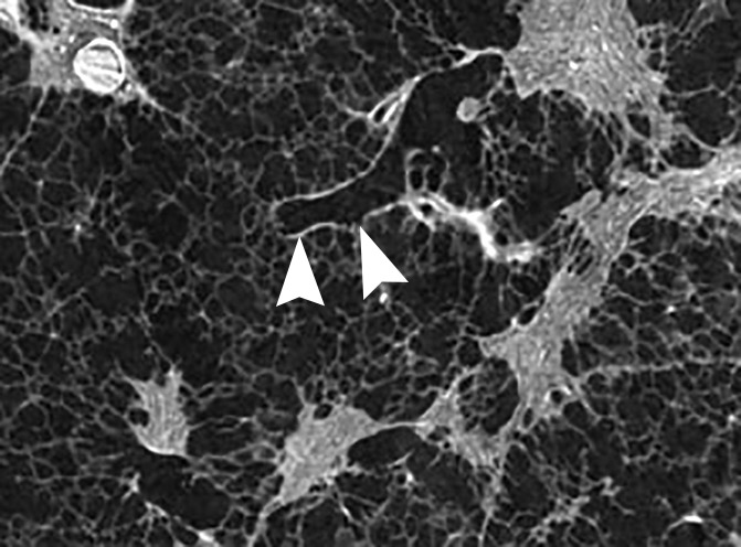
Images show the reticular pattern. (a) CT image of the upper part of lung 8. Linear opacities organized as an interrupted reticular pattern can be seen (white ○). Scale bar = 1 cm. (b) Micro-CT image shows contours of the secondary pulmonary lobule (arrowheads) with a terminal bronchiole and accompanying vessel in the center (white arrow). Linear opacities in a correlate with small islands of increased attenuation (black arrows) adjacent to interlobular septa (arrowheads) in b. Scale bar = 1 mm. (c–e) Close-up images of the outlined area in b. A terminal bronchiole (arrowheads) divides into two first-generation respiratory bronchioles (white arrows). The inferior bronchiole divides into two second-generation respiratory bronchioles (black arrows) that abruptly terminate against an irregular island of increased attenuation.
Figure 5e:
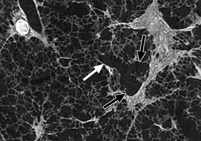
Images show the reticular pattern. (a) CT image of the upper part of lung 8. Linear opacities organized as an interrupted reticular pattern can be seen (white ○). Scale bar = 1 cm. (b) Micro-CT image shows contours of the secondary pulmonary lobule (arrowheads) with a terminal bronchiole and accompanying vessel in the center (white arrow). Linear opacities in a correlate with small islands of increased attenuation (black arrows) adjacent to interlobular septa (arrowheads) in b. Scale bar = 1 mm. (c–e) Close-up images of the outlined area in b. A terminal bronchiole (arrowheads) divides into two first-generation respiratory bronchioles (white arrows). The inferior bronchiole divides into two second-generation respiratory bronchioles (black arrows) that abruptly terminate against an irregular island of increased attenuation.
Figure 5d:
Images show the reticular pattern. (a) CT image of the upper part of lung 8. Linear opacities organized as an interrupted reticular pattern can be seen (white ○). Scale bar = 1 cm. (b) Micro-CT image shows contours of the secondary pulmonary lobule (arrowheads) with a terminal bronchiole and accompanying vessel in the center (white arrow). Linear opacities in a correlate with small islands of increased attenuation (black arrows) adjacent to interlobular septa (arrowheads) in b. Scale bar = 1 mm. (c–e) Close-up images of the outlined area in b. A terminal bronchiole (arrowheads) divides into two first-generation respiratory bronchioles (white arrows). The inferior bronchiole divides into two second-generation respiratory bronchioles (black arrows) that abruptly terminate against an irregular island of increased attenuation.
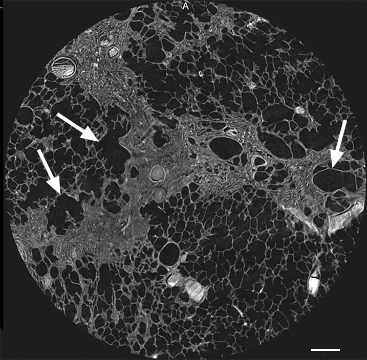
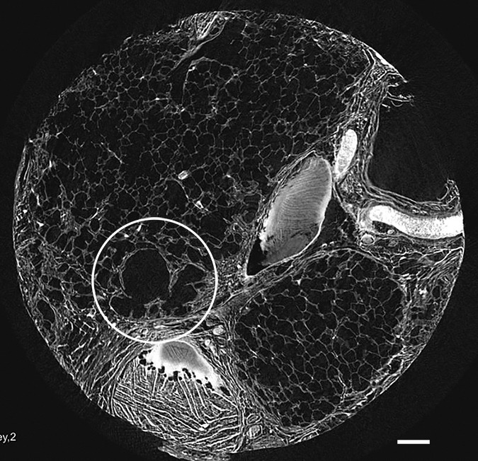
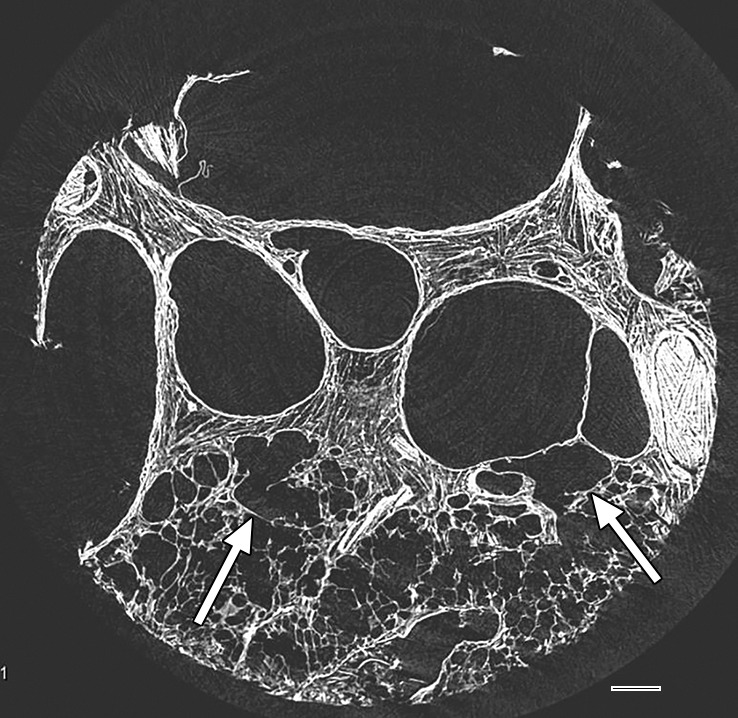
When an obvious reticular pattern is seen on CT images (Fig 6a), micro-CT images show the opacities have become larger and broader and are interconnected, resulting in broader bands that follow the course of the interlobular septa (Fig 6b).
Figure 6a:
Images show reticular pattern and cystic changes. (a) CT image of lung 1 shows reticular pattern at the periphery of the middle part of the lung. At this level, the core is taken (white ○) where the three linear opacities meet. Scale bar = 1 cm. (b) Micro-CT image shows that these linear opacities represent opaque bands along what is expected to be the interlobular septa. There is minimal to no traction on the surrounding structures; however, several irregular cystic structures can be seen. Some of these are adjacent to and some are in the opaque bands (arrows). Scale bar = 1 mm.
Figure 6b:
Images show reticular pattern and cystic changes. (a) CT image of lung 1 shows reticular pattern at the periphery of the middle part of the lung. At this level, the core is taken (white ○) where the three linear opacities meet. Scale bar = 1 cm. (b) Micro-CT image shows that these linear opacities represent opaque bands along what is expected to be the interlobular septa. There is minimal to no traction on the surrounding structures; however, several irregular cystic structures can be seen. Some of these are adjacent to and some are in the opaque bands (arrows). Scale bar = 1 mm.
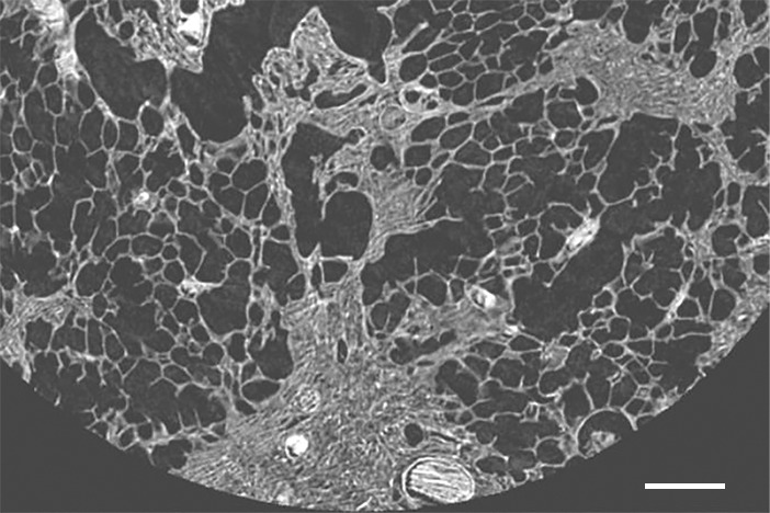
A striking finding is that in some cores, an important distortion of the alveoli and airways is found (Fig 7); however, in other cores, the architecture remains relatively undistorted, even when the opaque islands have grown into bands along the interlobular septa (Fig 6).
Figure 7:
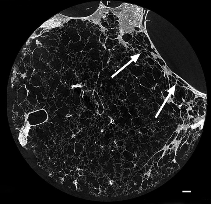
Micro-CT image of a core from lung 4 shows reticular pattern and cystic changes. Islands and bands of increased attenuation (white arrows) are seen along the interlobular septa. Nearby alveolar structures show distortion (black arrow), possibly due to radial forces exerted on them by the opacities.
A common feature in these cores with islands of increased attenuation is the presence of abnormal irregular air-containing structures in and near these opaque islands (Figs 6, 8a–8c). The presence of these air-containing structures is independent of the size of the opaque islands. They can be observed early on, when only small islands of increased attenuation are seen. They can be seen as small cysts on CT images (Fig 3) but are often beyond the resolution of this technique.
Figure 8a:
Micro-CT images of a core from lungs (a) 1, (b) 4, and (c) 7 show cystic changes. Deformed cystic structures (white ○) are seen against and in islands or bands of increased attenuation located along the interlobular septa. Scale bar = 1 mm.
Figure 8c:
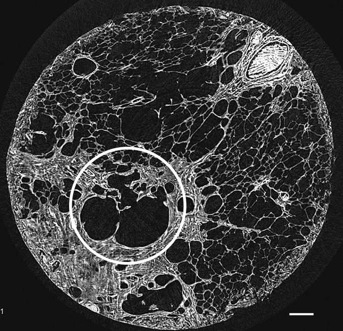
Micro-CT images of a core from lungs (a) 1, (b) 4, and (c) 7 show cystic changes. Deformed cystic structures (white ○) are seen against and in islands or bands of increased attenuation located along the interlobular septa. Scale bar = 1 mm.
Figure 8b:
Micro-CT images of a core from lungs (a) 1, (b) 4, and (c) 7 show cystic changes. Deformed cystic structures (white ○) are seen against and in islands or bands of increased attenuation located along the interlobular septa. Scale bar = 1 mm.
Overt Cyst Formation or Honeycombing
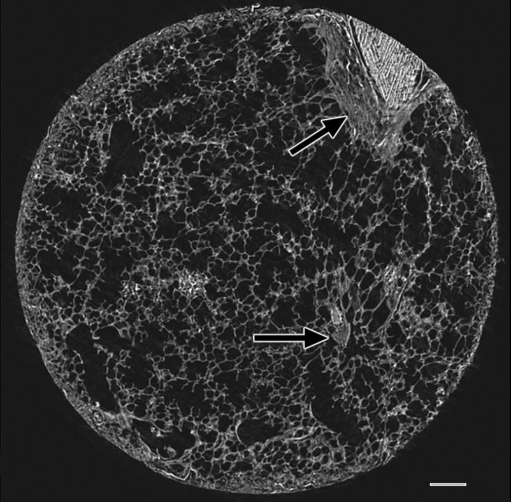
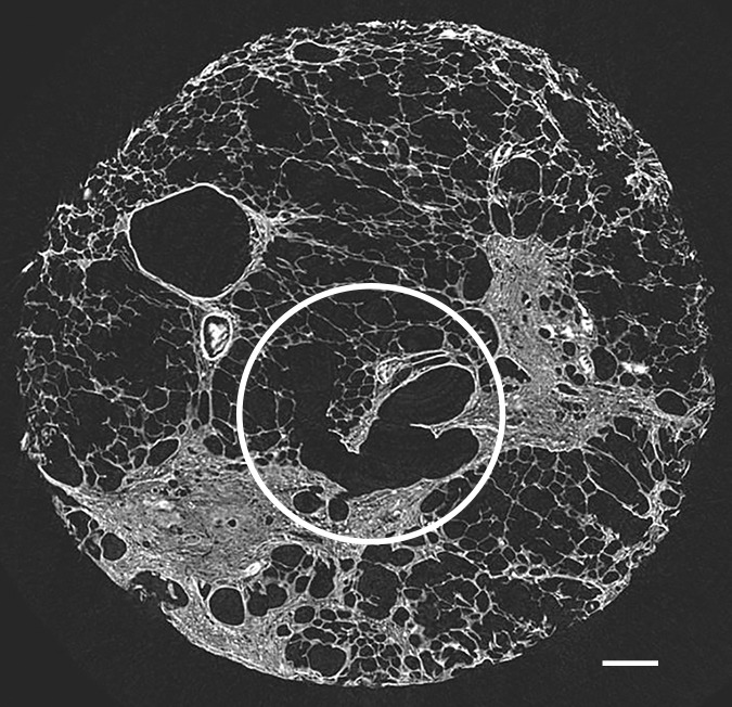
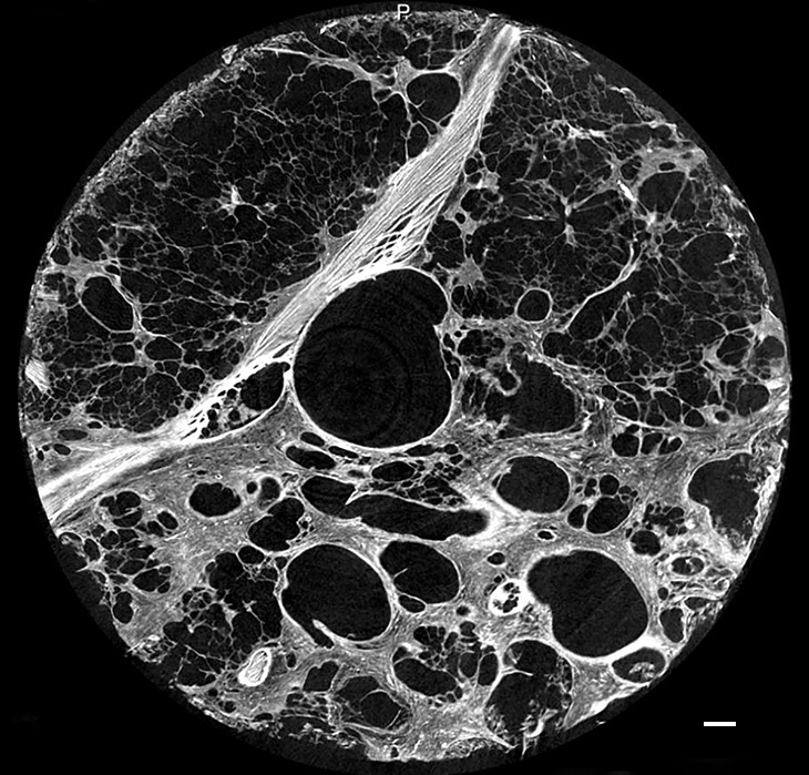
In the areas of the lung that are usually described as showing honeycombing with traction bronchiectasis at CT, the normal lung architecture and the secondary pulmonary lobule are hardly recognizable or are unrecognizable at micro-CT. Normal structures seem to be replaced by entirely opaque areas containing traction bronchiectasis and multiple cystic structures, of which only the largest are visible at CT (Figs 9, 10). The cystic structures sometimes can be followed throughout the core and seem to be connected with each other and are in continuity with the bronchial tree.
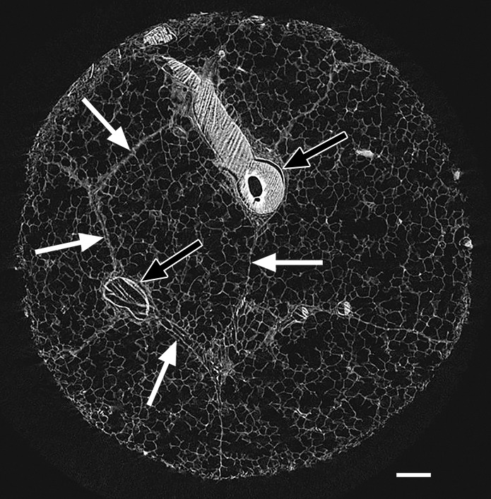
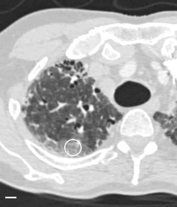
Figure 9a:
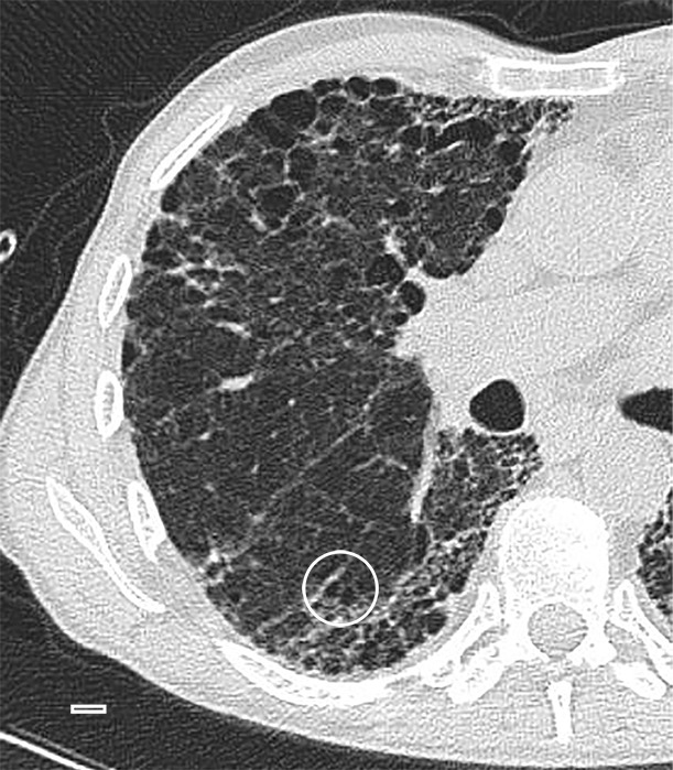
Images show overt cyst formation and honeycombing. (a) CT image of the middle part of lung 8. The core is taken at a transition area between the less involved tissue and heavily involved and distorted lung tissue. A distorted region with inlying cysts along a blood vessel is shown at the center of the white ○. Scale bar = 1 cm. (b) Micro-CT image shows a large area of increased attenuation containing multiple cysts. The cysts are better depicted at micro-CT, as only the larger cysts are visible at CT. Scale bar = 1 mm.
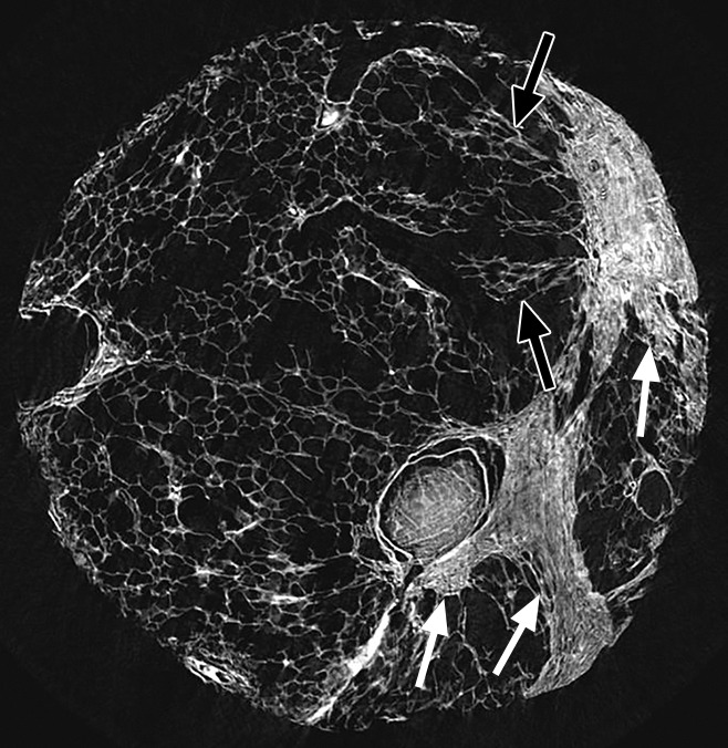
Figure 10a:
Images show overt cyst formation and honeycombing. (a) CT image at the base of lung 8 shows cysts of different sizes in the periphery. (b) Micro-CT image shows the same changes as in Figure 9 but with more and larger cysts. Adjacent to these cysts are areas of distorted alveoli and bronchioles (arrows). Scale bar = 1 mm.
Figure 10b:
Images show overt cyst formation and honeycombing. (a) CT image at the base of lung 8 shows cysts of different sizes in the periphery. (b) Micro-CT image shows the same changes as in Figure 9 but with more and larger cysts. Adjacent to these cysts are areas of distorted alveoli and bronchioles (arrows). Scale bar = 1 mm.
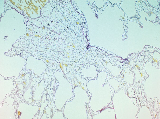
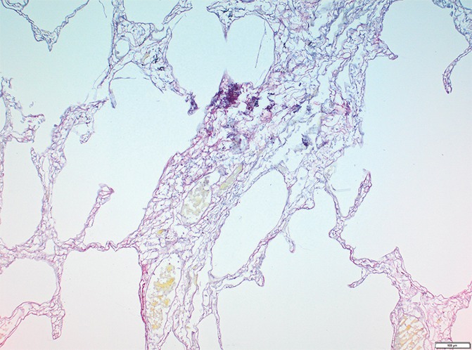
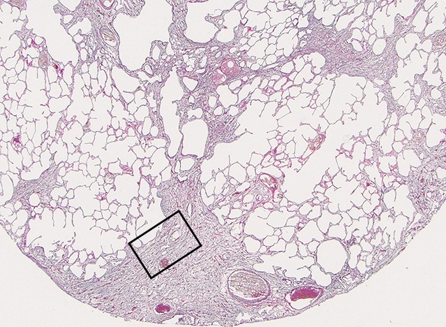
Picrosirius red staining of a slice with these opaque areas (Fig 11) shows abnormal tissue with fine reticular green and yellow fibers at polarizing microscopy, corresponding with young immature collagen.
Figure 11a:
Images show overt cyst formation and honeycombing. (a) Micro-CT image of a core from lung 1.Scale bar = 1 mm. (b) Photomicrograph of the slice corresponding to a. (Hematoxylin-eosin stain; original magnification, ×12.) (c, d) Photomicrographs of the same slice (c) without and (d) with polarized light. A fine reticular network of green and yellow fibers is seen, compatible with young collagen fibers. (Picrosirius red stain; original magnification, ×100.)
Figure 11b:
Images show overt cyst formation and honeycombing. (a) Micro-CT image of a core from lung 1.Scale bar = 1 mm. (b) Photomicrograph of the slice corresponding to a. (Hematoxylin-eosin stain; original magnification, ×12.) (c, d) Photomicrographs of the same slice (c) without and (d) with polarized light. A fine reticular network of green and yellow fibers is seen, compatible with young collagen fibers. (Picrosirius red stain; original magnification, ×100.)
Figure 11c:
Images show overt cyst formation and honeycombing. (a) Micro-CT image of a core from lung 1.Scale bar = 1 mm. (b) Photomicrograph of the slice corresponding to a. (Hematoxylin-eosin stain; original magnification, ×12.) (c, d) Photomicrographs of the same slice (c) without and (d) with polarized light. A fine reticular network of green and yellow fibers is seen, compatible with young collagen fibers. (Picrosirius red stain; original magnification, ×100.)
Figure 11d:
Images show overt cyst formation and honeycombing. (a) Micro-CT image of a core from lung 1.Scale bar = 1 mm. (b) Photomicrograph of the slice corresponding to a. (Hematoxylin-eosin stain; original magnification, ×12.) (c, d) Photomicrographs of the same slice (c) without and (d) with polarized light. A fine reticular network of green and yellow fibers is seen, compatible with young collagen fibers. (Picrosirius red stain; original magnification, ×100.)
UIP is known for its patchy geographic distribution, with alternating normal and diseased regions in different stage of disease (1,2). This is a histologic feature that also can be recognized at CT. CT images (Figs 9a, 12a) show a clear interface between what looks like a normal lung area and a predominantly cystic damaged lung region. This is confirmed at micro-CT (Figs 9b, 12b); however, there is already some architectural distortion of alveolar structures adjacent to the large cysts.
Figure 12a:
Interface between normal and cystic lung areas at CT. (a) CT image of the middle-upper part of lung 8 shows a clear-cut interface between a normal area and a predominantly cystic region. This is a typical finding in patients with IPF. (b) Micro-CT image shows what seems to be architectural distortion or compression of alveolar structures adjacent to the large cysts (arrows). Scale bar = 1 mm.
Figure 9b:
Images show overt cyst formation and honeycombing. (a) CT image of the middle part of lung 8. The core is taken at a transition area between the less involved tissue and heavily involved and distorted lung tissue. A distorted region with inlying cysts along a blood vessel is shown at the center of the white ○. Scale bar = 1 cm. (b) Micro-CT image shows a large area of increased attenuation containing multiple cysts. The cysts are better depicted at micro-CT, as only the larger cysts are visible at CT. Scale bar = 1 mm.
Figure 12b:
Interface between normal and cystic lung areas at CT. (a) CT image of the middle-upper part of lung 8 shows a clear-cut interface between a normal area and a predominantly cystic region. This is a typical finding in patients with IPF. (b) Micro-CT image shows what seems to be architectural distortion or compression of alveolar structures adjacent to the large cysts (arrows). Scale bar = 1 mm.
Discussion
The geographic evolution of fibrosis in patients with IPF is largely unknown at this moment. Micro-CT was used to study progression of lung changes caused by IPF to better understand the CT features of this chronic lung disease. The sequence of CT lung changes is well known from previous in vivo CT studies. Akira et al (22) studied serial CT findings in patients with IPF and saw areas of ground-glass opacity turn into areas of reticulation and end with cystic changes. We examined different lung regions that showed different CT features that likely correspond with different stages of disease, as is typical of a heterogeneous disorder.
A first observation was that in areas with no or minimal abnormalities at CT, a few islands of increased attenuation that are beyond the resolution of CT can already be seen at micro-CT. This enables us to confirm previous findings that patients with pathology-proven IPF can present without the typical CT findings (23).
Pure ground-glass opacity, which can be seen retrospectively in patients with very early stages of IPF, was not frequently observed in the explanted lungs in our study. It is very likely that this was because these patients underwent transplantation due to end-stage IPF. Most ground-glass opacity that we observed was located in the more-affected regions and corresponded with very opaque areas on micro-CT images that were probably overt fibrotic changes. One core taken in a ground-glass area at the periphery of the lung with no overt fibrotic changes showed only some islands of increased attenuation that were too minor to be responsible for the global increased atenuation on CT images. A possible explanation is that the ground-glass opacity seen on CT images is the result of hypoventilation in the dorsal area.
The reticular pattern on CT images was related to the presence of more of these islands of increased atenuation that were arranged at the periphery of the secondary pulmonary lobule, and it probably represents a later stage of the disease. In some cores, cystic structures arising in and near these opaque islands were seen corresponding with small cysts on CT images. These abnormal cystic structures look similar to the tridimensional photographic reconstructions of “honeycomb lungs” that Pimentel made in 1967 (24) and we think that these can be the precursors of the honeycomb cysts seen on CT images. In addition, in several cores, micro-CT revealed small cystic structures that were also located in and around the opacities at the periphery of the pulmonary lobule but that were not visible at CT; these structures very likely corresponded to microscopic honeycombing (Fig 8a–8c). Honeycombing seems to be caused by progressive enlargement of these cystic tissue opacities that gradually extend toward the centrilobular region and finally replace the entire lobule.
Micro-CT was used as an intermediate imaging step between submacroscopic CT imaging, and histologic microscopy enables a better correlation between the lung changes seen with both techniques. Histologic analysis at the different stages shows that in the early stage, the islands of increased attenuation correspond to areas of abnormal tissue with inlying young collagen, which are probably fibroblastic foci. Near these islands or foci, thick bundles of strongly polarizing collagen were seen. They look exactly like the native collagen in the alveolar wall but with an unusual parallel organization. In the lungs, we expect to find fine bundles of polarizing native collagen in the alveolar walls and interstitial space. The fact that they are in the immediate vicinity of each other and have the same orientation indicates increased approximation of alveolar walls, suggesting alveolar collapse. In the more advanced stages, these strongly polarizing collagen fibers are no longer seen, suggesting destruction of native alveolar structures and replacement by a fine reticular network of young collagen. This is typically seen in patients with granulation tissue or early scar formation.
Much remains to be uncovered about the pathogenesis of IPF. An older hypothesis is that chronic inflammation plays a major role in this pathogenesis and that alveolar damage may be the trigger for the fibroproliferative process (25). However, the current paradigm states that it is not the inflammation itself but the epithelial damage that plays a crucial role in the pathogenesis of IPF (26–28). In 1988, Myers and Katzenstein (29) suggested that alveolar collapse after epithelial damage could be an important factor in lung remodeling. In fact, it is quite similar to epithelial damage to the airway wall, which could also lead to airway collapse or obliteration, as was recently proved by Verleden et al (12) in patients with bronchiolitis obliterans syndrome. Lately, unifying theories have been provided by Leslie (30) and Chilosi et al (31), suggesting that IPF is a disease of the aging lung, wherein chronic repetitive mechanical stress is exerted on regions prone to collapse in patients with a certain predilection. Recently, Lutz et al (32) stated that irreversible collapse is an important mechanism in lung injury and fibrosis.
In this study, there are elements on micro-CT images and of the histologic analysis that support the alveolar collapse theory. We saw respiratory bronchioles terminating against the islands of increased attenuation and strands of polarizing mature collagen bundles approximating each other, both of which are indicative of tissue loss. This might be the trigger for the process of fibroproliferation, wherein normal native collagen is replaced by young immature collagen, seen as a change of birefringence under polarized light. Second, when alveolar structures collapse, there might be traction on the surrounding lung structures, resulting in bronchiectasis and the development of distorted cystic structures, which are seen in the periphery of the secondary pulmonary lobule near the areas of increased attenuation. As this process continues, there may be both increasing fibrosis and destruction of airways and airspaces with collapse, resulting in the typical image of IPF with macroscopic bronchiectasis and honeycombing.
Our results add to the understanding of the evolution of IPF. We succeeded at showing what we believe are different stages of IPF on micro-CT images, and we were able to correlate them with the findings on CT images. The way the different disease components relate to the secondary pulmonary lobule also was depicted nicely.
Our study had limitations. First, it is unavoidable that some changes might have been introduced by the way the lung specimens were processed and by the way the tissue cores were prepared. In particular, the freezing process might cause artifacts to the tissue. That is why histologic examination of these cores looks different from pathologic UIP specimens obtained via biopsy. Second, we obtained samples from only a small section of the cores, so these results need to be confirmed with larger studies.
In conclusion, our study provides direct evidence that disease in patients with IPF starts preferentially at the periphery of the secondary pulmonary lobule and grows inward, as was suggested in an indirect manner before (33,34). We saw abnormal cystic airway structures in the periphery of the secondary pulmonary lobule, and we believe that these are the precursors of honeycombing.
There are elements in this study that suggest the presence of alveolar collapse in an early stage when there is only little fibrosis. This supports the theory that alveolar collapse might be the initial trigger for the fibroproliferative process in patients with IPF.
Advances in Knowledge
■ Micro-CT has been shown to be a good tool with which to investigate parenchymal lung changes in patients with idiopathic pulmonary fibrosis (IPF) and can act as the until-now missing bridge between thin-section CT and histologic analysis (observed in 94 cores obtained from nine patients).
■ The process of lung fibrosis in patients with IPF seems to start preferentially at the periphery of the secondary pulmonary lobule and grows inward when the disease progresses (observed in lung areas showing minimal changes and in areas with a reticular pattern at CT).
■ This study supports the theory that alveolar collapse might be the initial trigger for the fibroproliferative process in patients with IPF (observation of strands of polarizing mature collagen bundles approximating each other).
Received November 6, 2015; revision requested December 17; revision received May 27, 2016; accepted July 12; final version accepted July 28.
Supported by Fonds Wetenschappelijk Onderzoek (12G8715N, C24/15/30, G3C0494), Research Foundation Flanders (12G8715N, G3C0494), and National Institutes of Health (R01 HL127349-01).
Disclosures of Conflicts of Interest: C.M. disclosed no relevant relationships. S.E.V. disclosed no relevant relationships. J.E.M. disclosed no relevant relationships. S.W. disclosed no relevant relationships. W.D.W. disclosed no relevant relationships. J.C. disclosed no relevant relationships. A.D. disclosed no relevant relationships. D.E.V.R. disclosed no relevant relationships. E.K.V. disclosed no relevant relationships. G.M.V. disclosed no relevant relationships. J.C.H. disclosed no relevant relationships. B.M.V. disclosed no relevant relationships. W.A.W. Activities related to the present article: disclosed no relevant relationships. Activities not related to the present article: received grants to attend a meeting from Roche and Boehringer Ingelheim. Other relationships: disclosed no relevant relationships. J.A.V. disclosed no relevant relationships.
Abbreviations:
- IPF
- idiopathic pulmonary fibrosis
- UIP
- usual interstitial pneumonia
References
- 1.American Thoracic Society; European Respiratory Society . American Thoracic Society/European Respiratory Society International Multidisciplinary Consensus Classification of the Idiopathic Interstitial Pneumonias. This joint statement of the American Thoracic Society (ATS), and the European Respiratory Society (ERS) was adopted by the ATS board of directors, June 2001 and by the ERS Executive Committee, June 2001. Am J Respir Crit Care Med 2002;165(2):277–304. [Published correction appears in Am J Respir Crit Care Med 2002;166(3):426.] [DOI] [PubMed] [Google Scholar]
- 2.Travis WD, Costabel U, Hansell DM, et al. An official American Thoracic Society/European Respiratory Society statement: Update of the international multidisciplinary classification of the idiopathic interstitial pneumonias. Am J Respir Crit Care Med 2013;188(6):733–748. [DOI] [PMC free article] [PubMed] [Google Scholar]
- 3.Walsh SL, Hansell DM. High-resolution CT of interstitial lung disease: a continuous evolution. Semin Respir Crit Care Med 2014;35(1):129–144. [DOI] [PubMed] [Google Scholar]
- 4.Raghu G, Collard HR, Egan JJ, et al. An official ATS/ERS/JRS/ALAT statement: idiopathic pulmonary fibrosis—evidence-based guidelines for diagnosis and management. Am J Respir Crit Care Med 2011;183(6):788–824. [DOI] [PMC free article] [PubMed] [Google Scholar]
- 5.Mathieson JR, Mayo JR, Staples CA, Müller NL. Chronic diffuse infiltrative lung disease: comparison of diagnostic accuracy of CT and chest radiography. Radiology 1989;171(1):111–116. [DOI] [PubMed] [Google Scholar]
- 6.Tung KT, Wells AU, Rubens MB, Kirk JM, du Bois RM, Hansell DM. Accuracy of the typical computed tomographic appearances of fibrosing alveolitis. Thorax 1993;48(4):334–338. [DOI] [PMC free article] [PubMed] [Google Scholar]
- 7.Swensen SJ, Aughenbaugh GL, Myers JL. Diffuse lung disease: diagnostic accuracy of CT in patients undergoing surgical biopsy of the lung. Radiology 1997;205(1):229–234. [DOI] [PubMed] [Google Scholar]
- 8.Flaherty KR, Andrei AC, King TE, Jr, et al. Idiopathic interstitial pneumonia: do community and academic physicians agree on diagnosis? Am J Respir Crit Care Med 2007;175(10):1054–1060. [DOI] [PMC free article] [PubMed] [Google Scholar]
- 9.Gruden JF, Panse PM, Leslie KO, Tazelaar HD, Colby TV. UIP diagnosed at surgical lung biopsy, 2000-2009: HRCT patterns and proposed classification system. AJR Am J Roentgenol 2013;200(5):W458–W467. [DOI] [PubMed] [Google Scholar]
- 10.Raghu G, Lynch D, Godwin JD, et al. Diagnosis of idiopathic pulmonary fibrosis with high-resolution CT in patients with little or no radiological evidence of honeycombing: secondary analysis of a randomised, controlled trial. Lancet Respir Med 2014;2(4):277–284. [DOI] [PubMed] [Google Scholar]
- 11.McDonough JE, Yuan R, Suzuki M, et al. Small-airway obstruction and emphysema in chronic obstructive pulmonary disease. N Engl J Med 2011;365(17):1567–1575. [DOI] [PMC free article] [PubMed] [Google Scholar]
- 12.Verleden SE, Vasilescu DM, Willems S, et al. The site and nature of airway obstruction after lung transplantation. Am J Respir Crit Care Med 2014;189(3):292–300. [DOI] [PubMed] [Google Scholar]
- 13.Bray DF, Bagu J, Koegler P. Comparison of hexamethyldisilazane (HMDS), Peldri II, and critical-point drying methods for scanning electron microscopy of biological specimens. Microsc Res Tech 1993;26(6):489–495. [DOI] [PubMed] [Google Scholar]
- 14.de Jong PA, Vos R, Verleden GM, Vanaudenaerde BM, Verschakelen JA. Thin-section computed tomography findings before and after azithromycin treatment of neutrophilic reversible lung allograft dysfunction. Eur Radiol 2011;21(12):2466–2474. [DOI] [PMC free article] [PubMed] [Google Scholar]
- 15.Hansell DM, Bankier AA, MacMahon H, McLoud TC, Müller NL, Remy J. Fleischner Society: glossary of terms for thoracic imaging. Radiology 2008;246(3):697–722. [DOI] [PubMed] [Google Scholar]
- 16.Van de Casteele E, Slagmolen P, Willems S, et al. Multiscale Lung Imaging. Skyscan Web site. http://www.skyscan.be/company/usersmeeting2012a.htm. Presented at the Annual MicroCT Users Meeting, Brussels, Belgium, April 3–5, 2012. Accessed March 2014.
- 17.Junqueira LC, Bignolas G, Brentani RR. Picrosirius staining plus polarization microscopy, a specific method for collagen detection in tissue sections. Histochem J 1979;11(4):447–455. [DOI] [PubMed] [Google Scholar]
- 18.Wolman M, Gillman T. A polarized light study of collagen in dermal wound healing. Br J Exp Pathol 1972;53(2):85–89. [PMC free article] [PubMed] [Google Scholar]
- 19.Wolman M. Polarized light microscopy as a tool of diagnostic pathology. J Histochem Cytochem 1975;23(1):21–50. [DOI] [PubMed] [Google Scholar]
- 20.Sumikawa H, Johkoh T, Ichikado K, et al. Usual interstitial pneumonia and chronic idiopathic interstitial pneumonia: analysis of CT appearance in 92 patients. Radiology 2006;241(1):258–266. [DOI] [PubMed] [Google Scholar]
- 21.Devaraj A. Imaging: how to recognise idiopathic pulmonary fibrosis. Eur Respir Rev 2014;23(132):215–219. [DOI] [PMC free article] [PubMed] [Google Scholar]
- 22.Akira M, Sakatani M, Ueda E. Idiopathic pulmonary fibrosis: progression of honeycombing at thin-section CT. Radiology 1993;189(3):687–691. [DOI] [PubMed] [Google Scholar]
- 23.Orens JB, Kazerooni EA, Martinez FJ, et al. The sensitivity of high-resolution CT in detecting idiopathic pulmonary fibrosis proved by open lung biopsy. a prospective study. Chest 1995;108(1):109–115. [DOI] [PubMed] [Google Scholar]
- 24.Pimentel JC. Tridimensional photographic reconstruction in a study of the pathogenesis of honeycomb lung. Thorax 1967;22(5):444–452. [DOI] [PMC free article] [PubMed] [Google Scholar]
- 25.Keogh BA, Crystal RG. Alveolitis: the key to the interstitial lung disorders. Thorax 1982;37(1):1–10. [DOI] [PMC free article] [PubMed] [Google Scholar]
- 26.Adamson IY, Young L, Bowden DH. Relationship of alveolar epithelial injury and repair to the induction of pulmonary fibrosis. Am J Pathol 1988;130(2):377–383. [PMC free article] [PubMed] [Google Scholar]
- 27.Selman M, King TE, Pardo A; American Thoracic Society; European Respiratory Society; American College of Chest Physicians . Idiopathic pulmonary fibrosis: prevailing and evolving hypotheses about its pathogenesis and implications for therapy. Ann Intern Med 2001;134(2):136–151. [DOI] [PubMed] [Google Scholar]
- 28.Pardo A, Selman M. Idiopathic pulmonary fibrosis: new insights in its pathogenesis. Int J Biochem Cell Biol 2002;34(12):1534–1538. [DOI] [PubMed] [Google Scholar]
- 29.Myers JL, Katzenstein AL. Epithelial necrosis and alveolar collapse in the pathogenesis of usual interstitial pneumonia. Chest 1988;94(6):1309–1311. [DOI] [PubMed] [Google Scholar]
- 30.Leslie KO. Idiopathic pulmonary fibrosis may be a disease of recurrent, tractional injury to the periphery of the aging lung: a unifying hypothesis regarding etiology and pathogenesis. Arch Pathol Lab Med 2012;136(6):591–600. [DOI] [PubMed] [Google Scholar]
- 31.Chilosi M, Carloni A, Rossi A, Poletti V. Premature lung aging and cellular senescence in the pathogenesis of idiopathic pulmonary fibrosis and COPD/emphysema. Transl Res 2013;162(3):156–173. [DOI] [PubMed] [Google Scholar]
- 32.Lutz D, Gazdhar A, Lopez-Rodriguez E, et al. Alveolar derecruitment and collapse induration as crucial mechanisms in lung injury and fibrosis. Am J Respir Cell Mol Biol 2015;52(2):232–243. [DOI] [PubMed] [Google Scholar]
- 33.Livingstone JL, Lewis JG, Reid L, Jefferson KE. Diffuse interstitial pulmonary fibrosis. a clinical, radiological, and pathological study based on 45 patients. Q J Med 1964;33:71–103. [PubMed] [Google Scholar]
- 34.Nishimura K, Kitaichi M, Izumi T, Nagai S, Kanaoka M, Itoh H. Usual interstitial pneumonia: histologic correlation with high-resolution CT. Radiology 1992;18(2):337–342. [DOI] [PubMed] [Google Scholar]