Abstract
RF/microwave soft magnetic films (SMFs) are key materials for miniaturization and multifunctionalization of monolithic microwave integrated circuits (MMICs) and their components, which demand that the SMFs should have higher self-bias ferromagnetic resonance frequency fFMR, and can be fabricated in an IC compatible process. However, self-biased metallic SMFs working at X-band or higher frequency were rarely reported, even though there are urgent demands. In this paper, we report an IC compatible process with two-step superposition to prepare SMFs, where the FeCoB SMFs were deposited on (011) lead zinc niobate–lead titanate substrates using a composition gradient sputtering method. As a result, a giant magnetic anisotropy field of 1498 Oe, 1–2 orders of magnitude larger than that by conventional magnetic annealing method, and an ultrahigh fFMR of up to 12.96 GHz reaching Ku-band, were obtained at zero magnetic bias field in the as-deposited films. These ultrahigh microwave performances can be attributed to the superposition of two effects: uniaxial stress induced by composition gradient and magnetoelectric coupling. This two-step superposition method paves a way for SMFs to surpass X-band by two-step or multi-step, where a variety of magnetic anisotropy field enhancing methods can be cumulated together to get higher ferromagnetic resonance frequency.
Nowadays integration circuit (IC) technology is developing from system-in-package towards system-on-chip, so the integration of the passive components, such as inductors and capacitors, on one chip is usually adapted in order to miniaturize the electromagnetic devices and to increase the data transmission rate1,2. Microwave soft magnetic films (SMFs) are key materials, which can effectively miniaturize and multifunctionalize the electromagnetic components and devices, such as filters, phase shifters, isolators, circulators, thin film wireless inductors, magnetic recording write heads, antennas, etc.3,4,5,6, and reduce their occupation area in MMIC boards. Modern electronic products are heading towards high density, high-frequency, frequency tunability, lightweight and low energy consumption, etc., which give rise to increasing demands for microwave SMFs. Microwave SMFs should have higher ferromagnetic resonance (FMR) frequency (fFMR) and frequency tunability, high permeability, and are to be fabricated in an IC compatible process. In order to reduce the weight and energy consumption of MMICs, researchers are trying to make magnetic devices to be clocked under no magnetic field7, i.e. the magnetic properties are manipulated by non-magnetic field methods, such as stress, magnetoelectric coupling, magnetoelastic coupling, etc. instead of bulky and power-consuming electromagnets. Soft magnetic ferrites are not sufficient for MMIC devices due to their lower saturation magnetization (4πMS) and permeability, and especially the high fabrication temperature which is incompatible with the IC process8. However, metallic soft magnetic films exhibit special advantages in MMIC devices since they have higher 4πMS and permeability, and good compatibility with the IC fabrication process. Therefore, self-biased metallic SMFs prepared at IC compatible process have drawn an increasing attention9,10,11. It was reported that the metallic SMFs are able to operate at S-band (2–4 GHz) or C-band (4–8 GHz) under self-bias condition12,13. However, to the best of our knowledge, self-biased magnetic films working at Ku-band (12–18 GHz) have not been reported, even though there are urgent needs in achieving tunablility in MMICs used in radar, aircraft, satellite, portable communication products, etc.
In this paper, we choose Fe70Co30-B alloys with high 4πMS and permeability, and demonstrate a novel method to prepare microwave SMFs at room temperature (an IC compatible process). The novel preparation method combined two magnetic anisotropy fields HK together (i.e. stress induced HK by composition gradient and electric field induced tunable HK via magnetoelectric coupling), realizing a two-step climbing of ferromagnetic resonance frequency. As a result, a giant HK of 1498 Oe, which is 1–2 orders of magnitude larger than that by conventional magnetic annealing method, and a record high fFMR of up to 12.96 GHz, reaching Ku-band, were obtained at zero magnetic bias field and bias electric field of 8 kVcm−1 in the as-deposited Fe70Co30-B/lead zinc niobate–lead titanate (PZN-PT) (hereinafter referred to as FeCoB/PZN-PT) multiferroic heterostructure films. The ferromagnetic resonance frequency of the FeCoB/PZN-PT multiferroic heterostructures can be manipulated by electric field, instead of large and energy-consuming electromagnets, from 6.30 GHz to 12.96 GHz with the electric field from 0 to 8 kVcm−1. The net frequency shift ΔfFMR is as high as 6.66 GHz, and the frequency tunability ΔfFMR/fFMR is about 106%, equivalent to 832.5 MHz cm kV−1. This electric field manipulation of fFMR shift has low energy consumption and lightweight, especially suitable for manufacturing tuneable MMIC devices.
The ferromagnetic resonance frequency fFMR of SMFs can be expressed by the Kittle equation as follows,
 |
where γ is the gyromagnetic ratio, 4πMS is the saturation magnetization. Clearly, high 4πMS and HK are needed to achieve a high fFMR in SMFs. Previous research on achieving high fFMR SMFs has been mostly focused on enhancing uniaxial magnetic anisotropy field HK since it is relatively easier to be enhanced by 1–2 orders of magnitude, compared to saturation magnetization that is capped at 24.5 kGs at room temperature14,15. Magnetron sputtering of SMFs in in-situ magnetic fields and/or subsequent magnetic annealing after deposition have been widely employed for inducing a uniaxial magnetic anisotropy16,17. However, the induced uniaxial magnetic anisotropy fields are usually in the range of <50 Oe, which leads to limited ferromagnetic resonance frequency of <3 GHz for most of the metallic magnetic films18.
Several different approaches have been investigated for achieving high uniaxial magnetic anisotropy in SMFs, such as oblique sputtering19,20, facing-target sputtering21, exchange coupling22,23,24,25, and magnetoelectric coupling26,27, etc. Oblique sputtering and facing-target sputtering can generate magnetic films with HK of 20–300 Oe19,20. Exchange coupling, such as antiferromagnetic/ferromagnetic exchange coupling22,23,24 and exchange coupling between magnetically soft and hard layers25, provides high HK around 100–750 Oe. In our previous work, a novel composition gradient sputtering (CGS) method was applied to achieve a high uniaxial magnetic anisotropy in SMFs28,29,30, which dramatically increased the in-plane uniaxial magnetic anisotropy field to up to 547 Oe due to the uniaxial stress distribution induced by composition gradient. As a result, good microwave ferromagnetic properties with ferromagnetic resonance frequency over 7 GHz were obtained in composition gradient deposited magnetic films.
Multiferroic composite materials have drawn an increased amount of attention recently due to the strong magnetoelectric coupling demonstrated in multiferroic composites, which allows for electric field manipulation of magnetic properties (converse magnetoelectric effect) or magnetic field control of electric polarization (direct magnetoelectric effect)31,32,33,34. The magnetoelectric coupling in magnetic/ferroelectric multiferroic heterostructures can lead to dramatically enhanced electric-field tunable magnetic anisotropy fields approaching 750–880 Oe35,36,37. Based on the discussion above, it is difficult to obtain SMFs with HK over 1000 Oe or fFMR over 10 GHz at zero biased magnetic field using a single method. It is necessary to explore novel methods to enhance HK, and therefore to push the ferromagnetic resonance to X- or Ku-band.
Results
The design for enhancing the ferromagnetic resonance frequency via CGS and magnetoelecric coupling
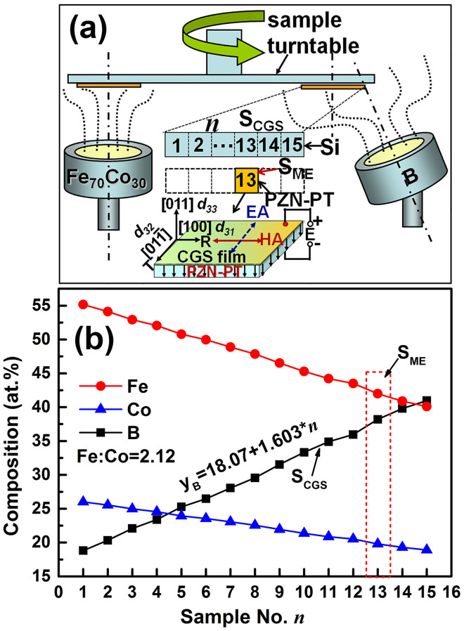
The FeCoB/PZN-PT multiferroic heterostructures were prepared by a composition gradient sputtering method. The detailed experimental procedures are described as follows: firstly, a (100) single crystal Si substrate with dimension of 75 mm × 5 mm × 0.5 mm was pasted on the turntable with the length direction along the radial (R) direction for optimizing fabrication condition of the CGS SMFs. The sample prepared by CGS method was named as SCGS. The SCGS was cut into 15 segments along the length direction with equal size of 5 mm × 5 mm for microstructure and magnetic properties measurement, and the segments were successively numbered as n = 1 to 15 from inner to outer (see the top of Figure 1a inset). Secondly, choose an optimum position (e.g. n = 13 in this study), where the comprehensive soft magnetic properties are optimum, then paste a 5 mm × 5 mm (011)-cut PZN-PT single crystal substrate on this optimum position with [100] direction of PZN-PT along the R direction (i.e. [100]//R, see the middle of the Figure 1a inset ). The CGS FeCoB film was also deposited on PZN-PT substrate under the same optimum sputtering conditions for studying the electric field manipulation of ferromagnetic resonance via magnetoelectric coupling. So it was named as SME. Therefore, the effects from composition gradient and magnetoelectric coupling on the microwave soft magnetic properties can be verified by the samples SCGS and SME, respectively.
Figure 1. The CGS device and composition distribution.
(a) The schematic drawing of composition gradient sputtering (CGS) device, and (b) the composition distribution detected by a field emission electron probe microanalyzer. The insets of Figure 1a from top to bottom shows the position distribution for CGS sample SCGS and the magnetoelectric coupling sample SME, and the interaction mechanism of magnetoelectric coupling between CGS film and PZN-PT. The composition distribution of SME is marked in the inset of Figure 1b using a red short-dashed box.
Figure 1a shows the schematic drawing of the composition gradient sputtering method. The main target of Fe70Co30 directly faces the centre of the substrate which sits on a rotating turntable, while the doping target of B is offset radially from the sample centre. The doping gun (B target) is tilted at a certain angle towards the sample turntable. This geometrical structure ensures that the materials from the Fe70Co30 main target are distributed homogeneously across the sample, while those from B doping target will have a composition gradient distribution, i.e. B concentration increases gradually from inner to outer positions along the R orientation.
The composition distribution and soft magnetic properties of CGS FeCoB/Si films
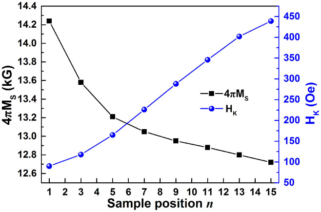
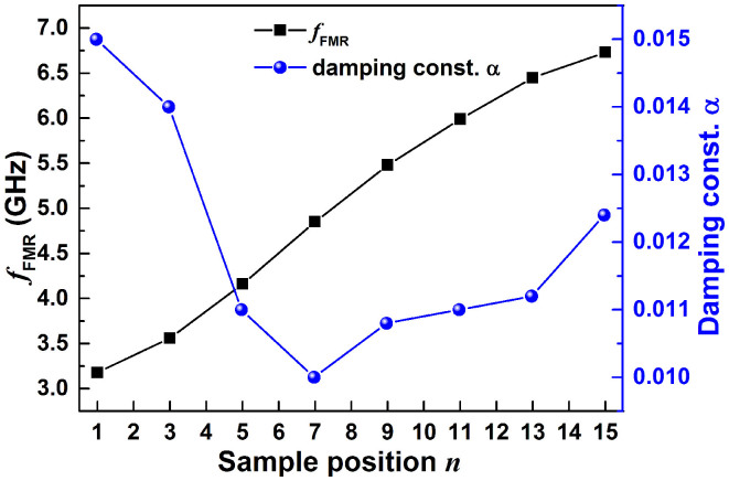
The composition distribution along R direction was detected by a field emission electron probe microanalyzer (FE-EPMA). As illustrated in Figure 1b, the atomic ratio between Fe and Co remains at 2.12, indicating a homogeneous composition comparable to the Fe70Co30 target composition; while the B composition yB increases linearly from 18.07 at.% to 42.12 at.% for the test positions from n = 1 to 15, undergoing a linear relation of yB = 18.07 + 1.603*n (see Figure 1b). This composition distribution verified the design idea of using composition gradient sputtering to create a composition gradient film with linear doping. The linear doping of B element gives rise to an almost linear increase of HK and a nonlinear decrease of saturation magnetization 4πMS. As illustrated in Figure 2, the HK of CGS FeCoB films increases almost linearly from 90 to 436 Oe, while 4πMS rapidly reduces from 14.24 kG (n = 1) to 13.21 kG (n = 5) at first, then decrease linearly towards 12.72 kG (n = 15). The HK increases nearly 5 times, while 4πMS reduces only about 10%, so the ferromagnetic resonance frequency is dominated by HK. As expected, the sample position n dependence of fFMR, shown in Figure 3, demonstrates almost the same trend in fFMR with that in HK (shown in Figure 2). With the increase of n, fFMR increases from 3.18 to 6.73 GHz with increment of 3.55 GHz, equivalent to an increase ratio of 212%. The damping constant α of the CGS FeCoB/Si samples, shown in Figure 3, decreases with the increase of n from 1 to 7, then stays on a low platform with value of 0.011 till n = 13, after that α goes up, implying an increase of magnetic loss. Considering the comprehensive magnetic properties including 4πMS, HK, fFMR, and α for the segments at different n, we chose n = 13 as an optimum position to deposit magnetoelectric coupling sample on PZN-PT substrate since sample SCGS@n = 13 shows a relatively large fFMR of 6.45 GHz, large HK of 402 Oe and low α of 0.0112.
Figure 2. Sample position n dependence of 4πMS and HK for SCGS.
Figure 3. Sample position n dependence of fFMR and damping constant α for SCGS.
Composition gradient induced uniaxial magnetic anisotropy in CGS films
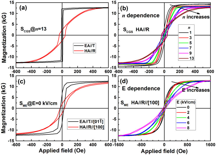
Some typical hysteresis loops of SCGS are summarized in Figure 4a and 4b. As illustrated in Figure 4a, there is an obvious uniaxial magnetic anisotropy with magnetically easy axis (EA) along tangential direction and magnetically hard axis (HA) along R direction for SCGS@n = 13. The n-dependent hysteresis loops along HA are shown in Figure 4b. It can be seen that the HK increases with the increase of n (or B doping). The detailed HK variation is shown in Figure 2. The uniaxial magnetic anisotropy in CGS films can be explained as stress gradient induced uniaxial magnetic anisotropy. The intrinsic stress in general is randomly dispersed in the magnetic films which gives rise to a high damping constant and decreasing resonant frequency. However, as reported in our previous work28,29,30, if a uniaxial stress replaces the randomly dispersed intrinsic stress, a stress-induced uniaxial magnetic anisotropy will be obtained. This uniaxial magnetic anisotropy leads to enhanced ferromagnetic resonance and improved microwave magnetic properties. The composition gradient sputtering is an effective way to induce a uniaxial stress, a high uniaxial magnetic anisotropy and an enhanced ferromagnetic resonance frequency.
Figure 4. Sample position and electric field dependent hysteresis loops for SCGS and SME.
(a) Representative hysteresis loops of SCGS@n = 13, showing an obvious uniaxial magnetization with HA along R direction; (b) the sample position n dependence of hysteresis loops along HA//R direction for SCGS; (c) the uniaxial magnetic hysteresis loops of SME@E = 0 kVcm−1; (d) the electric field dependence of hysteresis loops of SME.
Combination of stress-mediated CGS and magnetoelectric coupling, and enhancement of microwave soft magnetic properties
As described above, the composition gradient sputtering method gives rise to a compressive stress, leading to a magnetically hard axis along the radial direction. On the other hand, for a (011)-cut PZN-PT single crystal substrate, when the electric field is applied along [011] direction, compressive and tensile stresses will be generated along [100] and [01-1] directions, respectively. According to magnetoelastic energy equation  , for a positive λS (as the case in this study for the FeCoB films), a compressive or tensile stress σ will lead to a magnetic anisotropy that forces the magnetic moments to align perpendicular or parallel to the stresses direction, respectively. In other words, the magnetoelectric-coupling-induced magnetic hard axis direction is along [100] direction. So if the [100] direction is parallel to the R direction, the electric-field-tunable effective uniaxial magnetic anisotropy field (HK)ME will be parallel to the composition-gradient-induced uniaxial magnetic anisotropy field (HK)CGS. Therefore they will be combined together leading to an ultrahigh and tunable uniaxial magnetic anisotropy field HK (see the bottom of Figure 1a inset). In this study, sample position n = 13 was chosen to paste the PZN-PT substrate on, with substrate [100]//R to realize the superposition of two magnetic anisotropies. As expected, the hysteresis loops of CGS FeCoB/PZN-PT multiferroic heterostructures show a well-defined uniaxial magnetic anisotropy with a HK of 384 Oe at E = 0 kVcm−1, slightly smaller than that of 402 Oe on Si substrate (see Figure 4a and 4c). It is exciting that the HK of SME dramatically increases with the increase of electric field, and a record high HK of 1498 Oe was obtained at E = 8 kVcm−1, implying that an ultrahigh ferromagnetic resonance frequency will be achieved thanks to the combining of composition gradient sputtering and magnetoelectric coupling effect.
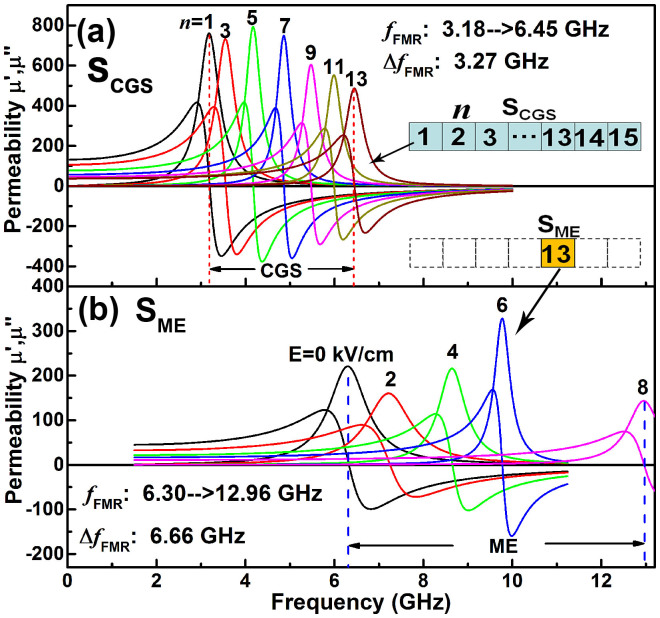
Figure 5 shows the frequency dependence of complex permeability for SCGS at various n and for SME at various electric fields. From Figure 5a, it can be seen that the CGS pushed the fFMR from 3.18 to 6.45 GHz for n from 1 to 13. When the Si substrate was replaced by a PZN-PT substrate, it was found that although the fFMR of 6.30 GHz for SME@E = 0 kVcm−1 is slightly smaller than that of SCGS@n = 13 due to the difference between the Si and PZN-PT substrates, the magnetoelectric coupling effect dramatically drives the fFMR of FeCoB/PZN-PT multiferroic heterostructures towards 12.92 GHz, directly reaching Ku-band from C-band across X-band. To the best of our knowledge, it is the first report that the ferromagnetic resonance frequency of as-deposited metallic magnetic films can reach Ku-band at zero-bias magnetic field. The magnetoelectric coupling effect in SME not only generates a 6.66 GHz shift of fFMR under an electric field of 8 kVcm−1, but also provides an electric field tunable ferromagnetic resonance frequency shift over a very broad frequency span, realizing electric field controlled frequency tuning. This is of great significance because it provides the possibility to fabricate electric field tunable microwave devices with large tunability, low energy consumption and light-weight.
Figure 5. Frequency dependence of permeability at zero magnetic field for (a) SCGS (n = 1–13) and (b) SME (E = 0–8 kVcm−1), showing the two-step climbing of fFMR by CGS and ME effects, respectively.
The electric field and composition gradient-induced ferromagnetic resonance frequency shift can be explained by the strain/stress-mediated in-plane magnetic anisotropy field. The in-plane ferromagnetic resonance frequency [Equation (1)] can be rewritten as:
 |
where (HK)CGS is the CGS-induced uniaxial magnetic anisotropic field, (HK)ME is the electric-field-induced effective magnetic field which could be positive or negative, and in this study it can be express as35,36,37,
 |
where Y is the Young's Modulus, ν is Poisson's ratio, λ is the magnetostriction constant of FeCoB film, d31 = −3000 pC N−1 along [100] and d32 = 1100 pC N−1 along [01-1] are linear anisotropic piezoelectric coefficients of PZN-PT, and E is the applied external electric field. (HK)ME is quantitatively determined by observing the ferromagnetic resonance spectrum shift under various electric fields38. From equation (3), it can be concluded that the (HK)ME is proportional to the applied electric field due to the magnetoelectric coupling effect, resulting in an electric field tunable fFMR. Similarly, the increase of (HK)CGS due to the composition gradient will give rise to an upward shift of fFMR.
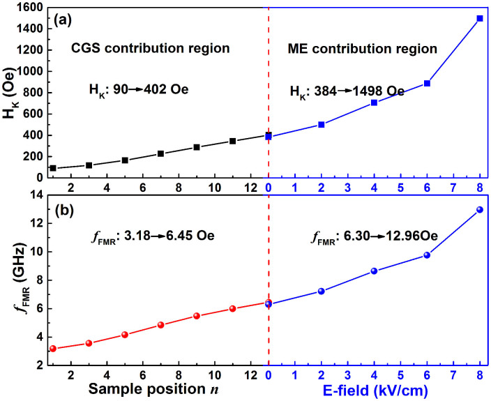
The sample position n and electric field dependence of magnetic anisotropy field HK and ferromagnetic resonance frequency fFMR are summarized in Figure 6. As illustrated, the two-step enhancement of HK and fFMR is clearly observed. Figure 6 is separated into left and right sections by a red dashed line. The left and right sections represent the contributions from composition gradient sputtering and magnetoelectric coupling effect, respectively. In the left section, with the increase of sample position n, the B concentration increases, and the HK increases linearly from 90 to 402 Oe, leading to an increase of fFMR from 3.18 to 6.45 GHz. In the right section, the CGS FeCoB film was deposited on PZN-PT substrate, and the enhancement effect of electric field on HK and fFMR begins to function in addition to the CGS effect. So the HK and fFMR are further pushed up by electric field starting from the corresponding values of SCGS. The HK and fFMR increase from 384 to 1498 Oe and from 6.30 to 12.96 GHz, respectively, with electric field from 0 to 8 kVcm−1. This two-step superposition method provides a combined effective uniaxial magnetic anisotropy field of up to 1498 Oe at 8 kVcm−1, which is 1–2 orders of magnitude higher than that by the conventional magnetic annealing method. At the same time, the fFMR also directly reaches Ku-band from C-band across X-band.
Figure 6. Sample position n and electric field dependence of (a) HK and (b) fFMR for SCGS and SME.
It is worth mentioning that the strain occurs in the magnetic films due to the composition gradient and the magnetoelectric coupling effect, so a perpendicular anisotropy may arise39. For verifying this issue, the FMR measurement for SME sample was carried out at various electric fields. In the case of an in-plane applied magnetic field and measuring FMR along the easy axis, the in-plane resonance frequency is well described by Kittle equation, as reported in Ref. 39,40,41,
 |
where 4πMeff = 4πMS –  defines the effective saturation induction,
  is the perpendicular anisotropy field H⊥, and
  is the in-plane uniaxial anisotropy field Heff ( = (HK)CGS + (HK)ME). The 4πMeff and Heff can be evaluated by fitting the f vs. Hr plots using equation (4). The fitted Heff is well consistent with the statically measured HK indicating the experimental data are well fitted using Kittle equation. The FMR fitting results demonstrate that 4πMeff with an average value of 12.37 kG is slightly smaller than 4πMS of 12.79 kG with a small difference of 420 Oe, indicating that a small perpendicular anisotropy may present in the ferromagnetic film. Comparing with the out-of-plane saturation magnetic field of more than 15 kOe, such a small perpendicular field is not enough to drive the magnetic moments to the normal direction of the film. Therefore, the magnetic moments are mainly lying in the plane.
In conclusion, a record high ferromagnetic resonance frequency of 12.92 GHz, which directly reaches Ku-band from C-band across X-band, was obtained in as-deposited CGS FeCoB/PZN-PT multiferroic heterostructures at zero bias magnetic fields due to combining the composition gradient sputtering and magnetoelectric coupling effect together. This two-step superposition method can effectively add two kinds of uniaxial magnetic anisotropy fields together, obtaining ultrahigh HK that cannot be reached with any single method. This method paves the way to get higher fFMR by two-step or multi-step method. The CGS FeCoB/PZN-PT multiferroic heterostructures exhibit ultrahigh fFMR with very broad electric field tunable frequencies, which provides great opportunities for self-biased voltage tuning microwave multiferroic components working at X-band or higher frequencies without energy consuming electromagnets. All the fabrication processes of the CGS FeCoB/PZN-PT multiferroic heterostructures are carried out at room temperature (i.e. at IC compatible process), which is very beneficial to the integration of these soft magnetic films into monolithic microwave integrated circuits.
Methods
Preparation of the FeCoB/PZN-PT multiferroic hyterestructures
The FeCoB films with average thickness of 100-nm were deposited on (100) single crystal Si substrates with dimension of 75 mm × 5 mm × 0.5 mm by composition gradient sputtering method at room temperature under 2.8 mTorr Ar atmosphere with a flow rate of 20 sccm, along with a RF power of 80 W for Fe70Co30 target and various powers from 60 to 180 W for B target. The FeCoB films deposited on Si substrate were used to measure magnetic properties, to observe microstructure, and to explore optimum deposition condition. It is found that the sputtering powers of 80 W for Fe70Co30 and 135 W for B target are the optimum deposition condition. Based on the exploring data with Si substrate (as discussed above), the optimum position is at n = 13. Afterwards, a (011)-cut single crystal PZN-PT substrate with dimension of 5 mm[100] × 5 mm[01-1] × 0.5 mm[011] was pasted at position n = 13 (see Figure 1 inset) with [100]//R, and deposited CGS FeCoB film on it under the optimum deposition condition.
Measurement of composition, magnetic, and microwave properties
The composition of films was determined by a FE-EPMA. The magnetic properties were measured by a vibrating sample magnetometer (VSM). The ferromagnetic resonance characteristics of the multiferroic heterostructures were analyzed by a broadband ferromagnetic resonance spectroscopy with the transmission line along the easy axis. The microwave performances were evaluated a vector network analyzer (VNA) with co-planar waveguide. The vector network analyzer acts as a transmitter and a receiver of microwave. The film sample was put on a specially designed co-plane waveguide transmission line fixture. When the microwave passes through the transmission line covered with the soft magnetic film, it will be absorbed by the magnetic film. As a result, the scattering parameter S21 will show an absorption peak around the ferromagnetic resonance frequency. The vector network analyzer records the scattering parameters, and simulates the measured curves with LLG (Landau-Liftshitz-Gilbert) equation. Thus, useful parameters such as permeability, ferromagnetic resonance frequency, damping constant, etc. can be obtained.
Acknowledgments
This work was financially supported by National Natural Science Foundation of China with grant No. 11074040, and Key Project of Natural Science Foundation of Shandong Province with grant No. ZR2012FZ006.
Footnotes
The authors declare no competing financial interests.
Author Contributions S.L. contributed to the conception, design of the experiment, and writing the manuscript with assistance of J.D. J.D. measured the composition of the samples. Q.X. and H.D. prepared the samples. J.X., Y.W. and Q.L. measured the microwave and magnetic properties. Y.L. analyzed the data. All authors discussed and commented on the manuscript.
References
- Yamaguchi M. et al. Microfabrication and characteristics of magnetic thin-film inductors in the ultrahigh frequency region. J. Appl. Phys. 85, 7919–7922 (1999). [Google Scholar]
- Claasen T. A. C. M. An industry perspective on current and future state of the art in system-on-chip (SoC) technology. Proceedings of the IEEE 94, 1121–1137 (2006). [Google Scholar]
- Sun N. X. & Srinivasan G. Voltage control of magnetism in multiferroic heterostructures and devices. SPIN 02, 1240004 (2012). [DOI] [PMC free article] [PubMed] [Google Scholar]
- Nguyen C. T. C. Frequency-selective MEMS for miniaturized low-power communication devices. IEEE Trans. Microwave Theo. Tech. 47, 1486–1503 (1999). [Google Scholar]
- Luo Y., Eßeling M., Zhang K., Guantherodt G. & Samwer K. Magnetoresistance in amorphous oxide films CoFeHfO. Europhys. Lett. 73, 415 (2006). [Google Scholar]
- Beach G. S. D. & Berkowitz A. E. Co-Fe metal/native-oxide multilayers: A new direction in soft magnetic thin film design II. Microscopic characteristics and interactions (Invited). IEEE Trans. Magn. 41, 2053–2063 (2005). [Google Scholar]
- Niemier M. Magnetic devices: Clocking with no field. Nature Nanotech. 9, 14–15 (2014). [DOI] [PubMed] [Google Scholar]
- Chen Z. & Harris V. G. Ferrite film growth on semiconductor substrates towards microwave and millimeter wave integrated circuits. J. Appl. Phys. 112, 081101 (2012). [Google Scholar]
- Wang S. X., Sun N. X., Yamaguchi M. & Yabukami S. Sandwich films: Properties of a new soft magnetic material. Nature 407, 150–151 (2000). [DOI] [PubMed] [Google Scholar]
- Yamaguchi M. et al. Application of bi-directional thin-film micro wire array to RF integrated spiral inductors. IEEE Trans. Magn. 36, 3514–3517 (2000). [Google Scholar]
- Chai G. Z., Phuoc N. N. & Ong C. K. Exchange coupling driven omnidirectional rotatable anisotropy in ferrite doped CoFe thin film. Sci. Rep. 2, 832 (2012). [DOI] [PMC free article] [PubMed] [Google Scholar]
- Chai G. Z. et al. Adjust the resonance frequency of (Co90Nb10/Ta)n multilayers from 1.4 to 6.5 GHz by controlling the thickness of Ta interlayers. Appl. Phys. Lett. 96, 012505 (2010). [Google Scholar]
- Li S. D. et al. High in-plane magnetic anisotropy and microwave frequency performance of soft magnetic (Fe50Co50)1-x(Al2O3)x films prepared by modified composition gradient sputtering. IEEE Trans. Magn. 47, 3935–3938 (2011). [Google Scholar]
- Li S. D., Yuan Z. R. & Duh J. G. High-frequency ferromagnetic properties of as-deposited FeCoZr films with uniaxial magnetic anisotropy. J. Phys. D: Appl. Phys. 41, 055004 (2008). [Google Scholar]
- Hashimoto A., Hirata K., Matsuu T., Saito S. & Nakagawa S. Crystal structure as an origin of high-anisotropy field of FeCoB films with Ru underlayer. IEEE Trans. Magn. 44, 3899–3901 (2008). [Google Scholar]
- Shim J. et al. Nanocrystalline Fe-Co-Ni-B thin film with high permeability and high-frequency characteristics. J. Magn. Magn. Mater. 290–291, 205–208 (2005). [Google Scholar]
- Jiang C. J., Xue D. S., Guo D. W. & Fan X. L. Adjustable resonance frequency and linewidth by Zr doping in Co thin films. J. Appl. Phys. 106, 103910 (2009). [Google Scholar]
- Seemann K., Leiste H. & Bekker V. Uniaxial anisotropy and high-frequency permeability of novel soft magnetic FeCoTaN and FeCoAlN films field-annealed at CMOS temperatures. J. Magn. Magn. Mater. 283, 310–315 (2004). [Google Scholar]
- Li W. D., Kitakami O. & Shimada Y. Study on the in-plane uniaxial anisotropy of high permeability granular films. J. Appl. Phys. 83, 6661 (1998). [Google Scholar]
- Yu E. et al. Development of FeCo-based thin films for gigahertz applications. IEEE Trans. Magn. 41, 3259–3261 (2005). [Google Scholar]
- Iljinas A., Dudonis J., Bručas R. & Meškauskas A. Thin ferromagnetic films deposition by facing target sputtering method. Nonlinear Analysis Modelling and Control 10, 57–64 (2005). [Google Scholar]
- Sonehara M. et al. Preparation and characterization of Mn-Ir/Fe-Si exchange-coupled multilayer film with Ru underlayer for high-frequency applications. IEEE Trans. Magn. 41, 3511–3513 (2005). [Google Scholar]
- Pettiford C. et al. Effective anisotropy fields and ferromagnetic resonance behaviors of CoFe/PtMn/CoFe trilayers. IEEE Trans. Magn. 42, 2993–2995 (2006). [Google Scholar]
- Lamy Y. & Viala B. Combination of ultimate magnetization and ultrahigh uniaxial anisotropy in CoFe exchange-coupled multilayers. J. Appl. Phys. 97, 10F910 (2005). [Google Scholar]
- Gall H. L., Youssef J. B., Vukadinovic N. & Ostorero J. Dynamics over 4 GHz of spring-magnet type NiFe-CoFe bilayers with high permeability. IEEE Trans. Magn. 38, 2526–2528 (2002). [Google Scholar]
- Fetisov Y. K. & Srinivasan G. Electric field tuning characteristics of a ferrite-piezoelectric microwave resonator. Appl. Phys. Lett. 88, 143503 (2006). [Google Scholar]
- Srinivasan G., Zavislyak I. V. & Tatarenko A. S. Millimeter-wave magnetoelectric effects in bilayers of barioum hexaferrite and lead zirconate titanate. Appl. Phys. Lett. 89, 152508 (2006). [Google Scholar]
- Li S. D., Huang Z. G., Duh J. G. & Yamaguchi M. Ultrahigh-frequency ferromagnetic properties of FeCoHf films deposited by gradient sputtering. Appl. Phys. Lett. 92, 092501 (2008). [Google Scholar]
- Li S. D. et al. Microwave frequency performance and high magnetic anisotropy of Fe70Co30-B films prepared by a modified composition gradient sputtering. IEEE Trans. Magn. 48, 4313–4316 (2012). [Google Scholar]
- Li S. D. et al. Stress competition and vortex magnetic anisotropy in FeCoAlO high-frequency soft magnetic films with gradient Al-O contents. J. Appl. Phys. 113, 17A332 (2013). [Google Scholar]
- Spaldin N. & Fiebig M. The renaissance of magnetoelectric multiferroics. Science 309, 391–392 (2005). [DOI] [PubMed] [Google Scholar]
- Eerenstein W., Mathur N. D. & Scott J. F. Multiferroic and magnetoelectric materials. Nature 442, 759–765 (2006). [DOI] [PubMed] [Google Scholar]
- Scott J. F. Data storage: Multiferroic memories. Nature Mater. 6, 256–257 (2007). [DOI] [PubMed] [Google Scholar]
- Vaz C. A. F., Hoffman J., Anh C. H. & Ramesh R. Magnetoelectric coupling effects in multiferroic complex oxide composite structures. Adv. Mater. 22, 2900–2918 (2010). [DOI] [PubMed] [Google Scholar]
- Lou J., Liu M., Reed D., Ren Y. & Sun N. X. Giant electric field tuning of magnetism in novel multiferroic FeGaB/Lead Zinc Niobate Lead Titanate heterostructures. Adv. Mater. 21, 4711–4715 (2009). [Google Scholar]
- Liu M. et al. Giant electric field tuning of magnetic properties in multiferroic ferrite/ferroelectric heterostructures. Adv. Funct. Mater. 19, 1826–1831 (2009). [Google Scholar]
- Liu M. et al. Voltage tuning of ferromagnetic resonance with bistable magnetization switching in energy-efficient magnetoelectric composites. Adv. Mater. 25, 1435–1439 (2013). [DOI] [PubMed] [Google Scholar]
- Liu M. et al. Electric field modulation of magnetoresistance in multiferroic heterostructures for ultralow power electronics. Appl. Phys. Lett. 98, 222509 (2011). [Google Scholar]
- Belmeguenai M. et al. Temperature dependence of magnetic properties of La0.7Sr0.3MnO3/SrTiO3 thin films on silicon substrates. Phys. Rev. B 81, 054410 (2010). [Google Scholar]
- Lenz K. et al. Magnetic properties of Fe3Si/GaAs(001) hybrid structures. Phys. Rev. B 72, 144411 (2005). [Google Scholar]
- Nan T. X. et al. Quantification of strain and charge co-mediated magnetoelectric coupling on ultra-thin permalloy/PMN-PT interface. Sci. Rep. 4, 3688 (2014). [DOI] [PMC free article] [PubMed] [Google Scholar]


