

Abstract
Objective
Recent initiatives in bioelectronic modulation of the nervous system by the NIH (SPARC), DARPA (ElectRx, SUBNETS) and the GlaxoSmithKline Bioelectronic Medicines effort are ushering in a new era of therapeutic electrical stimulation. These novel therapies are prompting a re-evaluation of established electrical thresholds for stimulation-induced tissue damage.
Approach
In this review, we explore what is known and unknown in published literature regarding tissue damage from electrical stimulation.
Main results
For macroelectrodes, the potential for tissue damage is often assessed by comparing the intensity of stimulation, characterized by the charge density and charge per phase of a stimulus pulse, with a damage threshold identified through histological evidence from in vivo experiments as described by the Shannon equation. While the Shannon equation has proved useful in assessing the likely occurrence of tissue damage, the analysis is limited by the experimental parameters of the original studies. Tissue damage is influenced by factors not explicitly incorporated into the Shannon equation, including pulse frequency, duty cycle, current density, and electrode size. Microelectrodes in particular do not follow the charge per phase and charge density co-dependence reflected in the Shannon equation. The relevance of these factors to tissue damage is framed in the context of available reports from modeling and in vivo studies.
Significance
It is apparent that emerging applications, especially with microelectrodes, will require clinical charge densities that exceed traditional damage thresholds. Experimental data show that stimulation at higher charge densities can be achieved without causing tissue damage, suggesting that safety parameters for microelectrodes might be distinct from those defined for macroelectrodes. However, these increased charge densities may need to be justified by bench, non-clinical or clinical testing to provide evidence of device safety.
Keywords: neural stimulation, tissue damage, electrode, microelectrode, charge injection
Introduction
Building upon the successful history of neuromodulation devices such as cochlear implants for deafness, deep brain stimulation (DBS) for movement disorders, and spinal cord stimulation for pain, there has been increasing interest in the use of neuromodulation to treat diseases and disorders that are either refractory to, or untreatable by traditional pharmacological and biologic therapies. Several clinical trials over the last few years have led to successful FDA Pre-Market Approvals or Humanitarian Device Exemptions, including the Second Sight Argus II System (US FDA 2013a) to restore limited vision in patients with severe retinitis pigmentosa, the NeuroPace Responsive Neural Stimulation System (US FDA 2013b) to treat intractable epilepsy, and the Inspire Upper Airway Stimulation System (US FDA 2014a) to treat obstructive sleep apnea. Other trials which have demonstrated significant improvements in prospectively defined endpoints through randomized, blinded, and sham controlled pivotal studies, and have led to FDA approvals include the Enteromedics VBLOC vagal blocking system for obesity (Ikramuddin et al 2014, US FDA 2015) and the CVRx Rheos baroreceptor activation therapy (Bakris et al 2012, US FDA 2014g) to treat intractable hypertension.
These recent clinical successes have motivated several new large public and private funding efforts to support developing next-generation neuromodulation therapies, including the NIH SPARC Program, the DARPA ElectRx, SUBNETS and RAM Programs and the GlaxoSmithKline Bioelectronic Medicines efforts. Although each of these funding efforts differs in terms of focus on underlying biology, therapeutic indications considered, stage of development of projects solicited and fundamental tolerance for risk, all are intended to push the boundaries of what is currently known about safe and efficacious stimulation protocols to enable minimally-invasive closed-loop therapies. To inform these exciting new efforts, it is necessary to review what is currently known—and not known—about the device design and stimulation parameters that impact the safety of these devices.
Concern for tissue damage induced by electrical stimulation is a major constraining factor in the selection of stimulation parameters for implantable devices used for the treatment of neurological disorders and sensory deficits. For some common applications, particularly those that involve stimulation of the brain, the recommended limit on the charge density of a stimulation pulse is 30 μC cm−2, for electrodes having a geometric surface area of 0.06 cm2 (Kuncel and Grill 2004, Medtronic 2010a, 2010b). This limit derives from histological evaluation of electrical stimulation-induced tissue damage observed in the brains of animal models reported by McCreery et al (1990) and summarized by Robert Shannon in what is known as the Shannon equation (Shannon 1992). The studies by McCreery employed a limited range of stimulation parameters and the Shannon equation strictly applies only to these parameters. While Shannon was careful to identify limitations to his analysis, there is a need to understand damage thresholds beyond the parameter space used in work by McCreery et al (1990). In this paper, we explore a more extensive body of histological data from animal, clinical and modeling studies reported in the literature to assess tissue damage limits beyond those covered by the Shannon equation. For large electrodes, the Shannon equation is often effective in delineating the boundary between damaging and non-damaging levels of stimulation. However, many aspects of a stimulation protocol are not captured by the charge density and charge per phase representation employed by Shannon. These include factors such as duty cycle, pulse frequency, current density, non-uniform currents, electrode material, and considerations related to microelectrodes, all of which are not accounted for explicitly. The importance of these ancillary factors in assessing the potential for stimulation-induced tissue damage is discussed with an emphasis on emerging prostheses and stimulation-based treatments that employ microelectrodes or low-duty cycle stimulation.
Shannon equation
Shannon described the boundary between tissue damaging and non-damaging levels of electrical stimulation reported by McCreery et al (1990) on a log charge density (D) versus log charge per phase (Q) plot as a line with the equation:
| (1) |
Equation (1) contains the adjustable parameter k, typically chosen between 1.5 and 2.0. The McCreery study contained a limited number of charge injection conditions with pulses delivered at a single frequency of 50 pulses per second using anodal-first, biphasic current pulses and a pulse width per phase of 0.4 ms. The results modeled by Shannon were those for platinum disk electrodes having an area ranging from 0.01 cm2 to 0.5 cm2 and lying on the pial surface of the brain (unless otherwise indicated, electrode area refers to the geometric surface area of the electrode). While equation (1) was derived from a limited data set, other reports of tissue damage with similar macroelectrodes fit the Shannon equation quite well, as shown in figure 1. A k value of 1.85 was chosen for figure 1 as it provides a good qualitative boundary between damaging and non-damaging stimulation levels. A more conservative estimate of damage thresholds would use a lower k.
Figure 1.
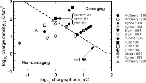
Damaging and non-damaging levels of electrical stimulation of non-human brain with planar macroelectrodes using k = 1.85 in the Shannon equation to delineate the boundary between damaging and non-damaging stimulation. Black and gray solid symbols = tissue damage; open symbols = no damage. Studies referenced (Gilman et al 1975, Pudenz et al 1975, Brown et al 1977, Yuen et al 1981, 1984, Agnew et al 1983, McCreery et al 1988, 1990).
The advantage of the Shannon equation for defining damaging levels of electrical stimulation relies on its simplicity. However, it is important to restate the range of stimulation conditions for which this model is applicable and to define areas where it cannot be readily used. Shannon outlined different scenarios for tissue damage as a function of distance from the electrode to the excitable tissue. The diagram in figure 2 represents these scenarios. The Shannon equation models histological data derived from near-field stimulation (figure 2(A)), which was postulated to give rise to the co-dependence on charge density and charge per phase identified by McCreery et al (1990). This codependence was postulated to arise from the non-uniform current distribution during a pulse, which results in higher current and charge densities at the perimeter of an electrode. For the disk electrodes used by McCreery et al (1990), equation (1) can be manipulated to show that the threshold current for tissue damage is linearly proportional to the circumference of the disk, consistent with tissue damage being caused by the nonuniform current distribution at the edge of the disk (Shannon 1992). At larger distances from the electrode, the mid-field and far-field cases (figures 2(B) and (C)), edge effects were considered negligible and in the far-field limit, the electrode appears to the target tissue as an electrical point source. The actual distance at which far-field behavior is observed is uncertain. Modeling studies for microelectrodes suggest that for distances greater than 50 μm, the electrode appears as a point source (McIntyre and Grill 2001). While a non-uniform current distribution may not directly cause neuronal damage at far-field distances from the electrode, this does not preclude damage by diffusion of noxious reaction products produced at the electrode by the high current densities associated with the non-uniform distribution.
Figure 2.
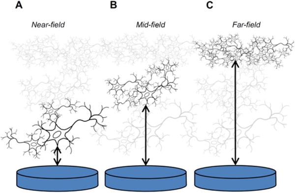
The three scenarios outlined by Shannon for electrode–tissue interaction as a function of distance between a disk electrode and excitable tissue, relative to the electrode diameter. In the near-field case (A), non-uniform current density at the electrode circumference is postulated to contribute to tissue damage; in the mid-field case (B) the current density is lower and more uniform; and, in the far-field case (C) the electrode acts as a point source in which the current uniformity and density at the electrode are not factors affecting tissue damage.
Stimulation parameter space not covered by the Shannon equation
As noted by Shannon, equation (1) contains information on the pulse width, current, and electrode area, but these parameters are not explicitly represented in figure 1 and, for a particular electrode area, a range of stimulation conditions at different current densities and pulse widths are represented by a single point. This situation can obscure important differences between waveforms. For example, Butterwick et al (2007) demonstrated the importance of current density in determining the occurrence of irreversible damage of retinal cells and showed that the threshold current density for damage varies significantly with both pulse width and pulse frequency. They also showed that macroelectrode and microelectrode current thresholds scaled differently with electrode area, exhibiting a macro- to-microelectrode boundary between 200 μm and 300 μm diameter (3 × 10⁻⁴ cm2 and 7 × 10⁻⁴ cm2). The effects of pulse frequency are also not captured in figure 1 and McCreery et al (1995, 1997) have shown the importance of frequency as a factor in determining the extent of damage to peripheral nerve, in the form of early axonal degeneration, and to the persistent depression of neuronal excitability following stimulation of the cortex. In the latter case, stimulation-induced depression of neuronal excitability (SIDNE) may persist for several days following cessation of the stimulation, although it was not associated with observed histological changes. Lower frequency stimulation invariably resulted in reduced nerve damage and reduced SIDNE. Whether longer periods of pulsing at stimulation intensities that induce SIDNE will also induce observable neural damage is not known. A particularly relevant parameter for many clinical stimulation devices, also not captured in figure 1, is duty cycle (i.e the percentage of time the stimulation pulse train is applied). Duty cycle can vary from a few percent for responsive or scheduled stimulation paradigms to approaching 100% in DBS for movement disorders. Although stimulus frequencies for clinical DBS (130–185 Hz) are higher those used in most studies of stimulation-induced neural damage, minimal adverse tissue response has been reported (Haberler et al 2000, Burbaud et al 2002). As suggested by Kuncel and Grill (2004), the absence of clinically relevant tissue damage observed in post-mortem studies of DBS patients is likely due to the low charge densities employed clinically. Based on an assumed electrode resistance of 1100 Ω, we estimate a maximum charge/phase and charge density of 0.5 μC and 8 μC cm−2 from the data of Burbaud et al (2002) and Haberler et al (2000).
Another point to consider is that histopathological outcomes may not have sufficient resolution to identify changes induced at the nerve or neuronal level by the presence of the implant, as well as by stimulation (for example, SIDNE). In the peripheral nervous system, nerve conduction studies and other measures may provide supplemental information to histological assays in order to assess changes in function, although limitations of these measurements must be considered. For implants in the brain, an additional concern is induced hyperexcitability of neurons, which may not be easy to identify using standard histological measures. Hyperexcitability induced by trauma such as brain injury can lead to excess neurotransmitter release in the surrounding tissue and subsequent neurotoxicity (McNamara et al 2006). This can cause a progression eventually leading to circuit disruption or dysfunction, such as epileptogenesis. Given the sometimes slow time-course of the progression, low prevalence, and the difficulty in identifying the underlying mechanistic causes, full investigation of these safety concerns may require monitoring during both non-clinical and clinical investigations.
Clinical stimulation levels reported in literature
While it is clear that the representation of a tissue damage threshold based on equation (1) and figure 1 does not capture all the important parameters of a stimulation protocol, many clinical neural stimulation devices respect this threshold at a k-value between about 1.5 and 1.8. Several examples based on clinical stimulation levels reported in published literature or manufacturer labeling information for vagus nerve, deep brain structures, and cortical surface electrodes are shown in figure 3. While some clinical devices are capable of delivering stimulus pulses above the Shannon limit, this practice is usually accompanied by a warning.
Figure 3.
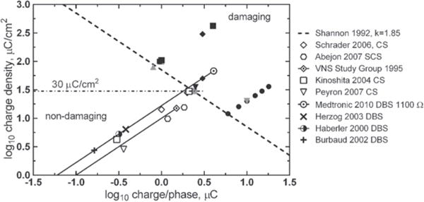
Levels of neural stimulation for clinical devices in humans as reported in published literature or manufacturer device labeling. Vagus Nerve Stimulation (VNS) data from Cyberonics (The Vagus Nerve Stimulation Study Group 1995) assumes a GSA = 0.1 cm2, which was estimated from Terry et al (1990) and Bullara (1990) for a 2 mm inside diameter helix. SCS—spinal cord stimulation, CS—cortical surface stimulation, DBS—deep brain stimulation. DBS charge values are calculated from stimulation voltage levels using an impedance of 1100 Ω. The solid lines for the VNS Study Group and Medtronic DBS data reflect the wide range of possible stimulation intensities available with these treatments. Filled symbols are damaging stimulation levels from figure 1. Studies referenced (Shannon 1992, Haberler et al 2000, Burbaud et al 2002, Herzog et al 2003, Kinoshita et al 2004, Schrader et al 2006, Abejon and Feler 2007, Peyron et al 2007, Medtronic 2010).
The range of electrode areas for the clinical studies shown in figure 3 is about 0.06–0.12 cm2. Cochlear prostheses and emerging clinical applications such as auditory brain stem stimulation for hearing and retinal stimulation for vision employ smaller electrodes with surface areas that are generally less than 0.01 cm2. Typical clinical levels or sensory thresholds for these smaller electrodes are compared with larger electrodes in figure 4. Although there are no tissue damage data specific to the use of the smaller electrodes in the sensory prostheses, the clinical stimulation levels as reported in published literature remain mostly within the Shannon limit for k = 1.85.
Figure 4.
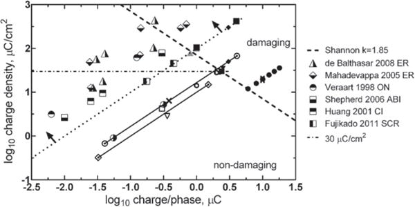
Levels of neural stimulation for clinical devices with electrodes having a GSA < 0.01 cm2 (region above and to the left of the dotted line as indicated by the arrows). See figures 1 and 3 for symbols not in the legend. Stimulation targets: ER—epi-retinal surface, ON—optic nerve surface, ABI—auditory brain stem surface, CI—cochlear implant, SCR- suprachoroidal placement targeting the retina. Studies referenced (Shannon 1992, Veraart et al 1998, Huang et al 2001, Mahadevappa et al 2005, McCreery and Shepherd 2006, Balthasar et al 2008, Fujikado et al 2011).
Origin of the 30 μC cm−2 damage threshold
The first deep brain stimulator approved in the US, the Medtronic Activa Tremor Control System (US FDA 1997) for essential tremor, was approved with a maximum charge density of 30 μC cm−2 (Kuncel and Grill 2004, Medtronic 2010a, 2010b). This limit was based on damage thresholds in animal studies reported by McCreery et al (1990). As discussed by Kuncel and Grill (2004), such a limit can also be obtained by extending the charge density/charge per phase line for a typical macroelectrode GSA (0.06 cm2 in the case of Medtronic DBS electrodes, in their example) to the Shannon line for k ≈ 1.75. Likewise, for cochlear implants, histological observations from early studies with cochlear stimulation also suggested that 30 μC cm−2 was non-damaging (Shepherd et al 1983a, 1983b) and device sponsors have proposed this as an upper limit for use in cochlear prosthesis patients (Clark 2006). Spinal cord stimulation for chronic pain is an exception. These electrodes, which are placed in the extradural space and are thus separated from the neural fibers by the dura and cerebrospinal fluid, are currently approved for stimulation at charge densities significantly higher than 30 μC cm−2 based on nonclinical safety studies.
However, damaging stimulation protocols with charge densities as low as 12 μC cm−2 were reported in McCreery’s original study (McCreery et al 1990), with damage thought to be caused by a high charge per phase (6 μC/phase) even though the k value for this stimulus intensity is only 1.4. This work emphasizes the importance of both charge density and charge per phase when stimulating with large-area electrodes. In addition, more recent reports suggest that charge densities up to 60 μC cm−2 (k ~ 1.25 for a 0.005 cm2 electrode) may be non-damaging when used in cochlear prostheses (McCreery and Shepherd 2006). From these examples, it should be evident that charge density alone is not sufficient to predict stimulation damage. It is possible to stimulate below 30 μC cm−2 and generate tissue damage; conversely, it is possible to stimulate up above that level and not produce tissue damage that results in a decline in functional performance.
Microelectrode stimulation
As the distance between the electrode and target tissue increases, the electrode progressively behaves as a current point source with respect to the tissue target. This is the far-field condition described by Shannon (1992). Simulation and experimental data suggest that this distance is about 2–5 times the largest exposed electrode dimension (Suesserman and Spelman 1993, McIntyre and Grill 2001). In the far-field condition, the neuronal population activated by electrical stimulation is not a function of the electrode area or geometry. For typical microelectrodes with a GSA range of 200–2000 μm2, point source behavior is observed for distances greater than about 50 μm form the electrodes (Carter et al 1995, McIntyre and Grill 2001). Provided that the charge and current densities at the electrode are low enough to avoid generating noxious chemical byproducts or inducing electroporation during stimulation, the GSA and shape of the electrode should not be significant factors determining tissue damage thresholds. Based on the results of modeling studies by McIntyre and Grill (2001) and further supported by experimental studies by McCreery et al (1992, 1997) indicating that depression of neuronal excitability was strongly correlated with charge per phase but not charge density in their study of penetrating microelectrode, the geometric area and shape of the electrode should not be significant factors determining tissue damage thresholds provided that the charge and current densities at the electrode are low enough to avoid generating noxious chemical byproducts or inducing electroporation during stimulation. Damaging and non-damaging levels of microelectrode stimulation employed in various animal and human studies are shown in figure 5. It is clear from the microelectrode data that damaging stimulation levels fall well-below the threshold predicted using a Shannon line with k = 1.85 and charge densities are well-above 30 μC cm−2. Emerging from these data is a 4 nC/ph tissue damage threshold, which is indicated in figure 5 by the vertical dashed line (McCreery et al 1994, 2010). It is evident that the charge density and charge per phase relationship defined by the Shannon equation for macroelectrodes does not apply directly to microelectrodes. Based on the suggested mass action mechanism for tissue damage (Agnew et al 1990, 1993, McCreery et al 1994), microelectrodes should have a charge per phase threshold for tissue damage. Analogous to the Shannon line, it is important to avoid assigning too much significance to the 4 nC/phase threshold shown in figure 5. Damaging levels of charge/phase with microelectrodes will also depend on pulse frequency and duty cycle of the stimulation. Furthermore, the threshold and physical manifestation of damage can depend on the type of stimulated neural tissue (McCreery et al 1994). Such damage would be expected to occur at some distance from the microelectrode without any noxious reactions occurring at the electrode–tissue interface during charge injection. However, if intact cells are close enough to the microelectrode, there is the possibility of cell damage by electroporation and this damage will depend on the current density and pulse width (Butterwick et al 2007).
Figure 5.
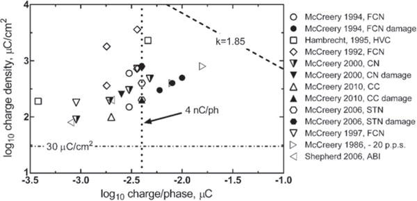
Levels of neural stimulation in animal and human studies involving penetrating microelectrodes (geometric area < 2000 μm2) showing an approximate damage threshold of 4 nC/ph. Filled symbols indicate histological damage; open symbols no damage; partially filled symbols damage but compromised physiological response. The data point (▷), for which no histological damage was observed, employed a pulse frequency of 20 Hz compared with 50 Hz or greater for the other studies. FCN—feline cochlear nucleus, HVC—human visual cortex, CC—cerebral cortex, STN—subthalamic nucleus, ABI—auditory brain stem. Studies referenced (Hambrecht 1995, McCreery et al 2006, 2010, 1986, 1992, 1994, 1997, 2000, McCreery and Shepherd 2006).
Electrochemical versus geometric surface area
The need to increase charge injection capacity for microelectrode stimulation and the desire, particularly in cardiac pacing (Schaldach et al 1990, Bolz et al 1993), to reduce electrode polarization during pulsing led to the investigation of roughened or porous electrodes with an enhance electrochemical surface area. Increasing the available electrochemical surface area for charge injection increases the charge that can be injected without inducing potentially harmful reactions such as electrode dissolution or water electrolysis (Huang and Shepherd 2000). However, for the practical reason that the electrochemical surface area is difficult to measure and depends on the measurement technique, the geometric surface area of an electrode is typically used to determine charge density. All the data used in the construction of figures 1 and 3–5 employed the geometric surface area. An additional difficulty with using an electrochemical surface area, particularly for a porous electrode, is that the surface area available to support charge injection depends on both the magnitude of the imposed current and pulse width. This is due to the effect of pore resistance and the associated time constant for accessing the electrode surface area within the pore structure (DeRosa et al 1973, Cogan 2008). While increasing electrochemical surface area will result in some increase in the reversible charge-injection capacity of an electrode calculated with the geometric surface area, the charge per phase experienced by the tissue will remain unchanged. For microelectrode stimulation, therefore, in which the charge per phase is the likely determinant of tissue damage at far-field distances, differences in electrochemical surface area should not affect tissue damage thresholds. Even for a damaging process such as electroporation, which occurs close to the electrode and is related to current density in the tissue, adjacent cells will be at least a few microns from the electrode surface and current and charge densities are better described in terms of the electrode geometric surface area.
Electrode material
In clinical neural stimulation devices employing macroelectrodes the electrode material is almost exclusively platinumbased (Merrill et al 2005, Cogan 2008). The McCreery studies (McCreery et al 1990) which formed the basis of the Shannon equation where made with platinum electrodes and differences in charge-injection mechanisms and charge-injection limits for different electrode materials are not represented by the Shannon equation. Like tissue damage thresholds, the maximum charge injection capacity of an electrode depends on the details of the pulsing protocol and also raises the question of what differences there may be between electrode limits established in saline electrolytes and those encountered in vivo. Charge can be injected either capacitively, via charging of the electrode double-layer, or faradaicly, by electron transfer through reduction and oxidation reactions occurring at the electrode surface. The relative contribution of the capacitive and faradaic processes, as well as nature of electrochemical reactions, is a function of the electrode material (Cogan 2008). The maximum injectable charge from an electrode is usually defined as the charge density that polarizes the electrode to the onset of water reduction or oxidation, which itself is a function of electrode area and of several inter-related waveform parameters including pulse width, current density, inter-pulse potential, and, if employed, inter-pulse bias. Possible consequences of exceeding water electrolysis potentials are large pH excursions, formation of gas bubbles, and delamination or dissolution of electrode coatings (Huang et al 2001, Cogan et al 2004). However, the evidence to date with typical electrode materials, such as platinum or iridium oxide, suggests that neural hyperactivity rather than irreversible electrode processes is the first damage mechanism encountered as the intensity and frequency of stimulation are increased (Agnew and McCreery 1990, Agnew et al 1990, 1993, McCreery et al 1994). This conclusion is based on the observation that charge densities associated with tissue damaging levels of stimulation are lower than accepted maximum electrode charge densities for avoiding water electrolysis. This does not preclude reactions which may occur during a stimulation pulse, such as metal dissolution, oxygen reduction, and pH changes, from causing tissue damage or initiating a tissue damaging cascade even though the overall pulse protocol does not induce damage by hyperactivity. These electrochemical reactions, therefore, should not be excluded as tissue damaging processes even though the charge density may be within reported reversible limits. This is particularly so, because recent reports suggest that the in vivo electrochemical limits of charge injection, as defined by the charge density that avoids electrochemical potentials at which water electrolysis occurs, are significantly lower than those measured in saline electrolytes (Hu et al 2006, Kane et al 2013, Terasawa et al 2013, Leung et al 2015). The apparent in vivo charge injection capacity may be as much as a factor of 10 lower for platinum and activated iridium oxide (AIROF), and a factor of four lower with SIROF microelectrodes. Observations from in vivo studies using activated iridium oxide (AIROF) microelectrodes also demonstrated that physical electrode damage is possible when these electrodes are pulsed to potentials more negative than that for reduction of water (approximately −0.6 V versus Ag|AgCl) (Cogan et al 2004, Hu et al 2006). While the in vivo response of other electrode materials is uncertain, it is obviously prudent to avoid polarization to potentials at which water electrolysis occurs and, if such excursions cannot be avoided, the in vivo stability of the electrode and the possibility of tissue damage should be carefully evaluated. An interesting consideration in the in vivo evaluation of charge injection limits is the effect of tissue capacitance on the voltage waveform measured during constant current pulsing. Modeling studies suggest that the impact of tissue capacitance can be significant at short pulse widths and high current amplitudes and those in vivo measurements of charge injection capacity at pulse widths shorter than about 200 μs may be affected by tissue capacitance (Butson and McIntyre 2005).
In vivo measurements aside, the maximum charge-injection capacity of platinum in physiological saline that avoids potentials at which electrolysis of water can occur (Merrill et al 2005, Cogan 2008) varies with the pulse waveform and surface roughness, but it is on the order of 35–100 μC cm−2 for smooth platinum and as high as 1 mC cm−2 for some porous platinum electrodes (Rose and Robblee 1990, Terasawa et al 2013, Leung et al 2015). Emerging neural prostheses may also employ porous titanium nitride or iridium oxide electrodes (Weiland et al 2002, Mathieson et al 2012). Approximate charge-injection capacities of Pt-based electrodes, TiN and iridium oxide are shown in figure 6 on a damage threshold plot and include data for sputtered iridium oxide (SIROF) and porous platinum obtained from in vivo studies. As cautioned above, the charge injection capacity of the SIROF electrodes, chronically implanted for over 300 days in cat cortex, were decreased by a factor of two to four (Kane et al 2013). The porous platinum electrodes suffered a factor of eight reduction in charge capacity after being implanted for ~45 days in rabbit sclera (Terasawa et al 2013). The plot in figure 6 includes the macroelectrode stimulation data from figures 1, 3 and 4 and the microelectrode data from figure 5. The electrode limits for avoiding electrolysis of water are shown as horizontal lines; dependent on charge density only and not charge per phase. The charge-injection capacity of an electrode is however inversely dependent on electrode area (Cogan et al 2009). The prospects for other electrode materials, such as polyethylenedioxythiophene (Cui and Zhou 2007, Luo et al 2011), carbon nanotubes (Wang et al 2006), and conductive diamond (Hadjinicolaou et al 2012), in devices for human use are still uncertain, pending more detailed data on their chronic biocompatibility, stability, and an in vivo assessment of their charge-injection capacity. What is evident from figure 6 and the discussion above is that macroelectrode charge density limits are generally well-above charge densities employed clinically such as with deep brain and vagus nerve stimulation. In the case of microelectrodes, the situation is less clear and additional studies are necessary to determine electrode charge injection limits in view of the dramatically decreased in vivo values and the question of how voltage transients are measured and interpreted.
Figure 6.
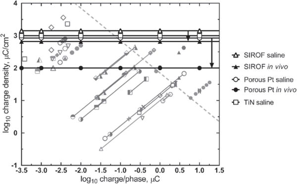
Reversible electrochemical limits of charge injection for SIROF (Cogan et al 2009, Kane et al 2013), porous platinum (Terasawa et al 2013) and titanium nitride (Weiland et al 2002) electrodes overlying functional and tissue damage thresholds for micro and macroelectrodes. The difference between saline and in vivo measurements of maximum charge injection capacity are shown for SIROF and porous platinum and the range indicated by arrows. See figures 1 and 3–5 for an explanation of the shaded symbols.
Stimulation waveforms
The charge density and charge per phase values used in the tissue and electrode damage threshold plots from figures 1, 3–6, are derived from the leading phase of a nominally charge-balanced biphasic pulse. There are a variety of strategies for achieving charge balance including the use of biphasic symmetric or asymmetric current pulses, shorting the stimulated electrode to a large-area return, shorting the active electrodes used to deliver a multi-polar pulse, active control of the interpulse potential, or some combination of these. None of this is captured in the damage threshold plots. It is unclear to what extent differences in waveforms will affect tissue damage and they are presumed to be secondary to hyperactivity driven neuronal damage unless the waveform is sufficiently unbalanced that a large shift in the interpulse potential results (Merrill et al 2005). In most clinical devices, the stimulator output is capacitor-coupled to prevent a net dc current, although these capacitors usually have some dc leakage (Huang et al 1999). These leakage currents are designed to be small and are probably inconsequential for macroelectrodes, but this may not be the case with microelectrodes, particularly if the GSA is very small (<500 μm2). It is worth noting that stimulation protocols that control the electrode potential in the inter-pulse period cannot employ a dc isolation capacitor. A net dc current is also necessary to maintain the electrode at a non-equilibrium potential such as the anodic bias often employed with activated iridium oxide electrodes (Beebe and Rose 1988). Tissue damage studies with AIROF electrodes have not shown any deleterious effect of the bias on unpulsed but biased controls, or biased electrodes pulsed at modest intensities (≤3.6 nC/ph) (McCreery et al 1992, 2010). However, some net current flow, albeit small, is necessary to maintain a non-equilibrium value.
Non-uniform current distribution
The current distribution across a stimulation electrode is to varying degrees non-uniform and this effect has been modeled (Rubinstein et al 1987, McIntyre and Grill 2001), demonstrated in saline (Suesserman et al 1991, Wang et al 2014), and recently demonstrated in in vitro preparations of neural cells (Ghazavi et al 2013). By manipulating the current distribution through electrode geometry, reduced electrode impedance, lower threshold power and lower voltage for neural excitation can be achieved (Grill and Wei 2009, Ghazavi et al 2013). However, measurements in saline of electrodes designed to promote lower overall impedance by manipulating the current distribution, while successful, have demonstrated only modest benefit (Grill and Wei 2009, Wei et al 2009). One reason why modeling studies can overestimate the degree of current non-uniformity during stimulation is the change in spatial distribution of the current across the surface of the electrode during the course of a pulse. At the onset of a pulse, the current distribution across the electrode surface is determined solely by the electrode geometry and ionic resistivity of the electrolyte. This initial current distribution, the primary distribution, is characterized by large spatial non-uniformities with currents approaching infinity at the perimeter of non-recessed disk electrodes (Rubinstein et al 1987). However, as the pulse proceeds, reaction kinetics, in the form of activation overpotentials, act to moderate the non-uniformity leading to a secondary current distribution that is more uniform than the primary distribution (Wang et al 2014). The importance of the secondary current distribution becomes more pronounced at higher current densities and longer pulse widths that allow more time for activation overpotentials to develop. This effect is seen in the study by Susserman et al (1991) who showed the increasing uniformity in current distribution across non-recessed disk electrodes as the frequency of a sinusoidal driving current was decreased below about 3 kHz. In addition, if the transport of reactants to the electrode begins to limit charge injection, concentration overpotentials become significant and the non-uniformity in the current distribution is further reduced (tertiary distribution). When the electrode–electrolyte interface is incorporated into modeling studies, significantly more uniform distributions are obtained. Cantrell et al (2008) used an equivalent circuit model of the platinum–electrolyte interface comprised of a voltage-dependent constant phase element and charge transfer resistance in their finite element modeling studies of microelectrodes. They demonstrated highly uniform current profiles at the tips of conical electrodes at current densities similar to those employed in neural stimulation. Their modeling suggests however that current distribution is much less uniform if the electrode is polarized into the nonlinear charge transfer regime. In a similar manner, modeling studies by McIntyre and Grill (2001) showed that a reduction in the non-uniformity of the current distribution should be expected across microelectrodes that are coated with a thin modestly conducting film. The voltage drop across this film is analogous to the overpotentials generated by electrode reactions and consequently moderates non-uniformities in the current across the surface of the electrode.
It is also instructive to consider stimulation in the absence of an electrode–tissue interface. Charge-injection via a saline-filled pipette electrode, does not moderate the current non-uniformity. Since the electrode–tissue interface is absent, there are no reaction overpotentials and the primary current distribution is preserved throughout the pulse. Tissue damage observed by Butterwick et al (2007) in their study of stimulation-induced damage in explanted chick retina, using saline electrodes, reflects the non-uniformity of the primary current distribution. A similar effect was observed by Cohen et al (2011) in their optical coherence tomography study of stimulation-induced damage in rabbit retina, also with saline electrodes, which showed vividly the development of nonuniform retinal damage in real-time. Also, an ideally non-polarizable electrode should behave like a saline electrode and exhibit a non-uniform current distribution.
The extent to which non-uniform currents are a factor in tissue damage with clinical electrodes is less certain. Histological reports of stimulation-induced tissue damage from post-mortem human or animal studies have not revealed a geometric pattern of tissue damage that can be associated with a non-uniform current distribution. This however does not preclude non-uniform currents as a source of tissue damage or electrode corrosion, and preferential corrosion at the edge of platinum disk electrodes subjected to high charge density pulsing (240 μC cm−2) has been reported (Wang and Weiland 2012).
Regulatory considerations for safe stimulation
An implantable neuromodulation device has some inherent risk due to the implantation procedure and long-term physiological reaction to a system placed in the body. For example, a deep brain stimulator requires the temporary insertion of a guide cannula into the brain, and a long-term placement of an indwelling electrode in the deep brain. Known complications of the procedure include infection, hemorrhage, and stroke; however, the likely benefits to the patients have been determined to outweigh the risks through extensive non-clinical and clinical testing of medical devices for the indications approved by the FDA. However, the tissue damage risks are not as well understood for stimulation and hardware parameters outside of those for approved medical devices. Parameters such as electrode area, shape and material, pulse width, current amplitude, frequency, and duty cycle may all be relevant to tissue damage. In addition, there may be circumstances where it is necessary to exceed the limits placed on approved medical devices (for example, 30 μC cm−2 for deep brain stimulators) to obtain the desired clinical benefit. For microelectrodes, where physiological thresholds of about 1–2 nC/ph have been reported for ~1000 μm2 electrodes, this results in a threshold charge density of 100–200 μC cm−2 (McCreery 2008), which is greater than approved for DBS stimulation.
FDA regulations do not preclude stimulation at these higher levels; but as with any device the FDA places the onus on the investigator to conduct sufficient non-clinical and/or clinical testing to clearly define the benefits and risks to the patient (US FDA 2012). Early device safety testing may include bench and/or in vivo non-clinical testing to evaluate device performance in contexts that are as designed to shed light on future clinical use parameters. At certain points during device development, additional non-clinical testing may not provide the information needed to advance the developmental process. At these junctures, early feasibility or first-in-human clinical studies may be appropriate to obtain initial insights into factors including clinical and device safety (US FDA 2013c). The FDA’s Center for Devices and Radiological Health has recently identified increasing the number of early feasibility/first-in-human clinical trials conducted in the US as a Center priority (US FDA 2014c). In addition, a ‘staged’ approach to clinical trials, with enrollment of a limited number of patients in the early phase of a clinical study may be used to mitigate risk by limiting exposure of an investigational device to a smaller subject population (US FDA 2014b).
The FDA determination of safety is based on performance data specific to a given device and medical indication. This allows devices sponsors to propose test protocols which are most appropriate and effective for the device in question. However, to provide predictability to the review process, the FDA does publish guidance documents and recognizes common standards to provide investigators with accepted non-clinical tests that define safety parameters (US FDA 2014d, 2014e). For instance, the FDA recognizes AAMI/ANSI/ISO 14708-3 2008-01-01, Implants for surgery —Active implantable medical devices–Part 3: Implantable neurostimulators, which describes bench testing protocols for implanted neurostimulator devices. Currently, there is no published guidance document or recognized standard that deals explicitly with stimulation safety of macro- and microelectrodes over a range of stimulation parameters. Due to the lack of established stimulation safety standards, and to the wide range of technological specifications and proposed clinical indications for neuromodulation devices, specific testing protocols can vary across device types and device sponsors/manufacturers.
When considering novel strategies to improve the safety of neuromodulation devices, the FDA advises sponsors to contact that agency early in the process to introduce the new technology and obtain feedback. Such interactions typically fall under the FDA’s Pre-Submission program (an expansion of the previous pre-IDE program). Of note in the relevant guidance is that the FDA encourages sponsors to use a Pre-Submission when they ‘desire FDA guidance on specific issues related to nonclinical study protocols and/or animal study protocols, before initiating your studies’ (US FDA 2014f). This mechanism allows the sponsor to obtain feedback on expensive and time-consuming pre-clinical studies before they are initiated. Although advice in these Pre-Submission interactions is non-binding, ‘the FDA intends to provide the best possible advice in accordance with the information provided, ensure it is captured accurately in the meeting minutes drafted by the sponsor, and commit to that advice unless the circumstances sufficiently change such that our advice is no longer applicable, such as when a sponsor changes the intended use of their device after we provide feedback’. Early interactions between the FDA and device sponsors can maximize the efficiency of the collection of data for bench, preclinical and/or clinical data needed to support a marketing submission.
Possible future studies
It is evident that our knowledge of how the electrode material, electrode geometry, and stimulation waveform affects tissue damage is incomplete. We have also limited knowledge of how tissue damage compromises physiological function and to what extent tissue damage might be tolerated. Some areas of study that might clarify the role of the various electrode and stimulation parameters in relation to stimulation-induced tissue damage are briefly identified. This is not a complete list and it will be appreciated that there is interdependency between the studies identified.
Tissue effects on charge-injection limits
As discussed, in vivo measurements of electrode charge-injection capacity based on avoiding potentials that electrolyze water are considerably lower than those measured in buffered saline. This phenomenon seems to apply to all types of electrode material and arises at least in part from the treatment of tissue as a resistive rather than reactive circuit element (Butson and McIntyre 2005). A more detailed study, both in vivo and by modeling, might establish the relationship between saline charge-injection capacities and the maximum charge that can be injected in vivo without inducing harmful electrochemical reactions or irreversibility.
Electrode surface morphology
Measurements in saline show that increasing the electrochemical surface area for a fixed geometric surface area results in reduced polarization during pulsing and reduced impedance. Using high real-surface-area Pt electrodes (HiQ electrodes), Tykocinski et al 2001 showed that the initial benefit of reduced polarization was quickly lost due to fibrous encapsulation. After 55–201 days implantation in cat scala tympani the polarization of HiQ electrodes was not statistically different from standard Pt electrodes in response to biphasic current pulsing. In vitro and also early in vivo measurements, therefore, may not reflect the chronic performance of roughened or microporous electrodes. Results from studies with similar objectives would inform our understanding of the long-term performance benefits for stimulating electrodes from increased electrical surface area. Exploration of roughened Pt and other electrode coatings, including TiN and iridium oxide, placed in other types of neural tissue, would help to elucidate any advantage of increased surface morphology, particularly for chronic preparations.
Faradaic versus capacitive charge injection
In a single study, McCreery et al (1988) showed that under equivalent stimulation conditions, Ta/Ta2O5 electrodes operating by capacitive charge-injection were as equally damaging to tissue as platinum electrodes, which inject charge at least partially by faradaic mechanisms. This study supports the assertion that neural hyperactivity rather than the generation of noxious products at an electrode is the first tissue damage mechanism encountered as simulation intensity is increased. Repeating this study with indwelling as well as surface electrodes and including contemporary capacitive and faradaic electrodes such as fractal-TiN and sputtered iridium oxide (Weiland et al 2002, Cogan et al 2009) would usefully confirm the earlier findings. It would also be informative to investigate whether charge density regimes can be identified in which there are differences in the extent and type of stimulation-induced tissue damage between capacitor and faradaic electrodes.
Platinum dissolution
Platinum and PtIr-alloys will likely remain the material of choice for stimulation applications that do not employ microelectrodes. Early studies demonstrated that Pt dissolution is greatly reduced in the presence of proteins that retard corrosion by adsorbing on to the electrode surface and restricting reactant and product transport (Robblee et al 1980), although some Pt dissolution persists (Hibbert et al 2000). It would be valuable to investigate platinum dissolution in vivo and to determine the effects of biomolecule adsorption and tissue encapsulation on the dissolution process and the evolution of harmful electrochemical species. It would be particularly useful to investigate the correlation between stimulation intensity, metal dissolution, and stimulation-induced tissue damage in chronic studies using charge density levels that include and challenge currently accepted thresholds.
Tissue damage assessment
Improved methods of observing the mechanisms of induced changes in the biology—including SIDNE, electroporation, hyperexcitability—acutely and chronically in vivo, are required so we can iterate through stimulation and electrode design parameters quickly and monitor the biological effects, preferably in real time. Emerging tools employing optical reporters and multi-photon microscopy (e.g. Kozai and Vazquez 2015) have some promise for in vivo and in vitro preparations. At the very least, we should apply the full armamentarium of histological techniques available.
Tissue damage and functional performance
We need to understand the impact of stimulation-induced tissue damage in terms of the practical function of a chronic neuromodulation device. Does damage caused by stimulation increase or cause a functional deficit in the patient or otherwise impair the therapeutic benefit of the device? It would be useful to correlate the progression and severity of tissue damage in animal models having a quantifiable functional response to the stimulation. It might be revealing if specific electrode reactions, including dissolution, or specific neural damage mechanisms could be correlated with changes in physiological function.
Tissue damage in peripheral nerves
The majority of the studies discussed in this article address stimulation and tissue damage of the central nervous system. Similar studies have also been conducted in peripheral nerve (McCreery et al 1995, Agnew et al 1999). While these studies have elucidated damage mechanisms and provided guidance in selecting non-damaging stimulation waveforms, a detailed understanding of damage mechanisms and how the stimulus waveform, selection of electrode material, current distribution, the role of nerve regeneration, and so on, affect chronic functional performance has yet to be achieved. With increased interest in peripheral nerve stimulation, particularly the innervation of end organs in the viscera (Famm et al 2013) and the use of high-frequency stimulation for blocking nerve conduction (Patel and Butera 2015), a more complete understanding of damage mechanisms in small and large peripheral nerves is highly desirable.
Conclusions
We have attempted to summarize what is published regarding stimulation-induced damage of neural tissue and, at least qualitatively, to describe how major elements of a stimulation protocol, including choice of electrode material, are expected to affect tissue damage thresholds. There is considerable uncertainty in predicting electrical thresholds for tissue damage and the commonly used Shannon equation may be a helpful guide for macroelectrode stimulation. However, the Shannon equation is modeled on data obtained with a limited set of stimulation parameters and under various circumstances, such as variations of pulse width, current density or stimulation duty cycle, the Shannon equation could under or overestimate a damage threshold. The extent to which the Shannon equation can apply to microelectrodes is unclear. When a microelectrode approximates a point source with respect to distant neurons, charge density is unlikely to be a direct determinant of neuronal damage. Damage severity and mechanisms are dependent on device physical characteristics, tissue proximity and stimulation mechanisms of action. Correspondingly, preclinical testing to demonstrate performance and reliability may also be device-specific. However, early interactions with FDA regulatory staff can ensure that proposed testing will provide data in support of device safety. The key points are summarized as follows:
Besides charge density and charge per phase, other factors including pulse frequency, duty cycle, and current density may profoundly influence tissue damage;
Decreasing the pulse frequency and employing intermittent, low duty cycle pulsing greatly reduces tissue damage or depression of neuronal excitability;
Macroelectrodes and microelectrodes have different tissue damage thresholds, and microelectrode charge densities above 30 μC cm−2 may be required in emerging devices;
Charge densities for assessing tissue damage are appropriately calculated using the geometric rather than electrochemical surface area of an electrode;
Non-uniform current distributions are moderated by electrode reactions but cannot be excluded as causes of tissue damage or electrode corrosion;
With emerging microelectrode or macroelectrode applications employing charge densities >30 μC cm−2, appropriate non-clinical and/or clinical data are needed to support the safety of these stimulation levels.
Suggestions for future work that might help elucidate the mechanisms of tissue damage and inform the development of safer electrode designs and stimulation protocols have been made.
Acknowledgments
The authors would like to thank Dr Victor Krauthamer and Dr Leonardo Angelone (Office of Science and Engineering Laboratories), Dr Kristen Bowsher and Dr John R Doucet (Office of Device Evaluation) at Canter for Devices and Radiological Health, US Food and Drug Administration for reading and providing critical input to the manuscript.
References
- Abejon D, Feler CA. Is impedance a parameter to be taken into account in spinal cord stimulation? Pain Physician. 2007;10:533–40. [PubMed] [Google Scholar]
- Agnew WF, McCreery DB. Considerations for safety with chronically implanted nerve electrodes. Epilepsia. 1990;31:S27–32. doi: 10.1111/j.1528-1157.1990.tb05845.x. [DOI] [PubMed] [Google Scholar]
- Agnew WF, McCreery DB, Yuen TG, Bullara LA. MK-801 protects against neuronal injury induced by electrical stimulation. Neuroscience. 1993;52:45–53. doi: 10.1016/0306-4522(93)90180-n. [DOI] [PubMed] [Google Scholar]
- Agnew WF, McCreery DB, Yuen TG, Bullara LA. Evolution and resolution of stimulation-induced axonal injury in peripheral nerve. Muscle Nerve. 1999;22:1393–402. doi: 10.1002/(sici)1097-4598(199910)22:10<1393::aid-mus9>3.0.co;2-e. [DOI] [PubMed] [Google Scholar]
- Agnew WF, McCreery DB, Yuen TGH, Bullara LA. Local anaesthetic block protects against electrically-induced damage in peripheral nerve. J Biomed Eng. 1990;12:301–8. doi: 10.1016/0141-5425(90)90004-7. [DOI] [PubMed] [Google Scholar]
- Agnew WF, Yuen TGH, McCreery DB. Morphologic changes after prolonged electrical stimulation of the cat’s cortex at defined charge densities. Exp Neurol. 1983;79:397–411. doi: 10.1016/0014-4886(83)90221-2. [DOI] [PubMed] [Google Scholar]
- Bakris GL, Nadim MK, Haller H, Lovett EG, Schafer JE, Bisognano JD. Baroreflex activation therapy provides durable benefit in patients with resistant hypertension: results of long-term follow-up in the rheos pivotal trial. J Am Soc Hypertension. 2012;6:152–8. doi: 10.1016/j.jash.2012.01.003. [DOI] [PubMed] [Google Scholar]
- Balthasar CD, et al. Factors affecting perceptual thresholds in epiretinal prostheses. IOVS. 2008;49:2303–14. doi: 10.1167/iovs.07-0696. [DOI] [PMC free article] [PubMed] [Google Scholar]
- Beebe X, Rose TL. Charge injection limits of activated iridium oxide electrodes with 0.2 ms pulses in bicarbonate buffered saline (neurological stimulation application) IEEE Trans Biomed Eng. 1988;35:494–5. doi: 10.1109/10.2122. [DOI] [PubMed] [Google Scholar]
- Bolz A, Hubmann M, Hardt R, Riedmüller J, Schaldach M. Low polarization pacing lead for detecting the ventricular-evoked response. Med Prog Technol. 1993;19:129–37. [PubMed] [Google Scholar]
- Brown WJ, Babb TL, Soper HV, Lieb JP, Ottino CA, Crandall PH. Tissue reactions to long-term electrical stimulation of the cerebellum in monkeys. J Neurosurgery. 1977;47:366–79. doi: 10.3171/jns.1977.47.3.0366. [DOI] [PubMed] [Google Scholar]
- Bullara LA. Bidirectional helical electrode for nerve stimulation. US Patent. 1990;4:920–979. [Google Scholar]
- Burbaud P, Vital A, Rougier A, Bouillot S, Guehl D, Cuny E, Ferrer X, Lagueny A, Bioulac B. Minimal tissue damage after stimulation of the motor thalamus in a case of chorea-acanthocytosis. Neurology. 2002;59:1982–4. doi: 10.1212/01.wnl.0000038389.30437.1e. [DOI] [PubMed] [Google Scholar]
- Butson CR, McIntyre CC. Tissue and electrode capacitance reduce neural activation volumes during deep brain stimulation. Clin Neurophysiol. 2005;116:2490–500. doi: 10.1016/j.clinph.2005.06.023. [DOI] [PMC free article] [PubMed] [Google Scholar]
- Butterwick A, Vankov A, Huie P, Freyvert Y, Palanker D. Tissue damage by pulsed electrical stimulation. IEEE Trans Biomed Eng. 2007;54:2261–7. doi: 10.1109/tbme.2007.908310. [DOI] [PubMed] [Google Scholar]
- Cantrell DR, Inayat S, Taflove A, Ruoff RS, Troy JB. Incorporation of the electrode–electrolyte interface into finiteelement models of metal microelectrodes. J Neural Eng. 2008;5:54. doi: 10.1088/1741-2560/5/1/006. [DOI] [PubMed] [Google Scholar]
- Carter RR, McCreery DB, Woodford BJ, Bullara L, Agnew WF. Micturition control by microstimulation of the sacral spinal cord of the cat: acute studies. IEEE Trans Rehabil Eng. 1995;3:206–14. [Google Scholar]
- Clark GM. The multiple-channel cochlear implant: the interface between sound and the central nervous system for hearing, speech, and language in deaf people—a personal perspective. Phil Trans R Soc B. 2006;361:791–810. doi: 10.1098/rstb.2005.1782. [DOI] [PMC free article] [PubMed] [Google Scholar]
- Cogan SF. Neural stimulation and recording electrodes. Ann Rev Biomed Eng. 2008;10:275–309. doi: 10.1146/annurev.bioeng.10.061807.160518. [DOI] [PubMed] [Google Scholar]
- Cogan SF, Ehrlich J, Plante TD, Smirnov A, Shire DB, Gingerich M, Rizzo JF. Sputtered iridium oxide films for neural stimulation electrodes. J Biomed Mater Res B. 2009;89:353–61. doi: 10.1002/jbm.b.31223. [DOI] [PMC free article] [PubMed] [Google Scholar]
- Cogan SF, Guzelian AA, Agnew WF, Yuen TGH, McCreery DB. Over-pulsing degrades activated iridium oxide films used for intracortical neural stimulation. J Neurosci Methods. 2004;137:141–50. doi: 10.1016/j.jneumeth.2004.02.019. [DOI] [PubMed] [Google Scholar]
- Cogan SF, Troyk PR, Ehrlich J, Plante TD. In vitro comparison of the charge-injection limits of activated iridium oxide (AIROF) and platinum–iridium microelectrodes. IEEE Trans Biomed Eng. 2005;52:1612–4. doi: 10.1109/TBME.2005.851503. [DOI] [PubMed] [Google Scholar]
- Cohen E, Agrawal A, Connors M, Hansen B, Charkhkar H, Pfefer J. Optical coherence tomography imaging of retinal damage in real time under a stimulus electrode. J Neural Eng. 2011;8:056017. doi: 10.1088/1741-2560/8/5/056017. [DOI] [PubMed] [Google Scholar]
- Cui XT, Zhou DD. Poly (3,4-Ethylenedioxythiophene) for chronic neural stimulation. IEEE Trans Neural Syst Rehabil Eng. 2007;15:502–8. doi: 10.1109/TNSRE.2007.909811. [DOI] [PubMed] [Google Scholar]
- DeRosa JF, Beard RB, Carim HM, Dubin SE. Polarization and corrosion studies of porous and solid anodes for implantable power-generating electrodes. IEEE Trans Biomed Eng. 1973;BME-20:345–9. doi: 10.1109/TBME.1973.324286. [DOI] [PubMed] [Google Scholar]
- Famm K, Litt B, Tracey KJ, Boyden ES, Slaoui M. Drug discovery: a jump-start for electroceuticals. Nature. 2013;496:159–61. doi: 10.1038/496159a. [DOI] [PMC free article] [PubMed] [Google Scholar]
- Fujikado T, et al. Testing of semichronically implanted retinal prosthesis by suprachoroidal-transretinal stimulation in patients with Retinitis Pigmentosa. IOVS. 2011;52:4726–33. doi: 10.1167/iovs.10-6836. [DOI] [PubMed] [Google Scholar]
- Ghazavi A, Westwick D, Xu F, Wijdenes P, Syed N, Dalton C. Effect of planar microelectrode geometry on neuron, stimulation: finite element modeling and experimental validation of the electrode shape. J Neurosci Methods. 2015;248:51–8. doi: 10.1016/j.jneumeth.2015.03.024. [DOI] [PubMed] [Google Scholar]
- Gilman S, Dauth GW, Tennyson VM, Kremzner LT, Defendini R. Morphological and biochemical effects of chronic cerebellar stimulation in monkey. Trans Am Neurol Assoc. 1975;100:9–14. [PubMed] [Google Scholar]
- Grill WM, Wei XF. High efficiency electrodes for deep brain stimulation. Conf Proc IEEE Eng Med Biol Soc. 2009;2009:3298–301. doi: 10.1109/IEMBS.2009.5333774. [DOI] [PMC free article] [PubMed] [Google Scholar]
- Haberler C, Alesch F, Mazal PR, Pilz P, Jellinger K, Pinter MM, Hainfellner JA, Budka H. No tissue damage by chronic deep brain stimulation in Parkinson’s disease. Ann Neurol. 2000;48:372–6. [PubMed] [Google Scholar]
- Hadjinicolaou AE, et al. Electrical stimulation of retinal ganglion cells with diamond and the development of an all diamond retinal prosthesis. Biomaterials. 2012;33:5812–20. doi: 10.1016/j.biomaterials.2012.04.063. [DOI] [PubMed] [Google Scholar]
- Hambrecht FT. Visual prostheses based on direct interfaces with the visual system. Baillieres Clin Neurol. 1995;4:147–65. [PubMed] [Google Scholar]
- Herzog J, et al. Two-year follow-up of subthalamic deep brain stimulation in Parkinson’s disease. Mov Disord. 2003;18:1332–7. doi: 10.1002/mds.10518. [DOI] [PubMed] [Google Scholar]
- Hibbert DB, Weitzner K, Tabor B, Carter P. Mass changes and dissolution of platinum during electrical stimulation in artificial perilymph solution. Biomaterials. 2000;21:2177–82. doi: 10.1016/s0142-9612(00)00146-0. [DOI] [PubMed] [Google Scholar]
- Hu Z, Troyk PR, Brawn TP, Margoliash D, Cogan SF. In vitro and in vivo charge capacity of AIROF microelectrodes. Conf Proc IEEE Eng Med Biol Soc. 2006;2006:886–9. doi: 10.1109/IEMBS.2006.259869. [DOI] [PubMed] [Google Scholar]
- Huang CQ, Carter PM, Shepherd RK. Stimulus induced pH changes in cochlear implants: an in vitro and in vivo study. Ann Biomed Eng. 2001;29:791–802. doi: 10.1114/1.1397793. [DOI] [PubMed] [Google Scholar]
- Huang CQ, Shepherd RK. Reduction in excitability of the auditory nerve following electrical stimulation at high stimulus rates: V. Effects of electrode surface area. Hear Res. 2000;146:57–71. doi: 10.1016/s0378-5955(00)00100-3. [DOI] [PubMed] [Google Scholar]
- Huang CQ, Shepherd RK, Center PM, Seligman PM, Tabor B. Electrical stimulation of the auditory nerve: direct current measurement in vivo. IEEE Trans Biomed Eng. 1999;46:461–9. doi: 10.1109/10.752943. [DOI] [PubMed] [Google Scholar]
- Ikramuddin S, et al. Effect of reversible intermittent intra-abdominal vagal nerve blockade on morbid obesity: the recharge randomized clinical trial. JAMA. 2014;312:915–22. doi: 10.1001/jama.2014.10540. [DOI] [PubMed] [Google Scholar]
- Kane SR, Cogan SF, Ehrlich J, Plante TD, McCreery DB, Troyk PR. Electrical performance of penetrating microelectrodes chronically implanted in cat cortex. IEEE Trans Biomed Eng. 2013;60:2153–60. doi: 10.1109/TBME.2013.2248152. [DOI] [PMC free article] [PubMed] [Google Scholar]
- Kinoshita M, et al. Electric stimulation on human cortex suppresses fast cortical activity and epileptic spikes. Epilepsia. 2004;45:787–91. doi: 10.1111/j.0013-9580.2004.60203.x. [DOI] [PubMed] [Google Scholar]
- Kozai TD, Vazquez AL. Photoelectric artefact from optogenetics and imaging on microelectrodes and bioelectronics: new challenges and opportunities. J Mater Chem B. 2015;3:4965–78. doi: 10.1039/C5TB00108K. [DOI] [PMC free article] [PubMed] [Google Scholar]
- Kuncel AM, Grill WM. Selection of stimulus parameters for deep brain stimulation. Clin Neurophysiol. 2004;115:2431–41. doi: 10.1016/j.clinph.2004.05.031. [DOI] [PubMed] [Google Scholar]
- Leung R, Shivdasani MN, Nayagam DAX, Shepherd RK. In vivo and in vitro comparison of the charge injection capacity of platinum macro electrodes. IEEE Trans Biomed Eng. 2014;62:849–57. doi: 10.1109/TBME.2014.2366514. [DOI] [PubMed] [Google Scholar]
- Luo X, Weaver CL, Zhou DD, Greenberg R, Cui XT. Highly stable carbon nanotube doped poly(3,4-ethylenedioxythiophene) for chronic neural stimulation. Biomaterials. 2011;32:5551–7. doi: 10.1016/j.biomaterials.2011.04.051. [DOI] [PMC free article] [PubMed] [Google Scholar]
- Mahadevappa M, Weiland JD, Yanai D, Fine I, Greenberg RJ, Humayun MS. Perceptual thresholds and electrode impedance in three retinal prosthesis subjects. IEEE Trans Neural Syst Rehabil Eng. 2005;13:201–6. doi: 10.1109/TNSRE.2005.848687. [DOI] [PubMed] [Google Scholar]
- Mathieson K, et al. Photovoltaic retinal prosthesis with high pixel density. Nat Photonics. 2012;6:391–7. doi: 10.1038/nphoton.2012.104. [DOI] [PMC free article] [PubMed] [Google Scholar]
- McCreery D, Lossinsky A, Pikov V, Liu X. Microelectrode array for chronic deep-brain microstimulation and recording. IEEE Trans Biomed Eng. 2006;53:726–37. doi: 10.1109/TBME.2006.870215. [DOI] [PubMed] [Google Scholar]
- McCreery D, Pikov V, Troyk PR. Neuronal loss due to prolonged controlled-current stimulation with chronically implanted microelectrodes in the cat cerebral cortex. J Neural Eng. 2010;7:036005. doi: 10.1088/1741-2560/7/3/036005. [DOI] [PMC free article] [PubMed] [Google Scholar]
- McCreery DB. Cochlear nucleus auditory prostheses. Hear Res. 2008;242:64–73. doi: 10.1016/j.heares.2007.11.014. [DOI] [PubMed] [Google Scholar]
- McCreery DB, Agnew WF, Yuen TG, Bullara L. Charge density and charge per phase as cofactors in neural injury induced by electrical stimulation. IEEE Trans Biomed Eng. 1990;37:996–1001. doi: 10.1109/10.102812. [DOI] [PubMed] [Google Scholar]
- McCreery DB, Agnew WF, Yuen TG, Bullara LA. Comparison of neural damage induced by electrical stimulation with faradaic and capacitor electrodes. Ann Biomed Eng. 1988;16:463–81. doi: 10.1007/BF02368010. [DOI] [PubMed] [Google Scholar]
- McCreery DB, Agnew WF, Yuen TG, Bullara LA. Relationship between stimulus amplitude, stimulus frequency and neural damage during electrical stimulation of sciatic nerve of cat. Med Biol Eng Comput. 1995;33:426–9. doi: 10.1007/BF02510526. [DOI] [PubMed] [Google Scholar]
- McCreery DB, Bullara LA, Agnew WF. Neuronal activity evoked by chronically implanted intracortical microelectrodes. Exp Neurol. 1986;92:147–61. doi: 10.1016/0014-4886(86)90131-7. [DOI] [PubMed] [Google Scholar]
- McCreery DB, Yuen TG, Bullara LA. Chronic microstimulation in the feline ventral cochlear nucleus: physiologic and histologic effects. Hear Res. 2000;149:223–38. doi: 10.1016/s0378-5955(00)00190-8. [DOI] [PubMed] [Google Scholar]
- McCreery DB, Yuen TGH, Agnew WF, Bullara LA. Stimulation with chronically implanted microelectrodes in the cochlear nucleus of the cat: histologic and physiologic effects. Hear Res. 1992;62:42–56. doi: 10.1016/0378-5955(92)90201-w. [DOI] [PubMed] [Google Scholar]
- McCreery DB, Yuen TGH, Agnew WF, Bullara LA. Stimulus parameters affecting tissue injury during microstimulation in the cochlear nucleus of the cat. Hear Res. 1994;77:105–15. doi: 10.1016/0378-5955(94)90258-5. [DOI] [PubMed] [Google Scholar]
- McCreery DB, Yuen TGH, Agnew WF, Bullara LA. A characterization of the effects on neuronal excitability due to prolonged microstimulation with chronically implanted microelectrodes. IEEE Trans Biomed Eng. 1997;44:931–9. doi: 10.1109/10.634645. [DOI] [PubMed] [Google Scholar]
- McIntyre CC, Grill WM. Finite element analysis of the current-density and electric field generated by metal microelectrodes. Ann Biomed Eng. 2001;29:227–35. doi: 10.1114/1.1352640. [DOI] [PubMed] [Google Scholar]
- McNamara JO, Huang YZ, Leonard AS. Molecular signaling mechanisms underlying epileptogenesis. Sci Signal. 2006;2006:re12. doi: 10.1126/stke.3562006re12. [DOI] [PubMed] [Google Scholar]
- Medtronic. N’Vision® Clinician Programmer with Software Activa® PC, Activa® RC and Activa® SC neurostimulation systems for deep brain stimulation. Document. 2010a;8840/8870:2010–10. [Google Scholar]
- Medtronic. N’Vision Clinician Programmer with Software. Document. 2010b;8840:2010–07. [Google Scholar]
- Merrill DR, Bikson M, Jefferys JGR. Electrical stimulation of excitable tissue: design of efficacious and safe protocols. J Neurosci Methods. 2005;141:171–98. doi: 10.1016/j.jneumeth.2004.10.020. [DOI] [PubMed] [Google Scholar]
- Patel YA, Butera RJ. Differential fiber-specific block of nerve conduction in mammalian peripheral nerves using kilohertz electrical stimulation. J Neurophysiol. 2015;113:3923–9. doi: 10.1152/jn.00529.2014. [DOI] [PMC free article] [PubMed] [Google Scholar]
- Peyron R, Faillenot I, Mertens P, Laurent B, Garcia-Larrea L. Motor cortex stimulation in neuropathic pain correlations between analgesic effect and hemodynamic changes in the brain a PET study. NeuroImage. 2007;34:310–21. doi: 10.1016/j.neuroimage.2006.08.037. [DOI] [PubMed] [Google Scholar]
- Pudenz RH, Bullara LA, Jacques S, Hambrecht FT. Electrical stimulation of the brain: III. The neural damage model. Surg Neurol. 1975;4:389–400. [PubMed] [Google Scholar]
- Robblee LS, McHardy J, Marston JM, Brummer SB. Electrical stimulation with Pt electrodes: V. The effect of protein on Pt dissolution. Biomaterials. 1980;1:135–9. doi: 10.1016/0142-9612(80)90035-6. [DOI] [PubMed] [Google Scholar]
- Rose TL, Robblee LS. Electrical stimulation with Pt electrodes: VIII. Electrochemically safe charge injection limits with 0.2 ms pulses (neuronal application) IEEE Trans Biomed Eng. 1990;37:1118–20. doi: 10.1109/10.61038. [DOI] [PubMed] [Google Scholar]
- Rubinstein JT, Spelman FA, Soma M, Suesserman MF. Current density profiles of surface mounted and recessed electrodes for neural prostheses. IEEE Trans Biomed Eng. 1987;BME-34:864–75. doi: 10.1109/tbme.1987.326007. [DOI] [PubMed] [Google Scholar]
- Schaldach M, Hubmann M, Weikl A, Hardt R. Sputter-deposited tin electrode coatings for superior sensing and pacing performance. Pacing Clin Electrophysiology. 1990;13:1891–5. doi: 10.1111/j.1540-8159.1990.tb06911.x. [DOI] [PubMed] [Google Scholar]
- Schrader LM, Stern JM, Wilson CL, Fields TA, Salamon N, Nuwer MR, Vespa PM, Fried I. Low frequency electrical stimulation through subdural electrodes in a case of refractory status epilepticus. Clin Neurophysiol. 2006;117:781–8. doi: 10.1016/j.clinph.2005.12.010. [DOI] [PubMed] [Google Scholar]
- Shannon RV. A model of safe levels for electrical stimulation. IEEE Trans Biomed Eng. 1992;39:424–6. doi: 10.1109/10.126616. [DOI] [PubMed] [Google Scholar]
- Shepherd RK, Clark GM, Black RC. Chronic electrical stimulation of the auditory nerve in cats. Acta Otolaryngol. 1983a;95:19–31. doi: 10.3109/00016488309105589. [DOI] [PubMed] [Google Scholar]
- Shepherd RK, Clark GM, Black RC, Patrick JF. The histopathological effects of chronic electrical stimulation of the cat cochlea. J Laryngology Otology. 1983b;97:333–42. doi: 10.1017/s0022215100094202. [DOI] [PubMed] [Google Scholar]
- Shepherd RK, McCreery DB. Basis of electrical stimulation of the cochlea and the cochlear nucleus. In: Møller AR, editor. Advances in Oto-Rhino-Laryngology. Basel: Karger; 2006. pp. 186–205. [DOI] [PubMed] [Google Scholar]
- Shepherd RK, McCreery DB. Basis of electrical stimulation of the cochlea and the cochlear nucleus. Adv Otorhinolaryngol. 2006;64:186–205. doi: 10.1159/000094652. [DOI] [PubMed] [Google Scholar]
- Suesserman MF, Spelman FA. Lumped-parameter model for in vivo cochlear stimulation. IEEE Trans Biomed Eng. 1993;40:237–45. doi: 10.1109/10.216407. [DOI] [PubMed] [Google Scholar]
- Suesserman MF, Spelman FA, Rubinstein JT. In vitro measurement and characterization of current density profiles produced by nonrecessed, simple recessed, and radially varying recessed stimulating electrodes. IEEE Trans Biomed Eng. 1991;38:401–8. doi: 10.1109/10.81558. [DOI] [PubMed] [Google Scholar]
- Terasawa Y, Tashiro H, Nakano Y, Osawa K, Ozawa M. Safety assessment of semichronic suprachoroidal electrical stimulation to rabbit retina. Conf Proc IEEE Eng Med Biol Soc. 2013;2013:3567–70. doi: 10.1109/EMBC.2013.6610313. [DOI] [PubMed] [Google Scholar]
- Terry R, Tarver WB, Zabara J. An implantable neurocybernetic prosthesis system. Epilepsia. 1990;31:S33–7. doi: 10.1111/j.1528-1157.1990.tb05846.x. [DOI] [PubMed] [Google Scholar]
- The Vagus Nerve Stimulation Study Group. A randomized controlled trial of chronic vagus nerve stimulation for treatment of medically intractable seizures. Neurology. 1995;45:224–30. doi: 10.1212/wnl.45.2.224. [DOI] [PubMed] [Google Scholar]
- Tykocinski M, Duan Y, Tabor B, Cowan RS. Chronic electrical stimulation of the auditory nerve using high surface area (HiQ) platinum electrodes. Hear Res. 2001;159:53–68. doi: 10.1016/s0378-5955(01)00320-3. [DOI] [PubMed] [Google Scholar]
- US FDA. Guidance for Industry and Food and Drug Administration Staff: Factors to Consider When Making Benefit-Risk Determinations in Medical Device Premarket Approvals and De Novo Classifications. Silver Spring, MD: US Food and Drug Administration; 2012. www.fda.gov/downloads/medicaldevices/deviceregulationandguidance/guidancedocuments/ucm296379.pdf. [Google Scholar]
- US FDA. Medtronic Activa Tremor Control System PMA P960009 Summary of Safety and Effectiveness. 1997 www.accessdata.fda.gov/cdrh_docs/pdf/960009S007b.pdf.
- US FDA. Second Sight Argus II Retinal Prosthesis HDE H1 10002 System Summary of Safety and Probably Benefit. 2013a http://accessdata.fda.gov/cdrh_docs/pdf11/H110002b.pdf.
- US FDA. NeuroPace RNS System PMA P100026: FDA Summary of Safety and Effectiveness Data. 2013b www.fda.gov/downloads/AdvisoryCommittees/CommitteesMeetingMaterials/MedicalDevices/MedicalDevicesAdvisoryCommittee/NeurologicalDevicesPanel/UCM340258.pdf.
- US FDA. Guidance for Industry and Food and Drug Administration Staff: Investigational Device Exemptions (IDEs) for Early Feasibility Medical Device Clinical Studies, Including Certain First in Human (FIH) Studies. 2013c www.fda.gov/downloads/medicaldevices/deviceregulationandguidance/guidancedocuments/ucm279103.pdf.
- US FDA. Inspire Upper Airway Stimulation PMA P130008: FDA Summary of Safety and Effectiveness Data. 2014a www.accessdata.fda.gov/cdrh_docs/pdf13/P130008b.pdf.
- US FDA. Guidance for Sponsors, Clinical Investigators, Institutional Review Boards and Food and Drug Administration Staff FDA Decisions for Investigational Device Exemption Clinical Investigations. 2014b www.fda.gov/downloads/medicaldevices/deviceregulationandguidance/guidancedocuments/ucm279107.pdf.
- US FDA. CDRH Strategic Planning—CDRH 2014–2015 Strategic Priorities. 2014c www.fda.gov/downloads/AboutFDA/CentersOffices/OfficeofMedicalProductsandTobacco/CDRH/CDRHVisionandMission/UCM384576.pdf.
- US FDA. Recognized Consensus Standards. 2014d https://accessdata.fda.gov/scripts/cdrh/cfdocs/cfstandards/Search.cfm.
- US FDA. Guidance Documents (Medical Devices and Radiation-Emitting Products) 2014e www.fda.gov/MedicalDevices/deviceregulationandguidance/guidancedocuments/default.htm.
- US FDA. Requests for Feedback on Medical Device Submissions: the Pre-Submission Program and Meetings with Food and Drug Administration Staff. 2014f www.fda.gov/downloads/medicaldevices/deviceregulationandguidance/guidancedocuments/ucm311176.pdf.
- US FDA. CVRx Barostim neo Legacy System HDE H130007. 2014g www.accessdata.fda.gov/cdrh_docs/pdf13/H130007a.pdf.
- US FDA. Enteromedics Maestro Rechargeable System PMA P130019. 2015 www.accessdata.fda.gov/cdrh_docs/pdf13/P130019a.pdf.
- Veraart C, Raftopoulos C, Mortimer JT, Delbeke J, Pins D, Michaux G, Vanlierde A, Parrini S, Wanet-Defalque M-C. Visual sensations produced by optic nerve stimulation using an implanted self-sizing spiral cuff electrode. Brain Res. 1998;813:181–6. doi: 10.1016/s0006-8993(98)00977-9. [DOI] [PubMed] [Google Scholar]
- Wang B, Petrossians A, Weiland JD. Reduction of edge effect on disk electrodes by optimized current waveform. IEEE Trans Biomed Eng. 2014;61:2254–63. doi: 10.1109/TBME.2014.2300860. [DOI] [PMC free article] [PubMed] [Google Scholar]
- Wang B, Weiland JD. Reduction of current density at disk electrode periphery by shaping current pulse edges. Conf Proc IEEE Eng Med Biol Soc. 2012;2012:5138–41. doi: 10.1109/EMBC.2012.6347150. [DOI] [PubMed] [Google Scholar]
- Wang K, Fishman HA, Dai H, Harris JS. Neural stimulation with a carbon nanotube microelectrode array. Nano Lett. 2006;6:2043–8. doi: 10.1021/nl061241t. [DOI] [PubMed] [Google Scholar]
- Wei XF, Grill WM, Wei XF, Grill WM. Analysis of high-perimeter planar electrodes for efficient neural stimulation. Front Neuroeng. 2009;2:15. doi: 10.3389/neuro.16.015.2009. [DOI] [PMC free article] [PubMed] [Google Scholar]
- Weiland JD, Anderson DJ, Humayun MS. In vitro electrical properties for iridium oxide versus titanium nitride stimulating electrodes. IEEE Trans Biomed Eng. 2002;49:1574–9. doi: 10.1109/TBME.2002.805487. [DOI] [PubMed] [Google Scholar]
- Yuen T, Agnew W, Bullara L, Jacques S, Mccreery D. Histological-evaluation of neural damage from electrical-stimulation—considerations for the selection of parameters for clinical-application. Neurosurgery. 1981;9:292–9. [PubMed] [Google Scholar]
- Yuen TGH, Agnew WF, Bullara LABS. Histopathological evaluation of dog sacral nerve after chronic electrical stimulation for micturition. Neurosurgery. 1984;14:449–55. doi: 10.1227/00006123-198404000-00010. [DOI] [PubMed] [Google Scholar]