Abstract
This paper introduces a class of ferromagnetic, folded, soft composite material for skin-interfaced electrodes with releasable interfaces to stretchable, wireless electronic measurement systems. These electrodes establish intimate, adhesive contacts to the skin, in dimensionally stable formats compatible with multiple days of continuous operation, with several key advantages over conventional hydrogel based alternatives. The reported studies focus on aspects ranging from ferromagnetic and mechanical behavior of the materials systems, to electrical properties associated with their skin interface, to system-level integration for advanced electrophysiological monitoring applications. The work combines experimental measurement and theoretical modeling to establish the key design considerations. These concepts have potential uses across a diverse set of skin-integrated electronic technologies.
Keywords: stretchable electronics, ferromagnetism, dry electrodes, finite element method, electrophysiology, equivalent circuit model, composite, folded electrode, stretchable electronics, ferromagnetism, impedance
Graphical Abstract
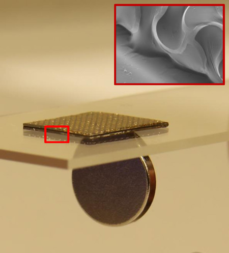
This paper introduces a ferromagnetic, folded, soft electrode composite material with capabilities in long-term usage and system-level integration in electrophysiological monitoring. Systematic investigations including studies of the ferromagnetism behaviors, the mechanical properties, the electrical interfaces to the skin, and the underlying materials aspects associated with their optimized construction. Electrodes based on these materials provide advantages in intimate, non-irritating contacts to the skin, dimensionally stable geometries and robust bonding to the skin and the measurement platforms. Detailed experimental measurements and theoretical modeling of the essential properties of the system, including interfaces to the skin, establish the key design consideration. These concepts have applicability to broad classes of skin-mounted electronic systems.
1. Introduction
Recent advances in materials for soft, dry electrodes and their demonstrated use in transcutaneous recording of electrophysiological signals suggest opportunities for continuous collection of data of relevance to healthcare and non-healthcare related applications alike [1–9]. For long-term use (i.e. several days) and minimized irritation at the skin interface in forms that provide for natural motions of the skin and body, an ideal electrode design should enable 1) conformal and robust contact to the skin, in a low-modulus design to eliminate mechanically induced discomfort and time-dependent effects associated with variation in hydration level[10–12], 2) mounting [7, 13, 14] on curvilinear surfaces of any region of the body [15] and 3) direct integration with advanced wireless electronics for data collection and communication [16]. The most widely adopted solution relies on conductive hydrogels, whose attractive features include low elastic moduli, biocompatible materials options and low interface impedances. Typically the hydrogel contacts the skin on one side and a solid metal recording electrode on the other [17, 18]. A key disadvantage is that the cross-linked hydrophilic polymer networks of the hydrogel can undergo dramatic dimensional changes when exposed to biofluids (e.g. sweat induced swelling) or when exposed to air (e.g. drying induced shrinkage). More recent alternatives involve dry, but soft and tacky, materials in which direct contact and/or capacitive coupling occurs between a conducting filamentary metal mesh supported by an ultralow modulus elastomer support. This composite structure can conform to the skin and accommodate natural motions, with an elastic response to strains up to several tens of percent and moduli that are substantially lower than those of the skin itself, in forms that are dimensionally stable when exposed to biofluids and air [7, 16]. Reversible integration with measurement systems requires, however, interconnects that are often cumbersome and fragile. Related approaches use nanomaterials (silver nanowires, graphene flakes, carbon nanotubes, etc.) coated on and/or embedded throughout the elastomer [19–24]. These options offer many attractive features, but precise dimensional control over the electrode geometries and interconnects can be difficult to achieve using existing manufacturing methods, and via connections for front to back side integration require specialized designs. Also, in most cases, the constituent nanomaterials are not commonly found in conventional electronics technologies.
In this paper, we present materials, integration strategies, and wireless electrophysiological recording demonstrations of an electrode structure that provides some key advantages over alternatives. The designs involve soft, composite layouts with embedded magnetic materials and a folded configuration. The result is a dry, long-lived interface to the skin, with reversible magnetic coupling to a separate measurement platform as a means to facilitate replacement, cleaning and re-use. Systematic studies of the materials, the mechanical properties, the contact impedances to the skin establish the fundamental aspects of this materials technology. Demonstrations in continuous wireless EEG, EMG, ECG and EOG recordings over several days establish the utility in practical applications.
2. Results and Discussion
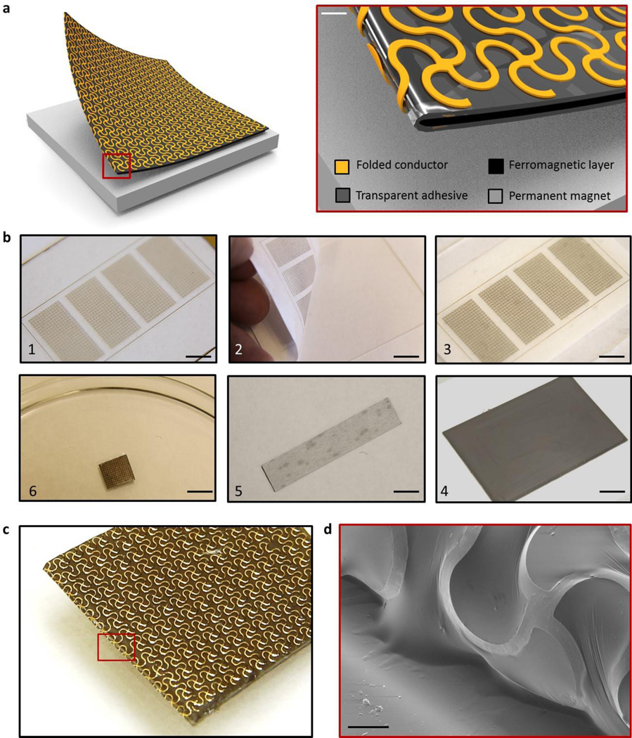
Figure 1 presents a schematic diagram that shows a representative ferromagnetic, folded composite structure resting on a thin permanent magnet (NdFeB). The electrode incorporates a thin, filamentary serpentine wire mesh (yellow) that bonds to and wraps around a soft ferromagnetic core (black) via a thin, tacky elastomer adhesive shell (grey). The mesh serves as the recording interface (direct or capacitive, depending on the absence or presence of a dielectric overcoat on the metal) and adopts a lithographically defined network design to allow biaxial stretchability. The exposed regions of the low modulus adhesive/ferromagnetic bi-layer provide adherent interfaces to the skin, with sufficient strength to maintain robust conformal contact under natural deformations associated with limb movements and muscle contractions. This contact prevents relative movement between the electrodes and the skin, thereby minimizing noise from motion artifacts. On the other side, the mesh electrically couples to a thin permanent magnet via a magnetic force of attraction that exceeds the strength of adhesion of the other side to the skin. The magnet also provides, on its back side, a permanent electrical bond to the recording hardware.
Figure 1. Ferromagnetic, folded, soft electrode composite.
(a) Schematic diagram of the electrode design and its magnified view, (b) Fabrication procedure; scale bar is 1cm, (c) An optical image and scanning electron microscope (SEM) image of fabricated electrode; scale bar is 100 µm.
Figure 1b shows a sequence of fabrication steps. As described in the Experimental Section, the mesh electrodes consist of filamentary traces with widths of 100 µm and thicknesses of 1~2 µm (200 nm Au / 10 nm Cr / 1.2 µm polyimide for direct contact; 1.2 µm polyimide / 200 nm Au / 10 nm Cr / 1.2 µm polyimide for capacitive contact). Fabrication involves photolithographic patterning of metals deposited by electron beam evaporation on a sacrificial layer of polymethylmethacrylate (PMMA, 1 µm). Immersing the sample into acetone for 1 hour allows retrieval of the mesh onto a water soluble tape. Spin coating and thermally curing a tacky, ultralow modulus formulation of a silicone polymer (Silbione Firm Gel, Bluestar Silicones, France, E= ~20 kPa) and a soft ferromagnetic composite formed by mixing uncured polymer with carbonyl iron (CI) powder (Sigma aldrich, USA, diameter= ~2 um), as shown as in figure 2, forms a bilayer on the exposed surface of the mesh. The spherical iron particles of the CI powder randomly mix and disperse in the silicone polymer matrix. The particles have varying numbers of concentric layers of α-iron between which cementite (Fe3C) stabilizes the structure [25]. The onion-like structure of the particles prevents the displacement of domain boundaries under an applied magnetic field. A result is that the magnetic hysteresis losses are very low [26]. As previously reported [27], CI particle-filled siloxane elastomers involve physical embedding of the particles without significant chemical interactions. The resulting composite maintains its magnetic properties up to temperatures of 150 °C, where amorphous layers of cementite prevent the crystalline phase of α-iron from oxidation [25]. Since the maximum temperature of the fabrication process outlined above is 70 °C, the CI particles retain their magnetic permeability.
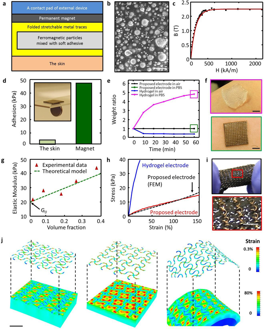
Figure 2. Physical properties of the electrode composite.
(a) Information on the structure of the composite and its interface with the skin and the contact pad of the external (or wearable) device. (b) SEM image of ferromagnetic (carbonyl iron) particles in an elastomer matrix; scale bar is 4 µm. (c) Magnetization curve of carbonyl iron powder. (d) Comparison of adhesion strength of the electrode composite to the skin and the magnet. Inset: image of the ferromagnetic properties of the electrode composite. (e, f) Effect of hydration on the proposed composite and on a commercially available hydrogel electrode. (g) Elastic modulus as a function of volume fraction of CI particles in the ferromagnetic composite. (h) Mechanical responses of the composite and a commercial hydrogel to applied strain. (i) Optical image of the electrode composite under stretching; scale bar is 1 mm. (j) Finite element study for uniaxial stretching (left), biaxial stretching (center), and folding (right); scale bars are 1 mm.
As shown in figure 1b, partially curing the polymers, folding the structure in half, completing the curing process and then dissolving the water soluble tape (immersion in water for 1 hour) yields stretchable magnetic electrodes. Figure 1c and 1d show an optical image of a sample and a scanning electron microscope image of the folded region.
In use, as shown in figure 2a, the electrode is in conformal contact with the skin on one side and with a thin magnet bonded to a wireless data acquisition and transmission system on the other. This configuration provides a mechancially compliant, electrically conductive channel, via the folded mesh, between the skin and the wireless system through the magnet. The middle layer, consisting of CI particles in a soft adhesive, silicone matrix, is magnetic and non-conductive [28]. Because the magnetic force exceeds the adhesion force, the system can be peeled away from the skin without delaminating the electrode from the wireless system. At the same time, the magnetic coupling allows reversible release of the electrode for cleaning or replacmeent. Figure 2b shows that the ferromagnetic particles in the elastomer matrix are nearly spherical in shape, with diameters between 1 to 3 µm and a mean of ~2 µm. As plotted in figure 2c, the magnetization curves obtained using a SQUID magnetometer indicate that the magnetization density rapidly increases with the strengh of the external magnetic field, and then saturates at 2.2 T when the field strength reaches at 600 kA/m. Under the action of an external magnetic field, each particle embedded in the elastomer can be magnetized to form a magnetic dipole. The resulting magnetization is further increased by the local magnetic fields exerted by surrounding particles. With this stong magnetic interaction, as shown in figure 2d, the fabricated electrode composite exhibits 10 times higher adhesion to the magnet (or device direction) than that of the skin [29–31]. Measurements of adhesion strength involve a peeling mode with a force guage (Mark-10, USA). Each reported result corresponds to an average of measurements on three samples.
As depicted in figure 2e and 2f, this type of magnetic stretchable electrode, unlike conventional hydrogel electrodes, retains its original weight when exposed to different levels of humidity. The dimensional instability of the hydrogel adversely affects adhesion strength, contact area, electrical impedance to the skin, and it leads to unpredictable sensor performance.
The soft mechanics is critically important for an intimate, non-irritating interface to the skin. Figure 2g summarizes results of measurements of the elastic modulus of ferromagnetic composite formulations with different volume fractions of CI particles. As the volume fraction increases, the resulting elastic modulus also increases, as might be expected. At the continuum level, the stiffness of a composite depends on some weighted combination of the stiffnesses of the individual constituent materials [32]. The experiments are, in fact, consistent with the Einstein theoretical model of the effective Young’s modulus of particle-filled solids, shown by the dotted green line. This model is simply: G =G0(1+2.5Φ), where G and G0 are the elastic moduli of a composite and a pure elastomeric material without particles and Φ is the volume fraction [33, 34]. As an electrode, lower modulus is desirable to provide free deformation and comformal contact with the the skin. At the same time, the electrode must offer sufficiently strong magnetic interaction to the magnet for secure integration. A balance of these considerations led to our choice of 0.1 volume fraction, which yields a material with modulus comparable to the skin (E = ~130kPa) and an attractive force of interaction with the magnet that is significantly higher than that associated with adhesion to the skin.
As plotted in figure 2h–i, the full electrode structure also has a low modulus, elastic behavior under large strain deformation. The total stretchabillity (more than 150 %) and skin-like modulus (E = ~40 kPa) are key characteristics. Figures 2 j, k and l show the deformed shapes and distributions of strain determined by three dimensional finite element analysis under uniaxial/biaxial stretching and bending. The serpentine design leads to strains in the electrode materials that are ~2 orders of magnitude smaller than those in the elastomers. The uniaxial/biaxial elastic stretchability and bendability are 25 %, 24 %, and 0.46 mm−1, respectively, for ~0.3 % yield strain of Au.
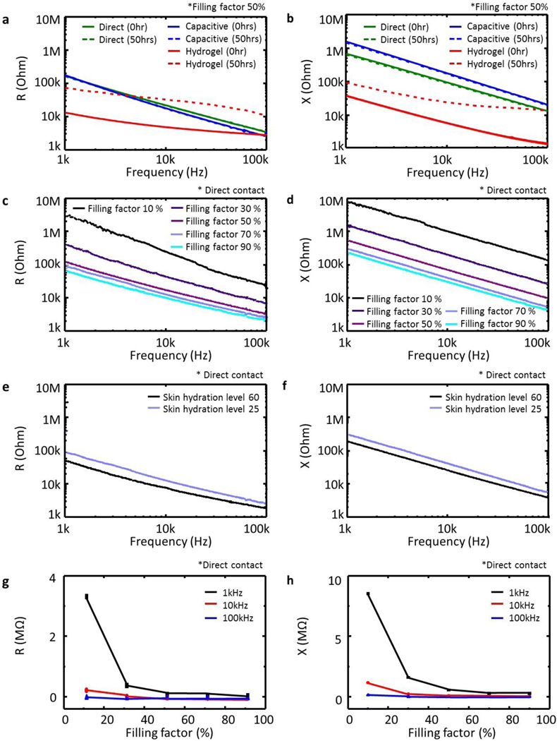
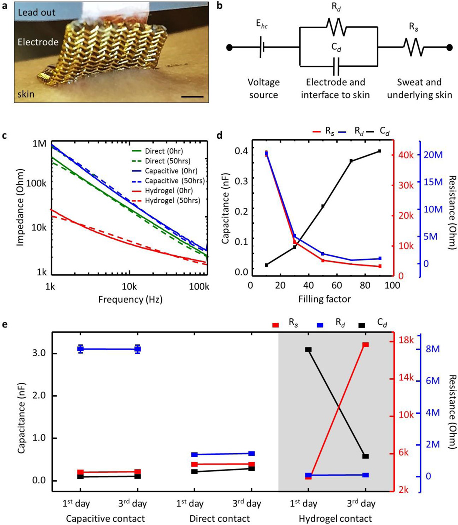
Accurate and reliable recording of EP signals benefits from low impedance, temporally stable contacts to the skin. As a summary of results, figure 3a–h present the measured impedance to the skin for various parameters: electrode type, filling factor, skin hydration, and frequency. The measurements involve a pair of identical electrodes (contact area = 1 cm by 1 cm; distance between two electrodes = 5 cm) laminated on the flexor carpi radialis of the forearm. Figure 3a–b present results for different types of electrodes. The commercial hydrogel electrode exhibits lower impedance than direct or capacitive magnetic stretchable electrodes (measured with comparable overall areas, rather than just electrical interface areas) but its impedance significantly increases after 50 hours due to effects of shrinkage and evaporative drying while that of the other electrodes remains constant. The magnetic stretchable electrodes have impedances that depend on filling factor (active sensing component, as defined by the area of the serpentine structure, to total electrode area), skin hydration level, and frequency. The impedances show a linear dependence on frequency in log-log scale as shown in figure 3c–f, and an inverse dependence on filling factor in linear-linear scale as shown in figure 3g–h. A simple equivalent circuit model yields some insights. As in figure 4a, the electrodes lie between the electrical lead-out (or thin magnet bonded on contact pad) and the skin (or epidermis). The associated model is in figure 4b [35, 36]. Here, the voltage source Ehc corresponds to the half cell potential, the capacitance Cd indicates the electrical charge accumulated between the electrode and the skin, Rd is the resistance between the electrode and the skin during the charge transfer, and Rs is related to the sweat and the underlying skin tissue, such as epidermis, dermis, and subcutaneous layers. The resistance of the sweat and underlying skin tissue (Rs) should be in series with Rd and Cd. In this model, the electrochemical impedance, current variance caused by sinusoidal potential perturbation, is simplified by two components of the charge transfer (faradaic current) and double layer capacitance on the surface of the electrode. The resistance in sweat and tissue affects the total impedance since both the charge transfer and capacitance depends on the solution resistance, Rs. However, Rs, alone itself, cannot be an independent current path. In this study, we chose the equivalent circuit model from reference [35]. This model is the most simplified version to describe electrochemical impedance of the electrode in electrolyte. The reference has similar geometrical configuration and resulting electrical impedance of their electrode to those of our electrode. As in figure 4c, fits to the data (Levenberg-Marquadt algorithm) yield values for the key parametrs. In figure 4d, as the areal filling factor increases, the capacitance also increases but both resistances decrease. This analysis indicates that larger active sensing areas provide higher capacitances and lower resistances, as might be expected. As presented in figure 4e, the model parameters remain constant over several days, in contrast to those for hydrogel electrodes. A commercially available hydrogel electrode (AG735, Axelgaard Manufacturing, USA) provides a useful point of comparison. As shown in figure 4e, the fitted Rd, Cd, and Rs values of the hydrogel electrode with the circuit model are 0.12 Mohm, 0.2 nF, 3.1 kohm, consistent with previous reports (Rd, = 0.1~1 Mohm; Cd = 0.1~10 nF; Rs = 0.1~10 kohm) [37, 38]. These parameters, of course, depend on the geometries of the electrodes and the chemical composition of the hydrogel.
Figure 3. Impedance measurements associated with contact between the electrodes and the skin.
(a, b) Type of contact: direct, capacitive, hydrogel. (c, d) Filling factor of direct contact area to entire electrode, (e, f) skin hydration level, (g, h) frequency. Dotted lines present fitted curves to the measured data.
Figure 4. Impedance analysis with equivalent circuit model.
(a) Optical image of electrode system on the skin, and (b) equivalent circuit model. (c) Measured impedance data and their fitted curve. (d) Extracted parameters according to filling factor, (e) type of electrode and elapsed time.
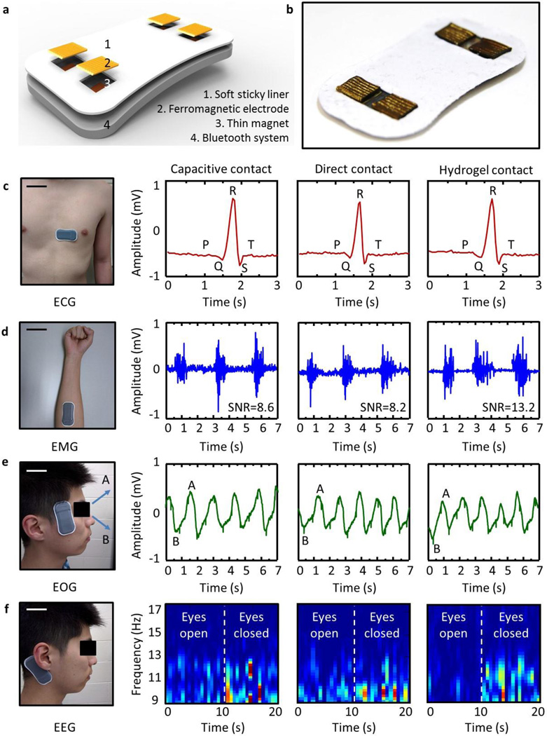
Figure 5a–b present a schematic diagram and an optical image of these electrodes integrated with a thin, stretchable recording platform with wireless operation (BiostampRC, MC10, Inc). Each electrode mounts to a thin permanent magnet (NdFeB) with a force that provides reliable electrical contact and mechanical coupling. A conductive epoxy (CircuitWorks, CW2400, USA) bonds the magnets to solid metal pads on the BiostampRC, with negligible resistance (<0.001 ohm-cm). The shell elastomer serves as a soft adhesive (Silbione Firm Gel, Bluestar Silicones, France, E= ~20kPa) to the skin. In this way, various EP signals, including electrocardiogram (ECG), electromyogram (EMG), electroocoloculogram (EOG), and electrocepharlogram (EEG) can be captured and stored locally in the BiostampRC memory module or continuously transmitted to an external receiver via a Bluetooth protocol. In this experiments, we used two different BiostampRC devices. Compared to the device for capacitive contact, the other one for hydrogel and direct contact is designed to have a compensative capacitor to analog front end of the device. With this target-oriented circuit modification, EP signals are successfully collected. Figure 5c–f summarizes results of various experiments. As a first example, ECG signals aquired with both capacitive- and direct contact electrodes from the chest show clearly the P wave, the QRS complex and the T wave with a quality of measurement that is comparable to that of data using hydrogel electrode. EMG signals captured from the flexor carpi radialis of the forearm show similarly high quality. In this case, the signal to noise ratio (SNR) ranges from 8.2 to 13, suitable for use in both clinical applications and human-machine-interfaces (HMI) [9, 39]. Placing the device near the left or right eyes allows recording of EOG signals. The experiments involved data collection while the subject moved his eyes up and down. As can be seen in figure 5e, the data capture eye movement accurately, with potential for use in ophthalmological diagnosis in training procedures and in human machine interfaces. As a last example, EEG signal collected with a device on the mastoid clearly shows alpha rhythms with frequencies between 8 ~12 Hz when the eyes are closed, of potential relevance in cognitive state monitoring and brain computer interfaces [39].
Figure 5. Device-level integration of the proposed electrode composite.
(a) Schematic illustrations and (b) optical images of wireless electrophysiology (EP) monitoring systems integrated with soft, folded magnetic electrode composites. Optical images of the device on the body and associated captured EP data: (c) electrocardiogram (ECG), (d) electromyogram (EMG), (e) electrooculogram (EOG), and (f) electroencephalogram (EEG). Scare bars are 10 cm in (c, d) and 5cm (e, f).
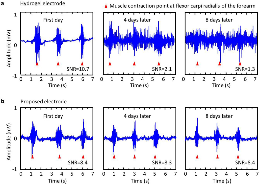
A series of experiments of wireless EMG monitoring highlight long-term usability of the system. As in figure 6, the quality of EMG signal from the flexor carpi radialis of the forearm recorded with a hydrogel electrode degrade quickly due to unavoidable evaporation of water. The signals and their SNR value captured using these dry, soft magnetic electrodes maintain their original quality. The limit of detection of their electromyogram are ~0.05mV for capacitive contact electrode, ~0.04mV for direct contact electrode, 0.01 mV for fresh hydrogel contact electrode, and 0.5mV for dried (8 days later) hydrogel contact electrode in room temperature and atmosphere. In this case, the sensitivity levels which means EMG response amplitude for almost same muscle groups for similar activities are similar for each case.
Figure 6. Long-term usability with wireless EMG recording.
Data captured using (a) a hydrogel electrode, (b) soft, folded magnetic electrode. Each red triangle indicates a specific point of muscle contraction of the flexor carpi radialis of the forearm.
3. Conclusion
The materials, designs and integration strategies presented here provide a framework for ferromagnetic, folded, soft electrodes with capabilities in long-term use and system-level integration in EP monitoring. The main advantages of this system are in 1) intimate and persistent contact to the skin, without irritation, 2) dimensionally stable, engineered designs for robust adhesion and electrical measurement interfaces to the skin, 3) direct and reversible bonding to external wireless recording/transmission electronics by magnetic force. As an advanced form of epidermal electronics, these design schemes are fully compatible with the most sophisticated EP monitoring system that are commercially available. These same concepts can apply to many other types of epidermal electronics with various other measurement modalities, including those that involve thermal, mechanical and chemical sensing.
4. Experimental Section
Fabrication of the electrode composite
Polymethylmethacrylate (PMMA, 100 nm) coated on a glass slide (70 × 50 × 1.0 mm3) served as a sacrificial layer to facilitate release. Spin casting and thermal curing (2 hours at 250 °C in a vacuum oven) a film of polyimide (PI; 2 µm in thickness, HD Microsystems, USA) yielded an overcoat on the PMMA. Photolithographic patterning of bi-layers of Cr (10 nm) / Au (200 um) formed by electron beam evaporation (AJA International, USA) defined the conductive elements of the mesh. Reactive ion etching (RIE, 50 mTorr, 40 sccm CF4, 100 W for 10 min) of the exposed PI created an open architecture layout to provide mechanical stretchability and exposed regions to facilitate adhesion to the skin. Undercutting removed the PMMA layer to allow release onto a water-soluble tape (Aquasol, USA) for subsequent integration with a pre-strained compliant and sticky elastomeric substrate (Silbione Firm Gel, Bluestar Silicones, France, E= ~20 kPa). Spin-casting a layer of silbione and a layer of soft adhesive formed by mixing carbonyl iron powder with uncured silbione at a 1:9 ratio by volume, formed a bilayer on the surface of the tape. Partially curing these materials by heating to 70°C in an oven for 10 hours, folding electrode in half and then completing the cure by continued baking for 24 hours completed the fabrication. Dissolving the water-soluble tape by dipping the samples into water and drying them at room temperature and atmosphere prepared the electrodes for integration with the recording apparatus and the skin.
Measurements of magnetization
The magnetization curves of the electrode composite were determined with a superconducting quantum interference device magnetometer (S600X SQUID susceptometer, UK).
Measurements of stress-strain responses
Mechanical properties of all samples were measured with a dynamic mechanical analyzer (DMA; TA instruments, Q800). Characterizing the applied force versus the displacement under uniaxial tensile loading at room temperature yielded data for determination of the mechanical modulus. Each of the reported results corresponds to an average of measurements on three samples.
Finite element analysis
ABAQUS commercial software [40] was used to study the mechanics of a mesh electrode [200 nm-thick Au (elastic modulus 80GPa and Poisson’s ratio 0.44)/1.2 µm-thick PI (elastic modulus 2.5GPa and Poisson’s ratio 0.34)] on a bi-layer substrate [0.5 mm-thick layer of silbione (elastic modulus ~20 kPa and Poisson’s ratio 0.5)/0.5 mm-thick ferromagnetic layer (elastic modulus ~30 kPa and Poisson’s ratio 0.5)]. Eight-node three-dimensional solid elements and four-node shell elements were used for the bi-layer substrate and electrode, respectively, with refined meshes to ensure the accuracy.
Measurement of electrical impedance
Quantitative analysis of electrical impedances between the stretchable magnetic electrodes and the skin over a frequency range of 1 to 100 kHz was performed with a precision LCR meter (Agilent, E4980A, USA).
Device-level integration of the stretchable magnetic electrodes
Bonding and room temperature curing of thin (2 mm) permanent magnets (NdFeB) onto contact pads of on a BiostampRC monitoring system utilized a conductive epoxy (CircuitWorks, CW2400, USA). Assembling the electrode composites onto the magnets relied on magnetic interactions between these two components. An adhesive, fabric liner bonded the non-electrode regions of the BiostampRC platform to the skin.
Experiments on Human Subjects
All experiments on human skin were conducted under approval from Institutional Review Board at the University of Illinois at Urbana-Champaign (protocol number: 13229).
Acknowledgments
This work used facilities in the Frederick Seitz Materials Research Laboratory and the Center for Microanalysis of Materials at the University of Illinois at Urbana-Champaign. Y. M. and X. F. acknowledge the support from the National Basic Research Program of China (Grant No. 2015CB351900) and National Natural Science Foundation of China (Grant Nos.11402135, 11320101001). YH acknowledges the support from NSF (DMR-1121262, CMMI-1300846 and CMMI-1400169) and the NIH (grant no. R01EB019337).
Footnotes
Supporting Information
Supporting Information is available from the Wiley Online Library or from the author.
Contributor Information
Prof. Kyung-In Jang, Department of Materials Science and Engineering, Frederick Seitz Materials Research Laboratory, University of Illinois at Urbana-Champaign, Urbana, IL 61801, USA; Department of Robotics Engineering, Daegu Gyeongbuk Institute of Science and Technology (DGIST), Daegu 42988, Korea.
Han Na Jung, Department of Materials Science and Engineering, Frederick Seitz Materials Research Laboratory, University of Illinois at Urbana-Champaign, Urbana, IL 61801, USA.
Dr. Jung Woo Lee, Department of Materials Science and Engineering, Frederick Seitz Materials Research Laboratory, University of Illinois at Urbana-Champaign, Urbana, IL 61801, USA Department of Material Science and Engineering, Department of Energy Engineering, Hanyang University, Seoul, 133-791, Republic of Korea.
Prof. Sheng Xu, Department of NanoEngineering, University of California at San Diego, La Jolla, CA 92093, USA
Yu Hao Liu, Department of Materials Science and Engineering, Frederick Seitz Materials Research Laboratory, University of Illinois at Urbana-Champaign, Urbana, IL 61801, USA.
Dr. Yinji Ma, Department of Engineering Mechanics, Center for Mechanics and Materials, Tsinghua University, Beijing 100084, China Department of Civil and Environmental Engineering, Mechanical Engineering, Materials Science and Engineering, Northwestern University, Evanston, IL 60208, USA.
Prof. Jae-Woong Jeong, Department of Electrical, Computer, and Energy Engineering, University of Colorado, Boulder, CO 80309, USA
Prof. Young Min Song, School of Electrical Engineering and Computer Science, Gwangju Institute of Science and Technology, Gwangju 61005, Republic of Korea
Dr. Jeonghyun Kim, Department of Materials Science and Engineering, Frederick Seitz Materials Research Laboratory, University of Illinois at Urbana-Champaign, Urbana, IL 61801, USA Department of Material Science and Engineering, Department of Energy Engineering, Hanyang University, Seoul, 133-791, Republic of Korea.
Dr. Bong Hun Kim, Department of Materials Science and Engineering, Frederick Seitz Materials Research Laboratory, University of Illinois at Urbana-Champaign, Urbana, IL 61801, USA
Anthony Banks, Department of Materials Science and Engineering, Frederick Seitz Materials Research Laboratory, University of Illinois at Urbana-Champaign, Urbana, IL 61801, USA.
Jean Won Kwak, Department of Materials Science and Engineering, Frederick Seitz Materials Research Laboratory, University of Illinois at Urbana-Champaign, Urbana, IL 61801, USA.
Yiyuan Yang, Department of Materials Science and Engineering, Frederick Seitz Materials Research Laboratory, University of Illinois at Urbana-Champaign, Urbana, IL 61801, USA.
Dawei Shi, Department of Materials Science and Engineering, Frederick Seitz Materials Research Laboratory, University of Illinois at Urbana-Champaign, Urbana, IL 61801, USA.
Zijun Wei, Department of Materials Science and Engineering, Frederick Seitz Materials Research Laboratory, University of Illinois at Urbana-Champaign, Urbana, IL 61801, USA.
Prof. Xue Feng, Department of Engineering Mechanics, Center for Mechanics and Materials, Tsinghua University, Beijing 100084, China
Prof. Ungyu Paik, Department of Material Science and Engineering, Department of Energy Engineering, Hanyang University, Seoul, 133-791, Republic of Korea
Prof. Yonggang Huang, Department of Civil and Environmental Engineering, Mechanical Engineering, Materials Science and Engineering, Northwestern University, Evanston, IL 60208, USA
Dr. Roozbeh Ghaffari, MC10 Inc., Cambridge, MA 02140, USA
Prof. John A. Rogers, Department of Materials Science and Engineering, Frederick Seitz Materials Research Laboratory, University of Illinois at Urbana-Champaign, Urbana, IL 61801, USA.
References
- 1.Chi YM, Jung T-P, Cauwenberghs G. IEEE Rev. Biomed. Eng. 2010;3:106. doi: 10.1109/RBME.2010.2084078. [DOI] [PubMed] [Google Scholar]
- 2.Myers AC, Huang H, Zhu Y. RSC Adv. 2015;5:11627. [Google Scholar]
- 3.Hairston WD, Whitaker KW, Ries AJ, Vettel JM, Bradford JC, Kerick SE, McDowell K. J. Neural Eng. 2014;11:046018. doi: 10.1088/1741-2560/11/4/046018. [DOI] [PubMed] [Google Scholar]
- 4.Searle A, Kirkup L. Physiol. Meas. 2000;21:271. doi: 10.1088/0967-3334/21/2/307. [DOI] [PubMed] [Google Scholar]
- 5.Mukhopadhyay SC. Wearable Electronics Sensors For Safe and Healthy Living. Switzerland: Springer; 2015. [Google Scholar]
- 6.Rogers JA, Ghaffari R, Kim D-H. Stretchable Bioelectronics for Medical Devices and Systems. Switzerland: Springer; 2016. [Google Scholar]
- 7.Kim DH, Lu NS, Ma R, Kim YS, Kim RH, Wang SD, Wu J, Won SM, Tao H, Islam A, Yu KJ, Kim TI, Chowdhury R, Ying M, Xu LZ, Li M, Chung HJ, Keum H, McCormick M, Liu P, Zhang YW, Omenetto FG, Huang YG, Coleman T, Rogers JA. Science. 2011;333:838. doi: 10.1126/science.1206157. [DOI] [PubMed] [Google Scholar]
- 8.Smith S. J. Neurol. Neurosurg. Phychiatry. 2005;76:ii2. doi: 10.1136/jnnp.2005.069245. [DOI] [PMC free article] [PubMed] [Google Scholar]
- 9.Jeong JW, Yeo WH, Akhtar A, Norton JJS, Kwack YJ, Li S, Jung SY, Su YW, Lee W, Xia J, Cheng HY, Huang YG, Choi WS, Bretl T, Rogers JA. Adv. Mater. 2013;25:6839. doi: 10.1002/adma.201301921. [DOI] [PubMed] [Google Scholar]
- 10.du Plessis J, Stefaniak A, Eloff F, John S, Agner T, Chou TC, Nixon R, Steiner M, Franken A, Kudla I, Holness L. Skin Res. Technol. 2013;19:265. doi: 10.1111/srt.12037. [DOI] [PMC free article] [PubMed] [Google Scholar]
- 11.Blichmann C, Serup J. Contact Dermatitis. 1987;16:155. doi: 10.1111/j.1600-0536.1987.tb01411.x. [DOI] [PubMed] [Google Scholar]
- 12.Huang X, Yeo WH, Liu YH, Rogers JA. Biointerphases. 2012;7:52. doi: 10.1007/s13758-012-0052-8. [DOI] [PubMed] [Google Scholar]
- 13.Yeo WH, Kim YS, Lee J, Ameen A, Shi LK, Li M, Wang SD, Ma R, Jin SH, Kang Z, Huang YG, Rogers JA. Adv. Mater. 2013;25:2773. doi: 10.1002/adma.201204426. [DOI] [PubMed] [Google Scholar]
- 14.Yang SX, Chen YC, Nicolini L, Pasupathy P, Sacks J, Su B, Yang R, Sanchez D, Chang YF, Wang PL, Schnyer D, Neikirk D, Lu NS. Adv. Mater. 2015;27:6423. doi: 10.1002/adma.201502386. [DOI] [PubMed] [Google Scholar]
- 15.Igarashi T, Nishino L, Nayar SK. The Appearance of Human Skin: A Survey. NY, USA: Now Publishers Inc; 2007. [Google Scholar]
- 16.Jeong JW, Kim MK, Cheng HY, Yeo WH, Huang X, Liu YH, Zhang YH, Huang YG, Rogers JA. Adv. Healthc. Mater. 2014;3:642. doi: 10.1002/adhm.201300334. [DOI] [PubMed] [Google Scholar]
- 17.Calo E, Khutory anskil VV. Eur. Polym. J. 2015;65:252. [Google Scholar]
- 18.Alba NA, Sclabassi RJ, Sun MG, Cui XT. IEEE Trans. Neural Syst. Rehabil. Eng. 2010;18:415. doi: 10.1109/TNSRE.2010.2048579. [DOI] [PubMed] [Google Scholar]
- 19.Myers A, Du L, Huang H, Zhu Y. IEEE Engineering in Medicine and Biology Society Conference Proceedings; 2014. p. 1. [Google Scholar]
- 20.Myers A, Du L, Huang H, Zhu Y. RSC Adv. 2015;5:11627. [Google Scholar]
- 21.Lee SM, Byeon HJ, Lee JH, Baek DH, Lee KH, Hong JS, Lee S-H. Sci. Rep. 2014;4:6074. doi: 10.1038/srep06074. [DOI] [PMC free article] [PubMed] [Google Scholar]
- 22.Yapici MK, Tamador AA, Samad YA, Liao K. Sensor Actuat. B-Chem. 2015;221:1469. [Google Scholar]
- 23.Jung HC, Moon JH, Baek DH, Lee JH, Choi YY, Hong JS, Lee S-H. IEEE T. Bio.-Med. Eng. 2012;59:1472. doi: 10.1109/TBME.2012.2190288. [DOI] [PubMed] [Google Scholar]
- 24.Lee JH, Nam YW, Jung HC, Baek DH, Lee SH, Hong JS. Biochip J. 2012;6:91. [Google Scholar]
- 25.Abshinova MA, Kuritka L, Kazantseva NE, Vilcakova J, Saha P. Mater. Chem. Phys. 2008;114:78. [Google Scholar]
- 26.Syrkin VG, Tolmasskii S, Petrova AA. Sov. Powder Metall. 1966;5:545. [Google Scholar]
- 27.Neto FND, Araujo OA, Guilherme LR, Garg VK, Oliveira AC, de Souza PEN, Franco A. Mater. Chem. Phys. 2015;162:100. [Google Scholar]
- 28.Bica I. J. Ind. Eng. Chem. 2009;15:605. [Google Scholar]
- 29.Jolly RM, Carlson JD, Munoz BC. Smart Mater. Struct. 1996;5:607. [Google Scholar]
- 30.Jang K-I, Seok J, Min B-K, Lee SJ. J. Magn. Magn. Mater. 2009;321:1167. [Google Scholar]
- 31.Bellan C, Bossis G. Int. J. Mod. Phys. B. 2002;16:2447. [Google Scholar]
- 32.Jörgen SB, Mary CB. Rubber Chem. Technol. 1999;72:633. [Google Scholar]
- 33.Einstein A. Ann. Phys. 1906;19:229. [Google Scholar]
- 34.Smallwood HM. J. Appl. Phys. 1944;15:758. [Google Scholar]
- 35.Oliveira CC, de Silva JM, Trindade IG, Martines F. Conference on Design of Circuits and Integrated Circuits; 2014. p. 1. [Google Scholar]
- 36.Meziane N, Webster JG, Attari M, Nimunkar AJ. Physiol. Meas. 2013;34:R47. doi: 10.1088/0967-3334/34/9/r47. [DOI] [PubMed] [Google Scholar]
- 37.Albulbul A, Chan ADC. IEEE International Symposium on Medical Measurements and Applications Proceedings; 2012. p. 1. [Google Scholar]
- 38.Taji B, Shirmohammadi S, Groza V, Batkin I. IEEE Trans. Instrum. Meas. 2014;63:1412. [Google Scholar]
- 39.Nicholas-Alonso LF, Gomez-Gil J. Sensors. 2012;12:1211. doi: 10.3390/s120201211. [DOI] [PMC free article] [PubMed] [Google Scholar]
- 40.ABAQUS Analysis User’s Manual 2010, V6.10 [Google Scholar]


