Abstract
In vivo imaging of cerebral vasculature and blood flow provides highly valuable information for clinicians as well as researchers. Nevertheless, currently available methods are complex, time-consuming and expensive. Here, we present a novel, minimally invasive method for vascular imaging through the sufficiently transparent intact skull of young mice. Our method combines laser speckle and fluorescent imaging with dynamic color mapping and image fusion. Quickly generated wide-field images present clear visual information on blood flow and perfusion in the cerebral cortex and meninges. The ability of the method to visualize hemodynamic changes is demonstrated by induced occlusion of the middle cerebral artery. The compact and easily operated system comprises of several pieces of standard and affordable laboratory equipment. This simple, robust and inexpensive method may become an important tool for assessment of brain hemodynamics in preclinical studies.
In vivo imaging of the cortical blood vessels is essential for assessment of brain function under varying conditions in both clinical and experimental settings. Although there is a variety of optical imaging modalities that are used for this purpose, such as optical coherence tomography1, photoacoustic microscopy2, photoacoustic tomography3 multiphoton microscopy4 and hybrid methods such as laser speckle and fluorescence5,6,7, imaging of cerebral blood vessels through the intact skull remains challenging. Limitations such as the necessity to remove part of the skull or expensive equipment restrict the use of this procedure in settings such as preclinical trials.
Laser speckle imaging (LS), also known as laser speckle contrast imaging8, is widely used to visualize the vasculature, blood flow and perfusion in various biomedical applications9,10, including transcranial imaging of major brain vessels11. LS, which is based on dynamic scattering of diffusively reflected laser light, is sensitive to the movement of red blood cells inside vessels and can therefore be applied for continuous imaging of blood flow dynamics.
Fluorescence angiography is extensively used in many biomedical applications especially in ophthalmology12. This modality follows the temporal distribution and redistribution of a fluorescent material through the vasculature and thereby provides valuable information about hemodynamics13.
Color mapping is widely used to display various type of scientific information including information related to dynamic processes in time14 or in case of multimodal image fusion15. The purpose of using color mapping is to convey detailed information in a way that is easily understandable to the viewer.
The IHS (intensity, hue, saturation) color model is one of the most widely used in computer vision16. Intensity refers to the brightness of the color, hue is the dominant wavelength of light, which is the perceived color, and saturation is to the purity of the color. In the application of this model, real-world data such as various biological variables are encoded by the three color attributes. Color mapping of imaging data enhances the visibility of blood vessels, facilitates distinction between arteries and veins and enables assessment of perfusion level and vascular permeability and detection of flow abnormalities. The usage of color coding to enhance visibility of blood vessels after administration of contrast materials has been successfully demonstrated17,18
Here, we present a new method that simplifies transcranial vascular imaging in preclinical studies. The method we term transcranial optical vascular imaging (TOVI) combines laser speckle and dynamic fluorescent imaging (referred to hereafter as DF), which is a slightly modified version of fluorescence angiography, followed by computer-assisted dynamic color mapping of the acquired data. Finally, color-coded hybrid images combine data acquired by both DF and LS to clearly present valuable information on cerebral perfusion, enabling to identify and analyze aberrations. TOVI operates at a cranial thickness of up to 250 µm and can therefore be used transcranially in mice until the age of 6 months. Because the skull remains intact, there is no injury to the meninges or underlying brain tissues and the unperturbed cortical circulation of an animal can be followed through entire experiments.
Results
General description of the method
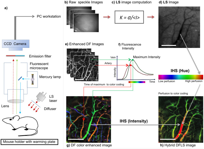
The setup is shown in Figure 1a (for technical details, see Methods). Both the LS and DF modalities use the same lens, optical path and charge-coupled device (CCD) camera. The anesthetized animal is placed inside the mouse holder. Unlike in other methods, no special mounting media is necessary. Then, stacks of raw LS images (Fig. 1b and Supplementary Fig. S1a,b), are streamed to a PC workstation and undergo computation using the formula shown in Fig. 1c. In the resulting images, functional blood vessels (larger than capillaries) are seen as darker areas (Fig. 1d, Supplementary Fig. S1c,d). The hemodynamic data provided by the LS mode is used to identify the optimal time point for administration of the fluorescent probe and thereby enhance the efficacy of DF. For example, in the acute cerebral ischemic event described in the following, LS-obtained data were used to verify effective artery occlusion and the administration of contrast material was timed accordingly.
Figure 1. TOVI setup and principles of operation.
(a) Schematic of the imaging setup. The animal is placed under the lens on a special mouse holder with a warming plate, which maintains body temperature at 37°C. TOVI equipment includes a standard fluorescent zoom microscope, a lamp and an emission filter; the laser module is coupled with an optical diffuser. Images captured by a CCD camera are saved as a raw stacked 16-bit tiff files on a PC-based workstation. (b) Raw speckle images. (c) Computation of LS images. The mathematical formula K = σ/<I> is applied to calculated contrast in each pixel (see Methods). (d) LS image, In the processed image on the right, darker areas correlate with higher blood flow, corresponding with blood vessels (e) Enhanced fluorescent images are acquired by the same camera during a 10 second interval after fluorescent material administration. Following a noise elimination procedure (see Methods), for each pixel the frame (i.e. time point) of maximum intensity projection (MIP) is identified. (f) Graph shows florescence intensity as a function of time, illustrating the difference in arrival time between arteries (red) and veins (green). (g) DF color enhanced image, which is color-coded using the IHS, color model. Hue encodes time of maximal pixel intensity, whereas MIP is encoded as intensity and saturation. (h) Hybrid DFLS image. In the hybrid (DFLS) mode, data from both modalities are fused, as LS contrast level is encoded as hue and MIP levels from DF mode are encoded as intensity and saturation. (Drawing by V.K).
Next, during a 20 second interval after intravenous fluorescein injection, raw DF images are acquired and streamed to the same PC. In the raw fluorescent image, blood vessels appear as brighter areas (data not shown). Then, raw DF images are enhanced (see Methods) to show the fine details (Fig. 1e). In the enhanced images, fluorescence intensity is plotted as a function of time (Fig. 1f). Since the maximal fluorescence signal is detected in arteries approximately 1 second post-injection, as compared to 1.5 seconds in veins, various types of information on blood vessel kinetics can be extracted. The continuous DF data can also be recorded frame by frame as a video sequence showing the kinetics of blood flow (Supplementary Movies 1 and 2).
Importantly, we tested our method on mice at different ages and with different parietal cranial bone thicknesses. As verified by ex vivo micro-CT measurements, both LS and DF modalities can be used transcranially at a thickness of up to 250 µm, corresponding with 6 months of age in the mouse model that we used (data not shown). This implies that TOVI enables in vivo visualization of the unperturbed cortical hemodynamics through the intact skull using this animal model.
The next computational stage produces a DF image-based color-coded vascular map (details in Methods and Supplementary Figs. S2, S3, S4). In the IHS color map, hue represents the time point of maximum fluorescence whereas intensity and saturation encode the maximum level of fluorescence. Thus, the color map demonstrates temporal information about blood flow. Because of the difference in arrival time of fluorescent material between arteries and veins, the main cortical arteries appear in red-orange, major cortical veins appear in yellow-green and cranial veins in blue-purple (Fig. 1g). Finally, in the hybrid DFLS mode, the IHS color model is used again to produce color mapping of perfusion based on data acquired by both modalities. This time, the maximum fluorescence level (known as maximum intensity projection, MIP) is calculated from the whole stack of DF images and is encoded as intensity and saturation, whereas the laser speckle contrast extracted from LS images is encoded as hue. This means that areas with high perfusion are seen in red (Fig. 1h and Supplementary Fig. S5).
The combination of LS and DF imaging enables transcranial visualization of two additional important aspects of the cortical blood flow. The flow in vessels is detected by LSI, whereas the exact origin of the vessel in the vascular hierarchy, from arteries through venules to veins, is clearly seen in the DF color-enhanced image. The combination of the two modes with IHS provides a hybrid image of perfusion, which shows the flow superimposed on a detailed vascular anatomy image.
Proof of concept: Monitoring perfusion during acute cerebral ischemic event
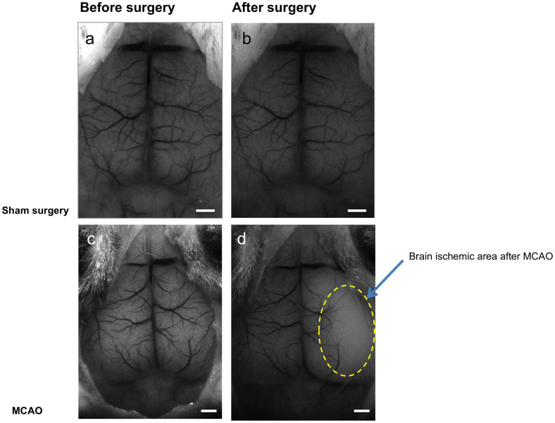
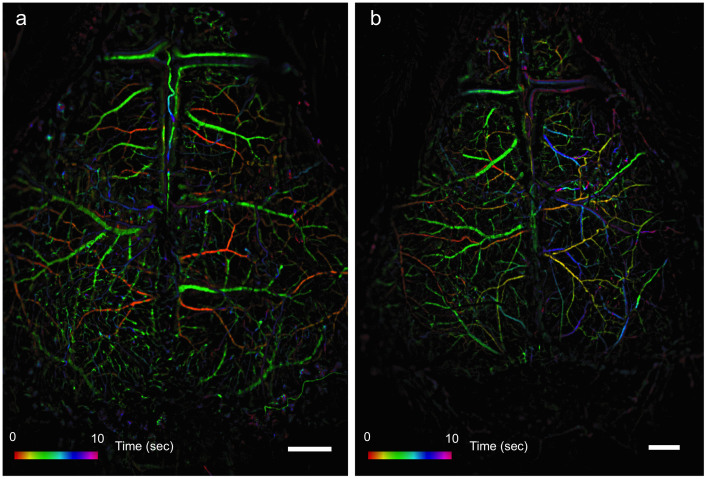
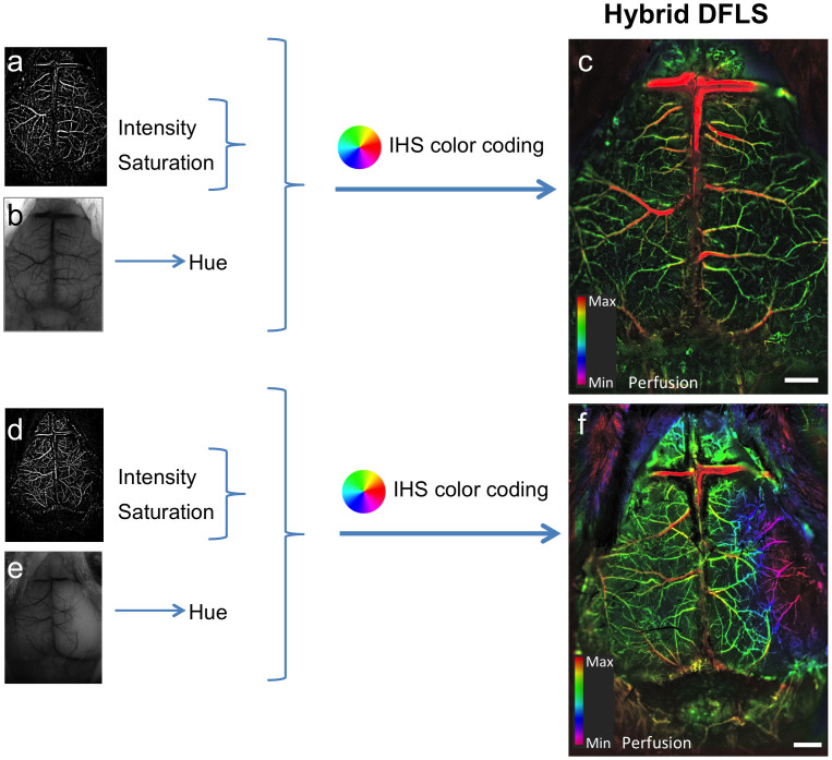
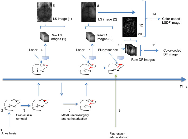
To demonstrate the potential of the system to visualize hemodynamic changes and particularly perturbations in cerebral blood flow, an acute cerebral ischemic event (an ischemic stroke-like situation) was induced by occlusion of the middle cerebral artery (MCA) of mice using a filament model. Images of a mouse that underwent a sham surgery as a control were compared to images of a mouse that underwent MCAO. After occlusion, data were collected continuously using the LS mode to identify the right moment to inject the fluorescent material, namely when perfusion is affected. Figure 2 shows LS images acquired before and after surgery. Once an effective occlusion has been verified by the LS images (Fig. 2d and Supplementary Fig. S1d), contrast material was administered. The effect of the occlusion on perfusion in the right hemisphere is clearly seen in the dynamic color-mapped panoramic DF image (Fig. 3 and Supplementary Movie 2). Hybrid DFLS image (Fig. 4) clearly demonstrates the area of lesion in the right hemisphere. Flowchart and timeline of the entire experimental procedure are shown in Fig. 5.
Figure 2. LS images of middle cerebral artery occlusion.
Images obtained by LS imaging show ischemic effect on cortical blood flow following MCAO surgery. (a,b) Images of a control mouse brain before (a) and after (b) sham surgery. (c,d) Images of a mouse brain before (c) and 10 minutes after (d) MCAO surgery. Yellow dashed line in d demarcates area of brain ischemia after MCAO. Scale bars, 1 mm.
Figure 3. DF images of middle cerebral artery occlusion.
Images obtained by DF imaging show ischemic effect on cortical blood flow following MCAO surgery in the same mice shown in Fig. 2. (a) Image of a control mouse brain undergoing sham surgery. (b) Image of a mouse with MCAO. Scale bars are 1 mm. Colored bars represent time (in seconds) from fluorescein administration.
Figure 4. Visualization of hemodynamic changes during an acute ischemic event.
Color-enhanced hybrid images combining both LS and DF data show the effects of induced MCAO on a mouse brain. DF (MIP, a) and LS (b) images are merged and color-coded to create a hybrid image of cortical blood flow. (a–c) Images of the cortical vasculature of a control mouse. (d–f) Images of the cortical vasculature following occlusion; the lesion in the affected hemisphere is clearly visible in f (purple area on the right). Scale bars, 1 mm, color bars represents level of perfusion.
Figure 5. Workflow chart of visualization of MCAO procedure.
(1) Mouse is anesthetized (duration: 5 minutes). (2) Mouse is placed on a thermally controlled plate (2 minutes). (3) Cranial skin is removed (2 minutes). (4) Mouse is placed under the imager; 400 frames of raw LS images are acquired and saved. (5) LS image reconstruction using LS macro (10 second). (6) Mouse is moved to the surgical plate, MCAO and catheterization of tail vein are performed (30 minutes). (7) Mouse is placed under the imager; 400 frames of raw LS images are acquired and saved. (8) LS images are reconstructed (10 second) and analyzed (20 seconds) to determine successful occlusion. (9) Upon success of occlusion, fluorescein is administrated (2 seconds). (10) 400 frames of raw DF images are acquired and saved. (11) DF image reconstruction using DF macro (2 minutes). (12) Maximum intensity projection (MIP) image extracted from raw DF sequence (10 seconds). (13) LSDF image reconstruction using IHS code in ImageJ/Fiji (30 seconds). (Drawing by V.K).
Discussion
The main advantages of the method that we present here are its simplicity and usability, particularly in preclinical applications. These advantages are the result of the natural transparency of the young mouse cranium and of a novel combination of existing tools, namely LS imaging, dynamic fluorescent microscopy and color enhancement. Although this method is minimally invasive, as it requires skin removal, it still represents a considerable advancement because the skull is not disrupted during experiments as in other modalities.
We speculate that our approach is not only simple but also faster in computation time. The computation stages are much simpler and faster than in more sophisticated, costly and time-consuming methods such as MRI, SPECT, PET, OCT and optoacoustics. Based on our results, computing a single LS image on a standard personal computer using our method should take 1–4 seconds, whereas computing a color-enhanced DF image requires a longer time of 1–3 minutes, depending on the computer's specifications. These advantages may lower the threshold for more researchers to conduct such experiments, especially in preclinical trials.
The fluorescent contrast-enhanced visualization of blood perfusion in the brain can be used as a standalone method. To the best of our knowledge, fluorescent contrast is not widely used for transcranial imaging of brain perfusion because the animal skull is assumed to dramatically alter light penetration, which prevents obtaining sharp images of blood vessels. One of the key elements in our work is the finding that the natural transparency of the young mouse skull (up to 6 months old) readily allows visualization of blood vessels and perfusion transcranially.
Our results show that the use of color enhancement on fluorescent contrast angiography data improves cognition and interpretation of hemodynamic variables such as blood perfusion asymmetry and abnormalities. Similar color coding schemes have become popular in brain perfusion imaging using X-ray (CT) contrast angiography17, demonstrating the usability of this tool in human patients.
In our study, the potential of the methods was demonstrated in the case of an acute ischemic stroke. However, our focus was on alterations in blood flow resulting from artery occlusion and not on the stroke itself or the related brain damage. In the same way, TOVI can be used to examine hemodynamic changes during other pathologies and perturbation, such as disruption of blood–brain barrier (BBB), brain stimulation and other models of brain disorders. Thus, with its possibility for repeated use, the method can assist in earlier diagnosis of brain disorders that affect blood perfusion, as well as in determining the success of treatments for stroke, neurodegenerative diseases etc. The ability to observe in quasi real time (and, potentially, in real time) vascular response to treatment will be highly useful for drug development as well as for disease modeling.
The proposed macrocode is still a prototype, but it is ready for use with ImageJ/Fiji program. Since this software package is in the public domain, our code can be used by any research groups free of charge. Regarding the photographic equipment, we chose the Pixelfly QE camera mainly because it has 12-bit analog-to-digital conversion, quantum efficiency of up to 62% and imaging frequency higher than 20 fps. Another feature that was found to be important is the ICX285AL image sensor. Other cameras with this sensor, such as Lumenera Infinity and Unibrain Fire-i 702, fared well as compared to cameras with different image sensors. Another important advantage of the Pixelfly QE is the easy-to-use and free software package. It is very reasonable to assume that more expensive high-end scientific cameras may provide even better results.
The Olympus SZX RFL2 microscope was used in all our experiments. We assume that any commercial device or custom-made optical system may be used effectively, as long as light attenuation inside the microscope is avoided during fluorescence imaging. Our tests show that a field of view in the range of 1 × 1.36–3 × 4 cm is recommended. The use of a zoom lens provides additional convenience. A dedicated system where the camera is directly connected to the lens may perform even better, since there is no light lost as in a standard microscope system.
To conclude, we present here a new hybrid method for in vivo transcranial imaging of cortical blood vessels in mice that combines laser speckle imaging, fluorescent angiography and IHS color model. TOVI enables fast and accurate assessment of blood flow and perfusion in whole areas of the brain or in specific vessels, as well as of the dynamic vascular hierarchy. This compact and easily operated system comprises of several pieces of standard and affordable laboratory equipment. The minimally invasive technique is a potentially powerful tool with which to monitor cortical hemodynamics in a variety of situations and for prolonged periods, making it particularly useful for preclinical studies.
Methods
Animal preparation and fluorescein administration
All animal procedures were approved by the Institutional Animal Care and Use Committee (IACUC) at the Weizmann Institute, in accordance with the guidelines for humane care of animals. Anesthesia was performed by intraperitoneal injection of ketamine (10 mg\kg) and xylazine (100 mg\kg) mixture, as described previously6.
Following administration of general anesthetics, an initial cut was made and the skin over the frontal, temporal, occipital and parietal regions was removed by blunt dissection. The exposed area was constantly moistened with saline. The mouse was then placed under the microscope lens on a special mouse holder with a warming plate, which maintained constant body temperature of 37°C and other vital signs. For fluorescence imaging, a dose of 0.025 mg fluorescein in a volume of 100 microliters was injected into the tail vein. Experiment duration was less than 1.5 hour, after which all animals were sacrificed by barbiturate overdose.
Multimodal microscope setup
In both the LS and DF modalities, standard fluorescent zoom stereomicroscope SZX12 RFL2 (Olympus, Japan) coupled with the CCD camera Pixelfly QE (PCO, Germany) were used. Camera control and image acquisition were performed through CamWare software (PCO, Germany)6,10.
Image acquisition
For image acquisition in LS mode, a diode laser module LDM808/3LJ, 808 nm, 3 mW (Roithner Lasertechnik, Austria) was used. A coherent laser beam passing through ground glass diffuser (Thorlabs, Newton, New Jersey, USA) was used to illuminate the mouse skull. The laser module was placed near the object at an angle of 45° for better oblique illumination. Laser speckles (400 frames per experiment) were registered by the CCD camera at 10 ms exposure time per frame.
In the DF mode, a standard fluorescent illumination source (a mercury short-arc discharge lamp) was used. After fluorescein administration, 400 acquired raw images (exposure time: 50 ms per frame) were used for further analysis.
LS image rendering
For each experiment, 400 frames of unprocessed monochrome image illuminated only by diffused laser light were stacked. Specially developed macro for Fiji software19, an open-source platform for biological image analysis based on ImageJ, was then used to compute perfusion maps based on laser speckle contrast (a list of code samples is provided in Supplementary Note 1). LS contrast images were produced by statistical processing of 400 raw LS frames6,10 (10 frames per step) using the following equation:
K = σ/<I> where K is laser speckle contrast, σ is standard deviation of pixel intensity fluctuation over a given time and <I> is single pixel intensity for the same period.
DF image processing
For each experiment, stacks of the first 200 raw DF image frames (the first 10 seconds after fluorescein administration) were processed. Images were enhanced using Fiji to improve visibility of blood vessel borders and to eliminate noise from the camera. Flowchart of raw DF image enhancement and computation of filtered maximum intensity projection (FMIP) images from stacks of raw images is presented in Supplementary Fig. 2.
The first step in the procedure was to create a stack of blurred images from the original stack using Gaussian filter in Fiji (sigma = 5). The resulting blurred stack was then subtracted from the raw stack. Short-term fluctuations were smoothed out by calculating moving average over stack using the following Fiji settings: 3D filter/Gausian-Blur/X = 0,Y = 0, Z = 3. Then, DF image computation was conducted, followed by computation of the HUE map. Flowchart of the computation of HUE map from filtered subtracted DF images is presented in Supplementary Fig. 3.
Color enhancement of DF images
For IHS color coding, normalized time was calculated from the frame number of maximal pixel intensity (see graph in Fig. 1f). Time was encoded by the value of hue, which is the actual color in IHS. Maximum intensity projection (MIP) calculated from all raw fluorescent images reflected anatomical pattern of blood vessels and was encoded by intensity and saturation. Specially developed Fiji macros (see Supplementary Note 2) were used. Merging of IHS images was performed using IHS Color Transforms plugin for Fiji (http://ij.ms3d.de/ihs_transforms.php). Flowchart of the computation of IHS and RGB images from FMIP and HUE map images is shown in Supplementary Fig. 4.
Hybrid (DFLS) mode
In the hybrid mode, images from the LS and DF modes were fused using IHS color model. MIP images from DF mode were encoded by intensity and saturation and the LS image was encoded by hue. Flowchart of the computing of hybrid IHS and RGB images from the FMIP and LS images is shown in Supplementary Fig. 5.
Middle cerebral artery occlusion (MCAO)
MCAO was performed as previously described20 with minor modifications. Anesthesia was performed as described previously. Monofilament MCAO suture (Doccol Corporation, Sharon, MA, USA) with a diameter of 0.20 mm was used. After induction of MCAO, experiment duration was less than 1 hour, after which all animals were sacrificed as described above.
Histology
Serial sections of all brains were done to evaluate pathological changes. Mild changes are shown in Supplementary Fig 6.
Supplementary Material
Supplementary Materials
Supplementary Movie 1
Supplementary Movie 2
Acknowledgments
The authors thank Dr. Vlad Brumfeld from the Department of Chemical Research Support, Weizmann Institute of Science, for assistance in animal micro-CT and measurements of cranial thickness, and Mr. Nitzan Konstantin for comments and copy editing.
Footnotes
The authors declare no competing financial interests.
Author Contributions V.K. designed the imaging approach, operated the imaging modalities, wrote the macro codes for image processing, created the figures and color enhancement and interpreted the results, D.I. designed the experimental procedure and interpreted the results, Y.K. conducted animal surgery and A.H. conducted pathological examination, supervised the study and interpreted the results. All authors contributed to writing the manuscript and reviewed the manuscript prior to submission.
References
- Vakoc B. J. et al. Three-dimensional microscopy of the tumor microenvironment in vivo using optical frequency domain imaging. Nat. Med. 15, 1219–1223 (2009). [DOI] [PMC free article] [PubMed] [Google Scholar]
- Stein E. W., Maslov K. & Wang L. V. Noninvasive, in vivo imaging of the mouse brain using photoacoustic microscopy. J. Appl. Phys. 105, 102027 (2009). [DOI] [PMC free article] [PubMed] [Google Scholar]
- Burton N. C. et al. Multispectral opto-acoustic tomography (MSOT) of the brain and glioblastoma characterization. NeuroImage 65, 522–528 (2013). [DOI] [PubMed] [Google Scholar]
- Harb R., Whiteus C., Freitas C. & Grutzendler J. In vivo imaging of cerebral microvascular plasticity from birth to death. J. Cereb. Blood Flow Metab. Off. J. Int. Soc. Cereb. Blood Flow Metab. 33, 146–156 (2013). [DOI] [PMC free article] [PubMed] [Google Scholar]
- Towle E. L., Richards L. M., Kazmi S. M. S., Fox D. J. & Dunn A. K. Comparison of indocyanine green angiography and laser speckle contrast imaging for the assessment of vasculature perfusion. Neurosurgery 71, 1023–1030; discussion 1030–1031 (2012). [DOI] [PMC free article] [PubMed] [Google Scholar]
- Kalchenko V., Madar-Balakirski N., Meglinski I. & Harmelin A. In vivo characterization of tumor and tumor vascular network using multi-modal imaging approach. J. Biophotonics 4, 645–649 (2011). [DOI] [PubMed] [Google Scholar]
- Kalchenko V. et al. Combined application of dynamic light scattering imaging and fluorescence intravital microscopy in vascular biology. Laser Phys. Lett. 7, 603–606 (2010). [Google Scholar]
- Boas D. A. & Dunn A. K. Laser speckle contrast imaging in biomedical optics. J. Biomed. Opt. 15, 011109 (2010). [DOI] [PMC free article] [PubMed] [Google Scholar]
- Zakharov P. et al. Dynamic laser speckle imaging of cerebral blood flow. Opt. Express 17, 13904–13917 (2009). [DOI] [PubMed] [Google Scholar]
- Kalchenko V. et al. In vivo dynamic light scattering microscopy of tumour blood vessels. J. Microsc. 228, 118–122 (2007). [DOI] [PubMed] [Google Scholar]
- Dunn A. K., Bolay H., Moskowitz M. A. & Boas D. A. Dynamic imaging of cerebral blood flow using laser speckle. J. Cereb. Blood Flow Metab. Off. J. Int. Soc. Cereb. Blood Flow Metab. 21, 195–201 (2001). [DOI] [PubMed] [Google Scholar]
- Glover S. J., Maude R. J., Taylor T. E., Molyneux M. E. & Beare N. A. V. Malarial retinopathy and fluorescein angiography findings in a Malawian child with cerebral malaria. Lancet Infect. Dis. 10, 440 (2010). [DOI] [PubMed] [Google Scholar]
- Kamp M. A. et al. Microscope-integrated quantitative analysis of intraoperative indocyanine green fluorescence angiography for blood flow assessment: first experience in 30 patients. Neurosurgery 70, 65–73; discussion 73–74 (2012). [DOI] [PubMed] [Google Scholar]
- Abràmoff M. D., Van Gils A. P., Jansen G. H. & Mourits M. P. MRI dynamic color mapping: a new quantitative technique for imaging soft tissue motion in the orbit. Invest. Ophthalmol. Vis. Sci. 41, 3256–3260 (2000). [PubMed] [Google Scholar]
- Baum K. G., Helguera M. & Krol A. Fusion viewer: a new tool for fusion and visualization of multimodal medical data sets. J. Digit. Imaging 21 Suppl 1, S59–68 (2008). [DOI] [PMC free article] [PubMed] [Google Scholar]
- Feng P., Wang J., Wei B. & Mi D. A fusion algorithm for GFP image and phase contrast image of Arabidopsis cell based on SFL-contourlet transform. Comput. Math. Methods Med. 2013, 635040 (2013). [DOI] [PMC free article] [PubMed] [Google Scholar]
- Strother C. M. et al. Parametric color coding of digital subtraction angiography. AJNR Am. J. Neuroradiol. 31, 919–924 (2010). [DOI] [PMC free article] [PubMed] [Google Scholar]
- Gölitz P. et al. Parametric color coding of digital subtraction angiography in the evaluation of carotid cavernous fistulas. Clin. Neuroradiol. 23, 113–120 (2013). [DOI] [PubMed] [Google Scholar]
- Schindelin J. et al. Fiji: an open-source platform for biological-image analysis. Nat. Methods 9, 676–682 (2012). [DOI] [PMC free article] [PubMed] [Google Scholar]
- Engel O., Kolodziej S., Dirnagl U. & Prinz V. Modeling stroke in mice - middle cerebral artery occlusion with the filament model. J. Vis. Exp. JoVE (2011) 10.3791/2423. [DOI] [PMC free article] [PubMed] [Google Scholar]
Associated Data
This section collects any data citations, data availability statements, or supplementary materials included in this article.
Supplementary Materials
Supplementary Materials
Supplementary Movie 1
Supplementary Movie 2


