Abstract
Objective
A new method of delay time estimation was proposed to measure precise cerebral blood flow (CBF) and arterial-to-capillary blood volume (V 0) using 15O-water PET.
Methods
Nineteen patients with unilateral arterial stenoocclusive lesions were studied to evaluate hemodynamic status before treatment. The delay time of each pixel was calculated using least squares fitting with an arterial blood input curve adjusted to the internal carotid artery counts at the skull base. Pixel-by-pixel delay estimation provided a delay map image that could be used for precise calculation of CBF and V 0 using a one-tissue compartment model, and the values from this method were compared with those from the slice-by-slice correction method.
Results
The affected side showed a longer delay time than the contralateral cerebral hemisphere. Although the mean cortical CBF values were not different between the two methods, the slice-by-slice delay correction overestimated CBF in the hypo perfused area. The scatter plot of V 0 pixel values showed significant difference between the two correction methods where the slice-by-slice delay correction significantly overestimated V 0 in the whole brain (P < 0.05).
Conclusion
Pixel-by-pixel delay correction provides delay images as well as better estimation of CBF and V 0, thus offering useful and beneficial information for the treatment of cerebrovascular disease.
Keywords: H215O PET, Delay correction, Pixelwise calculation, Cerebral blood flow, Arterial-to-capillary blood volume (V0)
Introduction
Precise measurements of cerebral blood flow (CBF) and other hemodynamic parameters are important in the diagnosis of impaired status in cerebrovascular diseases (CVD). For the quantitative measurement of these parameters using positron emission tomography (PET) and 15O-labeled tracers, the steady-state and autoradiographic (ARG) methods based on a single compartment model were proposed to evaluate cerebral hemodynamics [1–4]. A one-tissue compartment model (1-TCM) was applied as the next step, to obtain more precise values of CBF using a better kinetic description for avoiding effects of radioactivity in the vessels and the distribution of water into brain tissues [5–7].
Quantitative values of hemodynamic parameters in the 15O-PET with arterial blood sampling are affected by the accuracy of an input function corrected for parameters such as tracer delay time and dispersion constants [4, 8]. The precision of CBF and arterial-to-capillary blood volume (V 0) calculation with a 1-TCM was reported to be sensitive to the delay correction, i.e., the difference between tracer arrival times at brain tissue and the arterial sampling site [6, 9]. To simplify the model parameter estimation and calculate efficiently using the 1-TCM, programs employed a fixed dispersion constant and a single delay time for the whole brain, or slice-by-slice delay correction was applied [6, 7, 9]. However, correction parameters for the whole brain or for each brain slice may cause errors in calculation of hemodynamic parameters because the values could be affected by estimation errors of delay and dispersion of the arterial input.
Delay time estimation is not so simple because it varies according to the brain structure and arterial distribution or collaterals that supply regional blood flow [10–12]. Furthermore, since the brain is a heterogeneous mixture of gray and white matter with different amounts of blood flow, each voxel in the brain requires a unique delay and dispersion correction for 15O-tracer arrival even within the same slice [2, 4, 13]. Patients with unilateral arterial stenoocclusive lesions would have different delays in each hemisphere [14, 15]; however, slice-by-slice adjustment of the delay correction applies a single input function corrected for delay and dispersion time to all pixels in the same slice level despite different tracer arrival times for each pixel in the slice, which may not reflect appropriate CBF and V 0 values over the entire brain because of substantial biases in regional delay estimation [14].
This study was designed to evaluate the effects of delay time correction by pixel-by-pixel estimation for precise measurements of hemodynamic parameters such as CBF and V 0 with a 1-TCM [6, 7]. The CBF and V 0 values from this new correction method were compared with those obtained from the standard method using slice-by-slice delay correction [7, 11].
Materials and methods
Subjects
Nineteen patients (18 males and 1 female, mean age = 68.8 ± 9.8 y.o.) with unilateral stenoocclusive disease in the major cerebral arteries were included in the study. Twelve patients had stenosis and five patients had occlusions in the unilateral internal carotid artery (ICA), one had a middle cerebral artery (MCA) occlusion, and the other had a common carotid artery occlusion. Ten patients had transient or minor persistent symptoms of transient ischemic attack (TIA), probably due to stenoocclusive CVD, and seven of them had lacunar infarctions on MRI. The other nine patients were asymptomatic. They underwent a 15O-PET study to evaluate their hemodynamic status before deciding on further treatment because the Japanese Guidelines for the Management of Stroke published by the Japan Stroke Society recommends PET or SPECT studies to detect regions of severely impaired cerebral hemodynamics before extracranial–intracranial (EC–IC) bypass surgery or other neurosurgical treatments. The PET study was approved by the Ethics Committee of our institute, and written informed consent was obtained from each patient. This study was designed retrospectively to improve accuracy of hemodynamic PET parameters using the 15O-PET data.
PET data acquisition
A whole-body PET scanner (Advance, GE Medical Systems, Milwaukee, WI, USA) was used for PET data acquisition. The scanner permits simultaneous acquisition of 35 image slices in 2-dimensional mode with an interslice spacing of 4.25 mm [16]. Performance tests showed the intrinsic resolution of the scanner to be 4.6–5.7 mm in the transaxial direction and 4.0–5.3 mm in the axial direction. The PET data were reconstructed using a Hanning filter with a resolution of 5.0 mm full-width at half-maximum in the transaxial direction and a 128 × 128 matrix in 2 × 2 × 4.25 mm voxel size. Patients were positioned on the scanner bed with their heads immobilized using a head holder. A small cannula was placed in the right brachial artery for blood sampling. A 10-min transmission scan was acquired before the emission scan with a 68Ge/68Ga rod source for attenuation correction. 15O-water and 15O-gas (15O2 and C15O) PET studies were performed with arterial blood sampling. Details of the protocol have been described previously [17, 18]. In brief, each subject first inhaled a single dose of C15O (1000 MBq) to obtain a cerebral blood volume (CBV) image (mL/100 g). Arterial blood was sampled twice during a 3-min static C15O-PET scan started about 50 s after the slow inhalation of C15O. Ten minutes after the C15O scan, a 3-min static PET acquisition was started with a slow bolus inhalation of 15O2 (1000 MBq) to obtain images of the oxygen extraction fraction (OEF) and cerebral metabolic rate of oxygen (CMRO2) (mL/100 g/min) using the ARG method [19].
Finally, two scans of 3-min dynamic PET acquisition with a bolus injection of 555 MBq 15O-water were performed to calculate CBF (mL/100 g/min) images before and 10 min after administration of acetazolamide (ACZ) (1.0 g/60 kg BW). Each dynamic scan consisted of 2 s × 30, 10 s × 6, and 20 s × 3 frames. Radioactivity in the arterial blood during 15O2 and H2 15O scans was counted by an automatic arterial blood sampling system (ABSS), consisting of a positron radioactivity counter (Apollomec Co. Ltd., Kobe, Japan) and a mini-pump (AC-2120, Atto Co., Tokyo, Japan). Arterial blood was sampled and counted continuously at a constant rate of 7 mL/min for the first 2 min using the ABSS, followed by manual sampling of 0.5 mL of blood every 20 s during the remaining scan time. Radioactivity, as counted by the ABSS, was calibrated with the manually sampled blood at 2 min after tracer administration. Decay of the radioactivity from dynamic PET acquisition and blood data was corrected to the starting point of each scan. The arterial input function from ABSS thus obtained was corrected for dispersion of the external tube in the ABSS described previously [20, 21]. Physiological data such as mean blood pressure, arterial pCO2, pO2 and O2c were measured before and after the ACZ injection to confirm stability of each patient’s condition during the scans.
Correction of input function
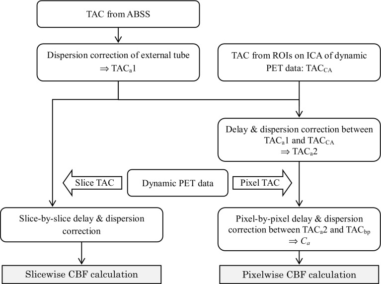
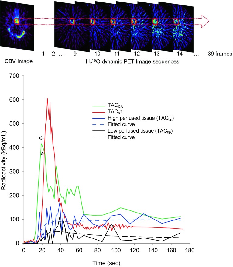
Dynamic data from each H2 15O PET scan were used for delay correction of the arterial input function at slice-by-slice and pixel-by-pixel level. In the pixel-by-pixel delay correction method, the time difference between the arterial blood sampling point and local brain tissue pixels was estimated in two steps (Fig. 1). First, the time-activity curves (TAC) from arterial blood sampling with external dispersion correction (TACa1) was adjusted to that of the cavernous part of ICA obtained from dynamic PET data (TACCA). The position of the region of interest (ROI) for the TACCA was determined using the CBV image (Fig. 2). The maximum count in the ROI of each frame was used for the TACCA. The delay time between the TACa1 and TACCA was estimated using the slope method except for a few cases whose TACs could not be adjusted by the slope method; the least squares fitting approach was applied in these cases [4, 9, 22]. For delay and dispersion correction of the TACa1, the same time constant estimated above was used and the TACa2 was obtained [22, 23].
Fig. 1.
In the slice-by-slice correction method, TACa1 is used for CBF calculation after slicewise delay correction and fixed dispersion (4 s). In the pixel-by-pixel correction method, TACa1 is adjusted to TACCA (=TACa2) and brain pixel TAC (TACbp) was used for delay and dispersion correction of TACa2. The standard method for delay estimation is slicelwise correction or a single delay correction for the whole brain (left flow)
Fig. 2.
Upper Scheme showing the region of interest (ROI) for ICA TAC and its application to the dynamic PET data. Bottom Representative TACs from arterial blood sampling (TACa1, red line), ROI peak value in the ICA region (TACCA, green line) and the regional pixel value in the high and low perfused brain tissue (TACbp, blue and black solid lines, respectively). Blue and black dotted lines (fitted curve) show a result of non-linear least squares fitting of the arterial input after delay and dispersion correction for each TACbp. The arrow shows the direction of delay correction to adjust the initial slope of TACa1 to TACCA. In cases of a long delay time, the difference between TACa1 and TACCA was greater than 10 s
Second, the delay time of tracer arrival at regional brain tissue from the ICA trunk was estimated for each pixel using the brain pixel TAC (TACbp) and the TACa2. The pixel delay time was determined using least-squares fitting for the initial 60 s of TACa2 and TACbp with a step size of 0.1 s [9], and a delay image was obtained from the pixelwise delay time estimation. As the delay and dispersion constants are very closely correlated [22, 23], the pixel delay time estimated from TACa2 and TACbp was also used as the dispersion time constant for the TACa2 correction to obtain the local input function. The local input function (C a), corrected for pixelwise delay and dispersion, was used in the subsequent image calculations.
Calculation of regional CBF and V0
The model for the 1-TCM can be represented by the following equation [6, 7],
| 1 |
where M e(t) (Bq/100 g) is the radioactivity in the brain tissue and C a(t) (Bq/mL) is the true arterial input function. K 1 (mL/100 g/min) and k 2 (1/min) are the rate constants for influx and outflux of the tracer, respectively [7]. K 1 apparently represents regional CBF. The equation is solved as
| 2 |
where ⊗ represents the convolution. Including the radioactivity in the intravascular spaces, total radioactivity in the brain is expressed as
| 3 |
where M(t) (Bq/100 g) is the regional PET count, and V 0 (mL/100 g) is the arterial-to-capillary vascular volume [7]. Here, K 1, k 2 and V 0 can be calculated from measured M(t) and C a(t) using the weighted method to reduce the image calculation time [6, 7, 12]. In brief, Eq. 3 can be integrated after weighting with three different weights of w i(t) (i = 1–3) as below:
| 4 |
Equation 5 is obtained by rearranging three equations of Eq. 4 to eliminate the V 0 term, where K 1 is cancelled, and various k 2 values can be estimated from the right-hand side ratio using the table look-up method.
| 5 |
The K 1 values can be estimated either from the numerator or denominator by substituting the k 2 values in Eq. 5. The same weighting functions of w 1(t) to w 3(t) were used as in the original papers [6, 7]. Finally, the parameter V 0 can be obtained from K 1 and k 2 using Eq. 4 [6].
Details of the slice-by-slice calculation method are described elsewhere [6, 7, 22, 23]. In brief, a single delay time estimated from the mean TAC of each slice of the brain was used in the calculation program based on Eqs. 4 and 5 with fixed dispersion of 4 s (Fig. 1). A MATLAB toolkit included in the EMMA (Extensible MATLAB Medical image Analysis: http://www.bic.mni.mcgill.ca/software/emma/) programs developed at the Montreal Neurological Institute (McGill University, Montreal, Canada) was modified and applied for the calculation of the weighted integration method. In the pixel-by-pixel calculation, pixelwise correction for delay and dispersion of the arterial input function was applied to measurement of CBF and V 0 (Fig. 1). The programs for the pixel-by-pixel were modified from the slice-by-slice calculation described above. An individual mask image to exclude radioactivity outside of the brain obtained from the average tissue activity image was applied to the dynamic PET data before CBF and V 0 calculation to reduce the calculation time. The final parametric PET images were smoothed using a Gaussian filter with a size of 6 mm.
Cerebral vascular reactivity (CVR) was calculated as the percentage change in CBF from images before and after the ACZ challenge test for both slice-by-slice (CVRs) and pixel-by-pixel (CVRp) delay correction.
Error analyses in CBF and V0 calculation
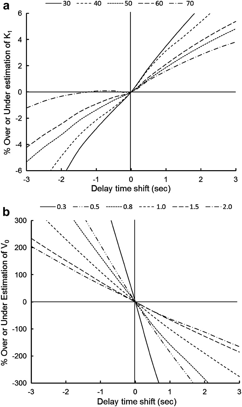
Error analyses were performed to investigate the biases of the CBF and V 0 estimations with simulated delay time shifts. Several small ROIs 10-mm in diameter, including about 30 voxels, were drawn on the brain cortex of parametric images for various values of CBF (30–70 mL/min/100 g) and V 0 (0.3–2.0 mL/100 g) to obtain tissue TACs from dynamic PET data. The arterial input function after the delay and dispersion correction for the brain tissue TAC (=C a) was shifted from −3 to 3 s in steps of 0.5 s in the analyses. Using these two TACs of tissue activity and shifted C a, CBF and V 0 were recalculated based on a 1-TCM. Percent changes from the original CBF and V 0 values were calculated and plotted to observe the effect of delay estimation errors on parametric values.
Statistical analysis
In the MCA territory, 30 circular ROIs 10 mm in diameter were set for each hemisphere. The same ROIs were applied to all parametric images of individual subjects. For statistical analysis, the SPSS ver. 18 (IBM Co., Armonk, NY, USA) was used. Repeated measures analysis of variance (ANOVA) with a post-hoc test by the Student–Newman–Keuls method was applied to analyze the difference in estimated hemodynamic parameters between ipsilateral and contralateral sides, as well as CBF and V 0 values before and after ACZ administration. CBF and V 0 values from the different delay correction methods were also compared. P < 0.05 was considered to be statistically significant. Correlation analyses were conducted among different PET parameters from this study to observe relationships as well as to confirm theoretical changes in cerebral hemodynamics.
Results
Representative TACs from arterial blood sampling with dispersion correction for the external tube (TACa1), maximum ROI values in the ICA region (TACCA), and one of the pixels in the brain tissue (TACbp) from both high and low perfused regions are given in Fig. 2. After TACa2 was estimated by delay and dispersion correction of TACa1, the true input function at each pixel level (C a) was obtained by delay and dispersion correction of TACa2. The result of curve fitting between C a and TACbp for CBF and V 0 calculation is also given in Fig. 2 (dotted lines).
There were no differences in physiological data before and after the ACZ injection except for the arterial O2 partial pressure (77.5 ± 9.4 vs. 86.5 ± 9.9 mmHg, P < 0.001). Mean values of hemodynamic parameters in the MCA region are given in Table 1. All parametric data showed significant differences between the two hemispheres; CBF, V0 and CMRO2 were significantly lower and CBV and OEF were significantly higher in the affected side compared with the contralateral hemisphere (P < 0.05). In the comparison between pixel-by-pixel and slice-by-slice delay correction methods, V 0 values were significantly greater with the slice-by-slice than with the pixel-by-pixel correction method both before and after ACZ administration; however, CBF from the different correction methods did not show significant differences in both conditions. CVR values were significantly smaller in the ipsilateral side than the contralateral side for both pixel-by-pixel and slice-by-slice delay correction, and the two methods provided very close values. The delay image showed a significantly longer mean delay time in the affected hemisphere compared to that in the contralateral side (2.81 ± 0.14 s vs. 2.66 ± 0.15 s, P < 0.05). The asymmetry indices for the average delay times of the ipsi- to the contra-lateral hemispheres were in the range of 1.00–1.13.
Table 1.
Hemodynamic parameters of 15O-PET study in patients
| Parameter | Ipsilateral | Contralateral | ||
|---|---|---|---|---|
| Slice-by-slice | Pixel-by-pixel | Slice-by-slice | Pixel-by-pixel | |
| CBFB (mL/100 g /min) | 45.1 ± 6.4* | 46.5 ± 7.3* | 50.6 ± 5.6 | 52.6 ± 6.8 |
| CBFA (mL/100 g /min) | 52.8 ± 7.4*$ | 54.2 ± 8.6*$ | 63.1 ± 5.5$ | 65.7 ± 5.6$ |
| Baseline V 0 (mL/100 g) | 2.54 ± 0.73*† | 1.37 ± 0.64*† | 3.08 ± 1.03† | 1.75 ± 0.72† |
| After ACZ V0 (mL/100 g) | 2.55 ± 0.87*† | 1.39 ± 0.69*† | 3.59 ± 0.76† | 2.13 ± 1.07† |
| CVR (%) | 17.4 ± 11.1* | 17.0 ± 12.3* | 25.5 ± 9.6 | 25.7 ± 10.5 |
| Delay (s) | 2.81 ± 0.14* | 2.66 ± 0.15 | ||
| CMRO2 (mL/100 g/min) | 2.87 ± 0.31* | 3.06 ± 0.32 | ||
| OEF (%) | 50.7 ± 4.8* | 45.9 ± 5.7 | ||
| CBV (mL/100 g) | 3.91 ± 0.70* | 3.59 ± 0.72 | ||
ACZ acetazolamide, CBF B baseline cerebral blood flow, CBF A cerebral blood flow after ACZ; CMRO 2 cerebral metabolic rate of oxygen, OEF oxygen extraction fraction, CBV cerebral blood volume
* P < 0.05 ipsi- vs. contra-lateral; † P < 0.05 slice-by-slice vs. pixel-by-pixel delay correction; $ P < 0.05 before and after ACZ
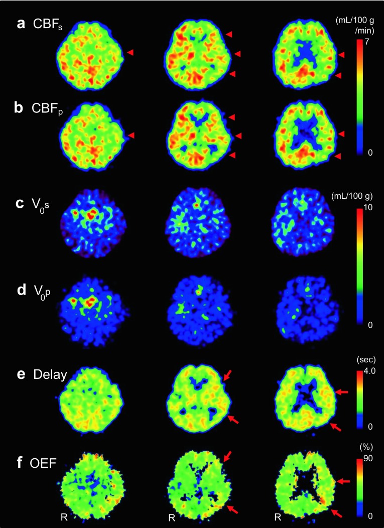
Parametric images of a representative case of left ICA stenosis are given in Fig. 3. CBF images with pixel-by-pixel delay correction (Fig. 3b) show similar cortical regional values to those from slice-by-slice delay correction (Fig. 3a). V 0 images show significantly different quantitative values in the whole brain between the two delay correction methods (Fig. 3c, d). The delay image (Fig. 3e) shows the laterality of tracer arrival to be slightly longer in the affected left side (arrows) than in the contralateral side. The OEF image shows an ipsilateral increase compared with the contralateral side (Fig. 3f).
Fig. 3.
Images from a representative case with left ICA stenosis (R at the bottom of each column shows right side of the patient): Baseline CBF images calculated by slice-by-slice a and pixel-by-pixel b delay correction show a CBF decrease in left MCA territory. Arrowheads indicate CBF decrease in the affected side. CBF values were very close between the two methods. Baseline V 0 images obtained by slice-by-slice c and pixel-by-pixel d delay correction show a significant difference in quantitative values between the two methods (2.08 vs. 1.27 mL/100 g in the global V 0 mean). Asymmetry indexes (% difference between the hemispheres) were 78 and 72% for slice-by-slice and pixel-by-pixel methods, respectively. A delay image e from the pixel-by-pixel method shows a longer delay time in the left hemisphere in accordance with the OEF elevation (f) (arrows)
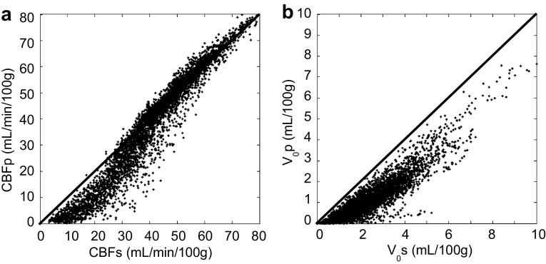
Figure 4 shows a pixelwise comparison between the two delay correction methods of pixel-by-pixel and slice-by-slice, in which CBF pixel values from the latter method were overestimated in the lower range although CBF values around 35 (mL/100 g/min) or higher showed a good correlation between the two methods. In contrast, V 0 pixel values from the slice-by-slice delay correction method were overestimated in the whole brain compared with the pixel-by-pixel correction.
Fig. 4.
Pixelwise comparison of baseline CBF a and V 0 b between the methods of slice-by-slice (CBFs and V 0s) and pixel-by-pixel (CBFp and V 0p) delay correction. Scatter plots were obtained from pixel values of a representative image slice
Figure 5 shows analyses of the effects of estimation error in the delay time correction on CBF and V 0 values (time-shift simulation of the arterial input function from the true input function). A negative time shift indicates a delayed tracer arrival compared to the true input function at the local brain region, and a positive shift represents an advanced tracer arrival. Both parameters showed greater estimation errors in the longer time shift from the true input function; however, the error range in CBF was significantly smaller than the estimation errors observed in V 0 calculation. Smaller parametric values tended to show greater errors in error estimation of delay time in both parameters.
Fig. 5.
Results from error analyses assessed for effects of delay time shift on CBF a and V 0 b values. A negative time shift assumes a delayed tracer arrival at the local brain region compared with the true input function, and a positive shift indicates an advanced tracer arrival. Different lines show various regional values of CBF (mL/min/100 g) and V 0 (mL/100 g) as given at the top of the graphs
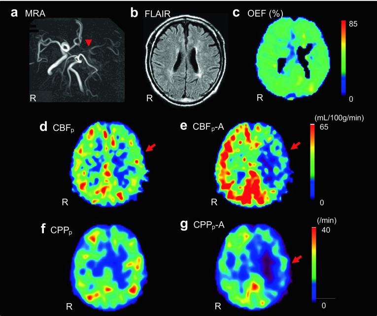
Figure 6 shows a representative case with left ICA occlusion, whose PET results significantly affected a treatment decision. Although the 15O-PET study showed a slight decrease in baseline CBF in the MCA territory (Fig. 6d), no significant OEF increase was observed in the affected region (Fig. 6c). The ACZ challenge test showed a significant decrease in CVR (Fig. 6e), but baseline CBF did not decrease significantly, and the results indicated stage I hemodynamic impairment. The cerebral perfusion pressure (CPP) image calculated from CBF/V 0 showed a significant decrease after ACZ administration in left MCA territory (Fig. 6f, g), which indicated significant hemodynamic impairment. The patient underwent EC–IC bypass surgery because of the PET results and his symptoms of TIA.
Fig. 6.
A representative case from this study. The patient had left ICA occlusion on MRA (a). Arrowhead shows the occlusion of ICA. MRI FLAIR image showed no significant ischemic region in the MCA territory (b). Although OEF image showed no significant increase in the left cerebral hemisphere (c), baseline CBFp showed a tendency of decrease in the MCA territory (d). ACZ challenge test showed significant decrease in CBFp (e) and CPPp (f baseline, g after ACZ) in the affected region. The study indicated significant hemodynamic impairment because of the significant decrease in CVR and CPP, and the patient underwent EC–IC bypass surgery. CBFp-A and CPPp-A means pixel-by-pixel calculated CBF and CPP after ACZ. R on each panel represents right side of the patient. Red arrows show affected side of MCA territory
Figure 7 shows the relationships of hemodynamic parameters obtained from this study. Although CBF did not show a correlation with delay time, CVRp and OEF had significant negative (a: r = −0.37) and positive (b: r = 0.37) correlations with delay time, respectively (P < 0.05). The difference of delay time between the contralateral to the ipsilateral hemisphere showed a significant correlation with CVRp as well (c: r = − 0.47, P < 0.05). If we calculate cerebral perfusion pressure (CPP) with an equation of CBF/V 0, CPPp showed a good correlation with CBF linearly (r = 0.39, P < 0.05) or rather better in a logarithmic function (d: r = 0.43, P < 0.01). In contrast, V 0 and CBV did not show a significant correlation (r = 0.24).
Fig. 7.
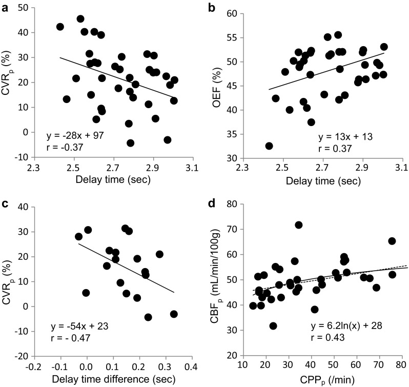
Different hemodynamic parameters were plotted from pixel-by-pixel delay estimation. The best fit regression line for correlation analysis was selected for each graph. a Delay time vs. CVRp, (P < 0.05), b Delay vs. OEF, (P < 0.05), c Delay time difference between contra- and ipsi-lateral hemisphere vs. CVRp, (P < 0.05), d arterial cerebral perfusion pressure (CPPp) obtained from CBF/V0p vs. CBFp (P < 0.01). Dashed line shows linear regression (y = 0.15x + 43.7, r = 0.39, P < 0.05)
Discussion
In the present study, a pixel-by-pixel delay time estimation for accurate correction was employed to calculate precise CBF and V 0 images. The mean values of cortical CBF were not significantly different between the methods and the scatter plots showed a good correlation in the moderate to high perfusion range although the slice-by-slice correction method overestimated CBF values in the hypoperfused regions. Since the brain hypoperfused regions should have a longer delay time shift and errors were greater compared with the normal and high blood flow regions, CBF in those regions would have been overestimated in the slice-by-slice method (Figs. 5, 7). This result is important in a clinical setting because the hypoperfused regions are the target for hemodynamics evaluation and OEF increase due to CBF reduction should be the high risk region of hemodynamic infarction [24]. The ACZ challenge test with the perfusion SPECT or PET study is also useful for evaluating hemodynamic impairment in CVD patients, and it is used as an indication for EC–IC bypass surgery and other neurosurgical treatments in Japan [25, 26]. In both studies, precise measurement of CBF is very important.
V 0 values, however, showed significant difference between the two methods in the whole V 0 range of the brain because a slight shift of delay time estimation results in significant calculation errors [7]. The pixelwise delay for each brain location from TACa2 was estimated in a narrow range of 0–4 s, which reduced the image calculation time compared with direct pixel-by-pixel delay estimation from the TACa1, and provided an accurate delay time for V 0 calculation. This delay of tracer arrival time from the ICA was almost identical to that in a previous study [9]. Direct delay estimation of TACbp from TACa1 provided a greater range of delay between −5 s to more than 10 s depending on sclerotic and stenotic changes in the arteries of the blood sampling site and the local brain compared with our two-step correction method. The two-step method can avoid the effect of sclerotic changes in the brachial artery by adjusting TACa1 to TACCA at first. Furthermore, the advantage of the pixel-by-pixel delay estimation is that it produces a delay time image which is a similar parameter to time-to-peak or arterial transit-time in MR perfusion studies, that would be beneficial information for the assessment of hemodynamic status in CVD patients. Because the delay time was correlated with OEF and CVR (Fig. 7), it may be able to estimate OEF elevation and CVR reduction without a 15O2 scan or the ACZ challenge test. If the image derived input function method with 15O-water PET is established, the delay image might be beneficial as one of the screening tools.
Previous studies reported that CBF values are sensitive to errors in delay time estimation, where a positive delay time shift shows overestimation and a negative shift underestimates CBF values [7, 9, 27]. We also observed similar estimation errors from the error analyses (Fig. 5a). The percent change in CBF values of less than 7% in the range of − 2 to 2 s shift, which is consistent with the report by Iida et al. [9], seems small enough and acceptable. In the present study, the difference of CBF values between slice-by-slice and pixel-by-pixel delay correction was less than 4% in the cortical region, and the difference was not significant in statistical analysis. However, significantly longer delay times in the severely affected brain regions may induce significant errors in the slice-by-slice correction. Our two-step method with the positive delay time shift (0–4 s) seems more robust in CBF measurement with negligible errors compared to the slice-by-slice direct correction method.
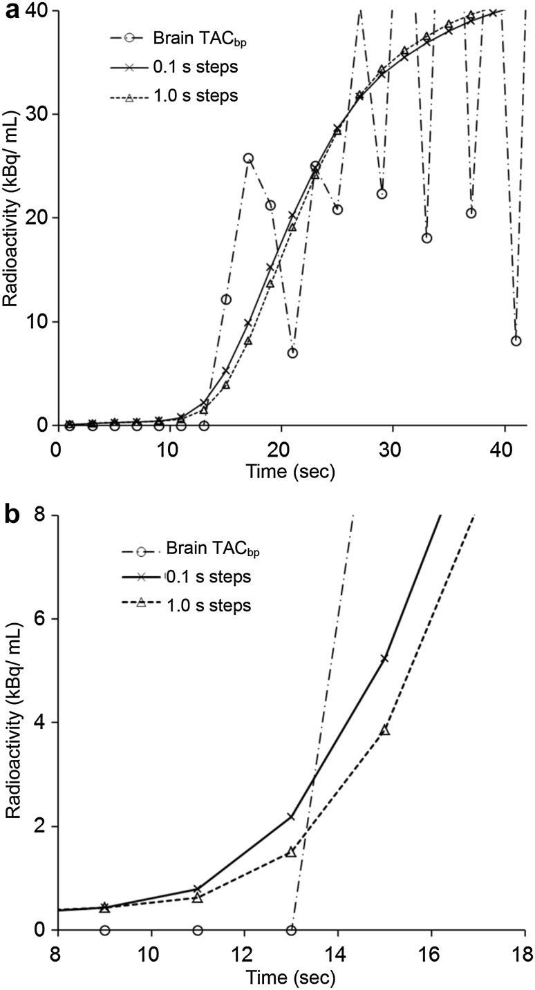
In contrast, V 0 values seem to be more vulnerable to errors in delay estimation than in CBF [7]. The error range is not negligible because only a 1 s time shift may cause 50–200% difference in the V 0 range of 0.5–2.0 (mL/100 g) (Fig. 5b). The significant overestimation of V 0 values with a small error of delay estimation in the slice-by-slice method may have a severe effect in a clinical setting, which confirms the necessity of pixel-by-pixel delay correction. The V 0 apparently reflects the arterial-to-capillary blood volume, which is different from CBV including venous volume [7, 11, 28]. To evaluate cerebral perfusion pressure (CPP) from PET parameters, CBF/V 0 would be more appropriate than CBF/CBV values [14, 28], and images with precise regional values of V 0 offer beneficial information for the assessment of hemodynamics of CVD. The high temporal resolution (0.1 s) for delay time estimation between TACa2 and Cbp in the present study is preferable for this precise estimation of PET parameters because different time steps of 0.1 and 1.0 s for delay estimation showed differences in delay time as well as V 0 values (Fig. 8). The residuals for the fittings with 1.0, 0.1 and 0.01 s steps were almost the same and CBF values did not show differences; however, the 1.0 s step delay time estimation provided significantly different V 0 values not only in the affected side, but also in the contralateral side compared with those of 0.1 or 0.01 s steps (data not shown). Because the different time steps of 0.1 and 0.01 s did not lead to differences in the results of delay, CBF and V 0, we decided to use 0.1 s steps for delay time estimation. The calculation time of the delay estimation was not much affected by difference in the temporal resolution (step size). However, least-squares fitting for CBF and V 0 calculation using Eq. 3 is still time consuming even after recent improvements in computer power. The weighted integration method reduces calculation time significantly as previously reported [6, 7, 29].
Fig. 8.
Representative curves of TACbp and TACa2 after fitting using the least-squares method for delay estimation (a) and zoom of the graph between 8 and 18 s (b). 0.1 s steps showed a better fitting curve (solid line) than 1.0 s steps (dotted line) and delay times from these fittings were estimated to be 1.6 and 2.0 s for 0.1 and 1.0 s steps, respectively. These delay times estimated quantitative values of this voxel to be 34.1 and 33.5 (mL/100 g/min) for CBF and 0.9 and 1.4 (mL/100 g) for V 0, respectively. The statistical analysis showed that CBFp was not different in cortical values, but V0p was significantly different for both hemispheres
Regional CVRp, which reflects the vasodilatory capacity, showed a significant correlation with delay time and asymmetry of delay (Fig. 7a, c). The negative correlation represents a longer tracer arrival time in the severely affected region, which is consistent with impaired hemodynamic change in the area. Although the means of delay time in the ipsi- and contra-lateral hemispheres showed only 0.15 s difference (Table 1), a mean value is often blurred by the mixing of significant and insignificant results, and the statistical analysis showed that the difference was significant. Parameters of oxygen metabolism measured by 15O-gas PET could be compared with the new parameters in the present study because this is a retrospective study to propose the better analyses of patients’ hemodynamic conditions using 15O-water PET. OEF showed a significant correlation with delay time (Fig. 7b), indicating that delay time is closely correlated with hemodynamic impairment. The lower range of CPP showed a positive correlation with CBF although CBF tended to reach a plateau value in higher CPP. This correlation is also consistent with the theory of hemodynamic changes [14, 15, 30], as we previously reported the importance of precise estimation of V0 for the CPP evaluation [28].
In the present study, the pixel-by-pixel calculation estimated V 0 in the contralateral hemisphere to be about 49% of CBV, which is close to the values in the previous reports (about 20–40%) [31, 32]. However, the slice-by-slice delay correction estimated contralateral V 0 to be about 87% of CBV, which is greater than our previous studies showing V 0 values of less than 60% of CBV [11, 28]. Although the difference in the initial frame time (5 s in the previous studies) may have provided greater V 0 values in the slice-by-slice calculation method, the initial slope at tracer arrival was estimated better in 2-sec than in 5-s frames, especially when obtaining the TACCA. The coefficient of variation (COV) values were calculated from ROIs drawn on each cerebral hemisphere of the patients. CBF images showed no difference in COV (0.18 ± 0.02 for both calculation methods), and V 0 images showed 0.37 ± 0.07 and 0.50 ± 0.11 for the slice-by-slice and pixel-by-pixel methods, respectively. This result indicates that the V 0 image was noisier in the latter method than in the former one, and improvement of image quality may be needed for V 0 evaluation.
Since the patients enrolled in this study had only minor symptoms and half of them were asymptomatic, we might have seen different results from severely affected cerebral circulation in symptomatic patients. However, a tendency of hemodynamic impairment in the chronic phase of CVD was observed in the present study, suggesting that this method for precise estimation of delay time correction would be ideal for the assessment of CVD caused by stenoocclusive lesions in the major cerebral arteries. Baseline V 0 tended to show smaller values in the ipsilateral side compared with the contralateral side (Table 1), and the result was similar to the previous works [28, 33]. In the chronic phase of CVD, the arteriole-to-capillary part of vessels may not necessarily show vasodilatory change, and increase in CBV is assumed to be caused mainly by increase in venous volume. In the present study, only a few cases were in the stage of misery perfusion assessed by a significant OEF increase, and these patients also did not show significant increase in ipsilateral V 0. Microvascular impairment in cerebral ischemic change may cause capillary collapse in the chronic phase of CVD [34].
Conclusion
The precise estimation of hemodynamic parameters such as CBF and V 0 using the new method should be ideal and beneficial for clinical use. Pixel-by-pixel delay estimation also provides a new image of delay time that should provide useful information for the clinical assessment of CVD.
Acknowledgements
The authors thank the staff of the Biomedical Imaging Research Center and doctors in the Department of Neurosurgery, University of Fukui for technical and clinical support. This study was partly funded by a Grant-in-Aid for Scientific Research from the Japan Society for the Promotion of Science (15K15453).
Compliance with ethical standards
Financial support
This study was partly funded by a Grant-in-Aid for Scientific Research from the Japan Society for the Promotion of Science (15K15453).
References
- 1.Frackowiak RS, Lenzi GL, Jones T, Heather JD. Quantitative measurement of regional cerebral blood flow and oxygen metabolism in man using 15O and positron emission tomography: theory, procedure, and normal values. J Comput Assist Tomogr. 1980;4:727–736. doi: 10.1097/00004728-198012000-00001. [DOI] [PubMed] [Google Scholar]
- 2.Herscovitch P, Markham J, Raichle ME. Brain blood flow measured with intravenous H215O. I. Theory and error analysis. J Nucl Med. 1983;24:782–789. [PubMed] [Google Scholar]
- 3.Raichle ME, Martin WRW, Herscovitch P, Mintun MA, Markham J. Brain blood flow measured with intravenous H215O: II. Implementation and validation. J Nucl Med. 1983;24:790–798. [PubMed] [Google Scholar]
- 4.Kanno I, Iida H, Miura S, Murakami M, Takahashi K, Sasaki H, et al. A system for cerebral blood flow measurement using an H215O autoradiographic method and positron emission tomography. J Cereb Blood Flow Metab. 1987;7:143–153. doi: 10.1038/jcbfm.1987.37. [DOI] [PubMed] [Google Scholar]
- 5.Gambhir SS, Huang SC, Hawkins RA, Phelps ME. A study of the single compartment tracer kinetic model for the measurement of local cerebral blood flow using 15O water and positron emission tomography. J Cereb Blood Flow Metab. 1987;7:13–20. doi: 10.1038/jcbfm.1987.3. [DOI] [PubMed] [Google Scholar]
- 6.Ohta S, Meyer E, Thompson CJ, Gjedde A. Oxygen consumption of the living human brain measured after a single inhalation of positron emitting oxygen. J Cereb Blood Flow Metab. 1992;12:179–192. doi: 10.1038/jcbfm.1992.28. [DOI] [PubMed] [Google Scholar]
- 7.Ohta S, Meyer E, Fujita H, Reutens DC, Evans A, Gjedde A. Cerebral [15O]water clearance in humans determined by PET: I. Theory and normal values. J Cereb Blood Flow Metab. 1996;16:765–780. doi: 10.1097/00004647-199609000-00002. [DOI] [PubMed] [Google Scholar]
- 8.Toussaint PJ, Meyer E. A sensitivity analysis of model parameters in dynamic blood flow studies using H215O and PET. In: Myers R, Cunningham V, Bailey D, Jones T, editors. Quantification of brain function using PET. San Diego: Academic Press; 1996. pp. 196–200. [Google Scholar]
- 9.Iida H, Higano S, Tomura N, Shishido F, Kanno I, Miura S, et al. Evaluation of regional differences of tracer appearance time in cerebral tissues using [15O]water and dynamic positron emission tomography. J Cereb Blood Flow Metab. 1988;8:285–288. doi: 10.1038/jcbfm.1988.60. [DOI] [PubMed] [Google Scholar]
- 10.Iida H, Kanno I, Miura S, Murakami M, Takahashi K, Uemura K. A determination of the regional brain/blood partition coefficient of water using dynamic positron emission tomography. J Cereb Blood Flow Metab. 1989;9:874–885. doi: 10.1038/jcbfm.1989.121. [DOI] [PubMed] [Google Scholar]
- 11.Okazawa H, Yamauchi H, Sugimoto K, Takahashi M, Toyoda H, Kishibe Y, et al. Quantitative comparison of the bolus and steady-state methods for measurement of cerebral perfusion and oxygen metabolism: Positron emission tomography study using15O-Gas and Water. J Cereb Blood Flow Metab. 2001;21:793–803. doi: 10.1097/00004647-200107000-00004. [DOI] [PubMed] [Google Scholar]
- 12.Okazawa H, Vafaee M. Effect of vascular radioactivity on regional values of cerebral blood flow evaluation of methods for H215O PET to distinguish cerebral perfusion from blood volume. J Nucl Med. 2001;42:1032–1039. [PubMed] [Google Scholar]
- 13.Iida H, Law I, Pakkenberg B, Krarup-Hansen A, Eberl S, Holm S, et al. Quantitation of regional cerebral blood flow corrected for partial volume effect using O-15 water and PET: I. Theory, error analysis, and stereologic comparison. J Cereb Blood Flow Metab. 2000;20:1237–1251. doi: 10.1097/00004647-200008000-00009. [DOI] [PubMed] [Google Scholar]
- 14.Okazawa H, Kudo T. Clinical impact of hemodynamic parameter measurement for cerebrovascular disease using positron emission tomography and 15O-labeled tracers. Ann Nucl Med. 2009;23:217–227. doi: 10.1007/s12149-009-0235-7. [DOI] [PubMed] [Google Scholar]
- 15.Powers WJ, Zazulia AR. PET in cerebrovascular disease. PET Clin. 2010;5(1):83106. doi: 10.1016/j.cpet.2009.12.007. [DOI] [PMC free article] [PubMed] [Google Scholar]
- 16.DeGrado TR, Turkington TG, Williams JJ, Stearns CW, Hoffman JM, Coleman RE. Performance characteristics of a whole-body PET scanner. J Nucl Med. 1994;35:1398–1306. [PubMed] [Google Scholar]
- 17.Isozaki M, Kiyono Y, Arai Y, Kudo T, Mori T, Maruyama R, et al. Feasibility of 62Cu-ATSM PET for evaluation of brain ischemia and misery perfusion in patients with cerebrovascular disease. Eur J Nucl Med Mol Imaging. 2011;38:1075–1082. doi: 10.1007/s00259-011-1734-z. [DOI] [PubMed] [Google Scholar]
- 18.Okazawa H, Tsuchida T, Kobayashi M, Arai Y, Pagani M, Isozaki M, et al. Can reductions in baseline CBF and vasoreactivity detect misery perfusion in chronic cerebrovascular disease? Eur J Nucl Med Mol Imaging. 2007;34:121–129. doi: 10.1007/s00259-006-0192-5. [DOI] [PubMed] [Google Scholar]
- 19.Mintun MA, Raichle ME, Martin WRW, Herscovitch P. Brain oxygen utilization measured with 0–15 radiotracers and positron emission tomography. J Nucl Med. 1984;25:177–187. [PubMed] [Google Scholar]
- 20.Okazawa H, Kishibe Y, Sugimoto K, Takahashi M, Yamauchi H. Delay and dispersion correction for a new coincidential radioactivity detector, pico-count, in quantitative PET studies. In: Senda M, Kimura Y, Herscovitch P, editors. Brain imaging using PET. San Diego, CA: Academic Press; 2002. pp. 15–21. [Google Scholar]
- 21.Vafaee M, Murase K, Gjedde A, Meyer E. Dispersion correction for automatic sampling of O-15-labeled H2O and red blood cells. In: Myers R, Cunningham V, Bailey D, Jones T, editors. Quantification of brain function using PET. San Diego: Academic Press; 1996. pp. 72–75. [Google Scholar]
- 22.Meyer E. Simultaneous correction for tracer arrival delay and dispersion in CBF measurements by the H215O autoradiographic method and dynamic PET. J Nucl Med. 1989;30:1069–1078. [PubMed] [Google Scholar]
- 23.Iida H, Kanno I, Miura S, Murakami M, Takahashi K, Uemura K. Error analysis of a quantitative cerebral blood flow measurement using H215O autoradiography and positron emission tomography, with respect to the dispersion of the input function. J Cereb Blood Flow Metab. 1986;6:536–545. doi: 10.1038/jcbfm.1986.99. [DOI] [PubMed] [Google Scholar]
- 24.Yamauchi H, Higashi T, Kagawa S, Nishii R, Kudo T, Sugimoto K, et al. Is misery perfusion still a predictor of stroke in symptomatic major cerebral artery disease? Brain. 2012;135:2515–2526. doi: 10.1093/brain/aws131. [DOI] [PubMed] [Google Scholar]
- 25.Ogasawara K, Ogawa A, Yoshimoto T. Cerebrovascular reactivity to acetazolamide and outcome in patients with symptomatic internal carotid or middle cerebral artery occlusion: a xenon-133 single-photon emission computed tomography study. Stroke. 2002;33:1857–1862. doi: 10.1161/01.STR.0000019511.81583.A8. [DOI] [PubMed] [Google Scholar]
- 26.Kuroda S, Houkin K, Kamiyama H, Mitsumori K, Iwasaki Y, Abe H. Long-term prognosis of medically treated patients with internal carotid or middle cerebral artery occlusion: can acetazolamide test predict it? Stroke. 2001;32:2110–2116. doi: 10.1161/hs0901.095692. [DOI] [PubMed] [Google Scholar]
- 27.Kudomi N, Maeda Y, Sasakawa Y, Monden T, Yamamoto Y, Kawai N, et al. Imaging of the appearance time of cerebral blood using [15O]H2O PET for the computation of correct CBF. Eur J Nucl Med Mol Imaging Res. 2013;3:41. doi: 10.1186/2191-219X-3-41. [DOI] [PMC free article] [PubMed] [Google Scholar]
- 28.Okazawa H, Yamauchi H, Toyoda H, Sugimoto K, Fujibayashi Y, Yonekura Y. Relationship between vasodilatation and cerebral blood flow increase in impaired hemodynamics: a PET study with the acetazolamide test in cerebrovascular disease. J Nucl Med. 2003;44:1875–1883. [PubMed] [Google Scholar]
- 29.Ito H, Iida H, Bloomfield PM, Murakami M, Inugami A, Kanno I, et al. Rapid calculation of regional cerebral blood flow and distribution volume using iodine-123-iodo- amphetamine and dynamic SPECT. J Nucl Med. 1995;36:531–536. [PubMed] [Google Scholar]
- 30.Powers WJ. Cerebral hemodynamics in ischemic cerebrovascular disease. Ann Neurol. 1991;29:231–240. doi: 10.1002/ana.410290302. [DOI] [PubMed] [Google Scholar]
- 31.Ito H, Kanno I, Iida H, Hatazawa J, Shimosegawa E, Tamura H, Okudera T. Arterial fraction of cerebral blood volume in humans measured by positron emission tomography. Ann Nucl Med. 2001;15:111–116. doi: 10.1007/BF02988600. [DOI] [PubMed] [Google Scholar]
- 32.Mellander S, Johansson B. Control of resistance, exchange, and capacitance functions in the peripheral circulation. Pharmacol Rev. 1968;20:117–196. [PubMed] [Google Scholar]
- 33.Okazawa H, Yamauchi H, Sugimoto K, Takahashi M. Differences of vasodilatory capacity and changes in cerebral blood flow induced by acetazolamide in patients with cerebrovascular disease. J Nucl Med. 2003;44:1371–1378. [PubMed] [Google Scholar]
- 34.Taylor ZJ, Hui ES, Watson AN, et al. Microvascular basis for growth of small infarcts following occlusion of single penetrating arterioles in mouse cortex. J Cereb Blood Flow Metab. 2016;36:1357–1373. doi: 10.1177/0271678X15608388. [DOI] [PMC free article] [PubMed] [Google Scholar]


