Abstract
For applications of metal–organic frameworks (MOFs) such as gas storage and separation, flexibility is often seen as a parameter that can tune material performance. In this work we aim to determine the optimal flexibility for the shape selective separation of similarly sized molecules (e.g., Xe/Kr mixtures). To obtain systematic insight into how the flexibility impacts this type of separation, we develop a simple analytical model that predicts a material’s Henry regime adsorption and selectivity as a function of flexibility. We elucidate the complex dependence of selectivity on a framework’s intrinsic flexibility whereby performance is either improved or reduced with increasing flexibility, depending on the material’s pore size characteristics. However, the selectivity of a material with the pore size and chemistry that already maximizes selectivity in the rigid approximation is continuously diminished with increasing flexibility, demonstrating that the globally optimal separation exists within an entirely rigid pore. Molecular simulations show that our simple model predicts performance trends that are observed when screening the adsorption behavior of flexible MOFs. These flexible simulations provide better agreement with experimental adsorption data in a high-performance material that is not captured when modeling this framework as rigid, an approximation typically made in high-throughput screening studies. We conclude that, for shape selective adsorption applications, the globally optimal material will have the optimal pore size/chemistry and minimal intrinsic flexibility even though other nonoptimal materials’ selectivity can actually be improved by flexibility. Equally important, we find that flexible simulations can be critical for correctly modeling adsorption in these types of systems.
Introduction
Metal–organic frameworks (MOFs) have garnered significant attention in the scientific community due to their potential applications ranging from gas storage and separations to catalysis and sensors.1−6 The diversity of applications for which MOFs are currently being investigated arises primarily from their highly tunable chemical and geometric properties since the combinatorics of their nodal composition, consisting of secondary building units (SBUs) and ligands, leads to an enormous number of possible structures.7 An interesting consequence of such structural diversity is that the flexibility of these materials can be exploited in various ways to yield improved performance in a variety of applications.8 Focusing on gas storage and separations, flexibility has been experimentally and computationally examined in the contexts of breathing,9−11 swelling,12 rotatable and flexible linkers,13,14 shape memory,15 complex lattice deformation,16 subnetwork displacement,17 negative gas adsorption,18,19 and its strong influence on diffusion,20 all with the ultimate goal of exploiting these phenomena to obtain desirable adsorption properties. Such breadth presents interesting challenges and opportunities for experimental and computational characterization of flexibility in MOFs and for determination of how it can be utilized for the design of better gas adsorbents.
MOFs with dynamic constituents (i.e., rotatable and flexible ligands)13 have pore spaces that can change in size and/or shape, while the unit cell volume and shape remains constant. A natural question that arises is whether this phenomenon can be optimized for specific applications in gas separations, and our work highlights how controlling this intrinsic flexibility of MOFs can optimize these materials for shape selective adsorption. An example of such an application is the separation of Xe/Kr mixtures where the most selective materials have a pore size and shape commensurate with the adsorbates,21 and thus we illustrate our findings in the context of the widely studied Xe/Kr separations.22,23
To study the effect of intrinsic flexibility on the separation of tight fitting molecules, we have developed a simple model that allows us to compute the selectivity in the Henry regime as a function of the flexibility of a material. Our model quantitatively and systematically demonstrates that intrinsic flexibility can either increase or decrease selectivity for a given material based on its pore size characteristics. However, an interesting consequence will follow: Achieving the globally optimal separation performance necessitates not only having a material with the ideal pore size and chemistry but also finding materials that simultaneously minimize intrinsic flexibility. Next we compare these results to Xe/Kr adsorption data obtained from screening the CoRE MOF database24 when each structure’s flexibility is modeled via a classical force field (FF) recently used in the literature.25 It is important to note that when high-throughput computational studies are employed to elucidate stucture–property relationships,26−29 they are almost exclusively performed using the rigid structure approximation (see details of ref (30) for the only exception to our knowledge). This approximation is considered a safe assumption when thermodynamic fluctuations are assumed to average out the framework atoms’ locations to their initial values, and so intrinsic flexibility is assumed to have no effect. However, by relaxing this approximation and using flexible simulations to screen a database of MOFs, we observe that flexibility has the same impact on adsorption behavior trends as shown by the analytical model. We then select several MOFs from the screening to study in further detail the effect of flexibility on each material’s performance in Xe/Kr separations and finally show that flexibility is necessary to yield better agreement with experimental adsorption data of a high performance MOF system known as SBMOF-1.23 Thus, we not only quantitatively and systematically demonstrate the impacts of flexibility on shape selective adsorption through models and simulations but also are able to answer the more fundamental question of whether controlling intrinsic flexibility can optimize material performance in this type of separation application.
Methods: Analytical Model
The effects of intrinsic flexibility in MOFs on Henry regime adsorption are elucidated by an analytical model of a flexible pore and direct simulations of flexible MOF materials. The details of the direct simulations are explained in the Methods: Direct Simulations section. For our analytical model, we construct a spherical pore of radius Rp consisting of a wall of carbon atoms. The visualization of this model is presented in Figure 1. A continuum approximation31 is invoked such that an adsorbate does not interact with discrete atomic centers but rather with a uniform surface density of atoms, η = 1 atom /(π × 1.2 Å2). This surface density is chosen to be slightly higher than that of graphene since adsorbates can interact with atoms beyond the pore wall in real MOF materials. This approximation will permit an integrable expression for the Henry coefficient, or the measure of a material’s affinity for an adsorbate in the limit of infinite dilution.32
Figure 1.
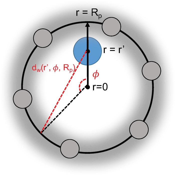
Visualization of a cross-section of the spherical pore model. The blue circle represents the adsorbate, and the gray spheres represent the pore wall carbon atoms whose interaction energies are “smeared” across the surface of the sphere with uniform density η. Due to the spherical symmetry, the total adsorption energy of an adsorbate at a given location r′ is simply an integral over the azimuth angle ϕ.
The adsorption energy of one adsorbate within the spherical pore is dependent only on the r coordinate due to spherical symmetry, as shown in Figure 1. Determination of this energy requires an integration of the host–adsorbate interaction across the pore surface, which in turn requires an expression for the distance between the adsorbate and any point on the surface, given by dw in eq 1:
| 1 |
When the interactions between the adsorbate and the pore wall are computed by a pairwise Lennard-Jones potential and smeared across the entire surface of the sphere rather than computed by discrete pairwise distances (as is the case in a direct simulation), the total adsorption energy takes the form of the integral in eq 2:
 |
2 |
where ϵij is the depth of the potential energy well and σij is the distance between the adsorbate and the wall at which the potential energy is zero. Using this expression for the adsorbate interaction energy, we can now calculate the Henry coefficient, which is often computed in simulations via the expectation value in eq 3:32
| 3 |
where β is (kBT)−1 and U+ is the total interaction energy of a randomly inserted ghost adsorbate. This expectation value can be rewritten as an integral over the pore volume by substitution of eq 2 for U+. The resulting eq 4 yields an integrable formula for the rigid pore Henry coefficient (KH,r) for a given radius Rp with spherical volume Vp:
| 4 |
Next, flexibility is introduced into the model by allowing Rp to change according to a Gaussian distribution. Now the flexible Henry coefficient (KH,f) is a function of the mean pore radius, ⟨Rp⟩, and the width of the Gaussian distribution of the radius, σp, as shown in eq 5:
| 5 |
The pore radius is bounded between Rmin and Rmax. Note that in the limiting case as σp approaches 0, the Gaussian distribution becomes a delta function, δ(⟨Rp⟩), and we recover the rigid pore approximation such that KH,f(⟨Rp⟩, 0) = KH,r(⟨Rp⟩). Hence the KH,f can be calculated over a range of average pore radii and distribution widths to demonstrate how the Henry coefficient depends on both the average size and strength of fluctuations inside a flexible pore. KH,f is calculated for both Xe and Kr (KH,fXe and KH,f, respectively) and the infinite dilution selectivity of the flexible model, Sf follows as the ratio of these two quantities in eq 6. The selectivity of the rigid model is just the ratio of the rigid Henry coefficients in eq 7:
| 6 |
| 7 |
Methods: Direct Simulations
In addition to the analytical model, direct simulations are employed using various computational techniques to demonstrate the effects of intrinsic flexibility on the Henry regime adsorption properties in MOFs. Ideally one would like to exclusively use ab initio calculations to describe such flexibility, but these are prohibitively expensive for large systems and long simulation times that are required to obtain sufficiently accurate results for these materials. Therefore, we rely on force-field-based molecular simulations and corroborate their performance with ab initio methods on a computationally feasible system. We elaborate the details of these simulation techniques starting with the description of the force fields used for classical molecular dynamics (MD) simulations of flexible materials, followed by a description of ab initio MD based on density functional theory (DFT). Finally we describe how the Henry coefficients are evaluated in these flexible materials as well as the calculation of geometric properties which are necessary to evaluate how the pore sizes change in MOFs between the rigid approximation and flexible simulations.
Force Field Computed Framework Dynamics
There exists a large diversity of metal–ligand chemistry in the CoRE MOF database24 (here we only study the materials for which density derived electrostatic and chemical, or DDEC, charges33 have been obtained), the entirety of which cannot be described by any single classical force field (Dreiding,34 UFF,35 BTW,36 UFF4MOF,37 etc.). In order to treat all materials on equal footing, we utilize the universal force field (UFF) for all framework bonded potentials except for the coordination bonds between metals and organic species. For bond and angle potentials that are centered on the metal ions, the equilibrium harmonic bond length and equilibrium harmoic angle are modified to the crystallographic values read from the structure file.25 This approximation is quite useful in that it allows us to simulate framework dynamics in the canonical ensemble, i.e., constant number of particles, volume, and temperature (NVT), for a vast majority of the CoRE MOF structures without significant unphysical distortions in the framework resulting from poor fits to UFF geometries. In a previous work we have demonstrated that this approximation is even sufficient to capture bulk moduli trends as calculated by DFT in various MOFs.25 This force field is hereon referred to as UFF-fix-metal (UFF-FM), and details on its implementation are presented in the SI.
To benchmark our classically generated dynamics using the UFF-FM approximation, we additionally performed an in-depth investigation of framework dynamics for one particular MOF, known as SBMOF-138 with reference code KAXQIL in the Cambridge Structural Database (CSD) that displays excellent Xe selectivity.23 We implement an additional classical force field which models metal–ligand coordination solely through Lennard-Jones interactions and electrostatics whereby dummy cation beads serve to delocalize the charge of the metal ion and preserve the octahedral geometry of the Ca2+ ions in the framework. While the model was originally developed to simulate solvation of cations,39 recent work has illustrated this model’s applicability in simulating MOF dynamics and deformation.16 All potentials other than the metal–ligand interactions were modeled with standard UFF potentials, and the model is hereon referred to as the UFF-cationic-dummy-model (UFF-CDM) with additional implementation details provided in the SI.
For generating an ensemble of structures from a MD run over which the Henry coefficient can be computed, each CoRE MOF from ref (24) was simulated with UFF-FM in the NVT ensemble using the open source LAMMPS software package (http://lammps.sandia.gov).40 The Nose–Hoover thermostat was used with a temperature of 298 K, and the structure was equilibrated for 30 ps, followed by a production run of 30 ps. During the production run, a framework configuration was saved every ps to give a total of 30 snapshots upon which the Henry coefficients could be calculated via the ensemble average in eq 3. Justification for the number of snapshots necessary is elaborated in the Porosity Characterization section. The same MD methods were used to simulate SBMOF-1 with UFF-CDM. Charges for UFF-FM simulations were taken from ref (24), while charges for UFF-CDM were derived from electronic structure calculations (see the subsequent section) and calculated according to the procedure discussed in the SI. Each MOF was simulated with periodic boundary conditions, and a cutoff radius of 12.5 Å was imposed for nonbonded interactions. Supercells were generated such that the perpendicular components of the cell vectors were at least two times the cutoff radius.
Ab Initio Computed Framework Dynamics
All DFT calculations have been performed using the CP2K code, which uses a mixed Gaussian/plane-wave basis set.41,42 We employed double-ζ polarization quality Gaussian basis sets43 and a 400 Ry plane-wave cutoff for the auxiliary grid, in conjunction with the Goedecker–Teter–Hutter pseudopotentials.44,45 All DFT calculations, including single point energies, geometry/cell optimizations, and ab initio molecular dynamics simulations (AIMD), were performed using the PBE functional,46 with Grimme’s D3 van der Waals correction (PBE+D3).47 This method was shown to give very good agreement with experimental structural data on several MOFs which we studied previously48,49 and on rare gas dimers and trimers.47,50 The counterpoise method51 was used to correct for basis set superposition errors in all binding energy calculations. AIMD simulations within the Born–Oppenheimer approximation were performed in the canonical (NVT) ensemble at the PBE+D3 level of theory. A time step of 0.5 fs was used for the integration of the equation of motion. Different supercell sizes were considered for the AIMD simulations, and each AIMD simulation was performed for a duration of 10 ps (20,000 MD steps following 2000 MD steps of equilibration run with a strong thermostat coupling) and at a temperature of 298 K, which was controlled by the canonical sampling through velocity rescaling thermostat52 using a time constant of 50 fs. The initial structure was taken from the experimentally resolved crystal structure of SBMOF-1 and geometry optimized.38
For implementation of UFF-CDM, partial atomic charges are also needed (see SI). The partial atomic charge analysis was performed using the REPEAT method proposed by Campana et al.,53 which was recently implemented into the CP2K code based on a restrained electrostatic potential framework.54 We have used charges determined from this scheme recently in our grand canonical Monte Carlo simulations of CO2 adsorption in MOF-74,29,55 and we obtained very good agreement with experiment on adsorption isotherms.
Flexible Henry Coefficient Calculation
The Henry coefficient, KH, was previously defined in eq 3 as the Boltzmann weighted average of the interaction energy of a randomly inserted ghost particle,32 and it measures a material’s affinity for an adsorbate in the limit of infinite dilution. This quantity can be simulated in porous materials by the Widom insertion method,56 and in the rigid pore approximation, the average in eq 3 is calculated by attempting ghost particle insertions on the single framework configuration specified by experimental single crystal X-ray diffraction or by DFT optimization. For flexible materials, however, we compute this ensemble average over many different framework snapshots generated from a MD simulation rather than just a single configuration. For both the rigid and the flexible framework simulations, the same force field is used to describe the nonbonded framework–adsorbate interactions. These nonbonded interactions are modeled with a pairwise Lennard-Jones potential where the framework atom ϵ and σ parameters are taken from the UFF,35 and the noble gas ϵ and σ parameters are taken from the force field of Boato.57 Individual pairwise interaction parameters are obtained by Lorentz–Berthelot mixing rules. The Widom insertions for both the flexible and rigid Henry coefficients described above were performed in the RASPA software package58 at a temperature of 298 K.
Porosity Characterization
A geometric description of porous materials known as the pore size distribution (PSD) was calculated in the Zeo++ software package59 using high-accuracy settings for several selected flexible CoRE MOFs. At each snapshot from the NVT simulation, one PSD calculation was performed which produces a histogram of pore sizes. The overall PSD in a flexible material is the cumulative histogram of individual histograms from each NVT snapshot. A probe radius of 1.2 Å (smaller than the radius of either Xe or Kr) was used to ensure that both open pores and narrow constrictions are captured and can be visualized. In order to correctly perform the ensemble average in eq 3, it is evident that the PSD must be converged, i.e., the cumulative, normalized distribution does not change with the addition of more NVT snapshots. With the SBMOF-1 system, performing a UFF-FM simulation of 10 ps with snapshots generated every 0.5 ps for a total of 20 snapshots produces a nearly identical PSD to the longer simulation procedure described previously, hence either is sufficient for performing the ensemble average.
The final PSD can then be mapped in a semiquantitative way to the Gaussian variables (σp and ⟨Rp⟩) used in the analytical model described previously (eqs 5 and 6). The difference is that atoms constituting the pore wall in a real MOF are not always carbon (as is imposed in the analytical model to allow it to be solvable) nor are pores in real systems perfectly spherical. Therefore, some variation between the model and direct simulations is always expected when atoms constituting the pore walls in a given structure have different UFF parameters and do not form a perfectly spherical shell. Thus, the limitation of the analytical model is that it cannot be used to directly map a computed PSD to exact values of the Henry coefficients and selectivity for a particular MOF. In other words, it does not replace the need to actually compute the Henry coefficient with Widom insertions on the accumulated snapshots from the NVT simulation. However, it does an excellent job of reproducing the trends of selectivity’s dependence on flexibility as is seen in the following Results and Discussion section.
Results and Discussion
Intrinsic flexibility effects on Henry regime adsorption behavior are discussed in five main points:
-
(1)
First, the analytical model is presented which quantitatively assesses the effects on Henry regime adsorption of tight-fitting molecules as a function of pore flexibility.
-
(2)
Next, the analytical model’s results show that accounting for the systematic effects of intrinsic flexibility are critical for the design and/or identification of the best performing materials in this shape selective adsorption application.
-
(3)
Next, the CoRE MOF database is screened using flexible models to not only validate the conclusions drawn from the analytical model but also to demonstrate the discrepancies of the rigid pore approximation.
-
(4)
Next, four CoRE MOFs are selected to specifically detail the ways in which flexibility affects a material’s potential for Xe/Kr separation.
-
(5)
Finally, the ideas developed thus far are applied to the SBMOF-1 system, and we demonstrate the necessity of using flexibility to obtain better agreement between experimental results and computational predictions of Xe/Kr adsorption properties.
Flexibility and the Analytical Model
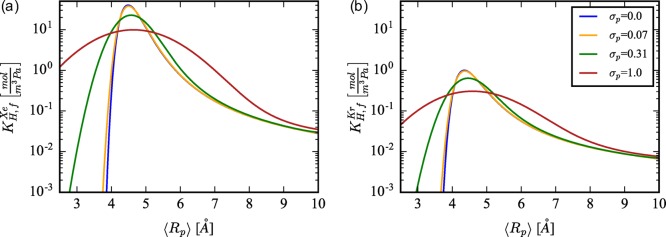
We have developed both a rigid (eq 4) and flexible (eq 5) pore model to obtain insight into flexibility’s effects on Xe/Kr Henry coefficients. The dependence of KH on the pore radius and distribution width is shown in Figure 2. The most interesting consequence of flexibility is that the pore sizes resulting in the largest KH,r are the most overpredictive of KH,f and the pore sizes with smaller KH,r are the most under-predictive of KH,f. The size of these over(under-)predictions is strongly dependent on the strength of pore size fluctuations (σp), which is shown in Figure 2a (Xe) and Figure 2b (Kr) when differing σp values are plotted. The overpredictions occur since there exists a finite probability that the pore deviates from the optimal size, even when the most probable configuration is the optimal size. The under-predictions occur since there exists a finite probability that the pore can adopt the optimal size, even though the most probable configuration is not the optimal size. Thus, the main observation from this analysis is that, even if relatively small fluctuations (σp < 0.4 Å) in a flexible pore average out such that ⟨Rp⟩ is equivalent to Rp in the rigid approximation, the flexible pore Henry coefficient can differ significantly. We will see in subsequent discussions that, similar to the green curve in Figure 2, σp ≈ 0.3 Å for SBMOF-1.
Figure 2.
Broadening of the flexible Henry coefficient profile, KH,f(⟨Rp⟩, σp), is calculated for increasing values of the pore size distribution width, σp = {0.0, 0.07, 0.31, 1.0}, for both (a) a Xe adsorbate and (b) a Kr adsorbate.
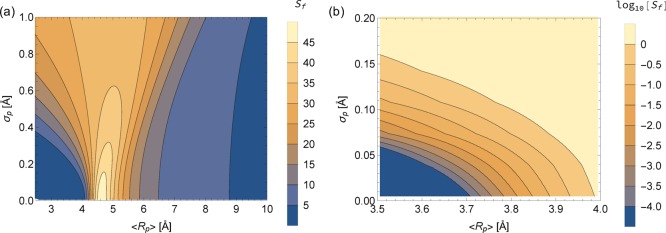
More interesting than just KH from an applications perspective is the infinite dilution selectivity of Xe/Kr, which was formulated for flexible and rigid pores in eqs 6 and 7, respectively. The selectivity for the flexible pore model was calculated over the bounds 2.5 Å < ⟨Rp⟩ < 10.0 and 0.0 Å < σp < 1.0 Å and mapped over this two-dimensional space, as shown in Figure 3. It is immediately evident from Figure 3a that, since the contours are not vertical lines, the rigid pore approximation will yield a different selectivity than a flexible pore (i.e., when σp ≠ 0). Figure 3b additionally reveals extremely sharp gradients in Sf(⟨Rp⟩, σp) when ⟨Rp⟩ is slightly smaller than the optimal size (∼4.7 Å) for Xe selectivity.
Figure 3.
Selectivity of Xe to Kr mapped onto the average pore radius (x dimension) and the distribution width of the radius (y dimension) for the fluctuating pore model. The color scale in (a) is a linear scale of the flexible selectivity, Sf, whereas the color in (b) is the log10 scale of Sf to better emphasize the gradients that exist over small changes in ⟨Rp⟩ and σp.
There are three distinct situations where a flexible pore can result in significantly different predicted selectivity than a rigid pore. First, the optimal pore for Xe selectivity in this analytical model has ⟨Rp⟩ ≈ 4.7 Å and σp = 0 Å. Yet fluctuations on the order of σp ≈ 0.6 Å can reduce the selectivity of such a pore by a factor of 2. Second, a rigid pore predicted to be Kr selective can very easily be nonselective or even Xe selective if the pore undergoes small fluctuations (σp ≈ 0.15 Å). Third, predicted selectivity can be quite different when flexible and rigid ⟨Rp⟩ are not equivalent. If thermal fluctuations in a flexible pore do not average out to the same value as the rigid pore, Sr can vastly overpredict Sf. For example, if a rigid pore has Rp = 4.7 Å and overestimates the average flexible pore ⟨Rp⟩ by 0.6 Å, the rigid selectivity could be reduced by a factor of 50. The sensitivity of adsorption properties to small changes in pore sizes has been shown in the literature when different DFT methods were used to optimize the crystal structure.60−62 However, we are highlighting an entirely different situation where the average pore size changes due to flexibility, an effect which we will demonstrate for real MOF systems later on. Most interestingly, the global optimum for selectivity as a function of flexibility occurs for an entirely rigid pore. This is discussed further in the Flexibility and Optimal Separations section.
Flexibility and Optimal Separations
We have systematically demonstrated how we expect shape selective adsorption separations to have an intricate, nontrivial dependence on intrinsic flexibility, having chosen the specific application of Xe/Kr separations to illustrate our findings.Figure 4 summarizes how this information can be exploited for the design and prediction of better separation materials. To construct this figure, we have extracted Sf from Figure 3 at constant σp and normalized the x-axis of ⟨Rp⟩ by ⟨Rp⟩opt such that the optimal selectivity for a given σp occurs at a value of 1. The global optimum of Sf in (⟨Rp⟩,σp) space occurs when σp = 0.
Figure 4.
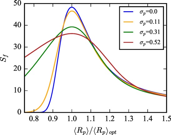
Flexible selectivity from the analytical model is plotted as a function of ⟨Rp⟩ divided by the optimal pore size, ⟨Rp⟩opt, such that the point of optimal selectivity is normalized to 1 for all values of σp. This demonstrates that maximizing selectivity is achieved not simply by having the optimal pore size but also by simultaneously minimizing intrinsic flexibility. Although, interestingly, pore sizes that are smaller than the optimal size can have their selectivity significantly improved with increasing flexibility.
This clearly demonstrates that designing MOFs with the optimal combination of pore size and chemistry is not sufficient to achieve a global optimum in performance; one must minimize intrinsic flexibility while simultaneously realizing the optimal average pore size to achieve the best separation. It also demonstrates that, while fluctuations reduce the selectivity of the optimally rigid pore, sufficiently large fluctuations expand the range of average pore sizes (or the number of MOFs) for which flexibility can improve selectivity. Nonetheless, the global optimum in ⟨Rp⟩ and σp space occurs for σp = 0. In other words, if one could design the perfectly optimal rigid pore with the ideal size and chemical composition, increasing flexibility would only lead to worse performance. These results provide a guiding principle in the rational design of nanoporous materials for shape selective separations and are validated when studying the effects of flexibility on Xe/Kr adsorption in real systems, i.e., the CoRE MOF database, which is the focus of subsequent discussion.
Flexibility in CoRE MOF Screening
From the analytical model it is evident that flexibility is important when a material’s pores approach the same size as the adsorbed molecules. For a correct screening it is therefore important to take framework flexibility into account, and to do this, we calculate Sf with the reported CoRE MOF experimental structure as the starting framework configuration and input for UFF-FM. Three plots are instructive for comparison with the results from the analytical model.
First, the Henry coefficient of Xe in the flexible material (KH,fXe) is plotted versus the corresponding rigid Henry coefficient (KH,r) in Figure 5, and each material is color coded by their largest included sphere (Di).59 For materials with very large Di, the rigid and flexible calculations tend to give equitable results for the Xe Henry coefficient. However, for smaller pores and those that are the optimal size for Xe selectivity, orders of magnitude discrepancy can exist between the calculated Henry coefficients for the flexible structure and the rigid approximation. This discrepancy is attributed to pore size fluctuations, slight changes in ⟨Rp⟩, or a combination of both, all of which is clearly demonstrated by the results of the analytical model shown in Figures 2 and 3.
Figure 5.
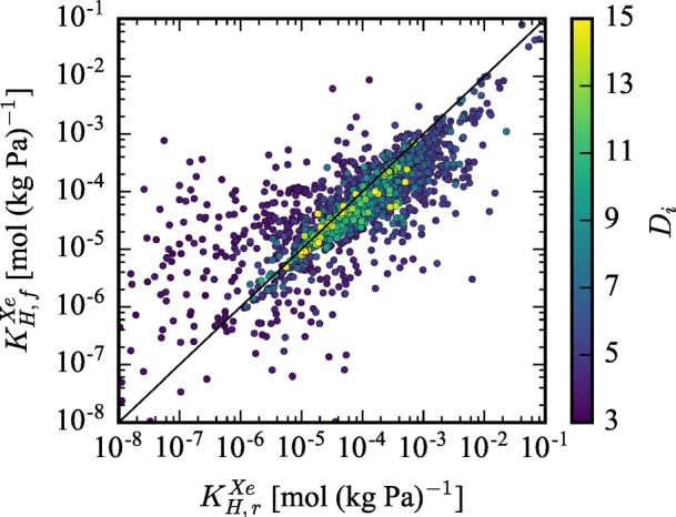
Flexible Xe Henry coefficient (KH,fXe) is plotted versus the rigid Xe Henry coefficient (KH,r). The color-coding of materials by their largest included sphere shows that the rigid approximation tends to perform worse as a material’s pore size decreases.
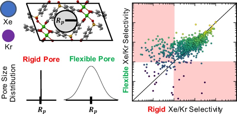
Second, Figure 6 plots the flexible selectivity versus the rigid selectivity, and data points are color coded by the material’s KH,fXe such that the most interesting materials in terms of Xe affinity are colored yellow. Purple colored materials by comparison are expected to have very low infinite dilution uptake. The rigid approximation performs decently for some structures which remain on the y = x line of parity. However, there is very noticeable scatter, and considering flexibility can result in orders of magnitude deviation. Among top performing structures from the entire screening, Sr almost always overestimates Sf, supporting our conclusion that rigid pores are the globally optimal solution since, if a material already achieves the optimal pore size for a given chemistry, fluctuations will only reduce the selectivity. Medium performing structures tend to have both significant over(under-)estimations, while the lowest performing rigid structures tend to exhibit a huge underestimation of the selectivity. This systematic dependency is visualized another way in Figure 6b, where the histogram shows that, among top performing structures, simulating flexibility reduces performance in ∼95% of materials. By contrast, for the lowest performing MOFs, flexibility increases performance in ∼90% of the materials. The red highlighted regions in Figure 6a show where the rigid and flexible simulations predict reverse selectivity. Thus, a pore that was a good fit for Xe can become too small (lower right region), or one that was too small can become enlarged and favorable by intrinsic flexibility (upper left region) and result in a material with large selectivity for Xe. This systematic behavior has already been predicted by the solution of the analytical model shown in Figure 3.
Figure 6.
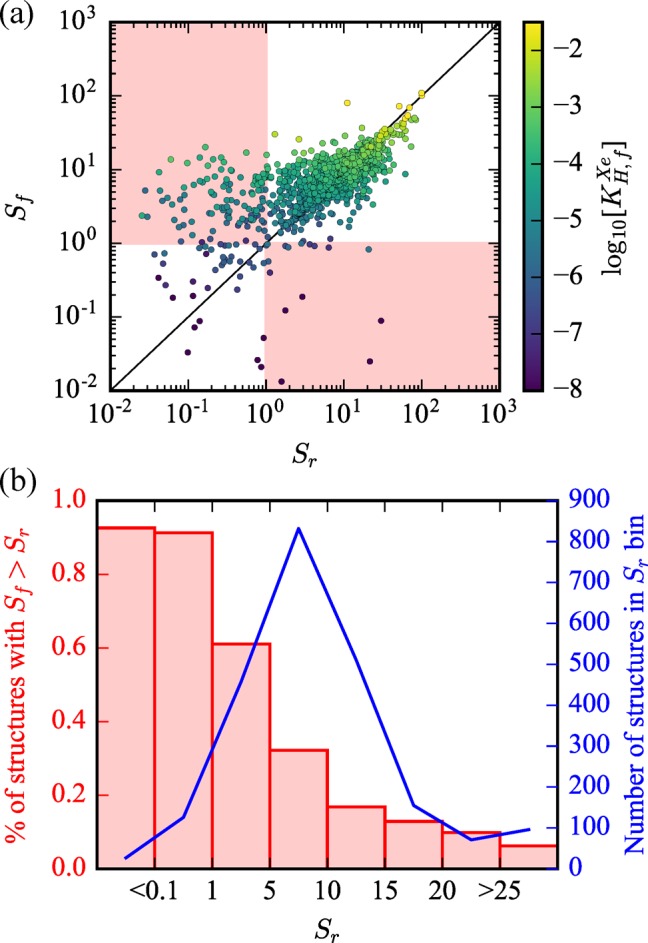
(a) Flexible selectivity is plotted versus rigid approximation selectivity for screened CoRE MOFs. Highlighted regions in red demonstrate areas where the rigid approximation and the flexible simulations predict reverse selectivity of one another. Materials are color coded by the log10 value of the flexible Xe Henry coefficient, KH,fXe [mol (kg Pa)−1], to highlight the best flexible materials for Xe infinite dilution uptake. (b) A histogram view of the same data is shown. The red histogram shows that the larger the rigid selectivity becomes (i.e., the more optimal the pore size and chemistry), the more frequently that flexibility actually reduces the performance.
Finally, we plot the relative error of the rigid approximation (Sf/Sr) in log10 scale versus Di in Figure 7. We observe exactly what one might expect given the results of the analytical model. The divergence of Sf from Sr increases as the pore size decreases and is very significant in the range of Di for optimal Xe selectivity. Additionally, the analytical model is mapped onto the screening results in Figure 7 by converting ⟨Rp⟩ to Di via eq 8:
| 8 |
where Dcarbon = 3.4 Å is the van der Waals diameter of a carbon atom. The black, red, and purple lines represent Sf/Sr for σp values of 0.005, 0.04, and 0.35, respectively. The trend in the screening data is captured well by the analytical model despite its simplicity in assuming all pore wall atoms are carbon and are arranged in a perfectly spherical shell. Superimposing the analytical model in this way also does not account for when the flexible and rigid ⟨Rp⟩ are not identical for a particular material. This effect, which is demonstrated in subsequent discussion, would additionally change how the analytical model is mapped on Figure 7. Most importantly, these analyses demonstrate that the screening results agree with the analytical model: The best rigid approximation materials (which ignore framework fluctuations) overestimate the selectivity when flexibility is considered.
Figure 7.
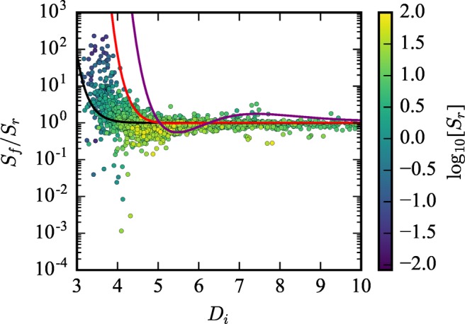
Relative error from the rigid structure approximation, Sf/Sr, is plotted in log10 scale against Di. Each material is color-coded by log10[Sr]. The screening results are compared to the analytical model where the solid black, red, and purple lines represent Sf(Di, σp = 0.005)/Sr(Di), Sf(Di, σp = 0.04)/Sr(Di), and Sf(Di, σp = 0.35)/Sr(Di), respectively.
We caution that our screening calculations were not performed using a pocket-blocking algorithm since flexibility in points of constriction in the pore network makes the accessibility of pockets a function of time. Instead the screening results are only visualized for structures where KH,rXe > 1 × 10⁻⁸ mol/(kg·Pa) as an approximate way to filter out nonporous structures. We closely investigate and explain the performance of selected structures, for which we manually ensure that pockets of inaccessibility do not exist, via comparison to the analytical model in the following section.
Flexibility in Selected CoRE MOFs
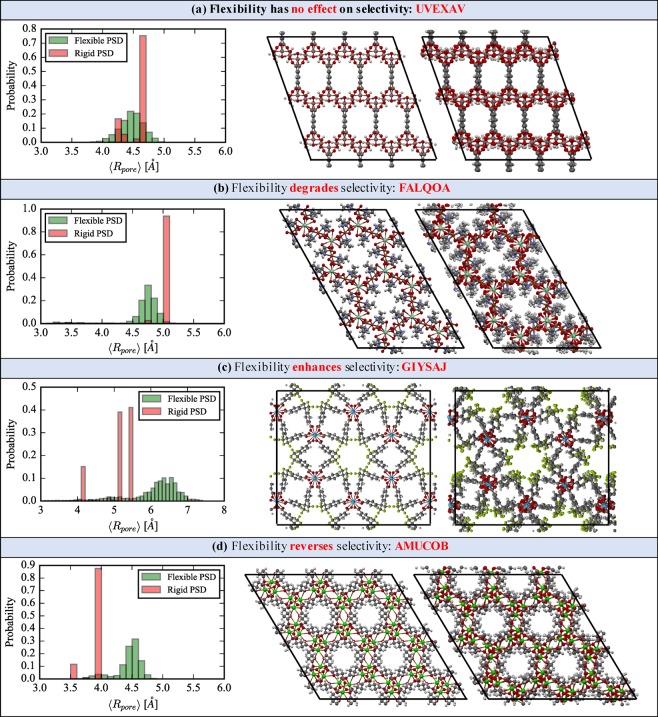
Several MOFs are selected from the screening study to illustrate in greater detail the various ways in which flexibility changes the selectivity by comparison to the rigid structure approximation. For these structures, NVT simulations show that the rigid pore approximation does not present a good statistical representation of the PSD when the host framework fluctuates at room temperature. Figure 8 presents a visual analysis of flexibility in four selected CoRE MOFs and demonstrates how thermal fluctuations affect the PSD and thus the Xe/Kr selectivity. For each material we show the flexible/rigid PSD as well as visualization of the rigid structure (left image) and a snapshot of the flexible structure (right image) from the UFF-FM MD run. The corresponding flexible and rigid Henry coefficients and selectivity are summarized in Table 1.
Figure 8.
Evolution of the PSD after NVT dynamics is shown for four CoRE MOFs, with the experimental structure (left image) and a snapshot from the flexible simulation (right image). Sections (a–d) show specific cases for which flexibility has no effect, degrades, enhances, or reverses the Xe/Kr selectivity, respectively.
Table 1. Flexible and Rigid Henry Coefficients and Selectivity for the Four CoRE MOFs Shown in Figure 8.
|
KH,f [mol/(kg·Pa)] |
KH,r [mol/(kg·Pa)] |
|||||
|---|---|---|---|---|---|---|
| CSD code | Xe | Kr | Xe | Kr | Sf | Sr |
| UVEXAV | 1.0 × 10⁻² | 3.5 × 10⁻⁴ | 1.1 × 10⁻² | 3.8 × 10⁻⁴ | 29 | 29 |
| FALQOA | 2.1 × 10⁻³ | 4.5 × 10⁻⁵ | 1.3 × 10⁻² | 1.6 × 10⁻⁴ | 47 | 81 |
| GIYSAJ | 8.9 × 10⁻⁴ | 3.0 × 10⁻⁵ | 1.4 × 10⁻³ | 5.3 × 10⁻⁵ | 30 | 26 |
| AMUCOB | 4.3 × 10⁻⁴ | 2.5 × 10⁻⁵ | 2.9 × 10⁻⁶ | 5.2 × 10⁻⁶ | 17 | 0.56 |
In Figure 8a, UVEXAV (MIL-120)63 demonstrates a situation where the selectivity remains unaffected by flexibility. The rigid PSD reveals two pores that are very close in size, but notably the flexible PSD shows a continuous distribution with approximately the same mean, resulting in unchanged KH and Sf ≈ Sr. Figure 8b highlights FALQOA,64 a material for which flexibility reduces Sr. The rigid PSD demonstrates a pore that is of very favorable size for Xe adsorption which shrinks only slightly throughout the MD run. However, the sensitivity of the Henry coefficient to ⟨Rp⟩ is sufficient to lower KH,fXe by an order of magnitude and halve the selectivity when flexibility is considered. The most complex PSD in this set of examples is exhibited by GIYSAJ (RPF-4),65 as shown in Figure 8c for which flexibility serves to slightly enhance the selectivity. Flexible simulations show that the smallest pore can essentially be blocked due to ring rotation and the large pore shifts to a higher mean value. Both effects serve to decrease the Henry coefficients in the flexible structure but in such a way as to slightly raise the selectivity overall. AMUCOB (BioMIL-2)66 in Figure 8d presents arguably the most interesting behavior, as it is Kr selective under the rigid pore approximation but very Xe selective when flexibility is considered due to an overall increase in pore size. AMUCOB is just one of several CoRE MOFs to display this phenomena as previously discussed with Figure 6. Additionally, we note that each structure’s flexible selectivity is higher than the experimental selectivity of SBMOF-1, a material which is the focus of discussion in the following section.
Flexibility in SBMOF-1
The screening data and the analytical model demonstrate that when a given material already has the optimal pore size to maximize selectivity, increasing intrinsic pore flexibility only serves to reduce the selectivity performance. This effect can be shown in the context of a particular well-known Xe/Kr separations system. Here our flexibility calculations are benchmarked against experimental results for the highly performing Xe/Kr separation material, SBMOF-1, to once again show that pore flexibility reduces the performance in selectivity of optimal rigid materials. This system was chosen since it was identified as the best performer from a high-throughput screening study22 but showed a large discrepancy between experimental and computational Henry coefficients when using the rigid pore approximation.23 Thus, we focus on this structure to show how consideration of framework flexibility better aligns computations with experiments and reduces the optimal selectivity. DFT/PBE+D3, UFF-FM, and UFF-CDM were all used to model framework dynamics in SBMOF-1, and the resulting Henry coefficient and selectivity calculations are summarized in Table 2. The rigid structure approximation of SBMOF-1 (KAXQIL) has the optimal pore size for maximizing the Xe Henry coefficient and selectivity. However, considering flexibility reduces these quantities and leads to better agreement with experiments. UFF-CDM generated dynamics provide the best agreement with experiments, and there exists a significant decrease in the Henry coefficients and selectivity when compared to the rigid pore approximation.
Table 2. Henry Coefficients and Selectivity in SBMOF-1 for the Rigid Pore Approximation and Various Framework Dynamics Methodsa.
|
KH [mol/(kg·Pa)] |
||||
|---|---|---|---|---|
| description | flexibility | Xe | Kr | SXe/Kr |
| experimental data | N/A | 3.84 × 10⁻⁴ | 2.37 × 10⁻⁵ | 16 |
| KAXQIL deposited structure | no | 1.45 × 10⁻² | 2.70 × 10⁻⁴ | 54 |
| KAXQIL DFT optimized | no | 1.03 × 10⁻² | 2.20 × 10⁻⁴ | 47 |
| AIMD (1 × 2 × 1) | yes | 7.49 × 10⁻³ | 1.85 × 10⁻⁴ | 41 |
| AIMD (2 × 2 × 1) | yes | 6.80 × 10⁻³ | 1.77 × 10⁻⁴ | 38 |
| AIMD (1 × 3 × 1) | yes | 6.68 × 10⁻³ | 1.72 × 10⁻⁴ | 39 |
| UFF-FM | yes | 6.24 × 10⁻³ | 1.67 × 10⁻⁴ | 37 |
| UFF-CDM | yes | 3.18 × 10⁻³ | 1.28 × 10⁻⁴ | 25 |
The “Description” column gives the simulation type (and number of unit cell replications used in the AIMD simulation), and the “Flexibility” column denotes a flexible simulation. Experimental data from ref (23) is included.
This decrease in Henry coefficients fundamentally arises from thermal disordering in SBMOF-1, visualized in Figure 9. The impact of flexibility on the PSD for each dynamics method is quantitatively shown in Figure 10. While the rigid pores are of optimal size for maximizing selectivity, the existence of flexibility in all cases leads to pore size fluctuations and a shrinking of average pore size away from its optimal value. As predicted by the analytical model, both effects can serve to reduce the Henry coefficients (of both Xe and Kr) and the overall selectivity of the material.
Figure 9.
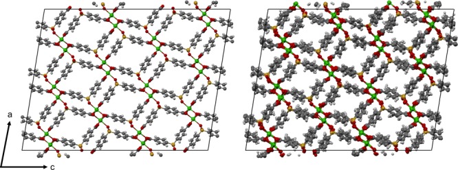
DFT optimized cell (replicated 3 × 6 × 2) is depicted on the left, while a snapshot from a MD trajectory generated with UFF-CDM is depicted on the right. Thermal disordering of the structure results in a change in the PSD accessible to Xe/Kr adsorbates.
Figure 10.
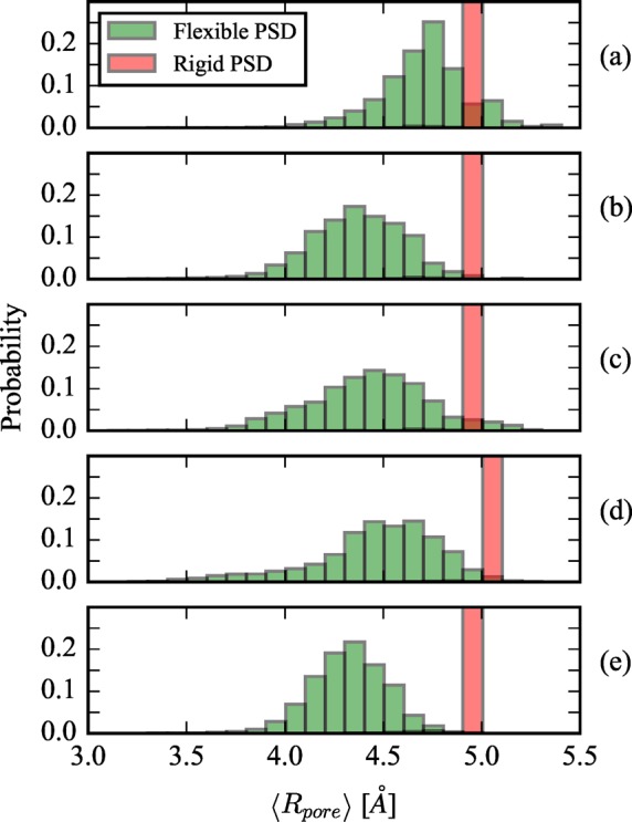
Evolution of the PSD is shown from the rigid structure (red histogram) to the flexible structure (green histogram). (a–c) PSD for 1 × 2 × 1, 2 × 2 × 1, and 1 × 3 × 1 AIMD, respectively, where the rigid structure corresponds to the DFT minimized framework. (d) PSD for UFF-FM with the rigid structure corresponding to the KAXQIL experimentally resolved framework. and (e) PSD for UFF-CDM where the rigid structure is the DFT minimized framework.
For DFT/PBE+D3, only a small number of unit cell replications is computationally feasible. Interestingly, 1 × 2 × 1, 2 × 2 × 1, and 1 × 3 × 1 simulations all display different PSDs, suggesting that the flexibly determined PSD can be system size dependent, since the system is simply too constrained when considering only one and two replications in certain crystallographic directions. Similar finite size effects have recently been reported where multiple unit cell replications were necessary to observe crystallographic deformations.16 However, the key feature is that the mean pore size always decreases leading to reduced Henry coefficients of both adsorbates, which is accompanied by a reduction in the selectivity. The identical trend is observed in the larger classical simulations. Thus, a major finding from this analysis is that, for all flexible simulation methods, the thermodynamic fluctuations do not average out to the rigid pore approximation. Different methods (classical vs ab initio) for host framework dynamics yield similar evolution of the PSD’s from the rigid to flexible simulations, and the computed KH,f is always in better agreement with experiments due to the decrease in ⟨Rp⟩.
It should be noted that the nonbonded parameters for guest–framework interactions also have an effect on the predicted Henry coefficients and selectivity. We find that the Boato and UFF parameters for guest–framework interactions do not perfectly replicate the DFT/PBE+D3 potential energy surface, which is shown in the SI. Regardless, the data presented here show the large dependence of the adsorption properties on flexibly induced changes in the pore size.
Conclusions
The chemical tunability of MOFs is constantly exploited to create adsorption sites with a high selectivity. However, in the case of shape selective adsorption separations where the pore size and shape are commensurate with similarly sized adsorbates like Xe/Kr, the efficiency of these adsorption sites for separations relies on subtle geometric differences, which we have shown to be strongly influenced by flexibility. In this work we have systematically addressed the nontrivial dependence of selectivity on intrinsic flexibility, providing a comprehensive outlook for the design and/or identification of optimal shape selective separation materials in the context of Xe/Kr mixtures. Quantification of the effect of flexibility on the separation of Xe/Kr mixtures using an analytical model and molecular simulations shows that some materials’ selectivity can be increased, while others’ decreased by flexibility. However, for those materials already displaying the optimal pore size for a given pore chemistry, increasing pore size fluctuations serve only to further decrease selectivity. Hence the design of a globally optimal separation must not only focus on optimizing pore size and chemistry but also on minimizing intrinsic flexibility. From an experimental design point of view, one must simultaneously aim for MOFs with ligands, coordination environments, and topologies that constitute the most rigid framework possible and the optimal pore size and chemistry to achieve maximum possible selectivity.
An equally important part of this work discusses the validity of the rigid framework approximation in shape selective adsorption applications. In most computational high-throughput screening studies, the MOF structure is assumed to be rigid for computational efficiency reasons, and we investigated whether this assumption has biased the selection of optimal materials. Our results show that, among the top performing structures in the rigid framework approximation, simulations accounting for flexibility lead to a reduction of selectivity in ∼95% of these materials. Conversely, this screening also demonstrated that fluctuations alone can cause a material to reverse its selectivity when the average pore size is less than the optimal value for Xe adsorption. Among the lowest performing structures in the rigid framework approximation, ∼90% of these materials had their selectivity increased when accounting for framework flexibility. These results suggest that flexibility should be considered in shape selective screening studies for the highest degree of accuracy possible and to achieve the best ranking of high-performance materials.
SBMOF-1, which was recently crowned as the material with the highest Xe/Kr selectivity from a computational screening of rigid MOFs, was re-evaluated with flexibility using both ab initio and classical MD calculations. This resulted in better agreement with experimental data. Naturally the question then arises if there are materials which can be experimentally demonstrated to have better Xe/Kr selectivity than SBMOF-1. We have presented four structures (CSD reference codes UVEXAV, FALQOA, GIYSAJ, and AMUCOB) identified in our screening study whose predicted Sf is higher than the experimental selectivity of SBMOF-1 and used each structure’s PSD evolution in NVT simulations to observe how flexibility affects Xe and Kr Henry regime uptake. Through a variety of MD methods, we demonstrated that flexibility always serves to reduce the Henry coefficients of Xe and Kr and selectivity in SBMOF-1, bringing better alignment between experimental results and computational predictions for this material’s adsorption properties.
The concepts developed in this work can now be applied to other shape selective separations. Such an example would be CO2/CH4 separations where, like Xe/Kr mixtures, the kinetic diameters of both adsorbates are of similar size. Here one would expect intrinsic flexibility to affect the Henry regime selectivity as well. Similar to Xe/Kr separations, there would exist an optimal pore size and chemistry that maximizes the rigid selectivity for one of the adsorbates, but the more flexible this optimal pore is, the more the selectivity will be reduced. And while our analytical model only accounts for isotropic pore deformations, it would also be useful to develop another model in which an additional flexibility parameter characterizes the degree of anisotropy of the pore deformation since CH4 is an isotropic particle but CO2 is not. This development of more intricate analytical models in conjunction with a similar screening of flexible CoRE MOFs could lead to new insights regarding the usefulness of MOFs for CO2/CH4 separations.
Finally, we re-emphasize that we have focused on predicting Henry regime selectivity. However, both the analytical model and the flexible screening methods could be extended to obtain selectivity at higher pressures with additional assumptions and more computational cost, respectively. In the cases of higher pressure, the adsorption behavior will then depend on the exact potential energy profile of the host as a function of the pore size, since less energetically favorable conformations of the framework can be stabilized with increasing chemical potential. Thus, it is likely that new insights will be obtained for the selectivity dependence at higher pressures. Such future work will have two major benefits. First, we will understand if the trends observed in this work between flexibility and separation performance hold at high pressure (where many separations are performed). Second, we will be able to determine over what pressure ranges Henry’s law is applicable in flexible materials and whether it differs from the Henry regime pressure range in the rigid pore approximation.
Acknowledgments
M.W. and B. Smit were supported by the Center for Gas Separations Relevant to Clean Energy Technologies, an Energy Frontier Research Center funded by the U.S. Department of Energy, Office of Science, Basic Energy Sciences under award DE-SC0001015 for analytical model development and adsorption calculations in flexible materials. S.L. and B. Slater were supported by EPSRC (EP/K039296/1 and EP/K038400/1) for studies on AIMD simulations. S.J. acknowledges support from an NSF Graduate Research Fellowship for implementation of classical force fields. P.B.’s research has received funding from the European Research Council (ERC) under the European Union’s Horizon 2020 research and innovation programme (grant agreement no. 666983, MaGic) for the implementation of classical force fields. M.H. was supported by the Center for Applied Mathematics for Energy Related Applications (CAMERA) under contract no. DE-AC02-05CH11231 for development of tools for pore characterization. This research used resources of the National Energy Research Scientific Computing Center (NERSC), which is supported by the Office of Science of the U.S. Department of Energy under contract no. DE-AC02-05CH11231. Part of the computational work was performed on ARCHER through our membership of the HPC Materials Chemistry Consortium funded by EPSRC (EP/L000202).
Supporting Information Available
The Supporting Information is available free of charge on the ACS Publications website at DOI: 10.1021/jacs.7b01688.
Supporting simulation files (ZIP)
Additional simulation details; potential energy landscape of Xe/Kr in SBMOF-1; download and visualization of screening data available at http://www.materialscloud.org/archive/2017.0003/v1/ (PDF)
The authors declare no competing financial interest.
Supplementary Material
References
- Liu J.; Thallapally P. K.; McGrail B. P.; Brown D. R.; Liu J. Chem. Soc. Rev. 2012, 41, 2308–2322. 10.1039/C1CS15221A. [DOI] [PubMed] [Google Scholar]
- Mason J. A.; Veenstra M.; Long J. R. Chem. Sci. 2014, 5, 32–51. 10.1039/C3SC52633J. [DOI] [Google Scholar]
- Murray L. J.; Dincă M.; Long J. R. Chem. Soc. Rev. 2009, 38, 1294. 10.1039/b802256a. [DOI] [PubMed] [Google Scholar]
- Kreno L. E.; Leong K.; Farha O. K.; Allendorf M.; Van Duyne R. P.; Hupp J. T. Chem. Rev. 2012, 112, 1105–1125. 10.1021/cr200324t. [DOI] [PubMed] [Google Scholar]
- Ranocchiari M.; van Bokhoven J. A. Phys. Chem. Chem. Phys. 2011, 13, 6388. 10.1039/c0cp02394a. [DOI] [PubMed] [Google Scholar]
- Li J.-R.; Sculley J.; Zhou H.-C. Chem. Rev. 2012, 112, 869–932. 10.1021/cr200190s. [DOI] [PubMed] [Google Scholar]
- Yaghi O. M.; O’Keeffe M.; Ockwig N. W.; Chae H. K.; Eddaoudi M.; Kim J. Nature 2003, 423, 705–714. 10.1038/nature01650. [DOI] [PubMed] [Google Scholar]
- Schneemann A.; Bon V.; Schwedler I.; Senkovska I.; Kaskel S.; Fischer R. A. Chem. Soc. Rev. 2014, 43, 6062–6096. 10.1039/C4CS00101J. [DOI] [PubMed] [Google Scholar]
- Férey G.; Serre C. Chem. Soc. Rev. 2009, 38, 1380. 10.1039/b804302g. [DOI] [PubMed] [Google Scholar]
- Bousquet D.; Coudert F.-X.; Boutin A. J. Chem. Phys. 2012, 137, 044118. 10.1063/1.4738776. [DOI] [PubMed] [Google Scholar]
- Mason J. A.; Oktawiec J.; Taylor M. K.; Hudson M. R.; Rodriguez J.; Bachman J. E.; Gonzalez M. I.; Cervellino A.; Guagliardi A.; Brown C. M.; Llewellyn P. L.; Masciocchi N.; Long J. R. Nature 2015, 527, 357–361. 10.1038/nature15732. [DOI] [PubMed] [Google Scholar]
- Mellot-Draznieks C.; Serre C.; Surblé S.; Audebrand N.; Férey G. J. Am. Chem. Soc. 2005, 127, 16273–16278. 10.1021/ja054900x. [DOI] [PubMed] [Google Scholar]
- Lin Z.-J.; Lü J.; Hong M.; Cao R. Chem. Soc. Rev. 2014, 43, 5867–5895. 10.1039/C3CS60483G. [DOI] [PubMed] [Google Scholar]
- Simon C. M.; Braun E.; Carraro C.; Smit B. Proc. Natl. Acad. Sci. U. S. A. 2017, 114, E287–E296. 10.1073/pnas.1613874114. [DOI] [PMC free article] [PubMed] [Google Scholar]
- Sakata Y.; Furukawa S.; Kondo M.; Hirai K.; Horike N.; Takashima Y.; Uehara H.; Louvain N.; Meilikhov M.; Tsuruoka T.; Isoda S.; Kosaka W.; Sakata O.; Kitagawa S. Science 2013, 339, 193–196. 10.1126/science.1231451. [DOI] [PubMed] [Google Scholar]
- Jawahery S.; Simon C. M.; Braun E.; Witman M.; Tiana D.; Vlaisavljevich B.; Smit B. Nat. Commun. 2017, 8, 13945. 10.1038/ncomms13945. [DOI] [PMC free article] [PubMed] [Google Scholar]
- Maji T. K.; Matsuda R.; Kitagawa S. Nat. Mater. 2007, 6, 142–148. 10.1038/nmat1827. [DOI] [PubMed] [Google Scholar]
- Krause S.; Bon V.; Senkovska I.; Stoeck U.; Wallacher D.; Többens D. M.; Zander S.; Pillai R. S.; Maurin G.; Coudert F.-X.; Kaskel S. Nature 2016, 532, 348–352. 10.1038/nature17430. [DOI] [PubMed] [Google Scholar]
- Evans J. D.; Bocquet L.; Coudert F.-X. Chem. 2016, 1, 873–886. 10.1016/j.chempr.2016.11.004. [DOI] [Google Scholar]
- Haldoupis E.; Watanabe T.; Nair S.; Sholl D. S. ChemPhysChem 2012, 13, 3449–3452. 10.1002/cphc.201200529. [DOI] [PubMed] [Google Scholar]
- Chen L.; Reiss P. S.; Chong S. Y.; Holden D.; Jelfs K. E.; Hasell T.; Little M. A.; Kewley A.; Briggs M. E.; Stephenson A.; Thomas K. M.; Armstrong J. A.; Bell J.; Busto J.; Noel R.; Liu J.; Strachan D. M.; Thallapally P. K.; Cooper A. I. Nat. Mater. 2014, 13, 954–960. 10.1038/nmat4035. [DOI] [PubMed] [Google Scholar]
- Simon C. M.; Mercado R.; Schnell S. K.; Smit B.; Haranczyk M. Chem. Mater. 2015, 27, 4459–4475. 10.1021/acs.chemmater.5b01475. [DOI] [Google Scholar]
- Banerjee D.; Simon C. M.; Plonka A. M.; Motkuri R. K.; Liu J.; Chen X.; Smit B.; Parise J. B.; Haranczyk M.; Thallapally P. K. Nat. Commun. 2016, 7, 11831. 10.1038/ncomms11831. [DOI] [PMC free article] [PubMed] [Google Scholar]
- Nazarian D.; Camp J. S.; Sholl D. S. Chem. Mater. 2016, 28, 785–793. 10.1021/acs.chemmater.5b03836. [DOI] [Google Scholar]
- Boyd P. G.; Moosavi S. M.; Witman M.; Smit B. J. Phys. Chem. Lett. 2017, 8, 357–363. 10.1021/acs.jpclett.6b02532. [DOI] [PMC free article] [PubMed] [Google Scholar]
- Wilmer C. E.; Leaf M.; Lee C. Y.; Farha O. K.; Hauser B. G.; Hupp J. T.; Snurr R. Q. Nat. Chem. 2011, 4, 83–89. 10.1038/nchem.1192. [DOI] [PubMed] [Google Scholar]
- Martin R. L.; Haranczyk M. Cryst. Growth Des. 2014, 14, 2431–2440. 10.1021/cg500158c. [DOI] [Google Scholar]
- Boyd P. G.; Woo T. K. CrystEngComm 2016, 18, 3777–3792. 10.1039/C6CE00407E. [DOI] [Google Scholar]
- Witman M.; Ling S.; Anderson S.; Tong L.; Stylianou K. C.; Slater B.; Smit B.; Haranczyk M. Chem. Sci. 2016, 7, 6263–6272. 10.1039/C6SC01477A. [DOI] [PMC free article] [PubMed] [Google Scholar]
- Sarkisov L.; Martin R. L.; Haranczyk M.; Smit B. J. Am. Chem. Soc. 2014, 136, 2228–2231. 10.1021/ja411673b. [DOI] [PubMed] [Google Scholar]
- Cox B. J.; Thamwattana N.; Hill J. M. Proc. R. Soc. London, Ser. A 2007, 463, 477–494. 10.1098/rspa.2006.1772. [DOI] [Google Scholar]
- Frenkel D.; Smit B.. Understanding Molecular Simulation; Elsevier: San Diego, 2002. [Google Scholar]
- Manz T. A.; Sholl D. S. J. Chem. Theory Comput. 2010, 6, 2455–2468. 10.1021/ct100125x. [DOI] [PubMed] [Google Scholar]
- Mayo S. L.; Olafson B. D.; Goddard W. A. J. Phys. Chem. 1990, 94, 8897–8909. 10.1021/j100389a010. [DOI] [Google Scholar]
- Rappe A. K.; Casewit C. J.; Colwell K. S.; Goddard W. A.; Skiff W. M. J. Am. Chem. Soc. 1992, 114, 10024–10035. 10.1021/ja00051a040. [DOI] [Google Scholar]
- Bristow J. K.; Tiana D.; Walsh A. J. Chem. Theory Comput. 2014, 10, 4644–4652. 10.1021/ct500515h. [DOI] [PMC free article] [PubMed] [Google Scholar]
- Addicoat M. A.; Vankova N.; Akter I. F.; Heine T. J. Chem. Theory Comput. 2014, 10, 880–891. 10.1021/ct400952t. [DOI] [PubMed] [Google Scholar]
- Banerjee D.; Zhang Z.; Plonka A. M.; Li J.; Parise J. B. Cryst. Growth Des. 2012, 12, 2162–2165. 10.1021/cg300274n. [DOI] [Google Scholar]
- Duarte F.; Bauer P.; Barrozo A.; Amrein B. A.; Purg M.; Åqvist J.; Kamerlin S. C. L. J. Phys. Chem. B 2014, 118, 4351–4362. 10.1021/jp501737x. [DOI] [PMC free article] [PubMed] [Google Scholar]
- Plimpton S. J. Comput. Phys. 1995, 117, 1–19. 10.1006/jcph.1995.1039. [DOI] [Google Scholar]
- VandeVondele J.; Krack M.; Mohamed F.; Parrinello M.; Chassaing T.; Hutter J. Comput. Phys. Commun. 2005, 167, 103–128. 10.1016/j.cpc.2004.12.014. [DOI] [Google Scholar]
- Hutter J.; Iannuzzi M.; Schiffmann F.; VandeVondele J. Wiley Interdiscip. Rev. Comput. Mol. Sci. 2014, 4, 15–25. 10.1002/wcms.1159. [DOI] [Google Scholar]
- VandeVondele J.; Hutter J. J. Chem. Phys. 2007, 127, 114105. 10.1063/1.2770708. [DOI] [PubMed] [Google Scholar]
- Goedecker S.; Teter M.; Hutter J. Phys. Rev. B: Condens. Matter Mater. Phys. 1996, 54, 1703–1710. 10.1103/PhysRevB.54.1703. [DOI] [PubMed] [Google Scholar]
- Krack M. Theor. Chem. Acc. 2005, 114, 145–152. 10.1007/s00214-005-0655-y. [DOI] [Google Scholar]
- Perdew J. P.; Burke K.; Ernzerhof M. Phys. Rev. Lett. 1996, 77, 3865–3868. 10.1103/PhysRevLett.77.3865. [DOI] [PubMed] [Google Scholar]
- Grimme S.; Antony J.; Ehrlich S.; Krieg H. J. Chem. Phys. 2010, 132, 154104. 10.1063/1.3382344. [DOI] [PubMed] [Google Scholar]
- Ling S.; Slater B. Chem. Sci. 2016, 7, 4706–4712. 10.1039/C5SC04953A. [DOI] [PMC free article] [PubMed] [Google Scholar]
- Nanthamathee C.; Ling S.; Slater B.; Attfield M. P. Chem. Mater. 2015, 27, 85–95. 10.1021/cm503311x. [DOI] [Google Scholar]
- Tran F.; Hutter J. J. Chem. Phys. 2013, 138, 204103. 10.1063/1.4807332. [DOI] [PubMed] [Google Scholar]
- Boys S.; Bernardi F. Mol. Phys. 1970, 19, 553–566. 10.1080/00268977000101561. [DOI] [Google Scholar]
- Bussi G.; Donadio D.; Parrinello M. J. Chem. Phys. 2007, 126, 014101. 10.1063/1.2408420. [DOI] [PubMed] [Google Scholar]
- Campañá C.; Mussard B.; Woo T. K. J. Chem. Theory Comput. 2009, 5, 2866–2878. 10.1021/ct9003405. [DOI] [PubMed] [Google Scholar]
- Golze D.; Hutter J.; Iannuzzi M. Phys. Chem. Chem. Phys. 2015, 17, 14307–14316. 10.1039/C4CP04638B. [DOI] [PubMed] [Google Scholar]
- Witman M.; Ling S.; Gladysiak A.; Stylianou K. C.; Smit B.; Slater B.; Haranczyk M. J. Phys. Chem. C 2017, 121, 1171–1181. 10.1021/acs.jpcc.6b10363. [DOI] [PMC free article] [PubMed] [Google Scholar]
- Widom B. J. Chem. Phys. 1963, 39, 2808–2812. 10.1063/1.1734110. [DOI] [Google Scholar]
- Boato G.; Casanova G. Physica 1961, 27, 571–589. 10.1016/0031-8914(61)90072-6. [DOI] [Google Scholar]
- Dubbeldam D.; Calero S.; Ellis D. E.; Snurr R. Q. Mol. Simul. 2016, 42, 81–101. 10.1080/08927022.2015.1010082. [DOI] [Google Scholar]
- Willems T. F.; Rycroft C. H.; Kazi M.; Meza J. C.; Haranczyk M. Microporous Mesoporous Mater. 2012, 149, 134–141. 10.1016/j.micromeso.2011.08.020. [DOI] [Google Scholar]
- Watanabe T.; Sholl D. S. Langmuir 2012, 28, 14114–14128. 10.1021/la301915s. [DOI] [PubMed] [Google Scholar]
- Lawler K. V.; Hulvey Z.; Forster P. M. Phys. Chem. Chem. Phys. 2015, 17, 18904–18907. 10.1039/C5CP01544H. [DOI] [PubMed] [Google Scholar]
- Nazarian D.; Camp J. S.; Chung Y. G.; Snurr R. Q.; Sholl D. S. Chem. Mater. 2016, 28, 785. 10.1021/acs.chemmater.5b03836. [DOI] [Google Scholar]
- Hajjar R.; Volkringer C.; Loiseau T.; Guillou N.; Marrot J.; Férey G.; Margiolaki I.; Fink G.; Morais C.; Taulelle F. Chem. Mater. 2011, 23, 39–47. 10.1021/cm1025427. [DOI] [Google Scholar]
- Zhuang G.; Chen W.-x.; Zeng G.-n.; Wang J.-g.; Chen W.-l. CrystEngComm 2012, 14, 679–683. 10.1039/C1CE05864A. [DOI] [Google Scholar]
- Gándara F.; Andrés A. D.; Gómez-Lor B.; Gutiérrez-Puebla E.; Iglesias M.; Monge M. A.; Proserpio D. M.; Snejko N. Cryst. Growth Des. 2008, 8, 378–380. 10.1021/cg700796m. [DOI] [Google Scholar]
- Miller S. R.; Horcajada P.; Serre C. CrystEngComm 2011, 13, 1894–1898. 10.1039/C0CE00450B. [DOI] [Google Scholar]
Associated Data
This section collects any data citations, data availability statements, or supplementary materials included in this article.


