Abstract
Four-point electrode systems are commonly used for electric impedance measurements of biomaterials and tissues. We introduce a 2-point system to reduce electrode polarization for heterogeneous measurements of vascular wall. Presence of endoluminal oxidized low density lipoprotein (oxLDL) and lipids alters the electrochemical impedance that can be measured by electrochemical impedance spectroscopy (EIS). We developed a catheter-based 2-point micro-electrode configuration for intravascular deployment in New Zealand White rabbits. An array of 2 flexible round electrodes, 240 μm in diameter and separated by 400 μm was microfabricated and mounted on an inflatable balloon catheter for EIS measurement of the oxLDL-rich lesions developed as a result of high-fat diet-induced hyperlipidemia. Upon balloon inflation, the 2-point electrode array conformed to the arterial wall to allow deep intraplaque penetration via alternating current (AC). The frequency sweep from 10 – 300 kHz generated an increase in capacitance, providing distinct changes in both impedance (Ω) and phase (ϕ) in relation to varying degrees of intraplaque lipid burden in the aorta. Aortic endoluminal EIS measurements were compared with epicardial fat tissue and validated by intravascular ultrasound and immunohistochemistry for plaque lipids and foam cells. Thus, we demonstrate a new approach to quantify endoluminal EIS via a 2-point stretchable electrode strategy.
Keywords: Electrochemical impedance spectroscopy, flexible electronics, lipid-rich plaque, atherosclerosis
INTRODUCTION
Electrochemical impedance spectroscopy (EIS) measures charges stored in tissues by electrical impedance (Z) developed in response to applied alternating current (AC). EIS is the macroscopic representation of the electric field and current density distribution within the experimented samples. Such distribution can be described with Maxwell’s equations, which, under the quasi-electrostatic limit, reduces to5:
| (1) |
where , and σT and εT represent the conductivity and permittivity of the sample, respectively, ω is the angular frequency, denotes the voltage distribution. Current density, , is calculated with known distribution of electric field, . Finally, impedance of the sample, Z, based on Maxwell’s equations, is expressed as:
| (2) |
where S denotes the electrode-tissue interface area, Δφ represents the voltage difference across the two measuring electrodes.
Fat-free tissue is known to be a viable electrical conductor for its high water (approximately 73%) and electrolytes (ions and proteins) content. However, fat tissue is anhydrous and thus, a poor conductor. The high lipid content, including negatively charged active lipids such as oxidized low density lipoprotein (oxLDL)27 and foam cells present in the plaque change the endoluminal electrochemical properties that can be measured by EIS17,28,29,30
The application of microelectrode sensor measures the non-Faraday impedance due to the interface capacitance and non-homogeneities of fatty streaks or pre-atherosclerotic lesions that harbor oxLDL and foam cell infiltrates. Suselbeck et al. measured intravascular EIS using a linear 4-electrode configuration microelectrode (2 × 105 μm in length)30. Our group further reduced the sensor surface area by 2,000-fold using the concentric bipolar microelectrode sensors (300 μm in diameter)4,36 and introduced the balloon-inflatable bipolar electrodes to measure EIS signals from non-homogeneous tissue composition, non-planar endoluminal surface, and non-uniform electric current distribution of the atherosclerotic lesions4
We hereby introduce a 2-point configuration to avoid separate current paths and common-mode signals that confound measured data13. The 2-point configuration with flexible round electrodes (Ø 240 μm, Fig. 1) enabled deep intraplaque penetration by AC current, allowing for quantification of oxLDL-rich plaque from the thoracic to distal abdominal aortas in the NZW rabbit model. We biased an input peak-to-peak AC voltage of 50 mV and a sweeping frequency from 10 to 300 kHz to the 2-point electrodes. We quantified and validated EIS signals both in vivo and ex vivo in relation to epicardial fat tissue, and recapitulated the frequency range from 10 – 300 kHz in which distinct capacitive and phase changes revealed low, intermediate and high oxLDL-rich lesions. Thus, we demonstrated a simplified 2-point electrode design to enhance detection of lipid-laden plaques.
Figure 1.
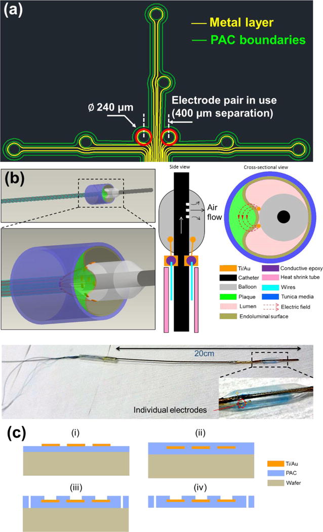
(a) Design schematic of an array of individually addressable impedance sensing electrodes. A set of eight round electrodes (Ø 240 μm) was implemented. The electrode pair situated in the center (400 μm separation) and highlighted in red was selected for measurements throughout the study. (b) 3D rendering of the deployed EIS sensor in contact with a plaque, and 2D side-view of the device illustrating microelectrode placement with adjacent 2D cross-sectional view illustrating apposition and contact of the electrodes on the inflated balloon with the endoluminal surface covering an atherosclerotic plaque. Generated electric fields between the 2 microelectrodes are illustrated. An image of the actual EIS sensor with close-up view of flexible electrodes attached on the inflated balloon is provided. (c) Schematics of the microfabrication process of the flexible PAC electrodes (i–iv).
MATERIALS AND METHODS
EIS sensor deployment, device assembly and microfabrication
We fabricated an EIS sensor with several microelectrodes in an array (Fig. 1a). In the present study, we always utilized the same 2 middle electrodes highlighted with red circles. We present a 3D rendering of the deployment of our EIS sensor with the balloon in grey, plaque in green and vessel wall segment in blue (Fig. 1b). This is followed by a 2D side-view of the device showing where the microelectrodes are placed and a 2D cross-sectional view of the device in contact with an atherosclerotic plaque segment with electric fields generated between the microelectrodes.
A 20 cm long plastic catheter with a dilatation medical balloon (Vention Medical, NH) sleeved on from one end was used for in vivo delivery of the sensor, while the other end was connected with a mechanical pump to control the balloon dilatation. Miniature holes were punched on the catheter sidewall covered by the balloon for air delivery (Fig. 1b). The flexible sensor, after connecting the contact pads with metal wires using conductive epoxy, was fixed on the surface of the balloon by silicone adhesive (Henkel, CT). An insulating heat-shrink tube was used to wrap the wires and secure their positions alongside the catheter. These wires are conveniently connected with normal electrical cables to interface with measuring instruments as illustrated by the assembled EIS sensor with close-up view showing the flexible electrodes attached on the balloon.
The fabrication process of the flexible EIS sensors started with a parylene-C (PAC) thin film (5 μm) deposition onto a normal silicon wafer treated with hexamethyldisilazane (HMDS, 3 min) for adhesion promotion (Fig. 1c). Subsequently, a layer of Au/Ti (200nm/20nm) was deposited and selectively removed through chemical wet etching based on a lithographically-defined pattern. Another layer of PAC (5 μm) was deposited as an insulating barrier, followed by exposure of the sensing electrodes and contact pads area via reactive ion etching (RIE). The final device footprint was defined by further etching through the PAC thin film. The PAC sensor was peeled off from the wafer and used for assembly.
Equivalent circuit diagram for the paired electrode sensor
The current design can be modeled with the following equivalent circuit to demonstrate the constant phase element (CPE) in association with non-ideal double layer capacitance at the electrode/tissue interface (Fig. 2a). The electrode-tissue interface impedance of both sensing electrodes is considered as a constant phase element:
| (3) |
where Y denotes the nominal capacitance value, and a is a constant between 0 and 1, corresponding to non-ideal interface effects. The impedance of measured tissue is modeled as paralleled RT and CT, representing both resistive and capacitive elements within the tissue, depending on material composition and structural variation. Moreover, the Bode plot of the equivalent circuit model is depicted based on a network analysis similar to Grimnes et al.13 (Fig. 2b). The values of each electrical component in the Bode plot are adapted from our previous study34 and are as follows: Y=100nS, RT=1kΩ, CT=10pF, a=0.8. As illustrated, the phase gradually rises towards zero degree as the frequency increases, indicating a diminishment in the interfering capacitive effect within the system, particularly at the electrode/tissue interface. Hence, impedance values at higher frequencies have a superior ability to reveal the distinctive characteristics of interrogated samples.
Figure 2.
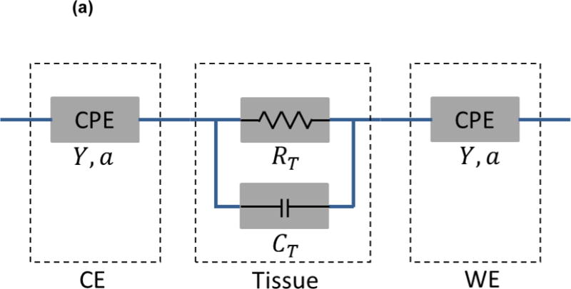
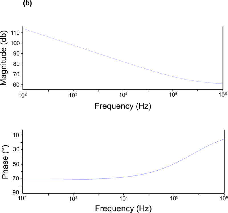
(a) Equivalent circuit diagram for the paired electrode sensor. a: constant between 0 and 1, corresponding to non-ideal interface effects between electrodes and tissues. CE: counter electrode. WE: working electrode. CPE: constant phase element. Y: nominal capacitance value. RT: resistive element. CT: capacitive element. (b) The Bode plot for the equivalent circuit model with component values: Y=100nS. RT=1kΩ. CT=10pF. a=0.8.
Animal studies
All animal studies were performed in compliance with the IACUC protocol approved by the UCLA Office of Animal Research. Rabbit experiments were conducted in the UCLA translational research imaging center (TRIC) lab. Analyses were conducted in n=5 control rabbits fed a chow diet and n=3 age-matched high-fat fed NZW male rabbits26. High-fat animals were placed on a 1.5% cholesterol and 6.0% peanut oil diet (Harlan laboratory) for 9 weeks prior to harvesting. Animals were anesthetized with isofluorane gas, endotracheally intubated and placed on a mechanical ventilator. Blood pressure and heart rate were monitored continuously by a non-invasive paw cuff as well as an intra-arterial sensor. A femoral cut-down was performed and a 4-French arterial sheath placed in the common femoral artery. Under fluoroscopic guidance (Siemens Artis Zeego with robotic arm) and iodinated contrast dye injection, the EIS sensor was advanced to the abdominal aorta for live interrogation. In vivo and ex vivo measurements were obtained in the abdominal aorta between the renal artery bifurcation and also proximal to the aortic bifurcation. Following animal harvesting, ex vivo measurements were conducted in various segments with differing levels of lipid burden in the descending thoracic aorta and abdominal aorta at the level of the renal arteries. Three replicates were performed at each interrogation site. Thus, for each animal, measurements were obtained at 3 anatomic sites: 1. descending thoracic aorta, 2. abdominal aorta at the level of the renal arteries, and 3. abdominal aorta proximal to the aortic bifurcation. In the high-fat fed animals, these 3 anatomic sites correspond to areas with: 1. severe plaque, 2. moderate plaque, and 3. mild plaque, respectively. AC signals with peak-to-peak voltages of 50 mV and frequencies ranging from 1000 Hz to 300 kHz were delivered at each site. The impedance magnitude and the phases of the impedances were acquired at 10 data points per frequency decade.
EIS measurements in aortas
Angiograms were obtained during fluoroscopy to document vessel anatomy and verify appropriate advancement of the EIS sensor. Measurements were obtained in control rabbit aortas and in various segments of the high-fat fed rabbit aortas. Different anatomical segments exhibited varying degrees of atherosclerosis, with the most prominent being the thoracic aorta. Segments that were analyzed were the descending thoracic aorta (severe plaque), abdominal aorta at the level of the renal artery bifurcation (moderate plaque), and abdominal aorta proximal to the aortic bifurcation (mild plaque). Results were compared to plaque burden as assessed by lipid content and inflammatory activation by macrophage. The catheter-based balloon-inflatable EIS sensor was deployed in vivo. The balloon was inflated to 10 psi (pounds per square inch) to allow for optimal endoluminal contact.
Microfabrication and deployment of high-frequency IVUS
PbMg1/3Nb2/3O3-PbTiO3 (PMN-PT) single crystal, with its superior piezoelectric properties, served as the functional element of the IVUS transducer used in this study19. The general fabrication process previously reported was modified to fabricate the four-layered IVUS transducer23. The IVUS transducer was then inserted into customized probe housing (a stainless steel tube one window; OD: 1 mm; length: 2 mm). The coaxial cable was covered by the flexible torque coil to ensure accurate and smooth translation of torque to the distal end over a large distance and through tortuous curves. During experiments, the probe was inserted into a sheath to avoid cross-contamination between probe and arterial segments. Saline solution was filled in the sheath before experiments. For the IVUS imaging system, a Panametrics PR5900 pulser/receiver (Olympus NDT, Kennewick, WA) was used for pulse generation and signal detection with 26 dB gain and 10~100 MHz band-pass filter. The ultrasonic radio frequency data was fed into the 12 bit digitizer and digitized at a sampling rate of 400 MHz. The acquired IVUS signal was processed, displayed and saved simultaneously by custom built software24. The system has a frame rate of 20 frames per second with 1000 A-lines per frame. A custom built rotary joint device was used for motion control and signal coupling from the rotational part to the stationary part. All these components were fixed to a translational stepper motor with pull-back capability. To evaluate the general performance of the IVUS transducer and imaging system, the pulse-echo testing was performed. The measured center frequency of the IVUS transducer was 39 MHz with a fractional bandwidth of 45%.
Histology
A portion of each aorta was fixed in 4% paraformaldehyde, embedded in paraffin and serially sectioned at 5 μm for histological analyses. Lipids were identified by hematoxylin and eosin staining and macrophages by F4/80 staining (monoclonal rat anti-mouse antibody, Invitrogen).
Statistical and correlation analyses
Statistical analysis was performed using analysis of variance with multiple comparisons adjustment for this study design. Since the assumption of homogeneity of variance was violated as evidenced by a significant Levene’s test18 in most cases, the Brown-Forsythe test2 was systematically used to determine significance across groups. Dunnett’s test9 was used for multiple comparisons given this statistical approach does not depend on homogeneity of variances and corrects for multiple testing. IBM SPSS version 20 was used to perform the analysis. A P-value < 0.05 was considered significant. Spearman’s correlation was determined as follows:
| (4) |
where r = Spearman correlation, di = difference between ranks, n = sample size.
RESULTS
EIS measurements by the 2-point configuration
The catheter-based balloon-inflatable 2-point configuration was deployed in vivo. The frequency sweep revealed similar impedance profiles in the frequency range 1 – 10 kHz, consistent with a more resistive pattern in tissues (Fig. 3a). However, significant differences in impedance appeared in the frequency range 10 – 300 kHz, consistent with a more capacitive behavior of the arteries (P < 0.05, Brown-Forsythe test). The EIS measurements revealed a baseline impedance of 12 kΩ at 10 kHz, 5.6 kΩ at 100 kHz, and 5.2 kΩ at 300 kHz in control arteries. EIS increased in the presence of oxLDL-rich lesions. At an intermediate frequency of 10 kHz, the magnitude of the impedance increased to 12.5 kΩ, 13 kΩ and 14 kΩ in the abdominal aorta with mild plaque, the abdominal aorta at the renal artery bifurcation with moderate plaque and the descending thoracic aorta with severe plaque, respectively. At a high frequency of 300 kHz, the magnitude of the impedance increased further to 5.9 kΩ, 7 kΩ and 8.4 kΩ in arterial segments with mild, moderate and severe plaque, respectively. As a corollary, a decrease in phase was observed in the lower frequency range, indicating a longer delay between voltage input and current output which progressively increased in the higher frequency range (P < 0.05 from 1.5 – 125 kHz, Brown-Forsythe test) (Fig. 3b). Ex vivo studies were conducted in explanted aortic segments, demonstrating a high correlation with in vivo measurements with a Spearman r = 0.9732 (P < 0.0001) (Fig. 3c). Thus, the 2-point configuration allowed for EIS measurements to quantify the degrees of plaque burden.
Figure 3.
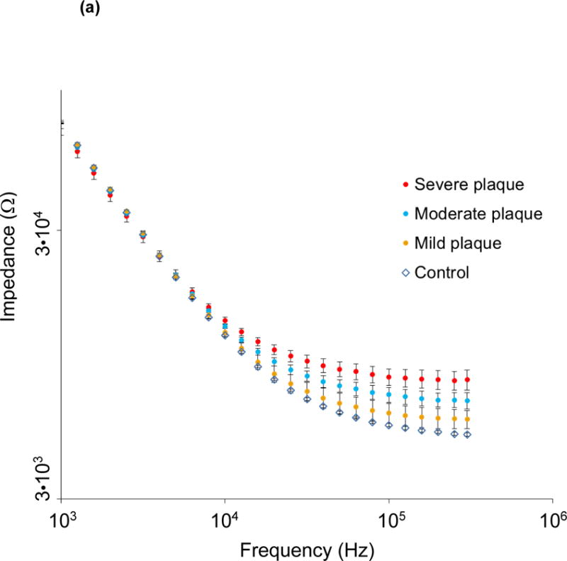
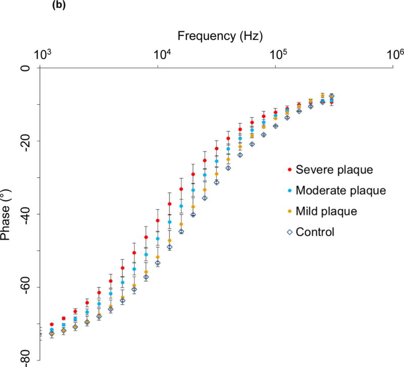
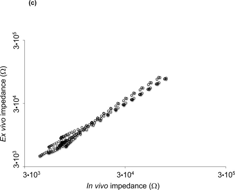
(a) Impedance magnitude in control aortas and aortic segments with mild, moderate and severe plaque are depicted in logarithmic scale. P < 0.05 in the frequency range 10 – 300 kHz for impedance profiles, Brown-Forsythe test. Data presented as means ± standard errors of the mean. (b) Phase spectra in control aortas and aortic segments with mild, moderate and severe plaque are depicted in logarithmic scale. P < 0.05 in the frequency range 1.5 – 125 kHz for phase spectra, Brown-Forsythe test. Data presented as means ± standard errors of the mean. (c) In vivo vs. ex vivo correlation of impedance spectra obtained from identical aortic segments with the EIS sensor. Spearman test r = 0.9732, P < 0.0001.
Validation with intravascular ultrasound (IVUS) and immunohistochemistry
To validate the EIS measurements, we performed IVUS and histology to assess the underlying atherosclerotic lesions. Visualization of atherosclerotic plaques of varying burden was performed by IVUS to confirm underlying plaque severity (Fig. 4a, b). The IVUS and EIS measurements were not obtained simultaneously, but sequentially with different catheters to avoid interference between the two transducers. Atherosclerotic plaques were further identified by hematoxylin and eosin (H & E) staining, and the oxLDL-laden macrophage/foam cells were detected by F4/80 immunohistochemistry staining (Fig. 4c–j) to support the elevated EIS values (Fig. 3a). Control aortas were free of oxLDL-rich lesions or macrophages, validating the low EIS values (Fig. 3a).
Figure 4.
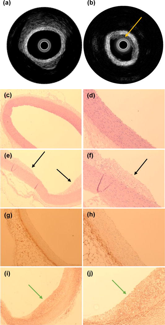
Example of intravascular ultrasound measurements obtained in a control aorta (a) and from a segment with atherosclerotic plaque (b). The yellow arrow is pointing towards the atherosclerotic plaque. Histologic analysis of control aortas at 4× (c) and 10× (d) magnification demonstrate absence of subendothelial lipid deposits, whereas subendothelial lipid content characteristic of plaques in atherosclerotic lesions (black arrows) are readily identified in animals fed a high fat diet at 4× (e) and 10× (f). Immunohistochemical analysis of macrophage infiltration demonstrates their absence in control aortas at 4× (g) and 10× (h) whereas a robust presence (green arrows) is documented in atherosclerotic aortic segments from animals fed a high fat diet at 4× (i) and 10× (j). Yellow arrows: plaque identified by IVUS. Black arrow: plaque identified by histology. Green arrows: macrophages identified by immunohistochemistry.
EIS measurements of epicardial fat tissue in comparison with aortic segments
To further characterize the 2-point configuration, we obtained EIS measurements from ex vivo epicardial fat tissue and compared these to aortic segments (Fig. 5). No differences were observed in epicardial fat tissue between control and high fat fed animals. Impedance profiles were significantly higher in epicardial fat tissue compared to aortic segments throughout the frequency sweep from 1 kHz – 300 kHz (P < 0.05, Brown-Forsythe test). Post-hoc multiple testing analyses further illustrated significant differences between control aortas and combined atherosclerotic plaque segments from 10 – 300 kHz (P < 0.05, Dunnett test). These findings corroborate the capability of the simplified 2-point configuration to distinguish tissues exhibiting varying lipid burden by intravascular EIS measurements.
Figure 5.
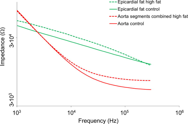
Representation of combined EIS impedance spectra from aortas and epicardial fat. Control aortas, atherosclerotic aortas displayed as the mean value of all analyzed segments from various levels of the arterial tree and superimposed profiles of epicardial fat tissue demonstrate stark contrasts in EIS profiles and tissue impedance signatures across the frequency sweep. P < 0.05 throughout the frequency sweep from 1 kHz – 300 kHz in epicardial fat tissue compared to aortic segments, Brown-Forsythe test. P < 0.05 between control aortas and combined atherosclerotic plaque segments in the frequency range 10 – 300 kHz, Dunnett test.
Two-point electrode configuration
One of the critical issues for the 4-point EIS design is the existence of the negative sensitivity field13. The formulation of the sensitivity field (S) of a tetrapolar configuration has been detailed in previous works12 and can be written as
| (5) |
where J1 and J2 are the current density at the current injection electrode pair and the voltage measuring electrode pair, respectively, and I denotes the actual current being injected.
As seen in Eq. 5, the dot product of J1 and J2 can possibly become a negative value in certain regions of the targeted tissue, indicating a reverse correlation between the local conductivity change within the tissue and the overall impedance value. Consequently, the impedance measurement can no longer genuinely represent the real local conductivity variation and thus fails to recognize regions of different plaque severity. Once shifted to a 2-point design, J1 and J2 represent the same current density flowing across the two electrodes in use and the dot product between the two will always remain positive.
We have highlighted characteristics of EIS sensors with different numbers of electrodes in Table 1, and illustrate lower maximum relative variability (defined as standard deviation/mean), an indicator of higher SNR, with the current sensor design. Compared to the concentric design, the 2-point configuration generated a higher SNR for its high common mode rejection ratio (CMRR) as a result of symmetrical electrode-tissue contact area. In addition, under the same input current, the electrode pair with larger separation (2-point) provides a higher electrical potential (higher resistivity due to larger dimension) allowing penetration into the deeper tissues with robust signals, rendering the data more reliable. We compare the previous concentric design with the current design in terms of input voltage, sweeping frequency, impedance and maximum relative variation in Table 2. EIS by 2-point configuration was most sensitive in detecting vascular tissue compositions at 10 – 300 kHz while the concentric bipolar configuration was sensitive at 100–300 kHz.
Table 1.
Comparison of EIS sensors with different numbers of electrodes. Maximum relative variability: standard deviation/mean.
Table 2.
Comparison of different 2-point EIS sensors. Maximum relative variability: standard deviation/mean.
The 2-point design further reduces the number of unknown variables from 6 to 4 in the equivalent circuit36, reducing simulation and calculation. The 4 unknown variables required in both the 2-point and concentric bipolar designs are: 1) resistive and 2) capacitive elements of the tissue as represented by: RT and CT, the constant phase element of the electrode-tissue interface in the counter electrode , where 3) Y denotes the nominal capacitance value, and 4) a the constant of the surface property of the electrodes ranging from 0 to 1 corresponding to non-ideal interface effects. The additional 2 unknowns specific to the previous concentric design are 1) double layer capacitance cdl2 and 2) charge transfer resistance, RCT2, both arising from working electrode-tissue interface.
DISCUSSION
The main contribution to endoluminal assessment of atherosclerotic plaque we present is the design and fabrication of balloon inflatable 2-point electrodes for EIS measurements of oxLDL-rich plaque. We characterize the stretchable sensors in terms of distinct changes in impedance and phase spectra in response to balloon inflation pressure. Our 2-point approach represents an advancement to the previously proposed linear 4-point electrode arrays28, 29, 30, which preclude detection of small and non-homogeneous lesions. Thus, we demonstrate a simplified 2-point electrode configuration to advance the electrochemical impedance measurements for intraplaque lipid-laden lesions.
Atherosclerosis is a chronic inflammatory disease with involvement of both innate and adaptive immune pathways21. The atherosclerotic plaque involves a complicated interplay between lipid metabolism, inflammation, macrophage activation and collagen breakdown, and the rupture of atherosclerotic plaques remains a leading cause of mortality in developed countries20. Currently, fractional flow reserve (FFR), IVUS or optical coherence tomography (OCT) are limited to anatomic and hemodynamic characteristics of atherosclerotic plaques1. Despite the advent of computerized tomographic (CT) angiography, high resolution magnetic resonance imaging (MRI)31, intravascular ultrasound (IVUS), near-infrared fluorescence (NIRF)15, and time-resolved laser-induced fluorescence spectroscopy25, real-time interrogation of metabolically active, lipid-rich plaques remains an unmet clinical need. However, none of the above modalities assess intraplaque lipid and oxidized LDL content as has been proposed with EIS. Importantly, oxidized low density lipoprotein (oxLDL) induces transformation of macrophages to lipid-laden foam cells3. Furthermore, growing evidence supports that oxLDL and thin-cap fibroatheromas (TCFA) rich in macrophage/foam cells are prone to mechanical stress and destabilization8, 11, 37. Others and our group have further demonstrated the hemodynamic shear forces on metabolically active lesions in athero-prone regions32, 36. The safety and relatively simple deployment of an invasive EIS sensor merit further consideration in experimental and translational studies, either alone or combined with other invasive modalities such as IVUS.
When comparing our 2-point sensor with previous 3-point and 4-point linear arrays (Table 1), the maximum relative variability was higher (i.e. more variability and hence less stable EIS results) by 50% in 3-point sensors and by 150% in 4-point sensors. In addition, when comparing our linear 2-point sensor with the concentric bipolar electrodes (Table 2), the maximum relative variability was the same, however the major advances of the current 2-point design allow for deep tissue penetration for intraplaque burden assessment (Fig. 1b). The spacing between the two concentric electrodes was 100 μm, confining current traveling to the fibrous cap area; whereas the spacing between the 2-point round electrodes is 400 μm, allowing for deep current penetration in the frequency band 10 – 100 kHz with high SNR.
Also, the contact impedance between the two concentric bipolar electrodes varies due to the different electrode area, giving rise to different voltage drops at each double layer and introducing common mode noise into the detected signal. This reduction in noise rejection capacity results in a decrease in SNR. Moreover, the 2-point design reduced the unknown variables from 6 for the concentric bipolar electrodes to 4 as simulated by the equivalent circuit (Fig. 2).
Our flexible and 2-point electrodes were mounted on an inflatable balloon for endoluminal EIS quantification of lipid burden. EIS quantifies the intrinsic electrochemical properties of tissues; namely water content, electrolyte concentration, vascular calcification and cholesterol/lipid content which influence the changes in impedance. Sites of mild, moderate and severe atherosclerotic plaque burden in previously described specific segments of the aorta16 were verified by fluoroscopy and IVUS for gross anatomy, by histology for lipid presence, and by immunohistochemistry for foam cells or macrophages. We applied AC current to the lesions and recorded impedance, Z, to determine electrochemical properties. EIS takes advantage of the vascular tissues that store and dissipate charges4, 34, 35, 36. In addition to the capability of EIS to differentiate oxLDL-rich from oxLDL-free lesions34, 35 we further demonstrated that endoluminal EIS signals are independent of blood viscosity and flow rate as evidence by the high Spearman correlation between in vivo and ex vivo EIS signals (Fig. 3c). Of note, the overall 3D geometry of vessels undergoes changes due to the loss of residual stresses during resection, leading to some modification in the endoluminal area over which stretchable sensor apposition was performed and impedance interrogation conducted. Despite this limitation, we observed a highly significant correlation between in vivo and ex vivo measurements. EIS signals of epicardial fat with a distinct impedance spectrum further support our 2-point design to quantify lipid-rich tissues.
Intravascular EIS assessment by deployment of linear 4-point microelectrode array (2 cm long) via balloon catheter was demonstrated in NZW rabbits17, 28, 30. To address EIS signals in human coronary arteries, we previously designed concentric microelectrodes (300 μm in diameter) that were conformal to the non-planar endoluminal surface and non-uniform electric current distribution. Distinct from the large surface area of the 4-point design, the concentric bipolar microelectrodes afforded a 2,000-fold reduction in size for intravascular deployment in the mice and rabbit models36. To further simplify the concentric bipolar design for EIS interrogation in humans, we have re-configured to a 2-point, paired electrode design (highlighted in Fig. 1a). Compared to the concentric design4, 2-point configuration provides a larger separation between the electrode pair (400 μm), allowing for deep current traveling into the intraplaque lipid core to achieve significant tissue impedance disparities. Moreover, these symmetric electrode pairs provide a common mode rejection capability to reject the unwanted input signals from the wanted difference signals.
The gold paired electrodes are well embedded in a layer of insulating PAC film to minimize current drift and cross-talks (Fig. 1). The limited exposed areas for endoluminal contact circumvent potential short circuit. The EIS measurement is conducted at room temperature within the operating range in the Gamry system (0~70 °C) to prevent current drifts. To predict the potential cross-talk (parasitic capacitance), we performed the open circuit impedance, ZP, measurement between the two metal wires to have a quantitative estimation of the potential parasitic capacitance CP. ( ; see Fig. 6). Impedance values arising from the parasitic capacitance is on the order of 10 kOhm at ~300 kHz in comparison with the measured tissue impedance of 1 kOhm at ~300 kHz. For this reason, the equivalent impedance of parasitic capacitance is 10 times the measurement impedance, minimizing current drift and cross-talk under physiologic conditions.
Figure 6.
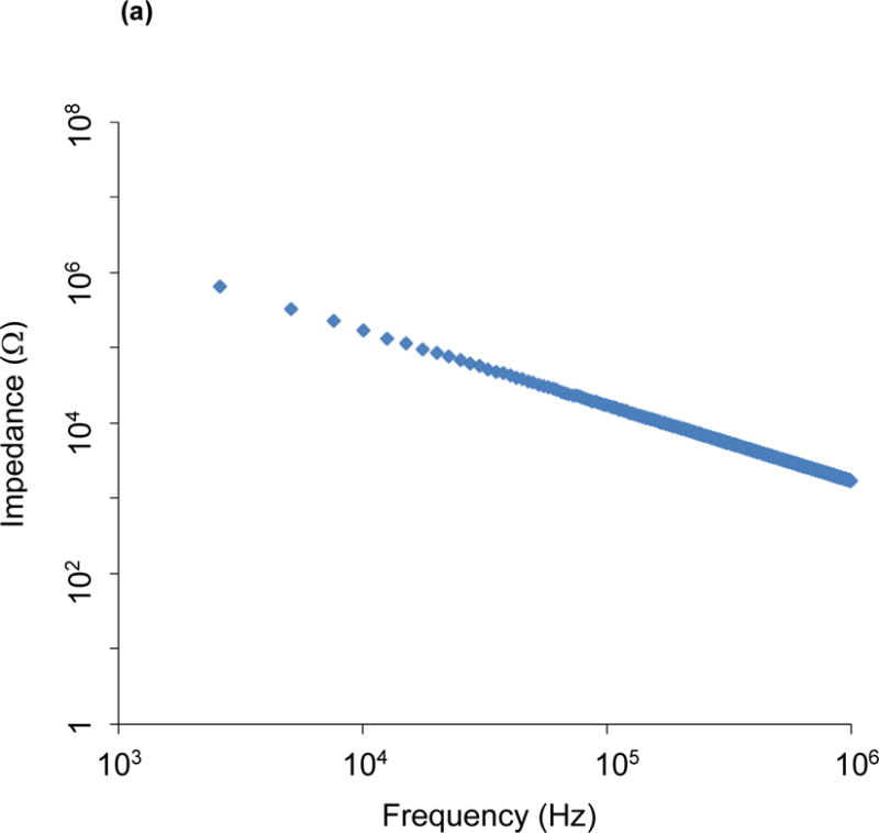
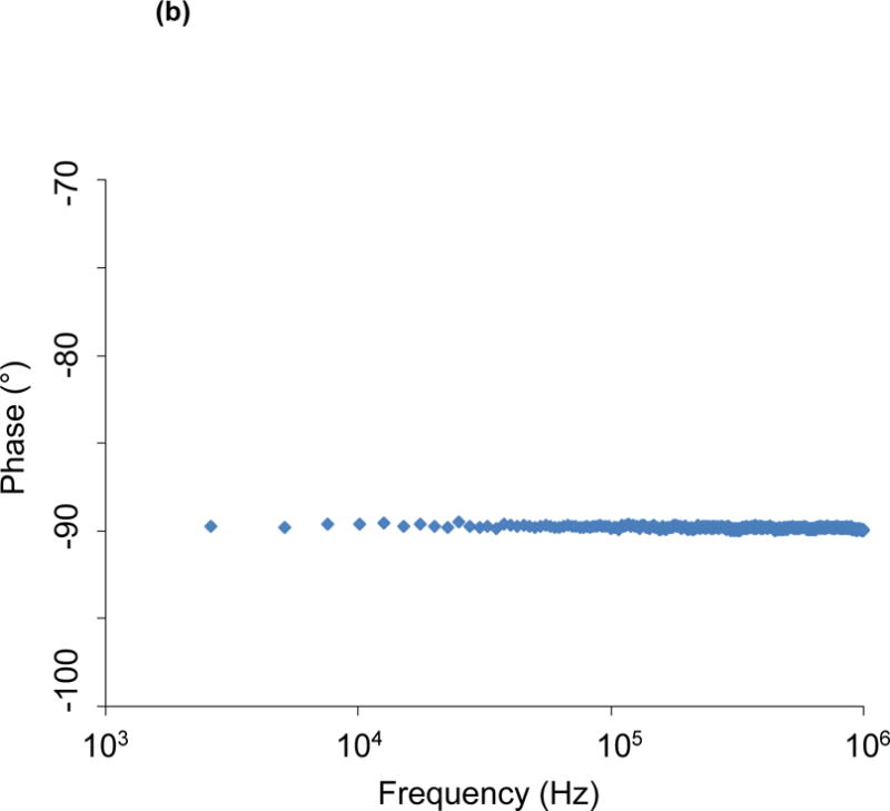
Open circuit measurement of impedance magnitude (a) and phase spectra (b) between the two metal wires allows a quantitative estimation of the potential parasitic capacitance. Impedance values arising from the parasitic capacitance are on the order of 10 kOhm at 300 kHz.
The high-frequency range indicates that real-time EIS quantification with the decreased phase delay supports the reliable intravascular strategy. An inductor circuit was used for voltage application and subsequent current generation to quantify plaque burden. When inductors (or capacitors) are involved in an AC circuit, the peaks in voltage and current are not synchronized. The fraction of a period difference between the peaks expressed in degrees is the phase difference of ≤ 90°. Our data indicate that there was a significant phase delay of ~ −70° in the low frequency range and a decrease in phase delay to ~ −10° in the highest frequencies. As a result, high frequency range shortens the duration of time lag between voltage application and current generation. The EIS impedance profiles obtained were significantly different over the 10 – 300 kHz frequency sweep, with high impedance in the severe plaque area of the descending thoracic aorta, intermediate impedance in the moderate plaque area of the proximal abdominal aorta, and low impedance in the mild plaque area of the distal abdominal aorta. These results support the application of EIS to quantify intraplaque lipid burden in real time. Previous histological analysis of aortic atherosclerosis in the rabbit model agreed with severe, moderate, and mild degrees of lipid burden in the thoracic, proximal abdominal and distal abdominal aorta, respectively16.
Flexible electronics is an emergent intravascular approach for pre-clinical models. Surface flexible hybrid electronics embedded in Polydimethylsiloxane (PDMS) and adhered to the skin have been tested for electrocardiogram and temperature monitoring33. Implantable flexible electrode arrays have been embedded in Parylene C (PAC) for its bio-compatibility6 and investigated for retina implants to restore vision7. We have quantified the Young’s modulus, or elastic modulus, defined as the ratio of stress to strain of the stretchable paired microelectrodes mounted on inflatable balloons4. Since the Young’s modulus of nylon for the balloon is 2.7~4.8 GPa14, matching with that of PAC (3.2 GPa)22 to minimize strain mismatch, the 2-point electrodes affixed onto the non-compliant balloon (Venture Medical, USA) withstood the inflated balloon at 10 pounds per square inch (psi) or ~69 KPa for optimal endoluminal contact. In fact, the applied stress at 10 psi was well below the tensile stress at 58 MPa of PAC. Furthermore, the Young’s modulus of the blood vessel ranges from 0.2 – 0.6 MPa10 resulting in < 35% deformation in the normal direction of blood flow. Thus, the flexible and stretchable 2-point design provides safe endoluminal contact.
Our 2-point sensor discriminates areas with no plaque (controls), mild plaque (abdominal aorta proximal to the aortic bifurcation), moderate plaque (abdominal aorta at the level of the renal arteries) and severe plaque (descending thoracic aorta), thereby detecting by EIS observations previously made by histology in experimental rabbits16. In humans, the intravascular assessment of coronary arteries with differing levels of intraplaque lipid burden has reached clinical use1. Additional studies in humans have established that plaques with larger lipid and oxLDL area are more prone to vulnerability and rupture with ensuing clinical events such as myocardial infarction11. These comparisons with pathology observations in humans provide the basis for future studies to establish the ability of EIS to distinguish stable from vulnerable atherosclerotic plaques.
In conclusion, the 2-point EIS design represents a diagnostic and preventive strategy to identify lipid-rich plaques for targeted therapy and for longitudinal follow-up in response to pharmacological intervention. We demonstrate a new generation of balloon-inflatable 2-point microelectrodes as a simple, reliable, safe and robust approach to complement diagnostic angiography. Our findings provide a basis for future pre-clinical studies to determine the EIS sensor either as a stand-alone catheter or packaged with other modalities such as IVUS1.
Acknowledgments
The present work was funded by National Institutes of Health grants HL118650 (T.K.H.), HL083015 (T.K.H.), HD069305 (T.K.H.), HL111437 (T.K.H.), T32HL007895 (R.R.S.P.) and the UCLA STAR program (R.R.S.P.).
Footnotes
DISCLOSURES
The authors have no conflict of interest to disclose.
References
- 1.Bourantas CV, Garcia-Garcia HM, Naka KK, Sakellarios A, Athanasiou L, Fotiadis DI, Michalis LK, Serruys PW. Hybrid intravascular imaging: current applications and prospective potential in the study of coronary atherosclerosis. J Am Coll Cardiol. 2013;61:1369–1378. doi: 10.1016/j.jacc.2012.10.057. [DOI] [PubMed] [Google Scholar]
- 2.Brown MB, Forsythe AB. Robust tests for equality of variances. J Am Stat Assoc. 1974;69:364–367. [Google Scholar]
- 3.Brown MS, Goldstein JL. Lipoprotein metabolism in the macrophage: implications for cholesterol deposition in atherosclerosis. Annu Rev Biochem. 1983;52:223–261. doi: 10.1146/annurev.bi.52.070183.001255. [DOI] [PubMed] [Google Scholar]
- 4.Cao H, Yu F, Zhao Y, Scianmarello N, Lee J, Dai W, Jen N, Beebe T, Li R, Ebrahimi R, Chang DS, Mody FV, Pacella J, Tai YC, Hsiai T. Stretchable electrochemical impedance sensors for intravascular detection of lipid-rich lesions in New Zealand White rabbits. Biosens Bioelectron. 2014;54:610–616. doi: 10.1016/j.bios.2013.11.059. [DOI] [PMC free article] [PubMed] [Google Scholar]
- 5.Castellanos A, Ramos A, González A, Green NG, Morgan H. Electrohydrodynamics and dielectrophoresis in microsystems: scaling laws. J Phys D Appl Phys. 2003;36:2584–2597. [Google Scholar]
- 6.Chang JH, Huang R, Tai YC. High-density 256-channel chip integration with flexible parylene pocket. IEEE 16th International Conference on Solid-State Sensors, Actuators and Microsystems. 2011:378–381. [Google Scholar]
- 7.Chang JH, Liu Y, Kang D, Tai YC. Reliable packaging for parylene-based flexible retinal implant. IEEE 17th International Conference on Solid-State Sensors, Actuators and Microsystems. 2013:2612–2615. [Google Scholar]
- 8.Chinetti-Gbaguidi G, Baron M, Bouhlel MA, Vanhoutte J, Copin C, Sebti Y, Derudas B, Mayi T, Bories G, Tailleux A, Haulon S, Zawadzki C, Jude B, Staels B. Human atherosclerotic plaque alternative macrophages display low cholesterol handling but high phagocytosis because of distinct activities of the PPARgamma and LXRalpha pathways. Circ Res. 2011;108:985–995. doi: 10.1161/CIRCRESAHA.110.233775. [DOI] [PMC free article] [PubMed] [Google Scholar]
- 9.Dunnett CW. A multiple comparison procedure for comparing several treatments with a control. J Am Stat Assoc. 1955;50:1096–1121. [Google Scholar]
- 10.Ebrahimi AP. Mechanical properties of normal and diseased cerebrovascular system. J Vasc Interv Neurol. 2009;2:155–162. [PMC free article] [PubMed] [Google Scholar]
- 11.Ehara S, Ueda M, Naruko T, Haze K, Itoh A, Otsuka M, Komatsu R, Matsuo T, Itabe H, Takano T, Tsukamoto Y, Yoshiyama M, Takeuchi K, Yoshikawa J, Becker AE. Elevated levels of oxidized low density lipoprotein show a positive relationship with the severity of acute coronary syndromes. Circulation. 2001;103:1955–1960. doi: 10.1161/01.cir.103.15.1955. [DOI] [PubMed] [Google Scholar]
- 12.Geselowitz DB. An application of electrocardiophic lead theory to impedance plethysmography. IEEE Trans Bio-Med Eng. 1971;18:38–41. doi: 10.1109/tbme.1971.4502787. [DOI] [PubMed] [Google Scholar]
- 13.Grimnes S, Martines ØG. Sources of error in tetrapolar impedance measurements on biomaterials and other ionic conductors. Sources of error in tetrapolar impedance measurements on biomaterials and other ionic conductors. J Phys D: Appl Phys. 2007;40:9. [Google Scholar]
- 14.Fakirov S, Evstatiev M, Petrovich S. Microfibrillar reinforced composites from binary and ternary blends of polyesters and nylon 6. Macromolecules. 1993;26:5219–5226. [Google Scholar]
- 15.Jaffer FA, Vinegoni C, John MC, Aikawa E, Gold HK, Finn AV, Ntziachristos V, Libby P, Weissleder R. Real-time catheter molecular sensing of inflammation in proteolytically active atherosclerosis. Circulation. 2008;118:1802–1809. doi: 10.1161/CIRCULATIONAHA.108.785881. [DOI] [PMC free article] [PubMed] [Google Scholar]
- 16.Koike T, Liang J, Wang X, Ichikawa T, Shiomi M, Sun H, Watanabe T, Liu G, Fan J. Enhanced aortic atherosclerosis in transgenic Watanabe heritable hyperlipidemic rabbits expressing lipoprotein lipase. Cardiovasc Res. 2005;65:524–534. doi: 10.1016/j.cardiores.2004.10.022. [DOI] [PubMed] [Google Scholar]
- 17.Konings MK, Mali WP, Viergever MA. Development of an intravascular impedance catheter for detection of fatty lesions in arteries. IEEE Trans Med Imaging. 1997;16:439–446. doi: 10.1109/42.611353. [DOI] [PubMed] [Google Scholar]
- 18.Levene H. Robust tests for equality of variances. In: Olkin I, Hotelling H, et al., editors. Contributions to probability and statistics: essays in honor of Harold Hotelling. Stanford University Press; 1960. pp. 278–292. [Google Scholar]
- 19.Li X, Ma T, Tian J, Han P, Zhou Q, Shung KK. Micromachined PIN-PMN-PT crystal composite transducer for high-frequency intravascular ultrasound (IVUS) imaging. IEEE Trans Ultrason Ferroelectr Freq Control. 2014;61:1171–1178. doi: 10.1109/TUFFC.2014.3016. [DOI] [PMC free article] [PubMed] [Google Scholar]
- 20.Libby P. Mechanisms of acute coronary syndromes and their implications for therapy. N Engl J Med. 2013;368:2004–2013. doi: 10.1056/NEJMra1216063. [DOI] [PubMed] [Google Scholar]
- 21.Libby P, Lichtman AH, Hansson GK. Immune effector mechanisms implicated in atherosclerosis: from mice to humans. Immunity. 2013;38:1092–1104. doi: 10.1016/j.immuni.2013.06.009. [DOI] [PMC free article] [PubMed] [Google Scholar]
- 22.Lin JCH, Lam G, Tai YC. Viscoplasticity of parylene-C film at body temperature. IEEE 25th International Conference on Micro Electro Mechanical Systems. 2012:476–479. [Google Scholar]
- 23.Ma T, Zhang X, Chiu CT, Chen R, Kirk Shung K, Zhou Q, Jiao S. Systematic study of high-frequency ultrasonic transducer design for laser-scanning photoacoustic ophthalmoscopy. J Biomed Opt. 2014;19:16015. doi: 10.1117/1.JBO.19.1.016015. [DOI] [PMC free article] [PubMed] [Google Scholar]
- 24.Ma T, Yu M, Li J, Munding CE, Chen Z, Fei C, Shung KK, Zhou Q. Multi-frequency intravascular ultrasound (IVUS) imaging. IEEE Trans Ultrason Ferroelectr Freq Control. 2015;62:97–107. doi: 10.1109/TUFFC.2014.006679. [DOI] [PMC free article] [PubMed] [Google Scholar]
- 25.Marcu L, Fishbein MC, Maarek JM, Grundfest WS. Discrimination of human coronary artery atherosclerotic lipid-rich lesions by time-resolved laser-induced fluorescence spectroscopy. Arterioscler Thromb Vasc Biol. 2001;21:1244–1250. doi: 10.1161/hq0701.092091. [DOI] [PubMed] [Google Scholar]
- 26.Pelias MZ. Classics in arteriosclerosis research: On experimental cholesterin steatosis and its significance in the origin of some pathological processes by N. Anitschkow and S. Chalatow, 1913. Arteriosclerosis. 1983;3:178–182. [PubMed] [Google Scholar]
- 27.Sevanian A, Hwang J, Hodis H, Cazzolato G, Avogaro P, Bittolo-Bon G. Contribution of an in vivo oxidized LDL to LDL oxidation and its association with dense LDL subpopulations. Arterioscler Thromb Vasc Biol. 1996;16:784–793. doi: 10.1161/01.atv.16.6.784. [DOI] [PubMed] [Google Scholar]
- 28.Streitner I, Goldhofer M, Cho S, Thielecke H, Kinscherf R, Streitner F, Metz J, Haase KK, Borggrefe M, Suselbeck T. Electric impedance spectroscopy of human atherosclerotic lesions. Atherosclerosis. 2009;206:464–468. doi: 10.1016/j.atherosclerosis.2009.03.015. [DOI] [PubMed] [Google Scholar]
- 29.Streitner I, Goldhofer M, Cho S, Kinscherf R, Thielecke H, Borggrefe M, Suselbeck T, Streitner F. Cellular imaging of human atherosclerotic lesions by intravascular electric impedance spectroscopy. PloS one. 2012;7:e35405. doi: 10.1371/journal.pone.0035405. [DOI] [PMC free article] [PubMed] [Google Scholar]
- 30.Suselbeck T, Thielecke H, Kochlin J, Cho S, Weinschenk I, Metz J, Borggrefe M, Haase KK. Intravascular electric impedance spectroscopy of atherosclerotic lesions using a new impedance catheter system. Basic Res Cardiol. 2005;100:446–452. doi: 10.1007/s00395-005-0527-6. [DOI] [PubMed] [Google Scholar]
- 31.Worthley SG, Helft G, Fuster V, Fayad ZA, Shinnar M, Minkoff LA, Schechter C, Fallon JT, Badimon JJ. A novel nonobstructive intravascular MRI coil: in vivo imaging of experimental atherosclerosis. Arterioscler Thromb Vasc Biol. 2003;23:346–350. doi: 10.1161/01.atv.0000053183.08854.a4. [DOI] [PubMed] [Google Scholar]
- 32.Xiao H, Lu M, Lin TY, Chen Z, Chen G, Wang WC, Marin T, Shentu TP, Wen L, Gongol B, Sun W, Liang X, Chen J, Huang HD, Pedra JH, Johnson DA, Shyy JY. Sterol regulatory element binding protein 2 activation of NLRP3 inflammasome in endothelium mediates hemodynamic-induced atherosclerosis susceptibility. Circulation. 2013;128:632–642. doi: 10.1161/CIRCULATIONAHA.113.002714. [DOI] [PMC free article] [PubMed] [Google Scholar]
- 33.Yeo WH, Kim YS, Lee J, Ameen A, Shi L, Li M, Wang S, Ma R, Jin SH, Kang Z, Huang Y, Rogers JA. Multifunctional epidermal electronics printed directly onto the skin. Adv Mater. 2013;25:2773–2778. doi: 10.1002/adma.201204426. [DOI] [PubMed] [Google Scholar]
- 34.Yu F, Dai X, Beebe T, Hsiai T. Electrochemical impedance spectroscopy to characterize inflammatory atherosclerotic plaques. Biosens Bioelectron. 2011a;30:165–173. doi: 10.1016/j.bios.2011.09.007. 2011. [DOI] [PMC free article] [PubMed] [Google Scholar]
- 35.Yu F, Li R, Ai L, Edington C, Yu H, Barr M, Kim ES, Hsiai TK. Electrochemical impedance spectroscopy to assess vascular oxidative stress. Ann Biomed Eng. 2011;39:287–296. doi: 10.1007/s10439-010-0127-y. [DOI] [PMC free article] [PubMed] [Google Scholar]
- 36.Yu F, Lee J, Jen N, Li X, Zhang Q, Tang R, Zhou Q, Kim ES, Hsiai TK. Elevated electrochemical impedance in the endoluminal regions with high shear stress: implication for assessing lipid-rich atherosclerotic lesions. Biosens Bioelectron. 2013;43:237–244. doi: 10.1016/j.bios.2012.12.024. [DOI] [PMC free article] [PubMed] [Google Scholar]
- 37.Zeibig S, Li Z, Wagner S, Holthoff HP, Ungerer M, Bultmann A, Uhland K, Vogelmann J, Simmet T, Gawaz M, Munch G. Effect of the oxLDL binding protein Fc-CD68 on plaque extension and vulnerability in atherosclerosis. Circ Res. 2011;108:695–703. doi: 10.1161/CIRCRESAHA.111.240515. [DOI] [PubMed] [Google Scholar]


