

High-resolution microscopy of hierarchically organized solid gyroid nanostructures sheds light on the underlying dynamic formation process.
Keywords: Lepidoptera, development of nanostructures, chitin, gyroid, x-ray nanotomography, optical structures, biophotonics
Abstract
The formation of the biophotonic gyroid material in butterfly wing scales is an exceptional feat of evolutionary engineering of functional nanostructures. It is hypothesized that this nanostructure forms by chitin polymerization inside a convoluted membrane of corresponding shape in the endoplasmic reticulum. However, this dynamic formation process, including whether membrane folding and chitin expression are simultaneous or sequential processes, cannot yet be elucidated by in vivo imaging. We report an unusual hierarchical ultrastructure in the butterfly Thecla opisena that, as a solid material, allows high-resolution three-dimensional microscopy. Rather than the conventional polycrystalline space-filling arrangement, a gyroid occurs in isolated facetted crystallites with a pronounced size gradient. When interpreted as a sequence of time-frozen snapshots of the morphogenesis, this arrangement provides insight into the formation mechanisms of the nanoporous gyroid material as well as of the intracellular organelle membrane that acts as the template.
INTRODUCTION
Nanostructured materials (that is, forms of matter characterized by spatial patterns on length scales from a few to a few hundreds of nanometers) provide the foundation of current nanotechnology applications. The functionality of these materials frequently mimics or reflects nature’s vast range of nanostructured mono- or multifunctional materials. Among the most visually stunning manifestations of biological nanostructured materials are the structural coloration effects in insects, birds, and plants, including iridescence (1–3), circular polarization (4, 5), brilliant whiteness (6, 7), and antireflection coatings (8). A particularly intriguing nanostructured geometry is the single gyroid, a chiral, highly ordered porous material with network-like topology and cubic symmetry (9). The optical functionality of gyroid materials have been demonstrated in butterfly wing scales (10–15) and in self-assembled (16, 17) and nanofabricated (18, 19) replicas.
Biomimetic approaches use nature’s ingenious design solutions to achieve functional properties. However, beyond the blueprints for nanostructured designs, there is also much potential for biomimicry about the way nature produces structures. If we want to fabricate structures taking inspiration from nature, we need to understand how these structures are made by nature, specifically for gyroid-like geometries. Bottom-up self-assembly strategies based on block copolymer (16, 17) and lipid (20) self-assembly, and top-down nanofabrication methods (16, 18, 19) have been developed for gyroid materials. However, through millions of years of evolution, nature has achieved formation processes for these same geometries with far greater structural control: For example, gyroid-shaped membranes occur in several intracellular membrane organelles across several kingdoms of life (21–23), including endoplasmic reticula in eukaryotic cells (21, 24, 25). In contrast to the synthetic self-assembly routes, where the lattice parameters are restricted to 10 to 90 nm (16, 17, 20), nature achieves a range of 70 to 500 nm (10, 12, 13, 21, 24). Similarly, nature’s ability to create unbalanced bicontinuous membranes [not represented by minimal surfaces but by constant mean curvature surfaces (26)] is only beginning to be matched by synthetic self-assembly (27), similar to the case with other secondary structural features such as chirality (28) or epitaxial orientation. The elucidation of the mechanisms of in vivo biological nanostructure formation is an essential component toward achieving efficient, large-scale nanostructure formation processes in vitro.
How do butterflies form the gyroid nanostructure? The most direct evidence of the formation process would be provided by time-resolved in vivo imaging of the nanostructure growth during metamorphosis. However, real-space in vivo imaging, by its nature restricted to optical microscopy methods, is complicated by the complexity of the organisms and by surrounding optically thick and soft tissue (29–31). Further complications are the resolution [limited by the diffraction limit, unless super-resolution fluorescence microscopy is used (25, 32)], the need to image deep inside tissue, and limited contrast between biological agents and the aqueous environment, which requires biomarkers to enhance local contrast. The next most direct evidence is provided by rearing butterflies in a controlled fashion whereby the development is aborted at specific stages, followed by structural investigations of fixed tissue postmortem, either by confocal microscopy with biomarker-enhanced optical contrast (29) or transmission electron microscopy (TEM) (33, 34). Over the past decades, Ghiradella (30, 33, 35) and others (12, 36) have proposed a formation mechanism for chitinous nanostructures viz. that chitinous cuticle polymerizes in the larval stage of the butterfly pupae, guided by mutual combined folding of the smooth endoplasmic reticulum (SER) and adjacent plasma lipid–protein membranes. Here, we report how, perhaps counterintuitively, electron and x-ray microscopy imaging of the mature solid chitin nanostructure of the Hairstreak butterfly Thecla opisena can shed some light on the dynamics of the gyroid nanostructure formation.
RESULTS
Structural gyroid-like origin of green coloration
T. opisena is a butterfly with an overall size of ~2 cm and is native to Mexico and the Neotropics. The butterfly has two differently colored sides. The upper (dorsal) side of the butterfly wings has bright blue patches on both fore- and hindwings, within a jet-black framing, but the lower (ventral) side is homogeneously green with a small red patch on each hindwing (Fig. 1A).
Fig. 1. Scale lattice and optical properties.
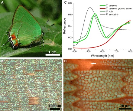
(A) Habitat image of T. opisena (image by P. Brodkin). (B) Scale lattice of the green ventral wing area. (C) Reflectance spectra of the cover (green) and ground [red; arrowhead in (D)] scales of T. opisena and the green scales of Callophrys rubi and Parides sesostris. (D) High-magnification image of a single scale. The scale is green due to an arrangement of the green-colored domains.
Light microscopy of the green ventral side shows the conventional arrangement of scales, with cover scales overlapping rows of differently colored ground scales (Fig. 1B). Remarkably, the cover scales are strongly green, whereas the ground scales are orange-red. Reflectance spectra of the cover scales show a prominent narrow band, with a peak wavelength of ~540 nm, which strongly indicates that the origin of the coloration is structural, whereas the red-peaking spectrum of the ground scales suggests a pigmentary basis (Fig. 1C).
Ultrastructure of nonoverlapping crystallites
High-magnification light microscopy of individual green wing scales shows that the cover scale is not uniformly green, but, instead, exhibits a cellular pattern of distinct nonoverlapping green domains (Fig. 1D). Although a polycrystalline distribution of gyroid domains is observed in several butterfly species (11, 13, 15, 28) and a domain-like structure has been shown before (12, 33), this is the first observation of spatially fully disjoint domains with a strong size gradient along the scale (vide infra).
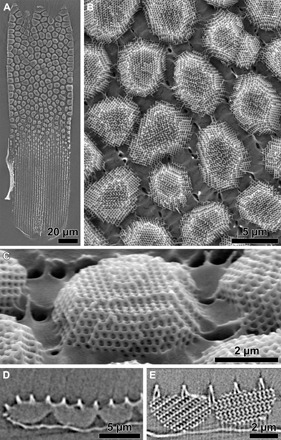
Scanning electron microscopy (SEM) studies of the green scales show that they follow the normal Bauplan of butterfly wing scales: The lower lamina is usually a thin film of chitinous cuticle (37, 38), an abundant polysaccharide in invertebrates, whereas the upper lamina is more elaborate and can be folded in many complex ways (3, 10–13, 28). The upper lamina is usually frontally covered by a set of so-called “ridges,” running parallel to the long side of the scale, connected by “cross-ribs.” The scales of T. opisena follow this design in having a grating of ridges and cross-ribs as the outermost layer that is frontally overlaying a mottled pattern caused by nanostructured crystallites within the scale’s lumen (Fig. 2, A and B). At larger magnification, a striking periodic pattern becomes visible within the crystallites, which is characteristic of the gyroid nanostructure (Fig. 2, C and D); the identification of the internal nanostructure of the crystallites as a single gyroid was further confirmed by x-ray tomography and electron microscopy.
Fig. 2. Ultrastructure of the wing scales.
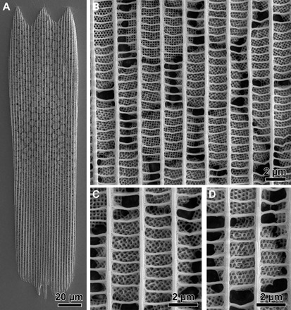
(A) A single wing scale of the green ventral wing area of T. opisena. (B to D) Different high-magnification images of different crystallites. Each crystallite is a single gyroid network.
Difference in pigmentation is suggestive of a two-stage formation process
Previous measurements on butterfly wing scales bearing gyroid-structured photonic crystals demonstrated that pigments, if present, can strongly influence the optical response (10, 13). To interrogate whether pigments are also present in the wing scales of T. opisena, we measured the absorbance of single wing scales immersed in oil, with a refractive index n = 1.56, close to that of dry, chitinous cuticle [(39); Fig. 3A]. Without immersion fluid, individual green domains can be identified (Fig. 1D), but after immersion in refractive index–matching fluid (Fig. 3A), light scattering is strongly suppressed across the visible wavelength range. Where no absorbing pigment is present, the scale is transparent. This is the case for the basal end of the scale, where no gyroid-structured domains are present (Fig. 3B), as well as the interstitial spaces between the domains, where the light still passes through the ridges and the bottom lamina. However, the gyroid-structured domains appear as a mosaic of orange domains, indicating the presence of a blue-absorbing pigment; the measured peak absorbance was ~0.5 at ~430 nm (Fig. 3C).
Fig. 3. Single scale absorbance as evidence for colocalization and two-stage scale formation process.
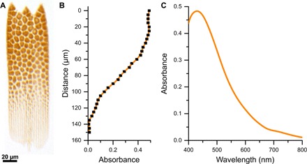
(A) A single cover scale immersed in refractive-index–matching fluid (n = 1.56) shows an orange color, indicating the presence of an absorbing pigment colocalized in the colored domains. (B) Absorbance profile along the central long axis of the scale evaluated at the peak of the (C) absorbance spectrum of the pigment at ~430 nm. Except where the gyroid crystallites are present, the absorbance is negligible, despite the ~200-nm-thick underlying lamella and the porous network in the upper lamina. The origin of the coordinate system for the data presented in panel B is the tip of the scale.
The colocalization of pigment in the domains allows the conclusion that the scale has two different components: the gyroid-structured domains (doped with pigment) and the enveloping cuticle (which is pigment-free and transparent, comprising the lower lamina and the ridges and cross-ribs). The strongly different chemical and structural organization of the two components provides support for Ghiradella’s hypothesis (33) of a two-stage scale development process, where the casing forms first, followed by the building of the internal gyroid structure.
Size analysis of crystallites hints at a time-dependent process
We observe a strong gradient in crystallite size along the long axis of each scale (Figs. 2A and 3A). While the apical area carries large, nearly touching domains, the basal part, where the scale is attached to the wing, is free of crystallites. We analyzed the size distribution and filling fraction of the gyroid crystallites by a multistep Voronoi analysis of 16 index-matched wing scales, each carrying ~100 to 140 crystallites (Fig. 4). The crystallites are largest near the tip of the wing scale (mean area, ~40 μm2; filling fraction, ~0.75) and smallest at the base (mean area, ~20 μm2; filling fraction, ~0.3) (Fig. 4B and fig. S1). The filling fraction, calculated for each crystallite as the area occupied by the crystallite divided by the area of its corresponding Voronoi cell, decreases with distance from the scale tip. The nearest-neighbor distance, defined as the distance between the centers of mass of the Voronoi cells (Fig. 4C), stays approximately constant over the scale with values of ~5 μm. The spatial distribution and size of crystallites within the wing scale are more ordered or uniform than one may expect for a random process, such as random nucleation.
Fig. 4. Voronoi analysis, filling fraction, and size dependence.
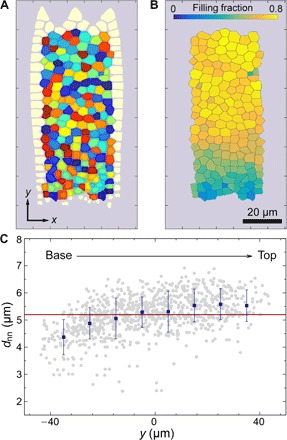
(A) Voronoi analysis of a single wing scale highlighting the different “cells” formed by each crystallite. Cell coloration is arbitrary and only used to distinguish cells. Cells at the wing scale edge, for which Voronoi cells cannot be computed, have been omitted. (B) Filling fraction of each crystallite cell. (C) Nearest-neighbor distance as function of vertical position. The gray points are the nearest-neighbor distances evaluated for individual cells, the blue dots are the averages over all cells within the bands of similar vertical position y and error bars corresponding to SDs, and the red line is a constant fit to the blue data. The origin of the analysis is set to the center of the crystallite area of each individual wing scale. The origin of the analysis is set to the center of the crystallite area of each individual wing scale.
In many butterflies, the wing scale colors are more pronounced at, or even limited to, the tip of the scale, that is, the nonoverlapped exposed scale area (10, 40), indicating an efficient way to produce coloration with minimal material expenditure. In the case of T. opisena, it hints at a time-dependent assembly of the crystallites, with the top crystallites having most time to assemble. We thus assume that the chitinous cuticle intrusion occurs after the formation of the wing scale casing while it is still in a soft form wrapped by the plasma membrane of the cell.
Faceted gyroid crystallites
We have shown above that the adjacent gyroid crystallites are distinctly spaced without mutual contact points and that each crystallite is placed beneath the grid of ridges and cross-ribs (Figs. 2 and 3). To investigate the three-dimensional (3D) shape of these crystallites and their mechanical connections to the surrounding wing-scale casing, we removed the lower lamina of individual wing scales using adhesive tape. The lower lamina is easily removed, whereas the crystallites remain connected to the lattice of ridges and cross-ribs. Figure 5A shows an isolated wing scale upside down with the lower lamina removed.
Fig. 5. Faceted gyroids.
(A) A single wing scale viewed upside down with the lower lamina removed, showing the isolated crystallites. (B) High-magnification image of the upper region of the scale. The porous network of ridges and cross-ribs, below the crystallites, is immersed in the glue of the adhesive tape. (C) Single gyroid crystallites viewed at an inclination of ~50°, revealing their monocrystalline and strongly faceted structure. (D) X-ray tomography cross section showing faceted gyroids. (E) High-resolution x-ray tomography of single crystallites confirms their single crystallinity.
High-magnification SEM images of individual crystallites (Fig. 5B) show that the gyroid crystallites are spatially isolated and that they are not round or cylindrical, but strongly faceted, with the side facing the upper network of cross-ribs and ridges wider than that facing the lower lamina (Fig. 5, B and C, and fig. S2). X-ray tomography of an intact wing scale confirmed the crystallites’ faceted appearance as well as the strong connection of the crystallites to the upper lamina and the minor connectivity to the lower lamina (Fig. 5, C to E, and movies S1 and S2). The thickness of the crystallites, in general, gets smaller as they get closer to the base of the wing scale (Fig. 6 and fig. S1); while the gyroid crystallites are multiple micrometers thick toward the scale tip, close to the base (Fig. 5), single layers of structured chitinous material are observed (Fig. 6A).
Fig. 6. Time-dependent formation mechanism of faceted gyroids.
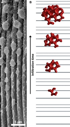
(A) SEM image of the base of a single wing scale of T. opisena. The development has seemingly stopped at different time points. (B) 3D on-view sketch showing the shape invoked by a developing gyroid arrested at different time points.
Single crystallinity, orientation, and chirality of gyroid crystallites
We investigated the degree of single crystallinity of 47 gyroid-structured crystallites resolved in high-resolution x-ray tomographic reconstructions from two different scales, covering smaller domains in a central scale region and bigger domains close to the scale tip (figs. S2 to S4). This analysis was performed by visual inspection of orthogonal slices through the reconstructed grayscale tomography densities, orthogonal to the <100> and <111> directions of each individual domain. For the vast majority (41 domains), each crystallite represented a single ordered gyroid crystal, without visible internal defects (see fig. S5 and the Supplementary Materials).
For each crystallite, we also determined the crystalline orientation relative to the scale surface normal (crystallographic texture). Plotting these orientations in a partial inverse pole figure (fig. S4) shows that the domains exhibited a rather random orientation with respect to the scale normal, albeit a certain prevalence toward the <100> directions is found. Around 15% of the observed crystallites showed the crystallographic [100] direction aligned with the scale surface normal, ~11% with the [110] direction, and ~2% with the [111] direction (to within 10°; see the Supplementary Materials for details). Analysis of the enantiomeric type (chirality) of the gyroid crystallites revealed the coexistence of both enantiomers [as previously described by previous works (12, 15, 28, 41)],with a strong bias for one of the two types and with a ratio of about 3:1 (35:12) between the left- and right-handed gyroids, consistent with previous analyses for C. rubi [see fig. S2 and the Supplementary Materials; statistical null hypothesis testing with significance level of 0.003 (~3σ) rejects the null hypothesis of both enantiomers that are equally probable] (28, 41).
DISCUSSION
The combination of optical microscopy and high-resolution electron and x-ray microscopy has enabled us to observe that the cover scales at the ventral wing sides of T. opisena are filled with disjoint crystallites (Fig. 5) with a pronounced size gradient along the scale (Figs. 2 and 4). The faceted, gyroid-shaped crystallites are loosely connected to the lower lamina (Fig. 5A), and their cuticle composition differs from that of the surrounding network of ridges and cross-ribs and the lower lamina (Fig. 3). The crystallites are single crystalline of varying texture and have a strong bias in chirality, with a ratio of 3:1 of left- to right-handed chirality (Fig. 5).
Our results raise and answer several questions concerning the in vivo development of these structures, for example, what intracellular process forms these structures or what is the dynamic process that creates this complex network. Using TEM images of scales from butterfly chrysalises, Ghiradella (33) described the in vivo development of the gyroid-nanostructured scales of Callophrys gryneus. Each wing scale is the product of a single developing cell, which adopts a highly anisotropic characteristic shape during a time frame of several days, likely through the stretching of an internal F-actin network (Fig. 2A) (29, 31). Ghiradella’s images (33) suggest that the development proceeds in two stages, namely, by the formation of the thin-layered lower lamina and the grating of cross-ribs and ridges of the upper lamina followed by the formation of the internal nanostructure. Our result that only the gyroid crystallites are pigmented and not the surrounding casing strongly suggests that the scales of T. opisena fundamentally consist of two components (Fig. 3). Furthermore, the crystallite shape, the consistent attachment to the upper lamina, and the observed size gradient point to the fact that the structure formation occurs via a growth process rather than a phase transition. In the interpretation of this process as a temporal growth process, the cuticle infiltration starts at the tip of the scale (Figs. 2A, 3A, and 5A) and occurs through the upper lamina (Figs. 5 and 6). The growth/infiltration rate must be relatively small, as is evidenced by the gradient in crystallite sizes (Fig. 4), which reflects the rate of the overall scale development on the order of days (30, 33). Further support for the growth process hypothesis comes from a correlation between the body size of the butterfly and the filling grade of the gyroid structure (fig. S6). Among the gyroid-forming butterflies, the filling grade is higher in physically larger butterflies for which the pupation duration is longer [such as P. sesostris (13, 14) and C. rubi (10–12)] (Fig. 1C).
The gyroid nanostructure, observed in the imago form of a butterfly, has been reported to form by a process that is here referred to as the “prefolding” model (12, 36). In the first stage of this model, the intracellular SER membrane adopts a double-gyroid shape, separating two aqueous labyrinthine domains, where one domain is connected to the extracellular space and the other one is connected to the intracellular space. Subsequently, nascent chitinous cuticle is extruded into the extracellular network domain of this SER membrane template, where it polymerizes (33). Alternatively, the gyroid nanostructure may form in a cofolding process, where membrane folding and the extrusion of extracellular cuticle are simultaneous processes [“cofolding” scenario (23)].
Two of our results challenge the prefolding model. First, we observed that the vast majority of gyroid crystallites are defect-free single crystals (Fig. 5 and fig. S3). Adjacent crystallites do not, in general, share the same crystallographic orientation with respect to the wing scale outer surface. The differences in orientations between adjacent crystallites imply that they cannot be formed by two separate intrusion processes of different points in a single-crystalline prefolded gyroid membrane (a defect-free single-crystalline gyroid membrane would lead to the same orientation at every intrusion point). Therefore, assuming the validity of the prefolding model, a prefolded gyroid SER membrane would already need to be polycrystalline, with differently oriented domains. However, it then seems implausible that the subsequent chitinous cuticle intrusion mostly leads to defect-free single crystals; this would only be the case if the intrusion points highly correlate with the centers of the polycrystalline domains of the preformed SER membrane. Second, the distribution of chiralities within the gyroid crystallites is strongly biased toward the left-handed enantiomeric form. If the prefolding model is valid, this implies that a constituent other than chitin must be responsible for the reflection symmetry breaking (42) of the prefolded gyroid-shaped membranes, as discussed by Winter et al. (28) (fig. S3). Alternatively, this chiral imbalance is a further indication of the validity of a cofolding scenario where the chiral nature of chitin (43) can be the cause of the chiral imbalance of the formed nanostructures (in the cofold scenario, chitin is present during the gyroid formation stage). The observed faceting of the crystallites is consistent with both growth models because it has been observed in both membrane-templated growth mechanisms in synthetic prestructured gyroid membrane templates (44) as well as in the self-assembly of gyroid-like membranes in liquid-crystalline cubosome particles (45).
CONCLUSION
In conclusion, we have exploited the peculiar nanostructural organization of the wing scales of T. opisena to gain insight into the formation mechanism that current in vivo imaging methods cannot access. Foremost, the seemingly time-frozen sequence of the developmental stages demonstrates that the formation is a growth or extrusion process. The data favor the cofolding scenario, where the membrane template formation and the deposition of nascent cuticle are simultaneous processes.
Beyond the formation of biophotonic materials in butterflies, our results have immediate relevance to the organizational principles of other intracellular organelle membranes, including the SER (12, 33), the prolamellar bodies in plant cells (26), and the mitochondrion (21). In several of these systems, convoluted bicontinuous membrane forms, such as the gyroid, have been reported. Both the formation principles and the functional properties of these intricate geometries are largely unexplored, despite their potential evolutionary importance. Their elucidation, enabled by future progress in in vivo microscopy technology, will likely benefit from the insight gained here.
MATERIALS AND METHODS
Samples
T. opisena (Druce, 1912; Lepidoptera: Lycaenidae: Theclinae: Eumaeini) butterflies were commercially bought at The Bugmaniac (www.thebugmaniac.com)and were caught in Chiapas, Mexico. Samples of the Green Hairstreak butterfly, C. rubi (Linnaeus, 1758; Lepidoptera: Lycaenidae: Theclinae), and the Emerald-patched Cattleheart, P. sesostris (Cramer, 1779; Lepidoptera: Papilionidae: Troidini), were bought at the Insect-Sale (www.insectsale.com) and were caught in Russia and Mexico, respectively.
Scanning electron microscopy
Individual wing scales were lifted off the wing and placed on carbon tape. Samples were then coated with a 3-nm-thick layer of gold using a Cressington 208HR sputter coater to prevent charging and subsequently imaged using a Tescan MIRA3 (Tescan) field-emission scanning electron microscope.
X-ray tomography
Isolated wing scales were imaged using a Zeiss Xradia 810 Ultra X-ray microscope (Carl Zeiss X-ray Microscopy). Details of the system configuration and theory (46) and use (47) can be found elsewhere. Briefly, the microscope images the specimen at high magnification using x-ray optics while rotating the specimen through a range of 180° in the x-ray beam. The characteristic Kα x-rays (5.4 keV) from a Cr rotating anode source were focused onto the specimen using a reflective capillary condenser optic. X-rays scattered from the specimen were imaged using a Fresnel zone plate objective lens coupled to a high-efficiency x-ray detector. A phase ring inserted into the x-ray beam path enabled imaging in the Zernike phase contrast mode. This mode provided enhanced contrast at edges and boundaries and was particularly useful for imaging structures in low-density materials.
Single wing scales were prepared for nanoscale x-ray imaging by gluing (Loctite 435) them onto the end of a tungsten needle with the aid of a micromanipulator and a stereo light microscope. The entire wing scale was first imaged at lower (150-nm) spatial resolution to identify regions of interest for higher-resolution imaging. Selected regions were imaged at higher (50-nm) spatial resolution without further sample trimming or remounting. Gold spheres (1.5 to 3 μm diameter; Alfa Aesar) were placed on the specimen surface before high-resolution imaging to serve as fiducial markers during tomographic imaging and aid in image alignment. Data acquisition times ranged from 16 hours (lower resolution) to 36 hours (higher resolution). After acquisition of the tomographic data, the 2D radiographs were aligned and reconstructed into a 3D data set (movies S1 and S2). The analysis included three observation windows of two wing scales, each 16 × 16 μm2 in area, one with 7 domains in the immediate vicinity of the tip, one with 15 domains ~20 μm from the tip, and one with 25 domains approximately in the middle of the scale (see fig. S3).
Optical microscopy
Reflectance of the wing and single wing scales were measured using a microspectrophotometer, an adapted Zeiss Axio Scope.A1 with a fiber output connected to an Ocean Optics Maya LSL photodiode spectrometer. Microscope images were acquired using a Point Grey Grasshopper3 USB3 camera. A white diffusing reference tile (Ocean Optics WS-2) served as the reference in all spectroscopic measurements. For absorbance spectra, single wing scales were immersed in a fluid with a refractive index of 1.56 (Series A, Cargille Labs), and the absorbance A(λ) was derived from the measured transmittance T(λ) via A(λ) = −log10[T(λ)].
Voronoi analysis
A characterization of the shape of Voronoi cells provided insights into the underlying stochastic process (48, 49). For the Voronoi analysis, and to determine the domain size of the crystallites, we used a custom-written Matlab routine. The original 8-bit color images from wing scales immersed in refractive-index–matching fluid were binarized using a rolling background filter and a set threshold value. The resulting binary images were further analyzed using Euclidean distance functions that resulted in the final Voronoi tessellation. Subsequently, the filling fraction and area of each cell as well as their center of masses were determined using Papaya [available at www.theorie1.physik.fau.de/research/software.html; (50)]. To avoid systematic bias from edge effects when determining the nearest-neighbor distances (Fig. 3C), we defined an observation window within the Voronoi cell tessellation that excluded the outermost cells (so-called “minus-sampling boundary conditions”). The center of the observation windows was set as the origin.
Supplementary Material
Acknowledgments
We thank D. G. Stavenga and S. Hyde for the comments, discussion, and support, P. Brodkin for the permission to use the image in Fig. 1A, and T. Przybilla for the assistance in SEM imaging. G.E.S.-T. is grateful to S. Hyde for years of inspiration and guidance that ultimately led to concepts and ideas expressed in this article. Funding: B.D.W. acknowledges a travel grant from the Murdoch University’s School of Engineering and Information Technology. This research was financially supported by the German Research Foundation (DFG) within the framework of the Cluster of Excellence “Engineering of Advanced Materials” at the University of Erlangen-Nuremberg and the SPP 1570 (project DFG SP 648/4-3), and the DFG-Forschergruppe FOR 1548 ‘Geometry and Physics of Spatial Random Systems’ (Grants No. HU1874/3-2 and No. LA965/6-2) the National Centre of Competence in Research Bio-Inspired Materials, the Adolphe Merkle Foundation, and the Ambizione program of the Swiss National Science Foundation (PZ00P2_168223). Author contributions: B.D.W. and G.E.S.-T. designed the study. All authors performed the research and analyzed the results. B.D.W. and G.E.S.-T. wrote the manuscript with input from all authors. Competing interests: The authors declare that they have no competing interests. Data and materials availability: All data needed to evaluate the conclusions in the paper are present in the paper and/or the Supplementary Materials. Additional data related to this paper may be requested from the authors.
SUPPLEMENTARY MATERIALS
Supplementary material for this article is available at http://advances.sciencemag.org/cgi/content/full/3/4/e1603119/DC1
Supplementary Text
fig. S1. Gyroid nanostructures toward the base of the scales get smaller and less pronounced (scale bar, 10 μm).
fig. S2. Handedness of the 47 gyroid crystallites determined in the three high-resolution x-ray nanotomography reconstructions.
fig. S3. X-ray tomography samples.
fig. S4. Orientation of crystallites.
fig. S5. Crystallinity of gyroid crystallites.
fig. S6. Comparison of the upside-down view of various gyroid-containing photonic structures of T. opisena, C. rubi, and P. sesostris.
movie S1. X-ray nanotomography.
movie S2. Visualization of the chiral gyroid photonic crystal structure.
REFERENCES AND NOTES
- 1.Srinivasarao M., Nano-optics in the biological world: Beetles, butterflies, birds, and moths. Chem. Rev. 99, 1935–1962 (1999). [DOI] [PubMed] [Google Scholar]
- 2.Vukusic P., Sambles J. R., Photonic structures in biology. Nature 424, 852–855 (2003). [DOI] [PubMed] [Google Scholar]
- 3.S. Kinoshita, Structural Colors in the Realm of Nature (World Scientific, 2008), 352 pp. [Google Scholar]
- 4.Sharma V., Crne M., Park J. O., Srinivasarao M., Structural origin of circularly polarized iridescence in jeweled beetles. Science 325, 449–451 (2009). [DOI] [PubMed] [Google Scholar]
- 5.Vignolini S., Rudall P. J., Rowland A. V., Reed A., Moyroud E., Faden R. B., Baumberg J. J., Glover B. J., Steiner U., Pointillist structural color in Pollia fruit. Proc. Natl. Acad. Sci. U.S.A. 109, 15712–15715 (2012). [DOI] [PMC free article] [PubMed] [Google Scholar]
- 6.Wiersma D. S., Disordered photonics. Nat. Photonics 7, 188–196 (2013). [Google Scholar]
- 7.Vukusic P., Hallam B., Noyes J., Brilliant whiteness in ultrathin beetle scales. Science 315, 348 (2007). [DOI] [PubMed] [Google Scholar]
- 8.Siddique R. H., Gomard G., Hölscher H., The role of random nanostructures for the omnidirectional anti-reflection properties of the glasswing butterfly. Nat. Commun. 6, 6909 (2015). [DOI] [PubMed] [Google Scholar]
- 9.Hyde S. T., O’Keeffe M., Proserpio D. M., A short history of an elusive yet ubiquitous structure in chemistry, materials, and mathematics. Angew. Chem. Int. Ed. 47, 7996–8000 (2008). [DOI] [PubMed] [Google Scholar]
- 10.Saba M., Wilts B. D., Hielscher J., Schröder-Turk G. E., Absence of circular polarisation in reflections of butterfly wing scales with chiral gyroid structure. Mater. Today Proc. 1, 193–208 (2014). [Google Scholar]
- 11.Michielsen K., Stavenga D. G., Gyroid cuticular structures in butterfly wing scales: Biological photonic crystals. J. R. Soc. Interface 5, 85–94 (2008). [DOI] [PMC free article] [PubMed] [Google Scholar]
- 12.Saranathan V., Osuji C. O., Mochrie S. G. J., Noh H., Narayanan S., Sandy A., Dufresne E. R., Prum R. O., Structure, function, and self-assembly of single network gyroid (I4132) photonic crystals in butterfly wing scales. Proc. Natl. Acad. Sci. U.S.A. 107, 11676–11681 (2010). [DOI] [PMC free article] [PubMed] [Google Scholar]
- 13.Wilts B. D., Michielsen K., De Raedt H., Stavenga D. G., Iridescence and spectral filtering of the gyroid-type photonic crystals in Parides sesostris wing scales. Interface Focus 2, 681–687 (2012). [DOI] [PMC free article] [PubMed] [Google Scholar]
- 14.Yoshioka S., Matsuhana B., Fujita H., Polarization-dependent tessellated pattern of the wing scale of the Parides sesostris butterfly. Mater. Today Proc. 1, 186–192 (2014). [Google Scholar]
- 15.Singer A., Boucheron L., Dietze S. H., Jensen K. E., Vine D., McNulty I., Dufresne E. R., Prum R. O., Mochrie S. G., Shpyrko O. G., Domain morphology, boundaries, and topological defects in biophotonic gyroid nanostructures of butterfly wing scales. Sci. Adv. 2, e1600149 (2016). [DOI] [PMC free article] [PubMed] [Google Scholar]
- 16.Vignolini S., Yufa N. A., Cunha P. S., Guldin S., Rushkin I., Stefik M., Hur K., Wiesner U., Baumberg J. J., Steiner U., A 3D optical metamaterial made by self-assembly. Adv. Mater. 24, OP23–OP27 (2012). [DOI] [PubMed] [Google Scholar]
- 17.Stefik M., Guldin S., Vignolini S., Wiesner U., Steiner U., Block copolymer self-assembly for nanophotonics. Chem. Soc. Rev. 44, 5076–5091 (2015). [DOI] [PubMed] [Google Scholar]
- 18.Turner M. D., Saba M., Zhang Q., Cumming B. P., Schröder-Turk G. E., Gu M., Miniature chiral beamsplitter based on gyroid photonic crystals. Nat. Photonics 7, 801–805 (2013). [Google Scholar]
- 19.Gan Z., Turner M. D., Gu M., Biomimetic gyroid nanostructures exceeding their natural origins. Sci. Adv. 2, e1600084 (2016). [DOI] [PMC free article] [PubMed] [Google Scholar]
- 20.Demurtas D., Guichard P., Martiel I., Mezzenga R., Hébert C., Sagalowicz L., Direct visualization of dispersed lipid bicontinuous cubic phases by cryo-electron tomography. Nat. Commun. 6, 8915 (2015). [DOI] [PMC free article] [PubMed] [Google Scholar]
- 21.Almsherqi Z. A., Landh T., Kohlwein S. D., Deng Y., Chapter 6 Cubic membranes: The missing dimension of cell membrane organization. Int. Rev. Cell Mol. Biol. 274, 275–342 (2009). [DOI] [PMC free article] [PubMed] [Google Scholar]
- 22.Luzzati V., Biological significance of lipid polymorphism: The cubic phases. Curr. Opin. Struct. Biol. 7, 661–668 (1997). [DOI] [PubMed] [Google Scholar]
- 23.Landh T., From entangled membranes to eclectic morphologies: Cubic membranes as subcellular space organizers. FEBS Lett. 369, 13–17 (1995). [DOI] [PubMed] [Google Scholar]
- 24.S. Hyde, B. W. Ninham, S. Andersson, K. Larsson, T. Landh, Z. Blum, S. Lidin, The Language of Shape: The Role of Curvature in Condensed Matter: Physics, Chemistry, and Biology (Elsevier, 1997), 383 pp. [Google Scholar]
- 25.Nixon-Abell J., Obara C. J., Weigel A. V., Li D., Legant W. R., Xu C. S., Pasolli H. A., Harvey K., Hess H. F., Betzig E., Blackstone C., Lippincott-Schwartz J., Increased spatiotemporal resolution reveals highly dynamic dense tubular matrices in the peripheral ER. Science 354, aaf3928 (2016). [DOI] [PMC free article] [PubMed] [Google Scholar]
- 26.Selstam E., Brain A. P. R., Williams W. P., The relationship between different spectral forms of the protochlorophyllide oxidoreductase complex and the structural organisation of prolamellar bodies isolated from Zea mays. Photosynth. Res. 108, 47–59 (2011). [DOI] [PubMed] [Google Scholar]
- 27.Cao X., Xu D., Yao Y., Han L., Terasaki O., Che S., Interconversion of triply periodic constant mean curvature surface structures: From double diamond to single gyroid. Chem. Mater. 28, 3691–3702 (2016). [Google Scholar]
- 28.Winter B., Butz B., Dieker C., Schröder-Turk G. E., Mecke K., Spiecker E., Coexistence of both gyroid chiralities in individual butterfly wing scales of Callophrys rubi. Proc. Natl. Acad. Sci. U.S.A. 112, 12911–12916 (2015). [DOI] [PMC free article] [PubMed] [Google Scholar]
- 29.Dinwiddie A., Null R., Pizzano M., Chuong L., Leigh Krup A., Ee Tan H., Patel N. H., Dynamics of F-actin prefigure the structure of butterfly wing scales. Dev. Biol. 392, 404–418 (2014). [DOI] [PubMed] [Google Scholar]
- 30.Ghiradella H., Insect cuticular surface modifications: Scales and other structural formations. Adv. Insect Physiol. 38, 135–180 (2010). [Google Scholar]
- 31.Iwata M., Ohno Y., Otaki J. M., Real-time in vivo imaging of butterfly wing development: Revealing the cellular dynamics of the pupal wing tissue. PLOS ONE 9, e89500 (2014). [DOI] [PMC free article] [PubMed] [Google Scholar]
- 32.Betzig E., Patterson G. H., Sougrat R., Wolf Lindwasser O., Olenych S., Bonifacino J. S., Davidson M. W., Lippincott-Schwartz J., Hess H. F., Imaging intracellular fluorescent proteins at nanometer resolution. Science 313, 1642–1645 (2006). [DOI] [PubMed] [Google Scholar]
- 33.Ghiradella H., Structure and development of iridescent butterfly scales: Lattices and laminae. J. Morphol. 202, 69–88 (1989). [DOI] [PubMed] [Google Scholar]
- 34.Terasaki M., Shemesh T., Kasthuri N., Klemm R. W., Schalek R., Hayworth K. J., Hand A. R., Yankova M., Huber G., Lichtman J. W., Rapoport T. A., Kozlov M. M., Stacked endoplasmic reticulum sheets are connected by helicoidal membrane motifs. Cell 154, 285–296 (2013). [DOI] [PMC free article] [PubMed] [Google Scholar]
- 35.Ghiradella H., Light and color on the wing: Structural colors in butterflies and moths. Appl. Opt. 30, 3492–3500 (1991). [DOI] [PubMed] [Google Scholar]
- 36.Saranathan V., Seago A. E., Sandy A., Narayanan S., Mochrie S. G. J., Dufresne E. R., Cao H., Osuji C. O., Prum R. O., Structural diversity of arthropod biophotonic nanostructures spans amphiphilic phase-space. Nano Lett. 15, 3735–3742 (2015). [DOI] [PubMed] [Google Scholar]
- 37.Stavenga D. G., Thin film and multilayer optics cause structural colors of many insects and birds. Mater. Today Proc. 1, 109–121 (2014). [Google Scholar]
- 38.Wasik B. R., Liew S. F., Lilien D. A., Dinwiddie A. J., Noh H., Cao H., Monteiro A., Artificial selection for structural color on butterfly wings and comparison with natural evolution. Proc. Natl. Acad. Sci. U.S.A. 111, 12109–12114 (2014). [DOI] [PMC free article] [PubMed] [Google Scholar]
- 39.Leertouwer H. L., Wilts B. D., Stavenga D. G., Refractive index and dispersion of butterfly chitin and bird keratin measured by polarizing interference microscopy. Opt. Express 19, 24061–24066 (2011). [DOI] [PubMed] [Google Scholar]
- 40.Giraldo M. A., Stavenga D. G., Wing coloration and pigment gradients in scales of pierid butterflies. Arthropod Struct. Dev. 37, 118–128 (2008). [DOI] [PubMed] [Google Scholar]
- 41.Mille C., Tyrode E. C., Corkery R. W., 3D titania photonic crystals replicated from gyroid structures in butterfly wing scales: Approaching full band gaps at visible wavelengths. RSC Adv. 3, 3109–3117 (2013). [Google Scholar]
- 42.Barron L. D., An introduction to chirality at the nanoscale. ChemInform 41, i (2010). [Google Scholar]
- 43.Revol J.-F., Marchessault R. H., In vitro chiral nematic ordering of chitin crystallites. Int. J. Biol. Macromol. 15, 329–335 (1993). [DOI] [PubMed] [Google Scholar]
- 44.Scherer M. R. J., Cunha P. M. S., Steiner U., Labyrinth‐induced faceted electrochemical growth. Adv. Mater. 26, 2403–2407 (2014). [DOI] [PubMed] [Google Scholar]
- 45.Pieranski P., Even C., Rohe D., Sittler L., Bouchih M., Ginestet N., Popa-Nita S., Plötzing T., Grenier J., New faceting phenomena in lyotropic liquid crystals. Mol. Cryst. Liq. Cryst. 434, 235/[563]–249/[577] (2005). [Google Scholar]
- 46.Tkachuk A., Duewer F., Cui H. T., Feser M., Wang S., Yun W. B., X-ray computed tomography in Zernike phase contrast mode at 8 keV with 50-nm resolution using Cu rotating anode x-ray source. Z. Kristallogr. Cryst. Mater. 222, 650–655 (2007). [Google Scholar]
- 47.Merkle A. P., Gelb J., The ascent of 3D x-ray microscopy in the laboratory. Microsc. Today 21, 10–15 (2013). [Google Scholar]
- 48.M. A. Klatt, G. Last, K. Mecke, C. Redenbach, F. M. Schaller, G. E. Schröder-Turk, Cell shape analysis of random tessellations based on Minkowski tensors. In E.B.V. Jensen, M. Kiderlen (eds.), Tensor Valuations and Their Applications in Stochastic Geometry and Imaging, Lecture Notes in Mathematics 2177, 385–421 (2017).
- 49.Schaller F. M., Kapfer S. C., Hilton J. E., Cleary P. W., Mecke K., De Michele C., Schilling T., Saadatfar M., Schröter M., Delaney G. W., Schröder-Turk G. E., Non-universal Voronoi cell shapes in amorphous ellipsoid packs. Europhys. Lett. 111, 24002 (2015). [Google Scholar]
- 50.Schröder-Turk G. E., Mickel W., Kapfer S. C., Klatt M. A., Schaller F. M., Hoffmann M. J. F., Kleppmann N., Armstrong P., Inayat A., Hug D., Reichelsdorfer M., Peukert W., Schwieger W., Mecke K., Minkowski tensor shape analysis of cellular, granular and porous structures. Adv. Mater. 23, 2535–2553 (2011). [DOI] [PubMed] [Google Scholar]
Associated Data
This section collects any data citations, data availability statements, or supplementary materials included in this article.
Supplementary Materials
Supplementary material for this article is available at http://advances.sciencemag.org/cgi/content/full/3/4/e1603119/DC1
Supplementary Text
fig. S1. Gyroid nanostructures toward the base of the scales get smaller and less pronounced (scale bar, 10 μm).
fig. S2. Handedness of the 47 gyroid crystallites determined in the three high-resolution x-ray nanotomography reconstructions.
fig. S3. X-ray tomography samples.
fig. S4. Orientation of crystallites.
fig. S5. Crystallinity of gyroid crystallites.
fig. S6. Comparison of the upside-down view of various gyroid-containing photonic structures of T. opisena, C. rubi, and P. sesostris.
movie S1. X-ray nanotomography.
movie S2. Visualization of the chiral gyroid photonic crystal structure.