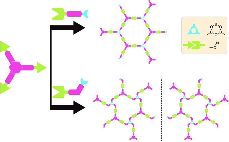
 The orthogonality between the Schiff base reaction and the boronic acid dehydration reaction is explored during the on-surface synthesis process.
Abstract
The orthogonality between the Schiff base reaction and the boronic acid dehydration reaction is explored during the on-surface synthesis process. By activating the above two reactions in one-step and employing asymmetrical substituted monomers and the 3-fold symmetric monomer 1,3,5-tris(4-aminophenyl)benzene (TAPB), highly ordered imine–boroxine hybrid single-layered covalent organic frameworks (sCOFs) have been successfully constructed on HOPG by a gas–solid interface reaction method and characterized by scanning tunnelling microscopy (STM). In particular, the reaction between the meta-substituted monomer and TAPB generates sCOFB with a windmill structure, which is the first sCOF with surface chirality so far reported. The demonstration of the one-step synthesis of multiple linkages to form sCOFs can further enlarge the sCOF family and expand the design routes for functional 2D organic nanomaterials.
Introduction
The discovery of interesting properties associated with two dimensional (2D) materials,1,2 such as graphene, transition metal chalcogenides, hexagonal boron nitride and silicene, has stimulated the booming development of the synthesis and application of 2D nanostructures and materials.3,4 Single-layered covalent organic frameworks (sCOFs),5–10 featuring graphene-like but adjustable topological structures and tunable organic functional moieties, have attracted enormous interest as a new member of the 2D materials family and have been predicted to have great application potential in optoelectronic devices, molecular electronics and sensors.11 On-surface synthesis has been a promising method to fabricate sCOFs.12 So far, different linkages have been exploited to achieve the synthesis of diverse sCOFs, such as boroxine,5–7 boronate ester,5 the imine bond,8–10,13 the C–C bond,14–17 the acetylene linkages18–20 and so on. Notably, however, most of the sCOFs reported so far usually have single linkages. To further broaden the family of sCOF structures, it is desirable to develop sophisticated and multi-component molecular covalent nanostructures using multiple linkages.
When two chemical reactions are mutually compatible and occur without crosstalking, they can be defined as orthogonal reactions. Orthogonal reactions have served as a powerful toolbox in chemistry, such as in the synthesis of dendritic macromolecules,21 the fabrication of functional nanocapsules,22 the preparation of core–shell nanoparticles23 and the construction of covalent organic frameworks (COFs).24,25 Previously, a few reports have demonstrated a hierarchical construction strategy to achieve sCOFs with improved ordered structures by sequential activation of two orthogonal chemical reactions. For example, Grill et al. demonstrated that by sequentially activating the I- and Br- based Ullmann reaction based on the bond dissociation energies, sCOFs show larger ordered domain sizes.26 Similarly, phenylene–boroxine sCOFs have been obtained in two steps by thermally activating the condensation reaction of boronic acid and the subsequent Ullmann reaction.17,19 However, this strategy is so far limited to 2D polymerization of a single component equipped two different reaction motifs. To further expand the diversity of the sCOF structure, it is desirable to develop a methodology for bi- or multi- component reactions. Generally, the formation of highly ordered sCOFs requires precise control of the conformation of each precursor.27 Furthermore, to achieve the ideal 2D polymerization of two components, linkages should be formed in the correct order during the reaction process. Therefore, it is rational to deduce that the simultaneous activation of two or more orthogonal reactions in one stage is a more practical way to achieve highly ordered sCOFs with multiple linkages.
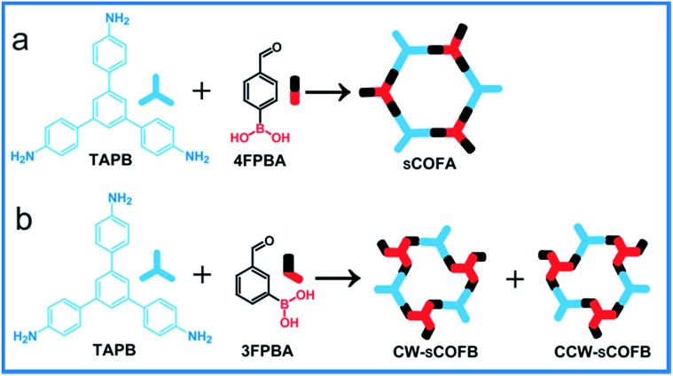
Herein, we report the simultaneous fabrication of imine–boroxine hybrid sCOFs by orthogonal reactions of the Schiff base reaction and the boronic acid dehydration reaction. Reversible reactions are characteristic of dynamic covalent bonds,28 which can form and reform during the reaction process, providing error-checking and self-healing opportunities. The Schiff base reaction and the boronic acid dehydration reaction are typical reversible reactions and have been widely applied in the synthesis of macrocycles, polymers and COFs.29–31 Previously, the orthogonal character of these two reactions has been demonstrated in solution phase chemistry,32,33 and is an important prerequisite to achieve hybrid sCOFs. Scheme 1 shows the reticular structure design of hybrid sCOFs. The bifunctional precursor 4-formylphenylboronoic acid (4FPBA) was asymmetrically installed with a boronic acid group for the boroxine linkage, and an aldehyde group for the Schiff base reaction can react with 3-fold symmetry monomers 1,3,5-tris(4-aminophenyl)benzene (TAPB) to attain 2D sCOFs. By adapting the gas–solid interface reaction method we recently developed for the synthesis of imine-based sCOFs,8 we successfully obtain a highly ordered imine–boroxine hybrid sCOFA featuring two different vertices units. Furthermore, by changing the position of the reaction groups on the phenyl ring (Scheme 1b), we successfully fabricate the windmill structure containing sCOFB, which is the first covalent network featuring surface chirality, to the best of our knowledge. The demonstration of the one-step construction of multiple linkages to form sCOFs can further broaden the sCOF family and enrich the design toolbox for functional 2D organic nanomaterials.
Scheme 1. Schematic diagram of the fabrication of sCOFs via orthogonal reactions. (a) The formation of sCOFA from molecules TAPB and 4FPBA. (b) The formation of CW-sCOFB and CCW-sCOFB from molecules TAPB and 3FPBA.
Results and discussion
Firstly, we utilize TAPB and 4FPBA as building blocks to explore suitable synthetic conditions for hybrid sCOFs. We adapt the gas–solid interface reaction methods that were recently developed to synthesize highly ordered imine-based sCOFs8 to obtain hybrid sCOFs. In brief, the molecule TAPB was deposited on freshly cleaved highly oriented pyrolytic graphite (HOPG) by drop-casting. Then the HOPG loaded with molecule TAPB was placed into a reactor with 4FPBA powder as the other precursor for sCOF construction and CuSO4·5H2O powder as a chemical equilibrium control agent.6 The reactor was closed in an autoclave and heated at 120 °C for 3 h. After the reactor was cooled down to room temperature, the HOPG was taken out and characterized by STM.
Fig. 1a presents a typical large-scale STM image of sCOFA resulting from the condensation of molecule TAPB and 4FPBA at 120 °C. The HOPG surface is almost fully covered with honeycomb networks. The typical domain size is more than 80 × 80 nm2. The networks in the neighboring domains show the same orientation, indicating that the growth of the network is guided by the crystalline orientation of the substrate.8,34 The comparison between the growth orientation of sCOFA and the atom image of the underlying HOPG indicates that the network orientates along with the lattice of the substrate (ESI Fig. S1†). Six scattering spots are observed through 2D fast Fourier transformation (FFT) (inset in Fig. 1a) and the intensities between them cannot be distinguished clearly. Although sCOFA has 3-fold symmetry, the boroxine ring and the benzene ring at the vertices of the networks are barely discernable in the STM image (vide infra), and thus a hexagonal network is observed. The structural details of sCOFA are revealed by the high resolution STM image in Fig. 1b. A 2D continuous sCOF adlayer is observed, although some of the hexagons are distorted. Furthermore, defects due to the discontinuous network can also be observed, as indicated by the pink arrows in Fig. 1b. These distorted hexagons may result from the trans-/cis- configurations of the imine linkages.27,35 A schematic structural model for the distorted hexagons with mixed trans-/cis- configurations of the imine bonds is shown in Fig. S2.† The formation of a 2D continuous network, regardless of the trans-/cis- configuration of the imine bonds, can be ascribed to the substrate orientation effect for on-surface synthesis. According to the STM image, the lattice parameters of sCOFA are measured to be a = b = 2.7 ± 0.1 nm and γ = 60 ± 1°, which are consistent with the structural modelling. In addition, due to the similar size of the boroxine ring and the benzene ring, the trimer condensed by 4FPBA has a size close to the molecule 1,3,5-tris(4-formylphenyl)benzene (TFPB).36 A comparison between the trimer condensed by 4FPBA and molecule TFPB is shown in Fig. S3.† The similar lattice parameters between sCOFA and the sCOF fabricated by TAPB and TFPB further demonstrates that sCOFA is connected by hybrid covalent linkages. The vertices of the hexagons are made up of alternate aromatic rings and boroxine rings, but they have similar contrast and size, as shown by the white circles in Fig. 1b, and cannot be discerned by STM. A structure model for sCOFA is shown in Fig. 1c. The blue modules represent the aromatic rings of TAPB, while the red modules are the boroxine rings condensed by the boronic acid moiety of 4FPBA.
Fig. 1. STM images and a structural model for sCOFA. (a) Large-scale STM image (100 × 100 nm2) of sCOFA with the inset depicting the corresponding FFT spectrum of the STM image. (b) High resolution STM image (20 × 20 nm2) of sCOFA. The pink arrows direct to a location where a precursor is missing. The white rings display the vertices of sCOFA. (c) A structural model for hybrid sCOFA. The blue modules represent the aromatic rings of the TAPB, while the red modules are the boroxine rings condensed by 4FPBA. Imaging conditions: (a) V bias = 700 mV, I t = 500 pA; (b) V bias = 600 mV, I t = 650 pA.
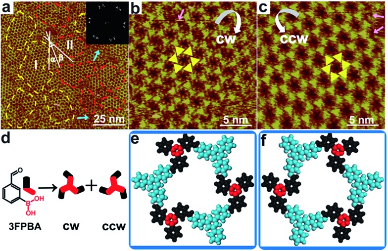
Next, we designed hybrid sCOFB by choosing another bifunctional building block 3FPBA. 3FPBA is the isomer of 4FPBA, with a boronic acid group and an aldehyde group at the meta-position of a phenyl ring. We expected that 3FPBA could form windmill trimers on the surface and therefore sCOFs with surface chirality could be created. The reaction results are displayed in Fig. 2. Fig. 2a displays a representative 100 × 100 nm2 STM image of sCOFB. Ordered honeycomb domains with two orientations are observed on the HOPG. The yellow dotted line areas are phase I and the red dotted line areas represent phase II. The twelve scattering spots displayed in the inset 2D FFT image of Fig. 2a further demonstrate the two phases of sCOFB. The epitaxial orientation of the sCOFB domains to the underlying substrate was obtained by comparing the STM image of the adlayer and the atomic image of HOPG of the same area obtained at the proper tunnelling condition (see ESI Fig. S4† for details). The angle between the lattice orientation of phase I or phase II relative to the underlying HOPG substrate (represented by α or β in Fig. 2a) is measured to be 20 ± 2° and –20 ± 2°, respectively. Other than the ordered hexagonal areas, the disordered structures can also be observed at the boundary of the ordered domains, as indicated by the blue arrows in Fig. 2a.
Fig. 2. STM images and structural models for sCOFB. (a) Large-scale STM image (100 × 100 nm2) of sCOFB with the corresponding FFT of the STM image inserted. The yellow dotted line areas are phase I and the red dotted line areas represent phase II. The angle between phase I and the underlying HOPG substrate is represented by α and the angle between phase II and the underlying HOPG substrate is shown as β. The blue arrows show the disordered structures between the ordered domains. (b, c) High resolution STM images (20 × 20 nm2) of CW-sCOFB and CCW-sCOFB, respectively. The yellow symbols represent a chiral hexamer. The white arrows reveal the rotational direction of the chiral hexamer. The pink arrows direct to a location where a precursor is missing. (d) Possible trimers polymerized by 3FPBA. (e, f) Structural models for CW-sCOFB and CCW-sCOFB. The blue components are aromatic rings of TAPB and the red components represent the boroxine rings condensed by 3FPBA. Imaging conditions: (a) V bias = 700 mV, I t = 500 pA; (b, c) V bias = 550 mV, I t = 600 pA.
The structural details of phase I and phase II are revealed by the high-resolution STM images in Fig. 2b and c, respectively. The vertices of the hexagonal networks are resolved as triangles, as depicted by the yellow triangles in Fig. 2b and c. The lengths of the triangular units are about 0.9 ± 0.1 nm, in accordance with the size of the molecule TAPB and the trimers condensed by molecule 3FPBA. By analysing the rotation manner of the triangles to form a hexamer, we find that the ordered hexagonal domains all have surface chirality. CW-sCOFB is used as the notation when the hexamer spins clockwise as illustrated by the white arrow in Fig. 2b. When the hexamer rotates anticlockwise as displayed in Fig. 2c, CCW-sCOFB is obtained. According to the molecular structure, we can infer that different kinds of trimers, the CW-trimer and the CCW-trimer as described in Fig. 2d, can be formed by the boroxine ring condensation reaction. The reaction between TAPB and the CCW-trimer leads to the formation of CW-sCOFB while the reaction between TAPB and the CW-trimer results in the CCW-sCOFB. The confirmation of the surface chirality from high resolution STM imaging is consistent with the epitaxial orientation results shown in Fig. 2a. The comparison of the growth orientation between sCOFA and sCOFB (Fig. S5†) indicates that the surface chirality of sCOFB can be attributed to the substrate-molecule interaction of TAPB. Although similar surface chirality induction has been widely observed in non-covalent interaction driven surface assembly systems,37–39 this is the first time, to the best of our knowledge, that a covalent network with surface chirality has been obtained. The unit cell parameters of the ordered hexagonal network sCOFB are determined to be a = b = 2.5 ± 0.1 nm and γ = 60 ± 1°, which is in agreement with the structural modelling for a covalent bond linked hybrid sCOF. The evidence for imine bond formation in SCOFB is further supported by X-ray photoelectron spectroscopy (XPS, Fig. S6†). The N 1s spectrum of the TAPB molecule on HOPG shows a peak at 399.8 eV (Fig. S6b†) and is attributed to the N in the amine group.8,40–44 Upon reaction to form sCOFB, the N 1s spectrum can be deconvoluted into two bands at 399.8 eV and 398.5 eV (Fig. S6d†), and a new band at 398.5 eV is the characteristic peak for the N in the imine bond.8,40–44 According to the STM images and the analysis above, structure models for CW-sCOFB and CCW-sCOFB are proposed in Fig. 2e and f. The boroxine rings condensed by trimerization are represented by the red components and the aromatic rings are disclosed by the blue modules.
Previously, we have demonstrated that the gas–solid interface reaction method is a general method to attain highly ordered sCOFs with imine linkages.8 The advantage of the gas–solid interface method is that the nucleation process is suppressed and the growth process is promoted. We also perform a control experiment by depositing the mixture solution of precursors TAPB and 4FPBA/3FPBA on HOPG together while keeping the other experimental conditions the same. Only disordered structures with incomplete reaction intermediates and oligomers can be obtained as displayed in Fig. S7.† In addition, the water releasing agent CuSO4·5H2O6 plays an important role in the growth process of sCOFs. The presence of CuSO4·5H2O in the closed reaction system can help to improve the reversibility of the dynamic covalent bonds, such as the boroxine ring and the imine bond. Without the thermodynamic regulation agent, the defects produced in the reaction process cannot be repaired efficiently and disordered structures cover the substrate, as displayed in Fig. S8.†
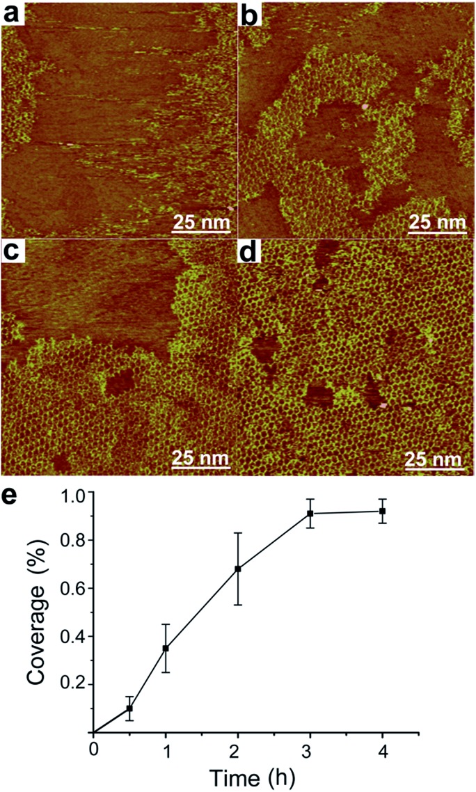
We further investigate the time evolution of hybrid sCOF growth. Fig. 3a–d present typical STM images of sCOFA obtained after different reaction times of 0.5 h, 1 h, 2 h and 3 h, respectively. The ordered structures start to form even at short reaction time/low coverage. The increase in reaction time results in the growth of an ordered domain and finally a high coverage sCOF is obtained at reaction times of 3–4 h. A plot of the coverage of sCOFA against the reaction time is shown in Fig. 3e. Such an observation indicates that the gas–solid interface reaction method is effective to suppress the nucleation step and promote the growth of highly ordered sCOF. Similar time evolution behavior is observed for sCOF of pure imine linkage,8 indicating that the formation of two linkages proceeds on a similar time scale and has no effect on each other.
Fig. 3. Effect of reaction time on the growth of sCOFA. STM images (a, b, c and d; 100 × 100 nm2) of sCOFA achieved after heating at the gas–solid interface at 120 °C for different reaction times of (a) 0.5 h, (b) 1 h, (c) 2 h and (d) 3 h. (e) Dependence of the coverage of sCOFA on the reaction time. Imaging conditions: (a) V bias = 700 mV, I t = 500 pA; (b) V bias = 700 mV, I t = 650 pA; (c) V bias = 700 mV, I t = 600 pA; (d) V bias = 700 mV, I t = 500 pA.
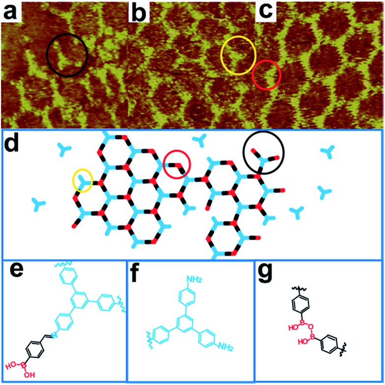
We propose that the imine bond and boroxine ring are formed on a similar time scale during the growth of hybrid sCOFs. Firstly, we do not capture the single linkage linked oligomers, which are single imine bond linked oligomers (formed by molecule TAPB and 4FPBA in a ratio of 1 : 3) and single boroxine ring linked oligomers (trimers condensed by molecule 4FPBA). Secondly, the nucleation and growth process of imine and boroxine hybrid sCOFs is similar to that of pure imine linked networks.8 Thus, the formation of imine bonds and boroxine rings proceeds at a similar rate and does not crosstalk during the reaction. Moreover, the structural details at the boundaries of sCOFA during the growth process indicate that two reactions can occur together. Fig. 4a–c show high resolution STM images of sCOFA formed in a short reaction time of 1 h. Several structural defects at the boundaries are identified, such as a long trefoil structure, a short trefoil structure and a zig–zag structure, as described by the structure model in Fig. 4d. The long trefoil structure, outlined by the black ring in Fig. 4a, can be attributed to the reaction between molecule TAPB and molecule 4FPBA with unreacted boric acid groups. The chemical structure of the long trefoil is shown in Fig. 4e. The short trefoil structure displayed by the yellow ring in Fig. 4b is attributed to the not fully reacted molecule TAPB. The chemical structure of the short trefoil is shown in Fig. 4f. The zig–zag structure, shown by the red ring in Fig. 4c, can be ascribed to the unclosed boroxine from two 4FPBA molecules. The chemical structure of the zig–zag structure is shown in Fig. 4g. These phenomena demonstrate that the Schiff base reaction and the boronic acid dehydration reaction are activated on the surface and the imine–boroxine hybrid sCOFs form at one stage.
Fig. 4. STM images (a, b and c; 10 × 10 nm2) of the boundaries of sCOFA during the reaction process. (a) The long trefoil structure, outlined by the black ring. (b) The short trefoil structure highlighted by the yellow ring. (c) The zig–zag structure shown by the red ring. (d) Structural models for the boundaries of sCOFA during the reaction process. (e) Chemical structure for the long trefoil structure. (f) Chemical structure for the short trefoil structure. (g) Chemical structure for the zig–zag structure. Imaging conditions: V bias = 650 mV, I t = 660 pA.
Furthermore, the stability of the hybrid sCOFs is explored since it is an important issue for their potential applications. The ordered sCOFA can still be observed (Fig. S9a†) after annealing at 180 °C for 1 h under ambient conditions, indicating that the hybrid sCOF is of good stability. Moreover, after being stored under ambient conditions for 20 days, highly ordered sCOFB can still be observed (Fig. S10†), which demonstrates that the hybrid sCOF is more stable than single boroxine ring linked sCOFs.6 On the other hand, when sCOFA is in contact with an acidic (pH = 3) or basic solution (pH = 11), the areas of the ordered networks decrease and chaotic structures appear (Fig. S9b and c†), which may be ascribed to the labile character of both of the linkages to pH.
Conclusions
In summary, we successfully introduce bifunctional building blocks into on-surface synthesis and fabricate hybrid sCOFs linked by boroxine rings and imine bonds. These hybrid sCOFs feature structural complexity from multiple linkages and different vertex molecular modules. In particular, sCOFB contains covalent-bonded windmill structures and has surface chirality, which is the first reported chiral sCOF, to the best of our knowledge. We demonstrate that the Schiff base reaction and boronic acid dehydration have orthogonality during on-surface synthesis and they can take place concurrently, which is important for the formation of highly ordered hybrid sCOFs. The one-step orthogonal reaction strategy enlarges the variety of building blocks which can be utilized in on-surface synthesis and paves the way to fabricate multi-component molecular nanostructures with novel structures and functions.
Acknowledgments
This work was supported by National Natural Science Foundation of China (21433011, 91527303, 21233010, 21373236, 21127901), and the Strategic Priority Research Program of the Chinese Academy of Sciences (Grant No. XDB12020100).
Footnotes
References
- Butler S. Z., Hollen S. M., Cao L.-Y., Cui Y., Gupta J. A., Gutiérrez H. R., Heinz T. F., Hong S. S., Huang J.-X., Ismach A. F., Johnston-Halperin E., Kuno M., Plashnitsa V. V., Robinson R. D., Ruoff R. S., Salahuddin S., Shan J., Shi L., Spencer M. G., Terrones M., Windl W., Goldberger J. E. ACS Nano. 2013;7:2898–2926. doi: 10.1021/nn400280c. [DOI] [PubMed] [Google Scholar]
- Colson J. W., Dichtel W. R. Nat. Chem. 2013;5:453–465. doi: 10.1038/nchem.1628. [DOI] [PubMed] [Google Scholar]
- Wang Q.-H., Kalantar-Zadeh K., Kis A., Coleman J. N., Strano M. S. Nat. Nanotechnol. 2012;7:699–712. doi: 10.1038/nnano.2012.193. [DOI] [PubMed] [Google Scholar]
- Ando T., Fowler A. B., Stern F. Rev. Mod. Phys. 1982;54:437–672. [Google Scholar]
- Zwaneveld N. A. A., Pawlak R., Abel M., Catalin D., Gigmes D., Bertin D., Porte L. J. Am. Chem. Soc. 2008;130:6678–6679. doi: 10.1021/ja800906f. [DOI] [PubMed] [Google Scholar]
- Guan C. Z., Wang D., Wan L. J. Chem. Commun. 2012;48:2943–2945. doi: 10.1039/c2cc16892h. [DOI] [PubMed] [Google Scholar]
- Dienstmaier J. F., Medina D. D., Dogru M., Knochel P., Bein T., Heckl W. M., Lackinger M. ACS Nano. 2012;6:7234–7242. doi: 10.1021/nn302363d. [DOI] [PubMed] [Google Scholar]
- Liu X.-H., Guan C.-Z., Ding S.-Y., Wang W., Yan H.-J., Wang D., Wan L.-J. J. Am. Chem. Soc. 2013;135:10470–10474. doi: 10.1021/ja403464h. [DOI] [PubMed] [Google Scholar]
- Xu L.-R., Zhou X., Yu Y.-X., Tian W.-Q., Ma J., Lei S.-B. ACS Nano. 2013;7:8066–8073. doi: 10.1021/nn403328h. [DOI] [PubMed] [Google Scholar]
- Yue J.-Y., Liu X.-H., Sun B., Wang D. Chem. Commun. 2015;51:14318–14321. doi: 10.1039/c5cc05689f. [DOI] [PubMed] [Google Scholar]
- Perepichka D. F., Rosei F. Science. 2009;323:216–217. doi: 10.1126/science.1165429. [DOI] [PubMed] [Google Scholar]
- El Garah M., MacLeod J. M., Rosei F. Surf. Sci. 2013;613:6–14. [Google Scholar]
- Liu X.-H., Mo Y.-P., Yue J.-Y., Zheng Q.-N., Yan H.-J., Wang D., Wan L.-J. Small. 2014;10:4934–4939. doi: 10.1002/smll.201400899. [DOI] [PubMed] [Google Scholar]
- Shi K.-J., Yuan D.-W., Wang C.-X., Shu C.-H., Li D.-Y., Shi Z.-L., Wu X.-Y., Liu P.-N. Org. Lett. 2016;18:1282–1285. doi: 10.1021/acs.orglett.6b00172. [DOI] [PubMed] [Google Scholar]
- Fan Q.-T., Wang C.-C., Han Y., Zhu J.-F., Hieringer W., Kuttner J., Hilt G., Gottfried J. M. Angew. Chem., Int. Ed. 2013;52:4668–4672. doi: 10.1002/anie.201300610. [DOI] [PubMed] [Google Scholar]
- Schlogl S., Sirtl T., Eichhorn J., Heckl W. M., Lackinger M. Chem. Commun. 2011;47:12355–12357. doi: 10.1039/c1cc13896k. [DOI] [PubMed] [Google Scholar]
- Faury T., Clair S., Abel M., Dumur F., Gigmes D., Porte L. J. Phys. Chem. C. 2012;116:4819–4823. [Google Scholar]
- Eichhorn J., Heckl W. M., Lackinger M. Chem. Commun. 2013;49:2900–2902. doi: 10.1039/c3cc40444g. [DOI] [PubMed] [Google Scholar]
- Schlogl S., Sirtl T., Eichhorn J., Heckl W. M., Lackinger M. Chem. Commun. 2011;47:12355–12357. doi: 10.1039/c1cc13896k. [DOI] [PubMed] [Google Scholar]
- Zhang Y.-Q., Kepcija N., Kleinschrodt M., Diller K., Fischer S., Papageorgiou A. C., Allegretti F., Bjork J., Klyatskaya S., Klappenberger F., Ruben M., Barth J. V. Nat. Commun. 2012;3:1286–1293. doi: 10.1038/ncomms2291. [DOI] [PubMed] [Google Scholar]
- Killops K. L., Campos L. M., Hawker C. J. J. Am. Chem. Soc. 2008;130:5062–5064. doi: 10.1021/ja8006325. [DOI] [PubMed] [Google Scholar]
- Fickert J., Makowski M., Kappl M., Landfester K., Crespy D. Macromolecules. 2012;45:6324–6332. [Google Scholar]
- Joralemon M. J., O'Reilly R. K., Hawker C. J., Wooley K. L. J. Am. Chem. Soc. 2005;127:16892–16899. doi: 10.1021/ja053919x. [DOI] [PubMed] [Google Scholar]
- Zeng Y.-F., Zou R.-Y., Luo Z., Zhang H.-C., Yao X., Ma X., Zou R.-Q., Zhao Y.-L. J. Am. Chem. Soc. 2015;137:1020–1023. doi: 10.1021/ja510926w. [DOI] [PubMed] [Google Scholar]
- Chen X., Addicoat M., Jin E.-Q., Xu H., Hayashi T., Xu F., Huang N., Irle S., Jiang D.-L. Sci. Rep. 2015;5:14650–14668. doi: 10.1038/srep14650. [DOI] [PMC free article] [PubMed] [Google Scholar]
- Lafferentz L., Eberhardt V., Dri C., Africh C., Comelli G., Esch F., Hecht S., Grill L. Nat. Chem. 2012;4:215–220. doi: 10.1038/nchem.1242. [DOI] [PubMed] [Google Scholar]
- Schmitz C. H., Ikonomov J., Sokolowski M. J. Phys. Chem. C. 2011;115:7270–7278. [Google Scholar]
- Rowan S. J., Cantrill S. J., Cousins G. R. L., Sanders J. K. M., Stoddart J. F. Angew. Chem., Int. Ed. 2002;41:898–952. doi: 10.1002/1521-3773(20020315)41:6<898::aid-anie898>3.0.co;2-e. [DOI] [PubMed] [Google Scholar]
- Iyoda M., Yamakawa J., Rahman M. J. Angew. Chem., Int. Ed. 2011;50:10522–10553. doi: 10.1002/anie.201006198. [DOI] [PubMed] [Google Scholar]
- Mastalerz M. Angew. Chem., Int. Ed. 2010;49:5042–5053. doi: 10.1002/anie.201000443. [DOI] [PubMed] [Google Scholar]
- Zhang W., Moore J. S. Angew. Chem., Int. Ed. 2006;45:4416–4439. doi: 10.1002/anie.200503988. [DOI] [PubMed] [Google Scholar]
- Hagihara S., Tanaka H., Matile S. J. Am. Chem. Soc. 2008;130:5656–5657. doi: 10.1021/ja801094p. [DOI] [PubMed] [Google Scholar]
- Cal P. M. S. D., Vicente J. B., Pires E., Coelho A. V., Veiros L. S. F., Cordeiro C., Gois P. M. P. J. Am. Chem. Soc. 2012;134:10299–10305. doi: 10.1021/ja303436y. [DOI] [PubMed] [Google Scholar]
- Dong W.-L., Wang L., Ding H.-M., Zhao L., Wang D., Wang C., Wan L.-J. Langmuir. 2015;31:11755–11759. doi: 10.1021/acs.langmuir.5b02412. [DOI] [PubMed] [Google Scholar]
- Sun X.-L., Fan L.-X., Zhou X., Tian W.-Q., Guo Z.-X., Li Z.-B., Li X.-K., Lei S.-B. Chem. Commun. 2015;51:5864–5867. doi: 10.1039/c5cc00659g. [DOI] [PubMed] [Google Scholar]
- Liu X.-H., Guan C.-Z., Zheng Q.-N., Wang D., Wan L.-J. J. Chem. Phys. 2015;142:101905–101910. doi: 10.1063/1.4906271. [DOI] [PubMed] [Google Scholar]
- Chen Q., Chen T., Wang D., Liu H.-B., Li Y.-L., Wan L.-J. Proc. Natl. Acad. Sci. U. S. A. 2010;107:2769–2774. doi: 10.1073/pnas.1000120107. [DOI] [PMC free article] [PubMed] [Google Scholar]
- Chen T., Yang W.-H., Wang D., Wan L.-J. Nat. Commun. 2013;4:1389–1396. doi: 10.1038/ncomms2403. [DOI] [PMC free article] [PubMed] [Google Scholar]
- De Feyter S., De Schryver F. C. Chem. Soc. Rev. 2003;32:139–150. doi: 10.1039/b206566p. [DOI] [PubMed] [Google Scholar]
- Golczak S., Kanciurzewska A., Fahlman M., Langer K., Langer J. J. Solid State Ionics. 2008;179:2234–2239. [Google Scholar]
- Graf N., Yegen E., Gross T., Lippitz A., Weigel W., Krakert S., Terfort A., Unger W. E. S. Surf. Sci. 2009;603:2849–2860. [Google Scholar]
- Di Giovannantonio M., Kosmala T., Bonanni B., Serrano G., Zema N., Turchini S., Catone D., Wandelt K., Pasini D., Contini G., Goletti C. J. Phys. Chem. C. 2015;119:19228–19235. [Google Scholar]
- Hu Y., Goodeal N., Chen Y., Ganose A. M., Palgrave R. G., Bronstein H., Blunt M. O. Chem. Commun. 2016;52:9941–9944. doi: 10.1039/c6cc03895f. [DOI] [PubMed] [Google Scholar]
- Tang Z.-Y., Liu S.-Q., Wang Z.-X., Dong S.-J., Wang E.-K. Electrochem. Commun. 2000;2:32–35. [Google Scholar]
Associated Data
This section collects any data citations, data availability statements, or supplementary materials included in this article.


