Abstract
A modified National Operating Committee on Standards for Athletic Equipment (NOCSAE) test method for American football helmet drop impact test standards is presented that would provide better assessment of a helmet's on-field impact performance by including a faceguard on the helmet. In this study, a merger of faceguard and helmet test standards is proposed. The need for a more robust systematic approach to football helmet testing procedures is emphasized by comparing representative results of the Head Injury Criterion (HIC), Severity Index (SI), and peak acceleration values for different helmets at different helmet locations under modified NOCSAE standard drop tower tests. Essentially, these comparative drop test results revealed that the faceguard adds a stiffening kinematic constraint to the shell that lessens total energy absorption. The current NOCSAE standard test methods can be improved to represent on-field helmet hits by attaching the faceguards to helmets and by including two new helmet impact locations (Front Top and Front Top Boss). The reported football helmet test method gives a more accurate representation of a helmet's performance and its ability to mitigate on-field impacts while promoting safer football helmets.
Keywords: Bioengineering, Issue 120, Concussion, Traumatic Brain Injury, Head Injury Criterion, Gadd Severity Index, National Operating Committee on Standards for Athletic Equipment, American football helmet testing
Introduction
Motivation The main goal of this modified drop tower test method is to more closely represent on-field impacts of the American football helmet system and promote enhanced safety standards. The entailed test method can provide knowledge of helmets systematic response needed to effectively develop enhanced headgear for concussion prevention. The occurrence of concussions has persistently plagued contact sports, such as American Football. In the United States alone, sports-related concussions have been estimated to occur 1.6 to 3.8 million times every year.1 A football player can have more than 1,500 head impacts each season.2,3 While the magnitude of most impacts may be sub-concussive, the accumulation of these impacts may lead to long-term brain damage due to an impact induced neurodegenerative ailment known as chronic traumatic encephalopathy (CTE).4 CTE is linked to a buildup of tau protein in the brain, leading to memory loss, behavior and personality change, Parkinson's syndrome, and speech and gait abnormalities that has sometimes led to suicide.5 Football helmets have made some technological advancements in the past 15 years, but even today's most advanced helmets do not completely mitigate all of the incident forces on the helmet and hence, athletes still incur concussions. A study conducted by Bartsch et al.6 showed that in many cases the head impact doses and head injury risks while wearing vintage leatherhead helmets were comparable to those wearing the widely used 21st century helmets, illustrating the need for improvement in the design and testing standards of football helmets. In particular, the NOCSAE certification7 does not require the faceguard to be included in the drop tests for the helmet. The added stiffness from the faceguard connected to the helmet would dramatically change the overall mechanical response. The present study entails a method to provide more robust helmet safety standards that would serve as a driving force to promote safer helmet designs.
Background Head Injury Metrics The exact biological mechanisms related to concussions remain unidentified. While much work has been done in attempting to quantify head injury tolerances by various injury metrics, disagreement has arisen in the biomedical community regarding these criteria. These injury mechanisms are supposed to relate to several entities: linear acceleration, rotational acceleration, impact duration, and impulse.8,9,10,11 Several Injury criteria have been used to define a concussion as a measure of linear acceleration. The Wayne State Tolerance Curve (WSTC)12,13,14 was developed to predict skull fracture for automotive crashes during a frontal impact by defining a threshold curve boundary for linear acceleration versus impact duration. WSTC has served as the bases for other injury criteria such as the Severity Index (SI)11and the Head Injury Criterion (HIC),15 which are the two most commonly used criteria. The SI and HIC both measure impact severity based on weighted integrals of the linear acceleration-time profiles. While these criteria define thresholds for linear acceleration, other criteria have been proposed to account for rotational acceleration, such as the Head Impact Power index.8,10,16 Today's helmet testing standards often use an injury criterion based upon the Wayne State Tolerance Curve (namely HIC or SI) or the peak acceleration criterion or in some cases both. While some modifications are needed to add angular acceleration to the standard performance criteria, the linear acceleration-based criteria remain dominant.
In this study, the metrics used to assess the relative safety that each helmet provided were the peak resultant accelerations, SI, and HIC values. Of these metrics only the SI is used for evaluation in the current National Operating Committee on Standards for Athletic Equipment (NOCSAE) football helmet standards. The SI is based on the following equation,
 (1)
(1)
where A is the translational acceleration of the Center of Gravity (CG) of the head, and t is the acceleration duration.11,17SI was calculated according to NOCSAE standards18, where the calculation is limited by a 4 G threshold along the resultant acceleration curve. The HIC values were calculated by the following equation,
 (2)
(2)
where a is the translational acceleration of the CG of the head, and t1 and t2 are the initial and final times, respectively, of the interval at which HIC attains a maximum value. All HIC values calculated in this study were HIC36, where the duration of the time interval is limited to 36 ms.
NOCSAE Football Helmet Test Standards NOCSAE Overview In 1969 NOCSAE was formed to develop performance standards for American football helmets/faceguards and other sporting equipment with a goal of reducing sports-related injuries.17 The NOCSAE football helmet standards were developed by Dr. Voigt Hodgson9 of Wayne State University to reduce head injuries by establishing requirements for impact attenuation and structural integrity for football helmets/faceguards. These football helmet standards include a certification test and annual recertification procedures for helmets. In 2015, NOCSAE implemented a quality assurance program requiring the use of a specific American National Standards Institute (ANSI) accredited body for helmet certification.
NOCSAE Test Method The NOCSAE Football Helmet Standard does not include the testing of helmets with faceguards as it calls for their removal before helmet drops are conducted. The NOCSAE helmet testing standards17 utilize a twin-wire drop impactor that relies on gravity to accelerate the headform and helmet combination to the required impact speeds. The NOCSAE headform is instrumented with triaxial accelerometers at the center of gravity. The headform and helmet combination is then dropped at specific speeds onto a steel anvil covered with a 12.7 mm thick hard rubber Modular Elastomer Programmer (MEP) pad. Upon impact, the instantaneous acceleration is recorded and SI values are calculated. These SI values are compared against a pass/fail criterion over a variety of required impact locations and velocities and two temperatures, including ambient and high temperature impacts. If the resulting SI value for any impact breaches the threshold, then the helmet will not pass the test.
A separate standard test method is used for football faceguard certification. The NOCSAE football faceguard standard includes structural integrity analysis as well as assessing the impact attenuation performance of the faceguard, chinstrap, and their attachment systems. Each impact measurement must be below 1,200 SI to pass the test, with no facial contact and no mechanical failure of any component, as defined by the NOCSAE Standard.19
There is a proposed additional NOCSAE test (Linear Impactor (LI))20 that includes the helmet with the faceguard, but it is not appropriate for football helmet certification because it cannot admit a crown impact. The LI uses a pneumatic ram to impact a helmet positioned on a NOCSAE headform equipped with a hybrid III dummy neck mounted on a linear bearing table in order to induce angular acceleration. For this reason the LI test is an additional test to the current twin-wire NOCSAE drop test procedure and not a replacement.20,21 Instead of the LI tests, we propose to simply add two more scenarios to the current twin-wire drop test procedure.
The NOCSAE standard test method for certification of football helmets currently includes six prescribed impact locations and one random impact location. The prescribed impact locations include the following: Front (F), Front Boss (FB), Side (S), Rear (R), Rear Boss (RB), and Top (T). The random impact location test may select a region from any point within the defined acceptable impact area of the helmet. The impact locations for our modified NOCSAE drop tower tests include replacing the previously defined Front and Front Boss impact locations with what was named as the Front Top (FT) and Front Top Boss (FTB) impact locations. Our Front Top and Front Top Boss impact locations are identical to the Front and Right Front Boss impact locations of the NOCSAE standard for Lacrosse Helmets, which also include the faceguard for drop tests.22 The helmet shell impact locations, including the replaced Front and Front Boss locations, are depicted in Figure 1.Additionally, the modified helmet test method of our present study includes two faceguard impact locations that were named the FG Front and FG Bottom. The two faceguard impacts locations are identical to the required impact locations for the current NOCSAE faceguard certification procedures. The eight impact locations for the modified NOCSAE impact tests of the present study are shown in Figure 2.
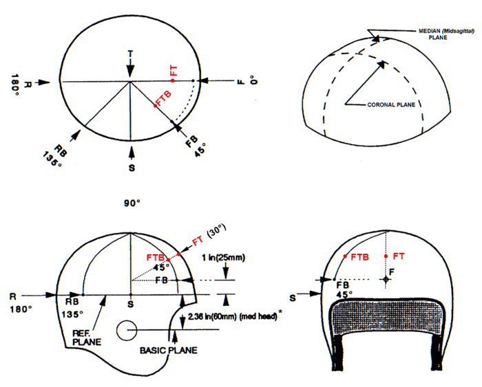 Figure 1: Approximate impact locations for football helmets. The six currently required NOCSAE drop test helmet impact locations, Front (F), Front Boss (FB), Side (S), Top (T), Rear (R), and Rear Boss (RB), and the two proposed impact locations, Front Top (FT), and Front Top Boss (FTB). Note: the NOCSAE standard test method for protective headgear does not include Front Top and Front Top Boss impact locations (indicated in red text) and for this study they replace the Front and Front Boss impact locations. (Image modified from NOCSAE DOC. 001-13m15b) Please click here to view a larger version of this figure.
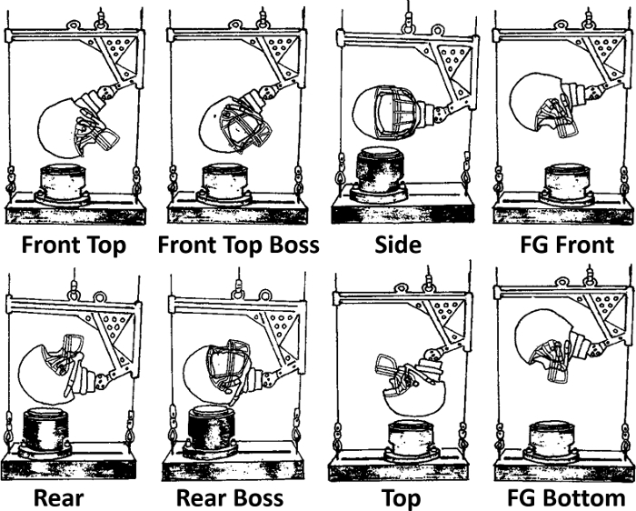 Figure 2: Modified NOCSAE drop test setup showing eight impact locations. Front Top, Front Top Boss, Side, Faceguard (FG) Front, Rear, Rear Boss, Top, and Faceguard Bottom (FB). Note: the NOCSAE standard does not include faceguard attachment and here Front Top and Front Top Boss replace the standard Front and Front Boss impact locations. (Image modified from NOCSAE DOC. 002-11m12) Please click here to view a larger version of this figure.
Helmet designs have progressively changed in the past decade, whereas the NOCSAE football helmet standards have never included the faceguard with the helmet in evaluating the football helmet performance specifications. While, recently an amendment has been made to include a pass/fail value of 300 SI for the lowest velocity impacts (3.46 m/s), the general pass/fail limit of 1,200 SI has not changed since 1997.17 Prior to 1997, the NOCSAE used a 1,500 SI pass/fail criterion. Hodgson et al. (1970) has shown that SI values of greater than 1,000 is a danger to life, while SI values of 540 have produced linear skull fractures in non-helmeted cadaveric impact tests.23 Most modern football helmets have shown to pass well below the 1,200 SI limit but not all below 540 SI.
Protocol
Note: The protocol for the presented test method refers to the following NOCSAE documents (available at http://nocsae.org/): NOCSAE DOC.002-13m13: "STANDARD PERFORMANCE SPECIFICATION FOR NEWLY MANUFACTURED FOOTBALL HELMETS"18. NOCSAE DOC.011-13m14d: " MANUFACTURERS PROCEDURAL GUIDE FOR PRODUCT SAMPLE SELECTION FOR TESTING TO NOCSAE STANDARDS"24. NOCSAE DOC.087-12m14: " STANDARD METHOD OF IMPACT TEST AND PERFORMANCE REQUIREMENT FOR FOOTBALL FACEGUARDS"25. NOCSAE DOC.100-96m14: "TROUBLESHOOTING GUIDE FOR TEST EQUIPMENT AND IMPACT TESTING"26. NOCSAE DOC.101-00m14a: "EQUIPMENT CALIBRATION PROCEDURES"27
1. Test Setup
Construct NOCSAE twin-wire drop carriage assembly as defined in Section 15.1 of NOCSAE DOC. 001,18 as depicted in Figure 5. Verify that all components of the assembly are securely attached.
Attach the size "large" NOCSAE headform to the drop carriage assembly by aligning the headform collar with the desired position on the headform rotator adjuster and by tightening the headform threaded lock ring. Note: If the headform is new or repaired, refer to Section 5 of NOCSAE DOC. 100.26
Securely attach the triaxial accelerometer to the accelerometer plate located at the center of gravity of the headform. Place the accelerometer in the center of the accelerometer plate lining up both holes in the accelerometer with the holes in the accelerometer plate. Using an Allen head screwdriver insert both screws and tighten them in a clockwise direction until the accelerometer is securely mounted to the accelerometer plate.
- Configure the data acquisition system according to manufacturer's specifications. 28
- Connect the cables for the data acquisition assembly.
- Connect accelerometer cable to the three-way coaxial splitter, then connect a coaxial cable to each output of the coaxial splitter.
- Connect the free end of each coaxial cable from the three-way coaxial splitter to a sensor input port for channels 1, 2, and 3 located on the rear of the amplifier module.
- Connect a coaxial cables from the output ports of the amplifier module (channels 1, 2, and 3) to input connections on the front of the data acquisition system (channels 1, 2, and 3, respectively).
- Connect the split end of the RS-232 cable to the rear connector of the data acquisition system.
- Connect the remaining RS-232 cable to Com Port 1 of the Personal Computer (PC).
- Power on the Personal Computer (PC) and login.
- Download and install the data acquisition system software onto the computer.
- Power on the data acquisition assembly: Plug in each components 120 volt outlet into a power source, then flip the amplifier toggle switch to the "on" position.
- Double-click the data acquisition program icon located on the desktop to open the software.
- Observe a prompt asking to check module status, click "yes".
- Load the Test Setup File. Click the "Setup" tab, scroll down to "Open" and then select "Test Setup".
- Browse the computer directory, locate and select the test setup file labeled "NOCSAE1.TSF". Click "Load".
- Enter sensor information for the accelerometers.
- Click the yellow Sensor Input icon for channel 3 in the active Module.
- Insert the calibration value (mV/G) for the z-axis accelerometer into the "CAL Value" text box.
- Click the "PREV" button.
- Repeat Steps 1.4.8.1 - 1.4.8.3 for the y-axis accelerometer (channel 2) and for the x-axis accelerometer (channel 1).
- Click the green "Return" icon to exit sensor.
- Click the green "Save" icon and then name the Test Setup as "NOCSAE-JoVE".
- Click "save".
2. Helmet Preparation
Select the helmet model for impact testing. For helmet certification, select samples for testing according to NOCSAE DOC.011.24 Test the sample according to Table 1 and as depicted in Figures 1 and 2.
Select corresponding faceguards for each selected helmet model. Differing from the NOCSAE standard, conduct base helmet impact tests with the baseline faceguard for such helmet.
Using a Philips head screwdriver, securely attach the correct faceguard and all faceguard specific hardware to each helmet selected for testing. In contrast to the NOCSAE standard test method, test all helmets with faceguards attached.
- Condition helmets in the temperatures according to Table 1, NOCSAE DOC. 002 7 , and NOCSAE DOC.087 25 by exposing them to a laboratory environment or environmental chamber. Conduct initial helmet drop tests at ambient temperature.
- Move selected helmets to a laboratory environment, 72 °F, ± 5 °F (22 °C, ± 2 °C), at least 4 hr prior to testing.
- If all ambient temperature impacts have been conducted, expose the helmet to the conditioned temperature, according to Table 1, for 4 but no longer than 24 hr.7 Note: At least two but no more than four impact locations that result in the highest recorded SI values for ambient temperature drops will be tested at high temperature.
3. Calibration
- Perform Headform Calibration: Each headform must be calibrated prior to testing using the triaxial accelerometer, 3" calibration MEP pad and drop locations/velocities as identified by the annual NOCSAE Calibration Pad Qualification Report for that specific calibration MEP pad.
- Securely attach 3" Calibration MEP pad to the anvil using an Allen wrench.
- Using the annual NOCSAE Calibration Pad Qualification Report, select an impact location and the corresponding impact velocity.
- Using the headform rotator assembly and anvil guide rail, adjust headform and anvil to the desired impact orientation (front, side, or top). Refer to Table 1, Appendix 2 of NOCSAE DOC. 001,18 and NOCSAE DOC. 100.26
- Remove the taper-loc bolt from the headform rotator assembly and orient the headform adjuster to align bolt-holes to the desired position. Insert and securely fasten the taper-loc bolt.
- Loosen the headform threaded lock ring and rotate the headform nose position to the required orientation. Securely tighten the headform threaded lock ring.
- Loosen the two base plate-anvil bolts and slide anvil until desired impact location is achieved. Tighten base plate- anvil bolts and ensure all connections are securely fastened.
- Attach release system to drop carriage assembly. Lift the drop carriage assembly to the height of the release system. Center the release system to its attachment point on the drop carriage assembly then flip the toggle switch for the electromagnetic release system to the "On" position.
- Raise drop carriage assembly to the specific height determined to achieve the desired impact velocity. Note: Specific heights may vary for each system due to frictional variations. Additional impacts may need to be conducted varying height to ensure the correct inbound velocity is achieved.
- Ready the data acquisition system for recording an event (according to manufactures specifications28).
- Load the Test Setup File. Click the "Test" tab, and then click "Collect Data".
- Browse the computer directory, locate and select the test setup file labeled "NOCSAE-JoVE.TSF". Click "Load".
- Click "OK".
- Type a test description "Description" dialog box and then press the "Tab" key.
- Provide a 5 character test ID, Type "JoVE1" and click "Continue".
- Click "Continue".
- Observe the instrumentation warming up. Once the counter has reached 15 s, click "Continue" .
- Observe the system automatically performing accelerometer calibration. Once all boxes are colored green, click "continue".
- Using the release system, drop the carriage assembly and trigger the data acquisition system to record the event by simultaneously flipping both toggle switches located on the release system power control box.
- Calculate and record the resulting SI value. Ensure the result is 1,200 SI ±2%.
- Repeat steps 3.4.2-3.4.8 until results are obtained for each of the three required impact locations. Note: Calibration pads should be requalified annually at the laboratory specified by NOCSAE.
Perform a system check and maintain results. (see Section 18, NOCSAE DOC.00118)
4. Testing Procedure
Perform a system check and maintain results.
Exchange the MEP pad used for calibration for the MEP test pad.
Select impact location and velocity for testing according to Table 1. Note: Impacts must be conducted from lowest drop velocity to the highest. Ambient temperature impacts should be conducted before conditioned impacts.
Properly adjust the headform orientation and anvil position to achieve the desired impact location, as depicted in Figures 1 and 2 and according to the steps in section 3.
Select helmet for testing.
Properly fit the selected helmet to the headform according to the helmet manufacturers fitting instructions and NOCSAE procedures. Adjust and securely attach the helmets chinstrap to the headform. Note: Due to the additional constraints of the faceguard, a light application of talcum powder may aid in fitting of the helmet to the headform.
Attach mechanical release system to drop carriage assembly.
Raise drop carriage assembly to the specific height determined to achieve the desired impact velocity.
Ready the data acquisition system for recording an event. Repeat steps 3.4.1 through 3.4.8.
Using the mechanical release system drop the carriage assembly and simultaneously trigger the data acquisition system to record the event.
Immediately after impact, record SI, HIC, and peak acceleration results.
Compare the recorded results to pass/fail criteria. Differing from the NOCSAE Standard, set a pass/fail value of 700 SI for all 5.46, 4.88, and 4.23 m/sec impacts. Maintain the pass/fail criterion of 300 SI for all 3.46 m/sec impacts.
Repeat steps 4.3-4.11 until results are obtained for all required impacts. Note: It is acceptable to test all helmets for a given impact location before changing headform orientation and anvil position.
Perform a system check upon completion of testing and maintain results.
Data validation: Compare pre-test and post-test system checks and ensure that any variation is 7% or less.
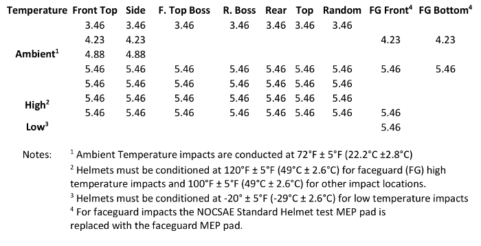 Table 1: Football helmet drop test matrix showing required impacts by drop velocity (m/sec) and impact location. (Table modified from NOCSAE DOC. 002-13m13) Please click here to view a larger version of this figure.
Representative Results
A detailed quantitative analysis of the results for this methodology was presented by Rush et al.(submitted) A synopsis of the results and the associated effectiveness of a coupled faceguard-shell helmet testing methodology is displayed in drop test results using Rawlings Quantum Plus, Riddell 360, Schutt Ion 4D, and Xenith X2 helmets as examples. Each of these helmets (of size "large") with faceguards displayed different results when compared to helmets without the faceguards. Figure 3 comparatively plots the SI values of each example helmet with and without the faceguard for the Front Top, Front Top Boss, Top, Side, Rear, and Rear Boss impact locations at an impact velocity of 5.46 m/s. While the mean SI value for each of these three consecutive impacts (90 ± 15 s) was well below the NOCSAE 1,200 SI threshold, each helmet displayed a unique location-dependent response when the faceguard was attached. Table 2 further illustrates the significance of these same impact tests by displaying Mean Differences (MD) with Root Squared Errors (RSE) for the Head Injury Criterion (HIC), Severity Index (SI), and peak resultant acceleration (G's) values for with and without faceguard configurations. Here, a least squares regression by Analysis of Variance was used for P-value calculations showing significant differences (p <0.05) for helmets with and without faceguards attached during testing. In addition to changes in HIC, SI, and Peak G, differences in impulsive responses were observed when the faceguards were added to these helmet examples. Figure 4 displays drop test results of the Xenith X2 helmet with faceguard and without faceguard at 4.88 m/s, showing a difference in acceleration-time history profile for each measured axis (X, Y and Z). It was also observed that the results were strongly dependent on helmet type, impact location, and impact velocity.
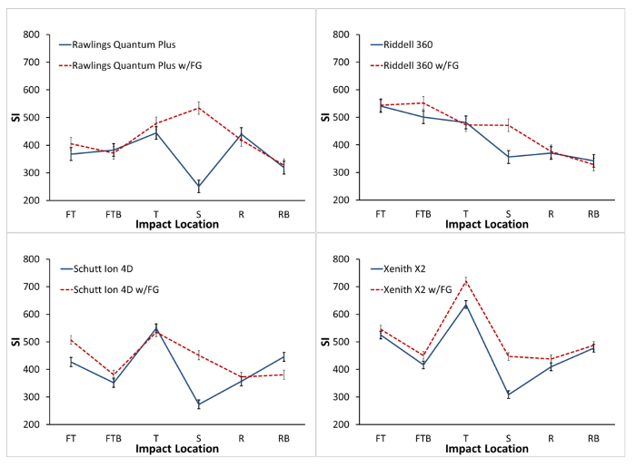 Figure 3: Drop test. Representative drop test results of Rawlings Quantum Plus, Riddell 360, Schutt Ion 4D, and Xenith X2 helmets at 5.46 meters per second; showing Severity Index (SI) per impact location for without faceguard (NOCSAE Standard) and with faceguard (w/FG) helmet configurations with Standard Error. Note: FG Front and FG Bottom direct faceguard impacts are not shown. Please click here to view a larger version of this figure.
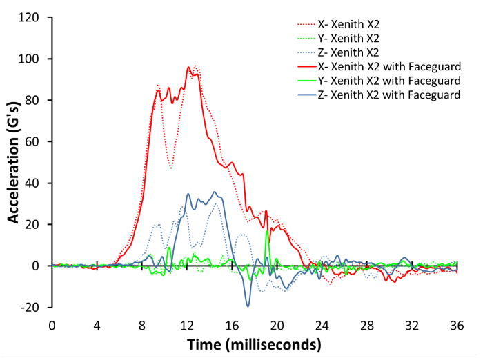 Figure 4:NOCSAE drop test. Results of the Xenith X2 helmet (Top) with faceguard and without faceguard at 4.88 m/s, showing a difference in acceleration-time history profile for each measured axis (X, Y and Z). Please click here to view a larger version of this figure.
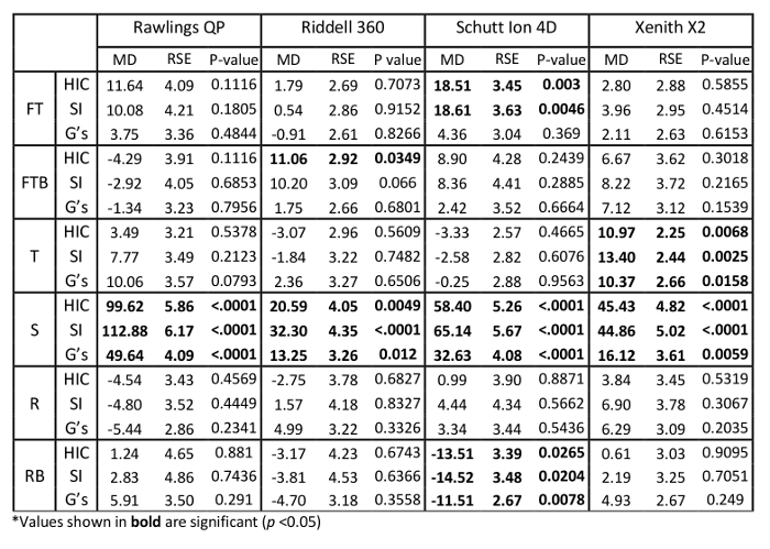 Table 2: Representative drop test. Results of Rawlings Quantum Plus, Riddell 360, Schutt Ion 4D, and Xenith X2 helmets at 5.46 m/s. Showing Mean Difference (MD) in Head Injury Criterion (HIC), Severity Index (SI), and peak resultant acceleration (G's) values for with and without faceguard configurations across Front Top (FT), Front Top Boss (FTB), Top (T), Side (S), Rear (R), and Rear Boss (RB) impact locations. Note: Displayed values represent Mean Differences and Root Squared Errors (RSE) in respect to the without faceguard configuration for three consecutive impacts with intervals 90 ± 15 s. Please click here to view a larger version of this figure.
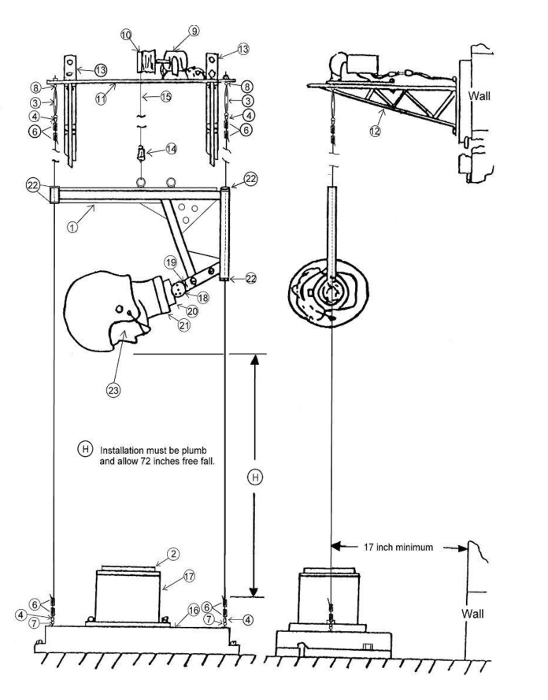 Figure 5: Schematic of twin-wire drop test rig. The schematic shows each component of the mechanical assembly with instillation constraints. Each component is denoted with a number corresponding with a part description as identified in the list of Materials. Refer to the list of Materials. (Image from NOCSAE DOC. 001-13m15b) Please click here to view a larger version of this figure.
Discussion
The reported methodology that couples NOCSAE football helmet and faceguard drop impact tests offers a unique technique to assess better performance characteristics of modern football helmets. The most critical steps for evaluating this better performance characteristic of modern football helmets are the following: 1) correctly setting up the mechanical test device; 2) accurately conducting calibration procedures; and 3) properly attaching the helmet/faceguard to the headform.
This methodology requires proper test setup and calibration procedures. There is inherent variability between each NOCSAE headform due to limitations in the manufacturing process, which include porosity in the polymeric materials. NOCSAE combats this unique variability by a normalization process via headform calibration procedures using and annually recertified calibration MEP pad. Thus, it is ever more important that additional variation is not introduced by ensuring that the mechanical test assembly is properly and securely maintained. Before testing, it is important the threaded headform collar and headform rotator and drop carriage bolts are checked and securely tightened. Helmet-headform positioning and chinstrap fit should be checked prior to every drop test. During impact, the helmet may shift, which is acceptable but may need to be adjusted.
In addition to testing the setup and calibration procedures, impact testing requires proper helmet preparation. Faceguard selection and correct attachment of helmet/faceguard to the headform is a critical part of the test procedure. For general helmet testing, a baseline faceguard model should be selected and securely attached with all faceguard specific hardware. Typically a baseline faceguard is defined as one that offers the minimal amount of facial protection, not including kicker-style faceguards. Due to the variability in modern helmet design and the added constraints of the faceguard component, additional procedures may be required for proper helmet-headform attachment. Generally, faceguards should be securely attached to the helmet prior to insertion onto the headform. Some helmets may require partial attachment of the faceguard to the helmet that is then secured upon helmet-headform insertion. A light application of talcum powder to the headform may aid in helmet attachment. For other troubleshooting refer to the NOCSAE troubleshooting guide for test equipment and impact testing (ND.087-12m14).
The test procedure required modification of NOCSAE standard impact locations, in order to account for the addition of the faceguard during testing. The impact locations for the present drop tower tests include replacement of the NOCSAE standard Front and Front Boss with the Front Top and Front Top Boss impact locations and inclusion of Faceguard Front and Faceguard Bottom locations. Figure 3 shows the SI levels at different impact locations including the two new proposed ones. For example, the Riddell data, shown in Figure 3, illustrates the point that the two new locations incur the greatest SI levels, which otherwise would not have been known since these two new tests have not been required for the NOCSAE certification. Initial testing determined that the Front Top and Front Boss were better suited impact sites since they would impact the helmet shell rather than the faceguard. These sites would be more realistic by allowing direct shell-liner impacts while still including the constraints of the faceguard component. Direct faceguard impacts were achieved by including the Faceguard Front and Faceguard Bottom impacts, which were identical to the prescribed impact locations for NOCSAE football faceguard certification tests. The inclusion of these two impacts allowed for a unified football helmet and faceguard drop test procedure. These faceguard impacts required exchanging of the test MEP with the faceguard MEP and additional environmental conditioning procedures, as portrayed in Table 1.
Representative drop test results show that football helmets should have faceguards attached during testing. Comparative drop test results revealed that the faceguard adds a stiffening kinematic constraint to the shell that lessens total energy absorption. Figure 3 and Table 2 show differences in the SI levels across impact locations for helmets in the NOCSAE standard (without faceguard) and the modified with faceguard configurations. As compared to the current NOCSAE test method, football helmets tested with the faceguard attached shows unique responses that are dependent on helmet type, which may vary by impact location. The differences in these responses can be accredited to the shell- faceguard couplings, which are dependent on unique design features of the helmet being tested. The Rawlings Quantum Plus, Riddell 360, Schutt Ion 4D and Xenith X2 helmets were used for representative results, as these helmets characterize some of the newest innovations in helmet technology. Each of these helmets vary significantly by their unique design features including faceguards, faceguard attachment systems, chinstrap attachment systems and liner systems. As displayed in Table 2, these representative results show significant variations (p < 0.05) in HIC, SI, and peak acceleration values that are dependent on helmet type, impact location and the faceguard configuration. Additionally, differences in acceleration-time history profile were also observed. An example of such a response can be seen in Figure 4, where the triaxial acceleration response (for X, Y and Z axes) of the Xenith X2 helmet at a 4.88 m/sec Top impact displayed a 40 G dip in the X axis acceleration when the faceguard was not attached. Due to the additional constraint that the faceguard brings to the helmet shell, the acceleration dip was nonexistent for the same impact when the faceguard was attached to the shell. More specifically, when the faceguard was not included, the polycarbonate shell near the impact point could flex more and thus absorb more energy. When the faceguard was included, the polycarbonate shell would not flex as much. The inclusion of the faceguard during impact testing is intended to more accurately mimic on-field loading conditions.
Our proposed test method uses a more stringent certification limit as compared to the current NOCSAE standard. In our proposed test method for all 5.46, 4.88, and 4.23 m/s impacts, we recommend that the NOCSAE committee create a new safe lower SI level based on Hodgson et al. (1970) work.
If any resulting SI value for any one impact is greater than these respective thresholds, then the test is determined to be a failure. Representative results (Figure 3) show that SI values for 5.46 m/s of all helmets tested in this study fall well below the current 1,200 SI NOCSAE pass/fail criterion for such impacts. Additional injury metrics of HIC and peak resultant acceleration are included in Table 2, yet no certification limits were given on these metrics. Future helmet certification limits should investigate employment of multiple injury metric pass/fail criteria.
The final factor for an improved helmet test standard would be to publish standard test results in a manner that would allow a player to make an informed decision on helmet selection. For many players, appearance is often the most important factor when selecting a football helmet/faceguard combination. Heavier grill-type faceguard are also becoming more dominant on the football field today presumably for this reason. These heavier faceguards shift the center of gravity of the athletes head and add an extra moment arm inducing a more deleterious torque during oblique helmet to helmet impacts. Thus, it is ever more important to understand the systematic response of helmets and for the player to know how these heavier faceguards affect helmet performance. Future helmet certification should require manufacturers to display size and faceguard-specific helmet test results.
These reported test procedures serve as an effective solution that allows the ability to assess better performance characteristics of current and future football helmet systems. The test method defined herein is intended to be a modification to the current NOCSAE twin-wire drop test procedure, which inherently limits performance testing of headgear to linear acceleration-based injury criteria. While currently in-use and readily available, this twin-wire test device cannot measure angular acceleration. As compared to the existing methods, this reported football helmet test method gives a more accurate representation of a helmet's performance and its ability to mitigate on-field impact.
Disclosures
The authors have nothing to disclose.
Acknowledgments
The authors would like to acknowledge the Center for Advanced Vehicular Systems (CAVS) at Mississippi State University for providing testing facilities and Rush Sports Medical of Meridian, Mississippi for their monetary support.
References
- Langlois JA, Rutland-Brown W, Wald MM. The epidemiology and impact of traumatic brain injury: a brief overview. J Head Trauma Rehabil. 2006. pp. 375–378. [DOI] [PubMed]
- Broglio SP, et al. Head impacts during high school football: a biomechanical assessment. J Athl Train. 2009;44:342–349. doi: 10.4085/1062-6050-44.4.342. [DOI] [PMC free article] [PubMed] [Google Scholar]
- Broglio SP, Martini D, Kasper L, Eckner JT, Kutcher JS. Estimation of head impact exposure in high school football: Implications for regulating contact practices. Am. J. Sports Med. 2013;41:2877–2884. doi: 10.1177/0363546513502458. [DOI] [PMC free article] [PubMed] [Google Scholar]
- Costanza A, et al. Review: Contact sport-related chronic traumatic encephalopathy in the elderly: clinical expression and structural substrates. Neuropathol Appl Neurobiol. 2011;37:570–584. doi: 10.1111/j.1365-2990.2011.01186.x. [DOI] [PMC free article] [PubMed] [Google Scholar]
- McKee AC, Cantu RC, Nowinski CJ, Hedley-Whyte ET, Gavett BE, Budson AE, Santini VE, Lee HS, Kubilus CA, Stern RA. Chronic traumatic encephalopathy in athletes: progressive tauopathy after repetitive head injury. J. Neuropathol Exp Neurol. 2003. pp. 709–735. [DOI] [PMC free article] [PubMed]
- Bartsch A, Benzel E, Miele V, Prakash V. Impact test comparisons of 20th and 21st century American football helmets: Laboratory investigation. J Neurosurg. 2012;116:222–233. doi: 10.3171/2011.9.JNS111059. [DOI] [PubMed] [Google Scholar]
- NOCSAE. Standard Performance Specification for Newly Manufactured Football Helmets. 2013. Paper No. 002-13m13.
- Greenwald RM, Gwin JT, Chu JJ. Head Impact Severity Measures for Evaluating Mild Traumatic Brain Injury Risk Exposure. Neurosurg. 2008;62:789–798. doi: 10.1227/01.neu.0000318162.67472.ad. [DOI] [PMC free article] [PubMed] [Google Scholar]
- Newman JA. In: Accidental Injury: Biomechanics and Prevention. Yoganandan N, editor. Springer; 2015. [Google Scholar]
- Newman JA, Shewchenko N, Welbourne E. A proposed new biomechanical head injury assessment function - the maximum power index. Stapp Car Crash J. 2000;44:215–247. doi: 10.4271/2000-01-SC16. [DOI] [PubMed] [Google Scholar]
- Gadd CW. Use of a weighted-impulse criterion for estimating injury hazard. SAE Technical Papers. 1966.
- Lissner HR. Experimental Studies on the Relation Between Acceleration and Intracranial Pressure Changes in Man. Surgery, Gynecology and Obsterics. 1960;III:329–338. [PubMed] [Google Scholar]
- Gurdjian ES, et al. Concussion - Mechanism and Pathology. Proceedings of the Seventh Strapp Car Crash Conference.1963. [Google Scholar]
- Patrick LM, et al. Survival by Design - Head Protection. The Seventh Strapp Car Crash Conference.1963. [Google Scholar]
- Versace J. A review of the Severity Index. SAE Technical Papers. 1971.
- Newman J, et al. A new biomechanical assessment of mild traumatic brain injury. Part 2. Results and conclusions. Proceedings of International Research Conference on the Biomechanics of Impacts. 2000. pp. 223–233.
- NOCSAE. Standard Performance Specification for Newly Manufactured Football Helmets. 2011. Paper No. 002-11m11a.
- NOCSAE. Standard Test Method and Equipment used in Evaluating the Performance Characteristics of Protective Headgear/Equipment. 2015. Paper No. 001-11m15.
- NOCSAE. Standard Method of Impact Test and Performance Requirements for Football Faceguards. 2011. Paper No. ND087-11M11.
- NOCSAE. Standards and Process. 2013.
- Gwin JT, et al. An investigation of the NOCSAE linear impactor test method based on in vivo measures of head impact acceleration in American football. J Biomech Eng. 2010;132 doi: 10.1115/1.4000249. [DOI] [PubMed] [Google Scholar]
- NOCSAE. Standard Performance Specification for Newly Manufactured Lacrosse Helmets with Faceguards. 2013. NOCSAE DOC (ND) 041-11m12.
- Hodgson VR, Thomas LM, Prasad P. Testing the validity and limitations of the severity index. SAE Technical Papers. 1970.
- NOCSAE. Manufactureers Procedural Guide for Product Sample Selection for Testing to NOCSAE Standards. 2014. Paper No. 011-13m14d.
- NOCSAE. Standard Method of Impact Test and Performance Requirements for Football Faceguards. 2014. Paper No. 087-12M14.
- NOCSAE. Troubleshooting Guide for Test Equipment and Impact Testing. 2014. Paper No. ND100-96M14.
- NOCSAE. Equipment Calibration Procedures. 2014. Paper No. 101-00m14a.
- Diversified Technical Systems. 2014. Source: http://www.dtsweb.com.


