Abstract
Zebrafish embryos offer an ideal experimental system to study complex morphogenetic processes due to their ease of accessibility and optical transparency. In particular, posterior body elongation is an essential process in embryonic development by which multiple tissue deformations act together to direct the formation of a large part of the body axis. In order to observe this process by long-term time-lapse imaging it is necessary to utilize a mounting technique that allows sufficient support to maintain samples in the correct orientation during transfer to the microscope and acquisition. In addition, the mounting must also provide sufficient freedom of movement for the outgrowth of the posterior body region without affecting its normal development. Finally, there must be a certain degree in versatility of the mounting method to allow imaging on diverse imaging set-ups. Here, we present a mounting technique for imaging the development of posterior body elongation in the zebrafish D. rerio. This technique involves mounting embryos such that the head and yolk sac regions are almost entirely included in agarose, while leaving out the posterior body region to elongate and develop normally. We will show how this can be adapted for upright, inverted and vertical light-sheet microscopy set-ups. While this protocol focuses on mounting embryos for imaging for the posterior body, it could easily be adapted for the live imaging of multiple aspects of zebrafish development.
Keywords: Developmental Biology, Issue 119, Live imaging, zebrafish, mounting, confocal, light-sheet, development
Introduction
Posterior body elongation is an essential process in embryonic development by which the embryo extends to form a large part of the body axis. It is an example of a complex morphogenetic process by which multiple cell behaviors act coordinately to generate the morphogenesis at the level of individual tissues. These differential tissue deformations then act together to generate the elongation of the posterior body at the whole structure level. To understand how these processes are controlled and coordinated during development, we must be able to follow these processes at multiple scales (i.e. at the level of molecules, cells, cell populations and tissues) and to relate this directly to the morphogenesis of the entire structure.
Zebrafish embryos are ideal for imaging posterior body elongation as their optical transparency and small size allows for the application of minimally invasive light imaging approaches well suited to live imaging.1 This has been evidenced by a series of recent publications that have shed light on posterior body development at the level of molecules,2 single cells,3 and inter-tissue behaviors,4 as well as at the level of cell population and whole organ.5
Advanced imaging techniques such as confocal, multi-photon microscopy and selective plane illumination microscopy (SPIM) are enabling the long term imaging of developmental processes with decreased effect of light toxicity and photo-bleaching. Robust techniques for the mounting of live samples are required to achieve three goals: 1) sufficient support to maintain samples in the correct orientation during transfer to the microscope and during acquisition, 2) sufficient freedom of movement of the sample to allow for the outgrowth of the posterior body region without affecting its normal development, and finally 3) a certain degree in versatility of the mounting method to allow imaging on diverse imaging set-ups.
This protocol introduces a mounting technique for imaging the development of the zebrafish D. rerio. This technique involves mounting embryos such that the head and yolk sac regions are almost entirely included in agarose, while leaving the posterior body region to elongate and develop normally. As such, it is also an appropriate method for the long-term imaging of other regions of the developing body as the agarose enables imaging by standard light imaging techniques. This protocol demonstrates mounting of embryos in a lateral orientation, although it is also possible to mount embryos in alterative orientations. It will further show how to adapt the method for upright, inverted and vertical light-sheet microscopy setups.
Protocol
1. Preparation of Solutions and Pulled Glass Needle
Make a 25x stock solution of Tricaine (3-amino benzoic acid ethyl ester, also called ethyl 3-aminobenzoate) at 4 mg/mL in 20 mM Tris pH 8.8 and bring that solution is at pH 7. Aliquot by 4 mL and store at -20 °C. NOTE: The anesthetic Tricaine acts preferentially on neural voltage-gated sodium channels thereby blocking muscle twitching and movement6.
Make a working solution of Tricaine at a final concentration of 0.17 mg/ml in E3 embryo medium.7 NOTE: Make the Tricaine working solution extemporaneously as the pH of this solution drifts.
Dissolve the low melting point agarose to a final concentration of 1.5% in E3 embryo medium in a 50 mL tube by heating the solution in a microwave. Let this solution equilibrate to 42 - 45 °C in either a water bath or bench-top incubator. If preparing large dishes for vertical light-sheet imaging (step 4), make an additional 25 mL of 1% standard melting agarose in E3 embryo medium.
Use borosilicate glass with filament capillaries with dimensions of OD 1.20 mm, ID 0.69 mm, length 10 mm.
If capillaries are pulled on the type of heating-filament needle puller described in the Table of Equipment and Reagents, use the following settings: Heat 600, Pull 120, Velocity 50, Time 225, Pressure 500. With a pair of sharp forceps, break the needle just past the point at which it flexes to create a clean and sharp needle for orientating embryos and removing excess agarose. A micro-scalpel can also be used to remove excess agarose.
2. Embedding of Embryos for Inverted or Upright Microscopy
Raise the embryos up to the appropriate stage in E3 embryo medium.7
At the required stage, dechorionate embryos with a pair of sharp forceps underneath a binocular dissecting microscope.
Incubate the dechorionated embryos for at least 5 min in the Tricaine working solution.
Once the melted agarose solution has cooled to 45 °C, use a glass Pasteur pipette to transfer the dechorionated embryo directly into the 50 ml tube with minimal transfer of E3 medium.
Remove embryo together with approximately 1 ml of mounting medium and add approx. 100 µl of mounting medium together with the embryo to the central circle of a 35 mm glass-bottomed petri dish with a 10 mm microwell.
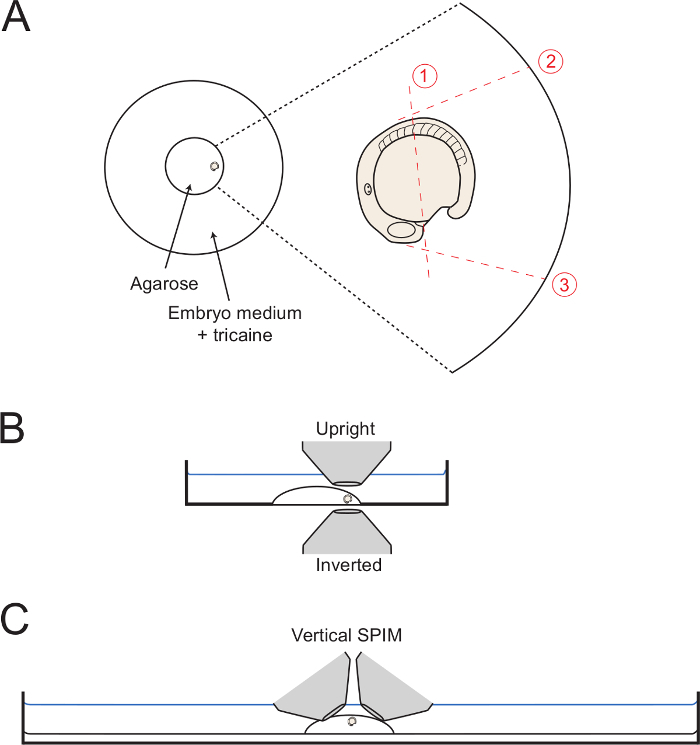
As the mounting medium is setting, move the embryo to the edge of the circle of agarose with the tail facing outwards (Figure 1A). Use the capillary needle to maintain the embryo in the desired lateral orientation until the gel is completely set. To image posterior body development, take care to orientate the embryo in as lateral an orientation as possible. Therefore, maintain the embryo in this position by careful adjustments with the capillary needle. NOTE: Multiple embryos can be added to the mounting dish at this point, if required. If this is the case, transfer the low-melt agarose into the dish first and add the embryos to the center of the agarose drop. Then, push the embryos out to the edges of the glass ring and orientate into the desired position. Up to six embryos can be mounted this way before the agarose becomes solidified.
3. Removal of Excess Agarose Around the Posterior Body
NOTE: This section describes the procedure by which agarose is removed from the region surrounding the posterior body. In the case of posterior body elongation, it is important to ensure that the tail can grow-out normally. By removing the agarose after the embryo has been completely included by agarose, the embryo is left enclosed by the head region and approximately half of the yolk sac.
Once the agarose drop has set, flood the petri dish with the Tricaine working solution.
Under a dissecting binocular microscope with a transmitted-light base, adjust the mirror position and angle of incident light such that the strong contrast allows for the cuts in the agarose to be seen clearly through the operation.
To perform cut 1 (Figure 1), use the capillary needle or the micro-scalpel to cut the agarose mid-way along the yolk, from a position just posterior to the forming heart field to the position of the somite 5 (the 5th anterior somite).
Start the initial cut adjacent to the forming heart as shown, and the full way through the agarose to the glass.
Keep the capillary or micro-scalpel deep within the agarose, and slowly saw up and down while beginning to make a long cut over the embryo as shown Figure 1. Cut as close to the embryo as possible without puncturing the embryo or yolk.
Next, make cuts 2 and 3 (Figure 1), starting from the position against the embryo and with the cut going all the way down to the glass bottomed dish. Make cut 2 so that it is tangential to the first 5 somites, allowing for full dorsalward unfolding of the posterior body. Make cut 3 at a 90° angle with the yolk surface and starting from the heartfield. NOTE: Cutting the agarose until the edge of the glass circle (as shown in Figure 1) aids in removing the agarose as a complete block (step 3.6). However, this is not necessary.
Starting at the intersection of cuts 1 and 3, make a slow diagonal cut towards the end of cut 2 whilst slowly lifting upwards in order to dislodge the square of agarose surrounding the posterior body. Notes: In some cases, this will be released in one block and the operation is completed in one go. In others, it may take several attempts to dis-lodge all the agarose surrounding the embryo.
With a pair of sharp forceps, remove the dislodged blocks of agarose from the embryo medium. To aid in this process, move the agarose pieces to the side of the dish and use the wall of the petri dish as support whilst lifting out the agarose pieces.
 Figure 1: Diagrams of Mounting Set-ups. (A) The diagram shows the position of the mounted embryo within the center glass ring of a petri dish. On the right is a zoom of the embryo with each successive cut through the surrounding agarose shown with dottted red lines. (B) The mounted embryos is diagrammed in lateral view displaying the ease of access for both inverted and upright objectives. (C) A similar digram showing how embryos can be mounted for vertical light sheet imaging set-ups. Please click here to view a larger version of this figure.
If muscle twitching is not completely blocked at that point, add drops of Tricaine from the stock solution of 4 mg/ml, pH 7.
4. Mounting of Embryos for Vertical Light-sheet Microscopy
NOTE: This is a variation on the method outlined above that allows for the access of multiple objectives for imaging of samples by vertically-orientated SPIM. The idea behind this variation is to lift the sample slightly higher than the bottom of the dish, to allow for easy access of two imaging objectives.
Prior to sample mounting, coat a 100 mm plastic petri dish with 1% agarose in E3 medium to a height of 5 mm and allow to set.
Place a drop of 1 ml low-melting point agarose to the center of the dish and allow to set.
Embed embryos in low-melting point agarose as in section 2. However, this time, remove the embryo from the 50 ml tube of agarose with a smaller drop of solution (0.5 ml) and place this small drop on top of the 1 ml drop in the center of the dish.
Use the capillary needle to place the embryo in the center of the small drop and maintain its correct orientation until gel is set.
Flood the dish with Tricaine working solution and remove the excess agarose as in section 3 but without cutting through the cushion of 1% standard agarose.
Representative Results
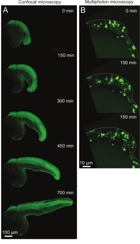
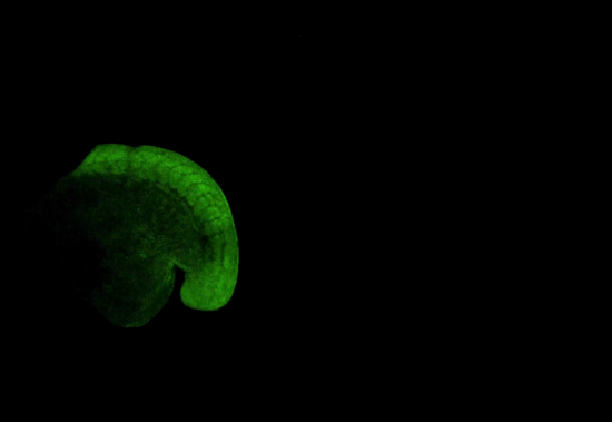
The protocol outlined above details a versatile technique for the mounting of zebrafish embryos for long-term time lapse imaging. An example of this is shown in Figure 2A and in animated/video Figure 1. Embryos were injected at the 1 cell stage with mRNA encoding the photoconvertible fluorescent protein kikumeGR. At the 15 somite stage they were mounted as described above and imaged for 12 hr on an inverted confocal microscope with a 10X objective. The resulting confocal stacks were maximally projected to be displayed as shown. This movie clearly shows that the posterior body is allowed to move freely throughout the duration of the movie and shows similar changes in morphology as seen in embryos that are allowed to develop freely of their chorion in normal culture conditions.
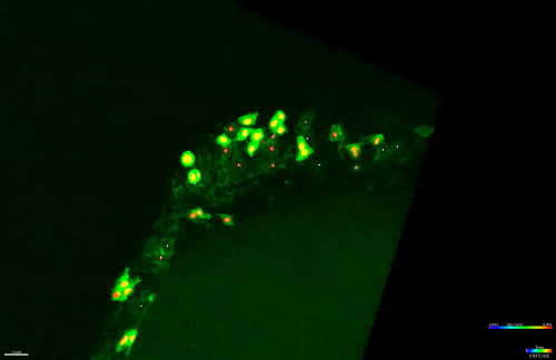
An additional example is shown in Figure 2B and animated/video Figure 2. Here, embryos were injected at the 16 cell stage with a combination of mRNAs encoding histone 2B-mCherry protein (that labels the nuclei) and eGFP:CAAX box (that labels membranes; for details see reference5). They were then imaged on an upright multiphoton microscope with a water immersion 25X objective as diagrammed in Figure 1B. Images were taken for 3 hr from the 10 somite stage in order to visualize cellular behaviors during tailbud formation. Cells can be seen to be generating active protrusions and directional movements as the tailbud forms normally.
 Figure 2: Examples of Time-lapse Imaging of Posterior Body Elongation at 10X Magnification. (A) Consecutive frames of a representative movie covering the process of axial elongation. Embryos are shown in lateral view with posterior to the right side of the image. (B) Consecutive frames of a higher magnification movie showing individual cell behaviors during tailbud formation. Embryos are shown in lateral view with posterior to the right. Dotted lines outline the forming tailbud. Small colored lines show tracks of nuclei to follow individual cell movements. Please click here to view a larger version of this figure.
 Animated/Video Figure 1: Time-lapse Movie of Posterior Body Elongation of a KikumeGR mRNA Injected Zebrafish Embryo by Confocal Microscopy. Embryo is shown with anterior to the left and posterior to the right. Images were taken at 10 min intervals at 10X magnification. Please click here to view a larger version of this figure.
 Animated/Video Figure 2: Time-lapse Movie of Posterior Body Elongation of a Nuclear-mCherry and Membrane-GFP Labelled Zebrafish Embryo Imaged by Two-photon Microscopy. Embryo is shown with anterior to the right and posterior to the left. Images were taken at 2 min intervals at 25X magnification. Colored lines display tracks of cells for the last ten time-steps for each tracked cell. Please click here to view a larger version of this figure.
Discussion
This mounting technique enables embryos to be kept still during transfer to the microscope and over long-term time-lapse imaging experiments aimed at following posterior body elongation at multiple length scales. Furthermore, it is versatile in that it allows for imaging on both upright and inverted microscopy set-ups, and a suggestion is made for how this can be further adapted to vertically orientated SPIM.
A critical step in this protocol is the careful removal of excess agarose surrounding the posterior body that is important for allowing the normal development of this structure. It is important to take care here in not damaging the embryo, particularly when removing the agarose around the top of the yolk. In addition, care must be taken when removing the cut agarose block from around the embryo, as sometimes it is possible to lose the embryo from the mold during this process. For these reasons, this is a low-throughput method that is not suitable for the mounting of many zebrafish embryos simultaneously, in contrast to already published methods utilizing 3D printed plastic molds.8,9 However, embryos are highly stable by this mounting method and therefore can be transported to the microscope much easier, and retain their 3D orientation throughout posterior body elongation.
Another critical step is the accuracy of the initial lateral orientation of the embryo, avoiding any antero-posterior or dorso-ventral tilt. Either tilt will preclude the lateral vision of the posterior body extension, which is the most convenient angle of view for further analysis. The antero-posterior tilt will in addition result in the posterior body growing up or down with respect to the horizontal plane, which will mean the acquisition of higher stacks in z and thus time-lapses with a lower time resolution.
This method is versatile and has allowed for imaging of cell division rates with the use of the Fucci line5,10 as well as multi-scalar morphometric analyses.5 However, given the dramatic overall displacement of the tailbud during the elongation of the posterior body axis, only relatively low magnification objectives can be used to capture the entire process such as shown in Figure 2. This is because higher magnification results in the region of interest leaving the field of view within 3 - 4 hr of acquisition (Video Figure 1). Therefore, one way to further improve the imaging of the tailbud is to have an automated tracking algorithm that can track the overall movement of the tailbud and adjust the x,y,z position of the microscope stage during acquisition. Given the increased stability of the embryo in all axial dimensions with the mounting method described here, it should be amenable to such an approach.
Disclosures
The authors have nothing to disclose.
Acknowledgments
Estelle Hirsinger: Core funding from the Institut Pasteur and Agence Nationale de la Recherche (ANR-10-BLAN-121801 DEVPROCESS). Estelle Hirsinger is from the Centre National de la Recherche Scientifique (CNRS). Benjamin Steventon was funded by the Agence Nationale de la Recherche (ANR- 10-BLAN-121801 DEVPROCESS), then a Roux fellowship (Institut Pasteur) then an AFM-Téléthon fellowship (number 16829). He is now supported by a Wellcome Trust/Royal Society Sir Henry Dale Fellowship.
References
- Graeden E, Sive H. Live Imaging of the Zebrafish Embryonic Brain by Confocal Microscopy. J Vis Exp. 2009. pp. e1–e2. [DOI] [PMC free article] [PubMed]
- Delaune EA, François P, Shih NP, Amacher SL. Single-Cell-Resolution Imaging of the Impact of Notch Signaling and Mitosis on Segmentation Clock Dynamics. Dev Cell. 2012;23(5):995–1005. doi: 10.1016/j.devcel.2012.09.009. [DOI] [PMC free article] [PubMed] [Google Scholar]
- Lawton AK, et al. Regulated tissue fluidity steers zebrafish body elongation. Development. 2013;140(3):573–582. doi: 10.1242/dev.090381. [DOI] [PMC free article] [PubMed] [Google Scholar]
- Dray N, et al. Cell-Fibronectin Interactions Propel Vertebrate Trunk Elongation via Tissue Mechanics. Curr Biol. 2013;23(14):1335–1341. doi: 10.1016/j.cub.2013.05.052. [DOI] [PMC free article] [PubMed] [Google Scholar]
- Steventon B, et al. Species tailoured contribution of volumetric growth and tissue convergence to posterior body elongation in vertebrates. Development. 2016;143:1732–1741. doi: 10.1242/dev.126375. [DOI] [PubMed] [Google Scholar]
- Attili S, Hughes SM. Anaesthetic Tricaine Acts Preferentially on Neural Voltage-Gated Sodium Channels and Fails to Block Directly Evoked Muscle Contraction. PLoS ONE. 2014;9(8):103751–103756. doi: 10.1371/journal.pone.0103751. [DOI] [PMC free article] [PubMed] [Google Scholar]
- Westerfield M. The Zebrafish Book, 5th Edition; A guide for the laboratory use of zebrafish (Danio rerio) Eugene: University of Oregon Press; 2007. Paperback. [Google Scholar]
- Schröter C, et al. Dynamics of zebrafish somitogenesis. Dev Dyn. 2008;237(3):545–553. doi: 10.1002/dvdy.21458. [DOI] [PubMed] [Google Scholar]
- Megason SG. In toto imaging of embryogenesis with confocal time-lapse microscopy. Methods Mol Biol (Clifton, N.J.) 2009;546:317–332. doi: 10.1007/978-1-60327-977-2_19. Chapter 19. [DOI] [PMC free article] [PubMed] [Google Scholar]
- Sugiyama M, et al. Illuminating cell-cycle progression in the developing zebrafish embryo. PNAS. 2009;106(49):20812–20817. doi: 10.1073/pnas.0906464106. [DOI] [PMC free article] [PubMed] [Google Scholar]


