Abstract
Ventricular assist devices (VAD) became in recent years the standard of care therapy for advanced heart failure with hemodynamic compromise. With the steadily growing population of device recipients, various post-implant complications have been reported, mostly associated with the hyper-shear generated by VADs that enhance their thrombogenicity by activating platelets. While VAD design optimization can significantly improve its thromboresistance, the implanted VAD need to be evaluated as part of a system. Several clinical studies indicated that variability in implantation configurations may contribute to the overall system thrombogenicity. Numerical simulations were conducted in the HeartAssist 5 (HA5) and HeartMate II (HMII) VADs in the following implantation configurations: (i) Inflow cannula angles – 115° and 140° (HA5); (ii) three VAD circumferential orientations: 0°, 30° and 60° (HA5 and HMII); and (iii) 60° and 90° outflow graft anastomotic angles (AA) with respect to the ascending aorta (HA5). The stress accumulation of the platelets was calculated along flow trajectories and collapsed into a probability density function (PDF), representing the “thrombogenic footprint” (TF) of each configuration- a proxy to its thrombogenic potential (TP). The 140° HA5 cannula generated lower TP independent of the circumferential orientation of the VAD. 60° orientation generated the lowest TP for the HA5 versus 0° for the HMII. An AA of 60° resulted in lower TP for HA5. These results demonstrate that optimizing the implantation configuration reduces the overall system TP. Thromboresistance can be enhanced by combining VAD design optimization with the surgical implantation configurations for achieving better clinical outcomes of implanted VADs.
Keywords: Ventricular assist device, Implantation configuration, CFD
Introduction
Mechanical circulatory support (MCS) has emerged as a mainstay of therapy for failing patients with advanced New York Heart Association (NYHA) Class III and IV (American Heart Association (AHA) Stage C and D) heart failure.1,2 Specifically, ventricular assist devices (VADs) have emerged as the dominant MCS device implanted, either in a single or dual ventricular configurations, i.e., left ventricular assist device (LVAD) or BiVAD, respectively.3–7 Several VADs are currently approved by the Food and Drug Administration (FDA) for bridge-to-transplant and as destination therapy. Despite the hemodynamic efficacy of VADs for restoring failing circulation, they remain plagued by a significant rate of adverse events (AEs).8–11 For instance, thrombosis,12 which may lead to a range of complications including thromboembolic events with frank stroke and other central nervous system and peripheral sequelae, intra-device thrombus accumulation, reduced pump output with potential complete pump stop.13–19 To prevent VAD-related thrombosis, anti-thrombotic agents – anti-platelet and anticoagulant medications, which to date have had only partial efficacy in limited thrombosis – are mandated to MCS patients;20,21 In fact, recent work has demonstrated mechanistic limitations of agents such as aspirin in limited VAD related thrombosis.22,23
A dominant contributing mechanism driving thrombosis in MCS systems is the supra-physiologic hypershear environment, i.e., highly dynamic elevated shear stress, imparted to blood by virtue of the propulsion means and geometries of current VAD systems.24,25 Specifically, present systems, being predominantly of continuous flow design, rotate at high speeds, with extremely narrow gap clearances between the impeller and the pump housing, inducing elevated shear stresses on platelets and red blood cells as they traverse the VAD, resulting in cumulative platelet damage with resultant platelet activation, hemolysis and initiation and propagation of thrombus formation.24–27 In an attempt to reduce shear-mediated platelet activation, device design optimization processes, e.g., Device Thrombogenicity Emulation (DTE) methodology,25,28 have successfully demonstrated their efficacy for enhancing the device thromboresistance.24,25,29 In addition, the efficacy of such methodology for reducing VAD thrombogenicity has been demonstrated overweighing typical pharmacological management in which current clinical agents in use.22,23
In considering an implanted VAD, the pump must be regarded as an element of a larger MCS system. Within the system, blood flow patterns may be significantly affected by specific implantation configuration geometries and orientations that may contribute to unwanted non-physiological flow, turbulence and elevated dynamic shear stresses. The final MCS system configuration in a given patient depends on variables ranging from the individual surgical technique to the patient-specific anatomy. For instance, the interface between the VAD and the heart that establishes the pump inflow conditions, the nature of the inflow cannula with its specific geometry and the angulation and radial orientation of the pump with respect to the ventricular apex.30 Furthermore, additional variables are introduced by the specific angulation of the outflow graft and the anastomotic angle of reconnection to the ascending aorta. The present study hypothesized that these system element variables (e.g., orientation and angulation) may adversely affect the overall thrombogenicity of the implanted MCS system, and such impact were evaluated by utilizing in silico modeling. Specifically, the following surgical implantation and geometric design variables were studied: 1. Inflow cannula elbow angle – 115° and 140° – for the HeartAssist 5 VAD (HA5; MicroMed Cardiovascular, Inc.); 2. VAD rotational orientation – three circumferential orientations of 0°, 30° and 60°, with respect to the pump sagittal plane – for both the HA5 and HeartMate II (HMII; Thoratec corp., Pleasanton, CA); 3. Outflow graft orientation – anastomotic angles of 60° and 90° with respect to the ascending aorta.
Materials and Methods
Geometries and Mesh Preparation and Numerical Simulations
Ventricular Assist Devices and Inflow Cannulae
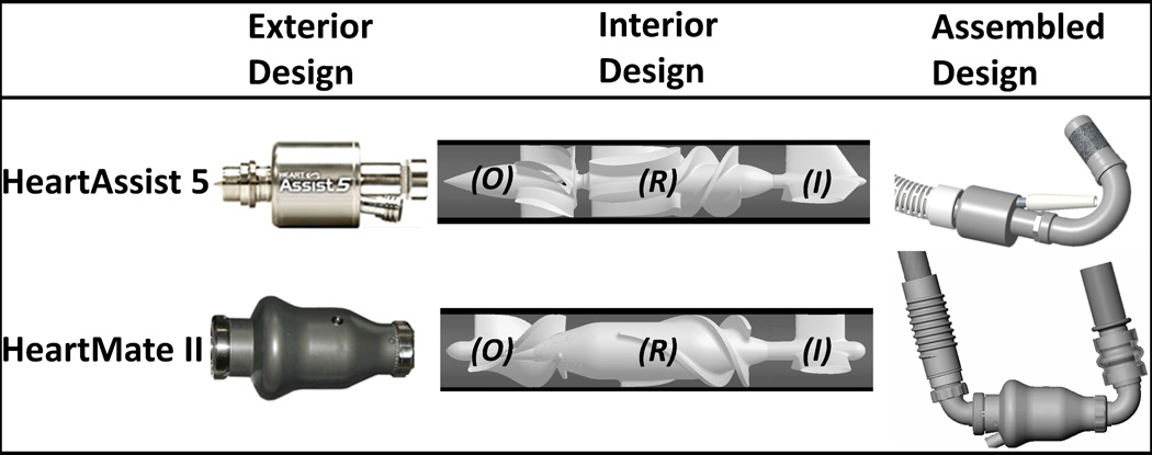
Two axial cfVADs (continuous flow VADs), HA5, for which device thrombogenicity was optimized in the previous studies,24,25 and HMII, were employed in the present study (Figure 1-Exterior). Both HA5 and HMII contain a three-straight-fin inflow stator (Figure 1-Interior-I), followed by the 3-to-6 (i.e., three and six blades corresponding to the first and the second stage of HA5 impeller) and 3 blades impellers for HA5 and HMII (Figure 1-Interior-R), respectively. Besides, these cfVADs’ impellers rotate in opposite directions, i.e., clockwise and counterclockwise of the flow directions for HA5 and HMII, respectively. Downstream of the impellers are the outflow stators which contain identical numbers of fins as the corresponding impeller blades (Figure 1-Interior-O). Both cfVADs connect to the apex of the left ventricle via their rigid elbow inflow cannulae; between the suturing ring and the elbow, HMII inflow cannula has a flexible section, while the HA5 inflow cannula is a rigid unit (Figure 1-Assembled; modified from MicroMed31 and John R., et al.32). The impact from such differences has been reported clinically as the flexibility of HMII inflow cannula may lead to post-implant device migration, and alter the implanted device geometry.30 The HA5 inflow cannula is directly inserted and oriented into the cored ventricular apex and the affixed suture ring is sewn to an apical fixation ring; in contrast, the HMII inflow cannula is inserted, oriented and secured to the inflow cuff which is affixed to the cored ventricular apex. Downstream of the outflow stators, the HMII has a rigid elbow outflow cannula which connects to the outflow graft; conversely, the HA5 outflow graft connects directly downstream of its outflow stator (Figure 1-Assembled). These surgical techniques afford the freedom for circumferential orientation for gaining a better individualized anatomical fit and orientation(Figure 2-B).
Figure 1.
The HA5 and HMII VADs. Both VADs share similar designs of inflow stator (I), rotor (R) and outflow stator (O).
Figure 2.
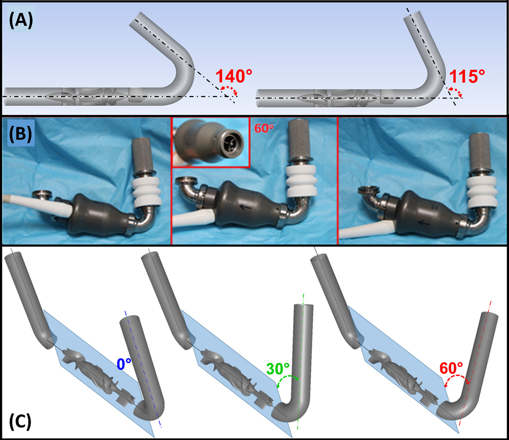
Implantation configurations studied: (A) Two inflow cannula elbow angles, 140° and 115° (HA5). (B) HMII- various inflow cannula circumferential orientations with respect to the inflow stator fins (inset). (C) Three inflow cannula circumferential orientations, 0° (blue), 30° (green) and 60° (red), with respect to the inflow stators (both VADs – shown here for HMII). The angles are indicated between the inflow cannulae and the sagittal plane (light blue).
Two HA5’s inflow cannula elbow angles, 115° and 140° (Figure 2-A), and three inflow cannula circumferential orientations, 0°, 30° and 60°for both HA5 and HMII (Figure 2-C) were studied. The HA5’s inflow cannula elbow angles were determined according to the manufacturer’s designs for adult and pediatric patients. The three inflow cannula circumferential orientations were determined according to the three-fin inflow stator design (120° radially apart), which generates a 60° of circumferential freedom when connecting the inflow cannula to the VAD due to the alignment of the elbow arm and the inflow stator fin. ANSYS DesignModeler and Meshing (ANSYS Inc., Canosburg, PA) was utilized for preparing geometries and the associated volumetric meshes. Mesh independence studies were conducted with various mesh densities (~12, 15 and 21M and ~13, 25 and 28M elements for HA5 and HMII, respectively), and were achieved with ~12 and 28M elements for HA5 and HMII, accordingly.
The FLUENT CFD solver (ANSYS, Inc.) was utilized for conducting fluid structure interaction (FSI) simulations, as described in the previous studies.24,33 Blood was modeled as two-phase Newtonian fluid (viscosity of 0.0035 kg/m-s and density of 1060 kg/m3), with platelets assumed as neutrally buoyant solid 3 µm diameter spheres. Sliding and stationary meshes were employed.24 Operating conditions of 9,000 rpm impeller speed were applied in both VADs, generating 4 and 5 L/min cardiac outputs (CO) in HA5 and HMII, respectively− serving as the parameters for the mass flow rate inlet boundary condition (BC), with 0 Pa initially applied as the pressure outlet BC.24
Approx. 32,000 platelets were seeded and released upstream of the inflow cannulae. The amount of platelets was determined to represent a typical physiological platelet count.24,33Optimized time steps of 70 and 18.5 µs were determined for HA5 and HMII, respectively,24,25 resulting in the corresponding degrees of the rotating impeller position per time step of 3.78 and 1 degrees for HA5 and HMII, accordingly.24,25
Outflow Graft Cannulation
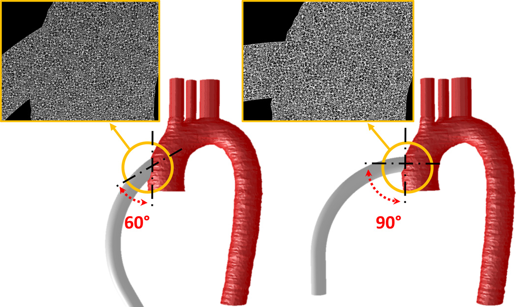
Human adult aorta geometry obtained from previous studies was employed (protocol approved by the Stony Brook University IRB).34 An open source software, ITK-SNAP,35 and ANSYS Gambit (ANSYS Fluent Inc., Lebanon, NH) were employed for reconstructing the CT images of aorta, and a geometry representing the outflow graft was connected to the ascending aorta with end-to-side anastomotic angles of 90° and 60°. The associated volumetric meshes were generated, and an optimized mesh density of approx. 5.5M elements was determined(Figure 3-insets).
Figure 3.
90° and 60° anastomotic angles of outflow graft end-to-side anastomosis with respect to the ascending aorta. The meshes at the anastomotic sites are presented in insets.
The CFD solver, ANSYS Fluent, was utilized for conducting the laminar transient simulations. The modeling blood property was described in the previous section. The inlet BC of the outflow graft employed the outflow velocity profile from the previous HA5 study – 9,500 rpm and 4 L/min of impeller speed and CO, respectively.25 A complex time dependent swirling flow, adapted from the literatures, was introduced as the inlet velocity BC at the aortic root to represent the last phase of the left ventricle contraction. Literature values were used to define flow rate at the brachiocephalic, left common carotid, left subclavian arteries and descending aorta.36,37 Approximately 26,000 platelets, which represented a typical physiological platelet count,24,33 were seeded and released upstream of the outflow cannulae. An optimized time step of 50 ms was determined, and approximately 90% of the platelets had a residence time of 1250 ms.
Stress Accumulation (SA) and Probability Density Function (PDF)
The shear loading histories of the platelet trajectories, stress accumulation (SA), were computed by incorporating the cumulative linear product of the instantaneous shear stress and exposure time of each platelet trajectories, as described in detail previously.24,25,28
As long-term use of cfVAD becoming more common, its possible effect on thrombogenic potential (TP) is worth consideration. According to the desired flow rates of 4 and 5 L/min for HA5 and HMII, respectively, platelets travel through the corresponding cfVADs 8,064 and 10,080 times throughout their average lifespan of 7 days in an adult device recipient’s 5L circulatory system. Such clinical scenarios were modeled by employing an in-house code; in which, platelets were randomly reassigned to different trajectories in each successive passages to account for the fact that platelets do not necessarily flow through identical trajectories during successive passages. Accordingly, the accumulated SA values of each platelet were computed by a summation of the repeated passage SAs.
In order to quantitatively analyze and compare the SA values from the large number of platelet trajectories between each simulation, the probability density function (PDF) was employed to statistically represent the distribution of the SA of all trajectories in each simulation, representing the device “thrombogenic footprint”.24,25,28
Results
Inflow Cannulation
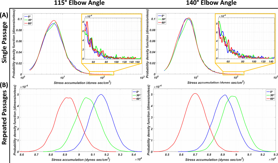
The main modes of the 115° HA5 elbow angle inflow cannula PDF located at the similar SA range despite the circumferential orientation differences with the highest probability found in the 60° orientation, followed by the 30° and the 0°; on the other hand, 0° had the highest probability between the SA range of 10–30 dyne·s/cm2. Additionally, the shortest tail region PDF (SA > 50 dyne·s/cm2) was found with the 0° circumferential orientation out of the three orientations (Figure 4-A). Similar PDF main mode distributions and tail lengths were found in the 140° elbow angle inflow cannula PDF- the 60° main mode had slightly wider distribution toward the lower SA and the 30° main mode was slightly skewed to the right (Figure 4-A). The HA5 repeated passages PDFs revealed that for the 115° elbow angle, the 0° circumferential orientation had the highest TP followed in descending order by the 30° and the 60°; for the 140° elbow angle, the highest TP was generated by the 30° circumferential orientation, followed in descending order by the 0° then the 60° (Figure 4-B). The statistics, e.g., mean SA value and the percentage of platelet population which were exposed to the higher SA range (i.e., above 50 dyne·s/cm2) of both single and repeated passages studies are presented in Table 1.
Figure 4.
PDF results of the HA5 VAD assembled to the inflow cannulae with 115° and 140° elbow angles, combined with three circumferential orientations of 0° (blue), 30° (green) and 60° (red). (A) Single passage: with the 115° inflow cannula, the 60° main mode has the highest probability, and the 0° has the highest probability within the SA range of 10–30 dyne·s/cm2 (inset- zoom in of the highest SA range at the PDF tail). With the 140° inflow cannula, the 60° main mode has slightly wider distribution toward the lower SA range. (B) Repeated passages PDFs: inflow cannula combined with 60° circumferential orientation generated the lowest thrombogenic potential (TP)- independent of its elbow angle. The highest TP was found with the 0° and 30° circumferential orientations combined with the 115° and 140° elbow angle cannulae, respectively.
Table 1.
Statistics of HA5 and HMII results
| Circumferential Orientation | 0° | 30° | 60° | ||
|---|---|---|---|---|---|
| HA5 | 115° | Single Passage Mean ± SD (dyne·sec/cm2) |
11.359 ± 8.88 | 11.239 ± 9.56 | 11.063 ± 9.21 |
| Percentage (%) of SA > 50 dyne·sec/cm2 |
0.63 | 0.86 | 0.79 | ||
| Repeated Passage Mean ± SD (dyne·sec/cm2) |
91595.3 ± 798.57 | 90627.51 ± 860.95 | 89208.29 ± 827.34 | ||
| 140° | Single Passage Mean ± SD (dyne·sec/cm2) |
11.053 ± 9.05 | 11.129 ± 9.01 | 10.791 ± 8.73 | |
| Percentage (%) of SA > 50 dyne·sec/cm2 |
0.79 | 0.82 | 0.68 | ||
| Repeated Passage Mean ± SD (dyne·sec/cm2) |
89134.12 ± 814.34 | 89742.97 ± 813.11 | 87020.95 ± 781.32 | ||
| HMII | Single Passage Mean ± SD (dyne·sec/cm2) |
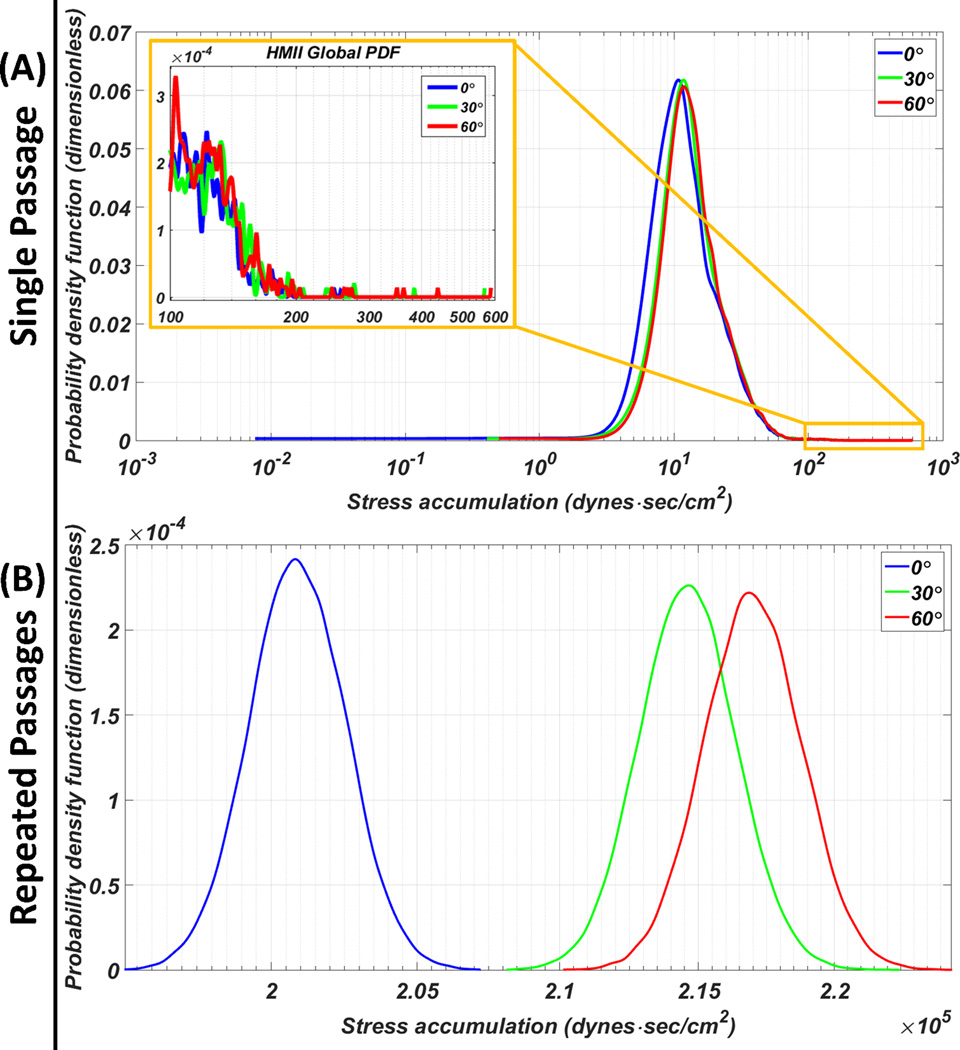
19.9324 ± 16.31 | 21.2926 ± 17.48 | 21.5285 ± 17.96 | |
| Percentage (%) of SA > 50 dyne·sec/cm2 |
3.76 | 4.3 | 4.41 | ||
| Repeated Passage Mean ± SD (dyne·sec/cm2) |
200918.4± 1623.92 | 214629± 1754.61 | 217006.9± 1809.34 | ||
single and repeated passages SAs, percentage of platelets exposed to SA beyond 50 dyne·sec/cm2;
SD: standard deviation
The HMII PDFs indicated that the left-shifted of the 0° main mode toward the lower SA range as compared to the other orientations; shorter tail was found at the 0° orientation tail region PDF (Figure 5-A; inset). The HMII repeated passages results revealed that the 0° circumferential orientation generated the highest TP followed in descending order by the 30° then 60° (Figure 5-B). The statistics of both single and repeated passages HMII results are presented in Table 1.
Figure 5.
PDF of the HMII VAD assembled to the inflow cannula at various circumferential orientations. (A) Single passage: 0° circumferential orientation generated the lowest SA main mode and the shortest high SA tail region (inset). (B) Repeated passages: significantly lower thrombogenic potential for the 0° circumferential orientation compared to the 30° and 60° orientations.
Outflow Cannulation
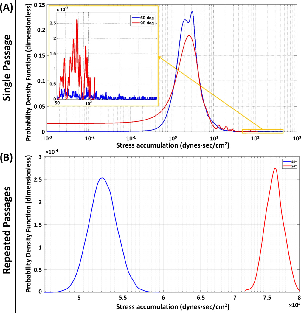
The PDF results of the 60° and 90° end-to-side anastomotic angles revealed that bimodal and unimodal distributions were observed in the 60° and 90° PDFs, respectively. The tail regions PDFs revealed that the longer tail of the 60° PDF; on the other hand, a secondary mode was observed in the 90° PDF (Figure 6-A, inset). The repeated passages results revealed two very distinct normally distributed PDFs for the two anastomotic angles (Figure 6-B). The statistics for both single and repeated passages results of the anastomotic angle studies are presented in Table 2.
Figure 6.
Effect of the anastomotic angles: (A) Single passage and (B) repeated passages PDF results for 60° (blue) and 90° (red). (A) The main modes for both anastomotic angles populated similar SA ranges, with a secondary mode observed in the tail region of the 90° (inset). (B) For the repeated passages significantly lower TP was observed for the 60°.
Table 2.
Statistic of different anastomotic angles
| Anastomotic Angles | 60° | 90° |
|---|---|---|
| Single Passage Mean ± SD (dyne·sec/cm2) | 6.5381 ± 17.36 | 9.4542 ± 16.85 |
| Percentage (%) of SA > 50 dyne·sec/cm2 | 1.18 | 4.39 |
| Repeated Passage Mean ± SD (dyne·sec/cm2) | 52722.91 ± 1551.64 | 76238.59 ± 1526.56 |
single and repeated passages SAs, percentage of platelets exposed to SA beyond 50 dyne·sec/cm2;
SD: standard deviation
Discussion
The pharmacological management of device-associated antithrombotic therapies remains challenging. While prior work demonstrated the efficacy of VAD design optimization methodology for reducing the overall thrombogenicity of the device itself,24–27 surgical implantation and patient anatomic variability has led to the consideration of analysis of other “VAD system” components as contributors to the overall MCS thrombogenicity. In order to account for these system effects, the present study modeled and quantified for the first time the thrombogenic footprint of each implantation configuration for a range of inflow and outflow geometric factors. Our results clearly demonstrated that the variation of these parameters impacts the TP of the implanted device, with each having a significant potential impact on overall MCS thrombogenicity, while indicating which implantation configurations and/or design factors exterior to the device itself are desirable as to achieve optimal performance of the implanted device.
The single and repeated passages models employed in the present studies provided the detail device thrombogenic footprint of the platelets flowing through the device and the long term system TP for an average life span of platelets.38 Such approaches facilitated simulating a closer to reality physiologic scenario. Due to the randomization of the trajectories during each successive passage and the resulting cumulative effect of these repeated passages, the repeated passage PDFs are characterized by closer to a normal statistical distribution and more distinct differences than those of the single passage PDFs.
The HA5 results indicated the 140° inflow cannula, which is designed for the smaller adults or pediatric patients, is a favorable configuration for the patients whose anatomical geometries are suitable, as lower TP was generated. Beside the options of the inflow cannula elbow angle, the HA5 inflow cannula is optimally attached to the pump with 60° circumferential orientation due to the lowest TP this configuration generated. On the other hand, the HMII results suggested that the HMII inflow cannula is best connected to the pump with 0° circumferential orientation, due to the significantly lower TP this orientation generated. These results indicated that the optimal configuration of how the pump should be configured with respect to the inflow cannula is device dependent, despite the fact that similar design concepts may be shared.
The outflow graft anastomosis result indicated that the risk of post-implant thromboembolic complications may be reduced by connecting the outflow graft to the ascending aorta with a 60° anastomotic angle. Such result coincides with the previous studies which showed that different anastomotic angles significantly affect the aortic flow pattern.39 In addition, the present study not only considered the outflow graft anastomotic angle, but also the aortic root swirling flow induced by the last phase of ventricular contraction, thus providing a more physiologically realistic result of modeling the post-implant system thrombogenicity.
As mentioned earlier, no specific instructions presently exist for surgeons with regard to detailed orientation and angulation guidelines for device and cannula implantation to optimize VAD performance and reduce thrombogenic risk. The present studies suggested that in order to optimize both the acute surgical and long-term medical outcome of VAD therapy, proper implantation configuration is needed to reduce the risk of post-implant thromboembolic complications.
The present studies bear certain limitations. The pump inflow conditions are affected by the ventricular contraction clinically which generates dynamic intraventricular pressure. In the present study, constant flow rates were employed to model the scenario that the device recipient is close to end-stage congestive heart failure, in which the aortic valve opening is marginal. The accuracy of transient simulations is affected by several factors, including the mesh size, platelet particle densities, time step sizes, and the simulation duration. The mesh size, particle densities and time step sizes were carefully determined according to the mesh independence studies, the physiological platelet count and the corresponding impeller speeds, respectively. If a full cardiac cycle waveform had been employed, the length of the simulations would be extended to a degree that the simulations may become computationally prohibitive. Given the large size of our computational meshes needed for these FSI simulations, the aortic wall was modeled as rigid, simplifying the compliance of the aortic wall that enables the vessel to radially distend and recoil through the cardiac cycle. Despite the non-Newtonian property of human blood, the present study utilized Newtonian fluid to reduce the simulation complexity as the present two-phase simulations are already computationally demanding; besides, the efficacy of such approach in high shear environment was successfully demonstrated in the previous studies.24,25,29,33 Lastly, platelets are continuously exposed to dynamic shear stresses while flowing in the circulation; however, the present studies calculated the stress exposure accumulated only while flowing through the implanted devices throughout the lifespan of platelets. While these values may underestimate the overall activity level of the platelets, it is clear that the platelets passages through the device are the dominant factor affecting the overall systemic thrombogenicity.
Conclusion
VAD thrombosis persists despite pump design optimization and anti-thrombotic therapy. Herein we demonstrated that VADs must be considered as part of a system of mechanical circulatory support – with inflow and outflow cannula geometries and orientation as system elements. Various geometric features related to either device design or the surgical implantation configuration, e.g., the inflow cannula angle, inflow cannula orientation and outflow cannula anastomotic angle, are additional variables that must be added to flow simulations to evaluate overall device and system post-implantation performance. Besides, significant differences in the TP may result if the system configuration is far from optimal, which may offset any thrombogenicity reduction achieved by device optimization per se. Insights gained from this study may have direct clinical applicability to alter and optimize surgical implantation techniques, thereby enhancing the safety and efficacy of the implanted VAD.
Acknowledgments
This was funded by NIH NIBIB Quantum Award Implementation Phase II, 1U01EB012487-0, DB.
Footnotes
Disclosure Statement:
None of the authors have a conflict of interest to declare.
This paper is not under consideration elsewhere.
None of the paper’s contents have been previously published.
All authors have read and approved the manuscript.
References
- 1.Mozaffarian D, Benjamin EJ, Go AS. Heart disease and stroke statistics-2015 update: a report from the American Heart Association. Circulation. 2015;131:e29–e322. doi: 10.1161/CIR.0000000000000152. [DOI] [PubMed] [Google Scholar]
- 2.Yancy CW, Jessup M, Bozkurt B. 2013 ACCF/AHA guideline for the management of heart failure: executive summary: a report of the American College of Cardiology Foundation/American Heart Association Task Force on practice guidelines. Circulation. 2013;128:1810–1852. doi: 10.1161/CIR.0b013e31829e8807. [DOI] [PubMed] [Google Scholar]
- 3.Loebe M, Bruckner B, Reardon MJ. Initial clinical experience of total cardiac replacement with dual HeartMate-II axial flow pumps for severe biventricular heart failure. Methodist Debakey Cardiovasc J. 2011;7:40–44. doi: 10.14797/mdcj-7-1-40. [DOI] [PubMed] [Google Scholar]
- 4.Netuka I, Maly J, Szarszoi O, Kautznerova D, Urban M, Pirk J. Novel treatment of an infiltrating cardiac fibrosarcoma. Tex Heart Inst J. 2014;41:248–249. doi: 10.14503/THIJ-13-3402. [DOI] [PMC free article] [PubMed] [Google Scholar]
- 5.Feng J, Cohn WE, Parnis SM. New continuous-flow total artificial heart and vascular permeability. J Surg Res. 2015;199:296–305. doi: 10.1016/j.jss.2015.06.035. [DOI] [PMC free article] [PubMed] [Google Scholar]
- 6.Frazier OH, Cohn WE. Continuous-flow total heart replacement device implanted in a 55-year-old man with end-stage heart failure and severe amyloidosis. Tex Heart Inst J. 2012;39:542–546. [PMC free article] [PubMed] [Google Scholar]
- 7.Stein ML, Yeh J, Reinhartz O. HeartWare HVAD for biventricular support in children and adolescents: The Stanford Experience. ASAIO J. 2016 doi: 10.1097/MAT.0000000000000356. [DOI] [PubMed] [Google Scholar]
- 8.Harvey L, Holley C, Roy SS. Stroke After Left Ventricular Assist Device Implantation: Outcomes in the Continuous-Flow Era. Ann Thorac Surg. 2015;100:535–541. doi: 10.1016/j.athoracsur.2015.02.094. [DOI] [PubMed] [Google Scholar]
- 9.Eckman PM, John R. Bleeding and thrombosis in patients with continuous-flow ventricular assist devices. Circulation. 2012;125:3038–3047. doi: 10.1161/CIRCULATIONAHA.111.040246. [DOI] [PubMed] [Google Scholar]
- 10.Morgan JA, Brewer RJ, Nemeh HW. Stroke while on long-term left ventricular assist device support: incidence, outcome, and predictors. ASAIO J. 2014;60:284–289. doi: 10.1097/MAT.0000000000000074. [DOI] [PubMed] [Google Scholar]
- 11.Kirklin JK, Naftel DC, Pagani FD. Seventh INTERMACS annual report: 15,000 patients and counting. J Heart Lung Transplant. 2015 doi: 10.1016/j.healun.2015.10.003. [DOI] [PubMed] [Google Scholar]
- 12.Nielsen VG, Kirklin JK, Holman WL. Mechanical circulatory device thrombosis: a new paradigm linking hypercoagulation and hypofibrinolysis. ASAIO J. 2008;54:351–358. doi: 10.1097/MAT.0b013e31817f3e03. [DOI] [PubMed] [Google Scholar]
- 13.Pieri M, Scandroglio AM, Kukucka M. Heart failure after 5 years on LVAD: diagnosis and treatment of out-flow graft obstruction. ASAIO J. 2016 doi: 10.1097/MAT.0000000000000370. [DOI] [PubMed] [Google Scholar]
- 14.Thoennissen NH, Schneider M, Allroggen A. High level of cerebral microembolization in patients supported with the DeBakey left ventricular assist device. J Thorac Cardiovasc Surg. 2005;130:1159–1166. doi: 10.1016/j.jtcvs.2005.02.068. [DOI] [PubMed] [Google Scholar]
- 15.Oezpeker C, Zittermann A, Ensminger S. Systemic Thrombolysis versus Device Exchange for Pump Thrombosis Management: A Single Center Experience. ASAIO J. 2016 doi: 10.1097/MAT.0000000000000340. [DOI] [PubMed] [Google Scholar]
- 16.Starling RC, Moazami N, Silvestry SC. Unexpected abrupt increase in left ventricular assist device thrombosis. N Engl J Med. 2014;370:33–40. doi: 10.1056/NEJMoa1313385. [DOI] [PubMed] [Google Scholar]
- 17.Mokadam NA, Andrus S, Ungerleider A. Thrombus formation in a HeartMate II. Eur J Cardiothorac Surg. 2011;39:414. doi: 10.1016/j.ejcts.2010.06.015. [DOI] [PubMed] [Google Scholar]
- 18.Meyer AL, Kuehn C, Weidemann J. Thrombus formation in a HeartMate II left ventricular assist device. J Thorac Cardiovasc Surg. 2008;135:203–204. doi: 10.1016/j.jtcvs.2007.08.048. [DOI] [PubMed] [Google Scholar]
- 19.Unai S, Hirose H, Entwistle JW, 3rd, Samuels LE. Resolution of hemolysis from pump thrombus during left ventricular assist device exchange. World J Clin Cases. 2014;2:373–376. doi: 10.12998/wjcc.v2.i8.373. [DOI] [PMC free article] [PubMed] [Google Scholar]
- 20.Baumann Kreuziger LM, Kim B, Wieselthaler GM. Antithrombotic therapy for left ventricular assist devices in adults: a systematic review. J Thromb Haemost. 2015;13:946–955. doi: 10.1111/jth.12948. [DOI] [PubMed] [Google Scholar]
- 21.Kantorovich A, Fink JM, Militello MA, Bauer SR, Soltesz EG, Moazami N. Comparison of Anticoagulation Strategies After Left Ventricular Assist Device Implantation. ASAIO J. 2016;62:123–127. doi: 10.1097/MAT.0000000000000317. [DOI] [PubMed] [Google Scholar]
- 22.Sheriff J, Girdhar G, Chiu WC, Jesty J, Slepian MJ, Bluestein D. Comparative efficacy of in vitro and in vivo metabolized aspirin in the DeBakey ventricular assist device. J Thromb Thrombolysis. 2014;37:499–506. doi: 10.1007/s11239-013-0997-6. [DOI] [PMC free article] [PubMed] [Google Scholar]
- 23.Valerio L, Tran PL, Sheriff J. Aspirin has limited ability to modulate shear-mediated platelet activation associated with elevated shear stress of ventricular assist devices. Thromb Res. 2016;140:110–117. doi: 10.1016/j.thromres.2016.01.026. [DOI] [PMC free article] [PubMed] [Google Scholar]
- 24.Chiu WC, Girdhar G, Xenos M. Thromboresistance comparison of the HeartMate II ventricular assist device with the device thrombogenicity emulation- optimized HeartAssist 5 VAD. J Biomech Eng. 2014;136:021014. doi: 10.1115/1.4026254. [DOI] [PMC free article] [PubMed] [Google Scholar]
- 25.Girdhar G, Xenos M, Alemu Y. Device thrombogenicity emulation: a novel method for optimizing mechanical circulatory support device thromboresistance. PLoS One. 2012;7:e32463. doi: 10.1371/journal.pone.0032463. [DOI] [PMC free article] [PubMed] [Google Scholar]
- 26.Frazier OH, Khalil HA, Benkowski RJ, Cohn WE. Optimization of axial-pump pressure sensitivity for a continuous-flow total artificial heart. J Heart Lung Transplant. 2010;29:687–691. doi: 10.1016/j.healun.2009.12.017. [DOI] [PubMed] [Google Scholar]
- 27.Toptop K, Kadipasaoglu KA. Design and numeric evaluation of a novel axial-flow left ventricular assist device. ASAIO J. 2013;59:230–239. doi: 10.1097/MAT.0b013e31828a6bc1. [DOI] [PubMed] [Google Scholar]
- 28.Xenos M, Girdhar G, Alemu Y. Device Thrombogenicity Emulator (DTE)--design optimization methodology for cardiovascular devices: a study in two bileaflet MHV designs. J Biomech. 2010;43:2400–2409. doi: 10.1016/j.jbiomech.2010.04.020. [DOI] [PMC free article] [PubMed] [Google Scholar]
- 29.Dimasi A, Rasponi M, Sheriff J. Microfluidic emulation of mechanical circulatory support device shear-mediated platelet activation. Biomed Microdevices. 2015;17:117. doi: 10.1007/s10544-015-0015-1. [DOI] [PMC free article] [PubMed] [Google Scholar]
- 30.Taghavi S, Ward C, Jayarajan SN, Gaughan J, Wilson LM, Mangi AA. Surgical technique influences HeartMate II left ventricular assist device thrombosis. Ann Thorac Surg. 2013;96:1259–1265. doi: 10.1016/j.athoracsur.2013.05.081. [DOI] [PubMed] [Google Scholar]
- 31.MicroMed Cardiovascular Inc. http://reliantheart.com/wp-content/uploads/2013/04/FastConnect-4.jpg. [Google Scholar]
- 32.John R, Kamdar F, Liao K. Low thromboembolic risk for patients with the Heartmate II left ventricular assist device. J Thorac Cardiovasc Surg. 2008;136:1318–1323. doi: 10.1016/j.jtcvs.2007.12.077. [DOI] [PubMed] [Google Scholar]
- 33.Chiu WC, Slepian MJ, Bluestein D. Thrombus formation patterns in the HeartMate II ventricular assist device: clinical observations can be predicted by numerical simulations. ASAIO J. 2014;60:237–240. doi: 10.1097/MAT.0000000000000034. [DOI] [PMC free article] [PubMed] [Google Scholar]
- 34.Xenos M, Karakitsos D, Labropoulos N, Tassiopoulos A, Bilfinger TV, Bluestein D. Comparative study of flow in right-sided and left-sided aortas: numerical simulations in patient-based models. Comput Methods Biomech Biomed Engin. 2013 doi: 10.1080/10255842.2013.805210. [DOI] [PubMed] [Google Scholar]
- 35.Yushkevich PA, Piven J, Hazlett HC. User-guided 3D active contour segmentation of anatomical structures: significantly improved efficiency and reliability. Neuroimage. 2006;31:1116–1128. doi: 10.1016/j.neuroimage.2006.01.015. [DOI] [PubMed] [Google Scholar]
- 36.Stalder AF, Russe MF, Frydrychowicz A, Bock J, Hennig J, Markl M. Quantitative 2D and 3D phase contrast MRI: optimized analysis of blood flow and vessel wall parameters. Magn Reson Med. 2008;60:1218–1231. doi: 10.1002/mrm.21778. [DOI] [PubMed] [Google Scholar]
- 37.Kilner PJ, Yang GZ, Mohiaddin RH, Firmin DN, Longmore DB. Helical and retrograde secondary flow patterns in the aortic arch studied by three-directional magnetic resonance velocity mapping. Circulation. 1993;88:2235–2247. doi: 10.1161/01.cir.88.5.2235. [DOI] [PubMed] [Google Scholar]
- 38.Dumont K, Vierendeels J, Kaminsky R, van Nooten G, Verdonck P, Bluestein D. Comparison of the hemodynamic and thrombogenic performance of two bileaflet mechanical heart valves using a CFD/FSI model. J Biomech Eng. 2007;129:558–565. doi: 10.1115/1.2746378. [DOI] [PubMed] [Google Scholar]
- 39.May-Newman KD, Hillen BK, Sironda CS, Dembitsky W. Effect of LVAD outflow conduit insertion angle on flow through the native aorta. J Med Eng Technol. 2004;28:105–109. doi: 10.1080/0309190042000193865. [DOI] [PubMed] [Google Scholar]


