Abstract
High-resolution peripheral computed tomography is commonly used to evaluate mechanical behavior of the distal radius microstructure using micro-finite element (FE) modeling. However, only a 9 mm section is considered and boundary conditions (BCs) are usually simplified (platen compression), and may not represent physiologic loading. Regardless, these methods are increasingly being used for clinical evaluations. Our goal was to develop and validate a novel multiscale solution that allows for physiologically relevant loading simulations (such as bracing during a fall), and show that mechanical behavior in the distal radius is different under platen BCs. Our approach incorporated bone microstructure together with organ-level radius geometry, by replacing matching continuum regions with micro-FE sections in user-defined regions of interest. Multiscale model predicted strains showed a strong correlation and a significant relationship with measured strains (r = 0.836, p < 0.001; slope = 0.881, intercept = −12.17 με, p < 0.001). Interestingly, platen BC simulated strains were almost 50% lower than measured strains (r = 0.835, p < 0.001), and strain distributions were clearly different. Our multiscale method demonstrated excellent potential as a computationally efficient alternative for observing true mechanical environment within distal radius microstructure under physiologically accurate loading.
Keywords: High-resolution peripheral computed tomography, microstructure, multiscale, micro-finite element, continuum finite element
1. Introduction
Computed tomography (CT) and finite element (FE) analysis are established tools used to investigate mechanical behavior at the distal radius under various conditions. Typically, the FE analyses involve organ- (macro) level bone geometry acquired from CT images at clinical-resolution (voxel size 234×234×625 μm or greater), to determine in situ strains [1–3], fracture strength [4–6], and the efficacy of fracture fixation methods [7–9]. The relatively lower resolution of the CT images provides insufficient structural detail through the cross-section. To account for this limitation, the FE analyses are restricted to a continuum assumption with inhomogeneous material properties related to density distribution, derived from voxel intensities of the images [10–12]. Depending on the application, distal radius continuum FE models provide useful information on cortical strains and integral whole bone mechanics. Bone however, is a complex structure consisting of cortical (low porosity) and trabecular (highly porous) regions each playing a unique role in whole-bone mechanics [13, 14]. The microstructure of the trabecular region is particularly important to take into consideration because of its increased susceptibility to bone loss and osteoporosis [15, 16], and its age-related changes in anisotropy [17].
High-resolution peripheral quantitative CT (HR-pQCT) is able to resolve bone microstructure (82×82×82 μm voxel size), making the non-invasive evaluation of cortical and trabecular microstructure at the human distal radius possible [18, 19]. Due to the significantly longer scan times (∼20 times > clinical CT), standard HR-pQCT protocols only consider a volume of interest typically 9.0 mm in length (110 transverse slices). This scan length sufficiently captures the clinically relevant region of the distal radius where fractures typically occur. HR-pQCT has been applied to study age-related changes, effects of diseases, and outcomes of various treatments on bone microstructure [20–24]. Also, HR-pQCT data are used to generate micro-FE models incorporating microstructure to evaluate distal radius mechanical behavior [25–30]. From the images, voxels of the cortical and trabecular bone regions are directly converted to an FE mesh and assigned homogeneous material properties. However, the micro-FE analyses only model the 9.0 mm thick section of the distal radius and the boundary conditions (BCs) usually simulate a simplified uniaxial compression test between two platens. Essentially, the proximal surface of the bone section is fixed and a uniform axial displacement (or load) is applied to the distal surface [31]. Though these simulations do not represent physiologic conditions, measures from these analyses are increasingly being used as outcomes for clinical trials [22, 23, 32, 33]. While simplified platen BCs may only result in a systematic variation in parameters compared to physiologic BCs, the effect of these BCs on estimated bone mechanical behavior has not been determined. Furthermore, physiologically relevant BCs are important to understand true mechanical environment within bone, which is associated with structural adaptation [34].
Ideally, FE simulations of the radius would involve micro-FE meshes of the organ-level geometry (incorporating microstructure), non-linear inhomogeneous material properties, simulated under physiologic BCs (such as axial loading through the extended wrist corresponding to most activities of daily living). However, due to time, current computational constraints, and impracticalities associated with acquiring large volumes of HR-pQCT data, these analyses are not possible using data from living human subjects. To address these limitations, a “compromise” approach would involve a micro-macro-level multiscale analysis where only select regions of interest within organ-level geometry (continuum-FE) incorporate microstructure (micro-FE).
Hence, the goals of this study were twofold. 1) To develop and validate a novel multiscale approach to solve continuum and micro-FE models simultaneously under physiologic boundary conditions. Strain was chosen as an outcome for validation because it is an important mechanical stimulus associated with bone adaptation [35, 36]. 2) To compare results of distal radius micro-FE loading simulations performed using physiologic BCs (multiscale models) and simplified platen BCs, versus experimental results. We hypothesized that platen BC simulations would exhibit different mechanical behavior at the distal radius region compared to physiologic BC simulations.
2. Methods
2.1. Specimens
Data were acquired from 10 fresh-frozen cadaveric left forearms with the hand intact (4 males, 6 females; mean age 64 years, range 32–89). The specimens were thawed to room temperature for image acquisition, experimental setup and mechanical testing. While thawed, the specimens were kept moist using a saline solution.
2.2. Image Acquisition
All images were acquired using an XtremeCT HR-pQCT scanner (Scanco Medical, Switzerland). Two sets of images were acquired per specimen; clinical-resolution images of a 11 cm region of the distal forearm and wrist in 60° extension (246×246×246 μm voxel size, 126 mm field of view, 60 kV, 0.9 mA), and high-resolution images of a 9.0 mm region of the distal radius (82×82×82 μm voxel size, 126 mm field of view, 60 kV, 0.9 mA). The high-resolution image region corresponded to the strain gage attachment sites (distal set; see Section 2.3). All CT images were calibrated using a phantom with known calcium hydroxyapatite (HA) equivalent concentrations provided by the manufacturer.
2.3. Specimen Preparation and Mechanical Testing
All soft tissue was dissected off the forearm proximal to the wrist joint capsule, leaving the interosseous membrane intact (Fig. 1). A transverse osteotomy was performed 14 cm proximal to the Lister’s tubercle, and the proximal most 7 cm of bone was potted in polyurethane (7 cm exposed). For strain gage attachment, the periosteum was removed and the bone surface was sanded and cleaned with isopropyl alcohol. Three stacked rosettes (C2A-06-031WW-120, Micro-Measurements, Raleigh, NC) were attached circumferentially (anterior, posterior-lateral, posterior-medial) at the distal radius proximal to the Lister’s tubercle (Fig. 1B, C). Three additional gages were attached 3 cm proximal to the distal gages in a similar configuration. The location of the distal gages (predominantly trabecular region) was in the vicinity of the clinically relevant site for distal radius fractures, and the proximal gages (predominantly cortical region) provided a greater range of strain measurement. The gages were attached using cyanoacrylate glue and coated with polyurethane.
Figure 1.
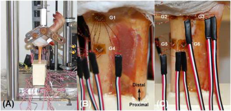
Medial view of the mechanical testing setup showing the wrist positioned in 60° extension using a custom fixture (A). Anterior (B) and posterior (C) views of the dissected forearm showing the locations of the distal (G1, G2, G3) and proximal (G4, G5, G6) stain gage rosettes.
The experimental setup replicated a fall configuration (Fig. 1A). The wrists were fixed in 60° extension (relative to forearm long axis) using a custom fixture and the potted ends were unconstrained to minimize frictional shear. The specimens were loaded in compression to 300 N at a rate of 0.1 mm/s using a uniaxial materials testing machine (ElectroPuls E1000, Instron, Norwood, MA). The target force of 300 N was chosen on the basis of achieving a range of periosteal strain magnitudes associated with structural adaptation (1000–2000 με), extrapolated from animal models [37, 38]. Force, displacement and strain data were collected simultaneously at 80 Hz. Only 14 analog channels were available for data acquisition, therefore, data were collected from 4 gages per trial (3 channels per gage: 4×3=12 channels; plus 2 channels for force, displacement). A total of 10 trials were performed, allowing for 5 repeat trails per gage (approximately three minute loading intervals), with data from two gages acquired throughout to assess for variability.
2.4. Modeling
Figure 2 summarizes the workflow of the modeling procedures involving continuum only models (to determine contact BCs for the multiscale analyses), multiscale models (continuum+mico-FE), and micro-FE only models (for comparison of BCs).
Figure 2.
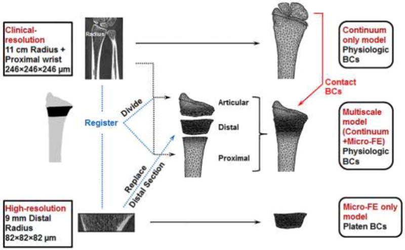
Summary of the workflow of the modeling procedures for each specimen involving a continuum only model, multiscale model (continuum+mico-FE), and micro-FE only model generated from the low- and high-resolution images.
Continuum Only Model Analyses
For time and computational efficiency, cartilage contact BCs for the multiscale model analyses were determined from the corresponding continuum only model analyses. The procedures for creating the continuum models were based on prior validated methods, which were shown to have a root mean squared coefficient of variation of 0.3% for strain measures [1]. Briefly, to acquire model geometries the radius, scaphoid and lunate bones were segmented from the clinical-resolution images in Mimics (Materialise, Leuven, Belgium) using a fixed minimum cortical density threshold (ρHA = 0.210 g/cm3) for all specimens. The scaphoid and lunate were included in the models for physiologically accurate forearm loading (Fig. 3). Cartilage was created by expanding the articular radius surface to be in contact with the scaphoid and lunate (∼1.4 mm cartilage thickness). The bone and cartilage geometries were meshed in 3-matic (Materialise, Leuven, Belgium) using 10-node tetrahedral elements [113, 228 ± 26, 021 nodes; 302, 725 ± 71, 671 degrees of freedom (mean ± SD)], with acceptable edge lengths determined from a convergence analysis (2 mm and 3 mm for cartilage and bone, respectively). The cartilage was modeled as a hyperelastic neo-Hookean deformable solid (E = 10 MPa, ν = 0.45) [39], and the scaphoid and lunate were modeled as rigid non-deformable solids. Linear elastic, isotropic (ν = 0.4), inhomogeneous material properties were assigned to the radius based on an established density-elasticity relationship [12]. CT Houndsfield units were converted to ρHA using the CT phantom calibration and linearly incremented into 200 bins. Elements were assigned a modulus value corresponding to the average ρHA in each bin (no change in outcome with > 200 elements based on a sensitivity analysis). To account for negative modulus values due to the presence of marrow fat, ρHA values < 0.01 g/cm3 were assigned ρHA = 0.01 g/cm3. To account for lower modulus values at the periosteal surface due to partial volume effects, material assignment was based on ρHA values restricted to 1 voxel within the segmented radius area. Elements outside this area (< 0.3%) were assigned an average ρHA of the perimeter voxels of the restricted area.
Figure 3.
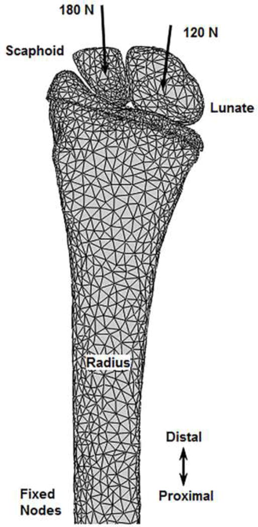
Anterior view of an example continuum only finite element model setup. Axially-directed loads were applied through the carpal centroids with the proximal radius fixed, replicating the boundary conditions of the experiment.
FE analyses were performed using Abaqus 6.12 (Simulia, Providence, RI). A finite sliding formulation was used to model normal contact interaction between the bone and cartilage surfaces and a penalty method was used to model tangential behavior. An augmented Lagrange method was used to enforce the pressure-overclosure relationship. Once in contact, carpal bone rotation and sliding were constrained to account for the wrist ligamentous and capsular physiological constraints. To replicate the experimental setup, a 300 N ramped quasi-static load was applied axially through the centroids of the scaphoid and lunate bones (oriented in 60° wrist extension during CT scanning), towards the proximal radius. Using proximal strain gage and CT data, load direction was determined using unsymmetrical beam theory [3]. Based on percentage of load transfer through the radiocarpal joint, 180 N and 120 N were applied through the scaphoid and lunate, respectively [40, 41]. The proximal radius nodes were fixed similar to the location of potting. For two specimens, due to above average size and CT gantry limitations, the scan length included an insufficient region of the radius to fix the proximal nodes at the potting location. Consequently, the proximal most 0.5 cm region of the nodes was fixed, which was appropriately distant from the proximal gage locations so as not to affect outcome (Saint-Venant’s principle). Contact normal forces and shear forces were determined on the nodes of the cartilage surface to apply as BCs for the multiscale model analyses.
Multiscale Model Analyses (Physiologic BCs)
Figure 4 shows an example model setup for the multiscale analyses. The setup consisted of three sections (Fig. 4A); a continuum articular section, a micro-FE distal section, and a continuum proximal section.
Figure 4.
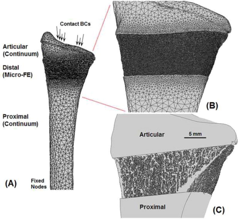
Anterior view of an example multiscale model setup (A) comprising three sections; a continuum articular section, a micro-FE distal section, and a continuum proximal section. Enlarged view showing microstructure details on the surface (B) and through the cross-section (C). Due to partial volume effects in the clinical-resolution images, small edge differences can occur between continuum and micro-FE sections.
The clinical-resolution segmented (“full”) radius was divided into articular and proximal sections using image registration. Image registration was performed using custom code (Matlab, Mathworks, Natick, MA) to align the 9.0 mm high-resolution distal radius region with the full clinical-resolution radius (Fig. 5). Cross-sectional area comparison was first used to automatically identify the clinical-resolution radius sub-region that matched the 9.0 mm high-resolution distal radius region. The 9.0 mm high-resolution distal radius region was then registered to the matching clinical-resolution radius sub-region using a mutual information method of maximizing relative pixel intensities. A laboratory sensitivity analysis using the International Society for Clinical Densitometry guidelines (minimum 30 degrees of freedom) showed high registration accuracy with rotation errors of 0.47 ± 0.38°, 0.46 ± 0.41° and 0.32 ± 0.24° in the x, y and z directions, respectively. Using the transformation from image registration, the full clinical-resolution radius was divided into articular and proximal sections (Figs. 2, 4), which were converted into continuum meshes as previously described.
Figure 5.
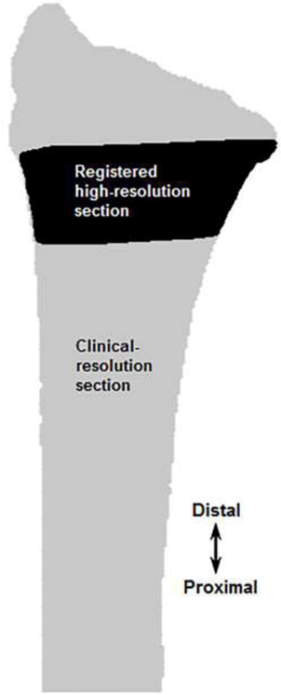
Image registration used to align the 9.0 mm high-resolution distal radius region with the full clinical-resolution radius to create sections for the multiscale models.
To acquire micro-FE model geometries, cortical and trabecular bone were segmented from the high-resolution images of the 9.0 mm distal radius region using the manufacturer’s standard protocols [42]. The bone voxels were directly converted into a micro-FE voxel mesh of 8-node hexahedral elements, with linear elastic, homogeneous material properties (E = 15 GPa, ν = 0.4 [25, 43]). This element type allows for automatic mesh generation from high-resolution CT datasets, significantly reducing user and computational effort, while also allowing for a high quality and numerically stable FE mesh (better aspect ratio/Jacobian). Furthermore, this allows for comparison of results across micro-FE studies of the distal radius that mostly incorporate voxel elements [25– 30]. The spatial transformation obtained during image registration was also used to position the micro-FE distal section between the articular and proximal clinical-resolution continuum sections (Figs. 2, 4). The multiscale models consisted of 3, 439, 797 ± 804, 058 nodes and 10, 319, 392 ± 2, 412, 175 degrees of freedom.
Multiscale model FE analyses were also performed using Abaqus. To ensure nodal continuity between the three sections, the micro-FE section nodes at the interfaces were coupled to the continuum sections using a tied constraint. This constrained the nodes of the micro-FE section to have the same translational and rotational degrees of freedom as the nodes of the continuum sections to which they were tied. A surface-based formulation was used to minimize numerical noise, where the constraints were enforced by averaging over a finite region (instead of discrete points). Position tolerance was used to couple nodes only from micro-FE elements one voxel adjacent to the interfaces. To improve connectivity between nodes of the continuum (articular, proximal) and micro-FE (distal) sections, the continuum meshes were progressively refined at the section interfaces (Fig. 4B). The refinement was optimized to ensure maximal connectivity while keeping the model size reasonable. This resulted in a majority of the micro-FE nodes (∼99.6%) being coupled with the continuum sections. Cartilage surfaces for the multiscale model setup were the same as the corresponding continuum only model analysis setup. Contact BCs (normal and shear forces) from the continuum only model analyses were applied to the same cartilage nodes of the multiscale models. The proximal radius nodes were fixed similar to the location of potting. The simulations were performed on a UNIX server with 16–30 processors (2.2–2.9 GHz) and 40–140 GB RAM.
Micro-FE Only Model Analyses (Platen BCs)
The same micro-FE distal sections from the multiscale model analyses were also used to simulate platen BC analyses (Fig. 6). Analyses were performed using Abaqus. Nodes on the distal surface were kinematically coupled (all degrees of freedom constrained) to a reference node located at the centroid of the distal cross-section. A uniform 300 N force was applied to the reference node, while the nodes of the proximal surface were fixed.
Figure 6.
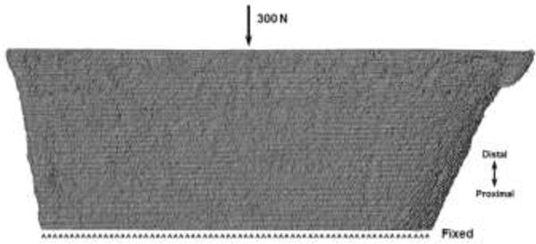
Anterior view of an example micro-FE only model setup simulating platen boundary conditions. The same total force as the physiologic boundary condition simulations was applied uniformly at the distal end, while the proximal end was fixed.
2.5. Outcome Measures and Statistical Analyses
Experimentally measured strain data from the rosettes were used to calculate maximum (εmax) and minimum (εmin) principal strains at the 300 N target load. Principal strains (εmax, εmin) predicted from the FE analyses were determined at the surface nodes enclosed within the plane of each proximal and distal gage. Nodal values were averaged at each gage location.
Between-trial reliability of the experiment principal strain data at 300 N was assessed using intra class correlations (ICC). Variability was then assessed using standard error of measurement [SEM = SD × (1 – ICC)1/2] [44]. Multiscale model predicted principal strains at 300 N were compared to experimental values using Pearson’s correlation and linear regression. A Bland-Altman plot was used to assess the agreement between the two measurements (experiment, multiscale model predicted principal strains), where the differences between the two measurements are plotted versus the means of the two measurements. Proportionality bias was then assessed by a linear regression analysis of the differences and means. Since the data from cadaver specimens were used to develop the multiscale model method and also for validation, a leave-one-out analysis was performed to assess the effect of within-specimen variability and whether the results could be generalized. Pearson’s correlations were determined for the remaining (n-1) specimen data when results from each specimen were left out consecutively, and the variation in Pearson’s r values were examined. Experimental principal strains, multiscale model predicted principal strains (physiologic BCs), and micro-FE only model predicted principal strains (platen BCs) at the distal gage locations, were compared using Pearson’s correlation and linear regression. Principal strain distribution was qualitatively compared between the physiologic and platen BC simulations. For all statistical analyses p < 0.05 was defined as significant.
3. Results
3.1. Experimentation
One specimen (female) was found to have had a recently healed radial styloid tip fracture; therefore, the data from this specimen were excluded from the analyses. Results are presented for the remaining 9 specimens. Also for two specimens, data from one trial produced erroneous results due to recording error; therefore, only data from the remaining 4 trials were analyzed. Experimental principal strain data were found to be highly reliable. ICCs for εmax and εmin between 5 trials were 0.955 and 0.956, respectively. The SEM for εmax was 22 με and for εmin was 35 με. This corresponded to 3.6% and 4.9% of the highest measured εmax (613 με) and εmin (−709 με) values, respectively.
3.2. Comparison between measured and multiscale model predicted (physiologic BCs) principal strains
A strong correlation was found between the measured and multiscale model predicted principal strains (r = 0.836, p < 0.001). Regression analysis (Fig. 7) indicated a significant relationship (slope = 0.881, intercept = −12.17 με, p < 0.001). Bland-Altman plot (Fig. 8) indicated a randomly distributed scatter without a proportionality bias (slope = −0.057, p = 0.328 [not different from zero]). Correlation coefficient values varied between 0.827 and 0.852 (all p < 0.001) based on the results of the leave-one-out analysis. Interestingly, multiscale model predicted principal strains were more strongly correlated to the measured strains from the distal gages (r = 0.87, p < 0.001 ; slope = 1.04, intercept = 1.71 με, p < 0.001) than the proximal gages (r = 0.812, p < 0.001; slope = 0.714, intercept = −29.08 με, p < 0.001) (Fig. 9).
Figure 7.
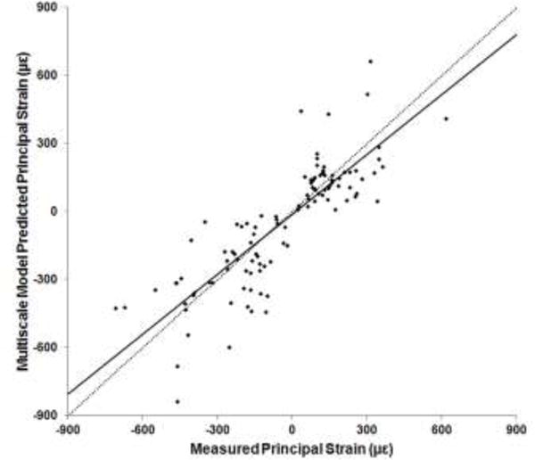
Plot of experimentally measured versus multiscale model predicted principal strains at 300 N. Dotted line indicates a y=x relationship.
Figure 8.
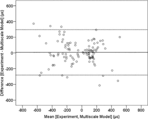
Bland-Altman plot with the solid line indicating the mean of the difference, and the dashed lines indicating the upper and lower limits of the 95% confidence interval.
Figure 9.
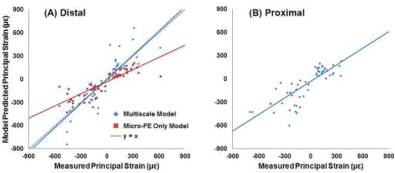
Plots of experimentally measured principal strains at the distal (A) and proximal (B) gage locations, versus model predicted principal strains. Physiologic (multiscale model) and platen boundary condition (micro-FE only model) simulation results were compared to the measured strains from the distal gages.
3.3. Comparison between measured, multiscale model predicted (physiologic BCs), and micro-FE only model predicted (platen BCs) principal strains
Principal strains from both simulations were significantly correlated to the measured strains (Fig. 9A), with the multiscale model predictions slightly better correlated than the micro-FE only model predictions (r = 0.87 and r = 0.835, respectively; p < 0.001). However, the slope of the regression line for the platen BC simulations was approximately 50% lower (slope = 0.522, p < 0.001 [different from unity]; intercept = −29.02 με, p = 0.02 [different from zero]) compared to the physiologic BC simulations (slope = 1.04, p = 0.628 [not different from unity]; intercept = 1.71 με, p = 0.935 [not different from zero]). Distribution of principal strains on the surface and through the cross-section was clearly different between the physiologic (multiscale model) and platen BC analyses (Fig. 10).
Figure 10.
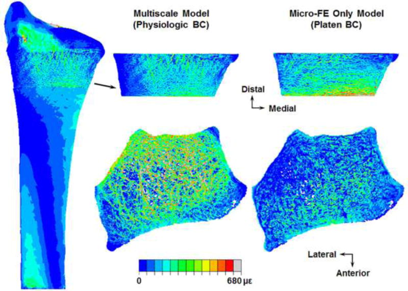
Distribution of maximum principal (tensile) strains on the surface (top row) and through the cross-section (bottom row) of an example micro-FE section simulated under physiologic (multiscale model) and platen boundary conditions (BC).
4. Discussion
Our goal was to implement a multiscale approach for the radius that allows for physiologically relevant boundary condition simulations of micro-FE sections generated from HR-pQCT images. Here we demonstrated the feasibility of our multiscale concept, which is to replace the matching region of the full clinical-resolution continuum radius with the micro-FE section incorporating microstructure. Trabecular anisotropy, which contributes to whole bone mechanics [45] can be taken into account during FE analyses by resolving microstructure (geometry, orientation) [46–48]. In theory, organ-level radius FE models would incorporate microstructure. In practice, this is not possible in vivo due to large volumes of data (storage, processing) and increased scan time, which increases the effective radiation dose and presence of motion artifacts. There is a need for multiscale models for more accurate predictions of bone mechanical behavior [6], and our methods represent a key step in implementing a true physiologically accurate multiscale approach, combining organ-level continuum models and micro-FE models for simultaneous analysis.
The capability of the multiscale models to accurately predict strains was demonstrated by the strong correlation with experimentally measured values, and the significant y=x linear relationship between model predicted and measured strains (Fig. 7). The absence of a systematic scatter on the Bland-Altman plot further illustrated a strong agreement between multiscale model predicted and measured strain magnitudes. Results of the leave-one-out analysis indicated that outcome was not affected by within-specimen variability and therefore can be generalized. For a 300 N applied load our strain results corresponded well with published data (r = 0.928, r = 0.90 [1, 3]). Micro-FE models better capture specimen-specific variations in bone geometry that are associated with mechanical behavior [49], which could partially explain the better correlation observed between the multiscale model predicted and measured strains at the distal versus the proximal gage locations (Fig. 9).
Interestingly, we observed an almost 50% systematic underestimation of strains predicted from the platen BC (micro-FE only model) simulations compared to the physiologic BC (multiscale model) and measured results (Fig. 9A). Current in vivo HR-pQCT generated micro-FE simulations of the radius are not necessarily representative of in vivo loading pathways. This can lead to altered mechanical behavior through a different mechanism of load transmission. For example, FE simulations with load applied directly to the isolated radius versus through the intact wrist resulted in over twice the predicted value of fracture strength [4]. Under platen BCs (though correlated), larger regions of the periosteal surface experienced higher strains for the same applied load (Fig. 10), possibly due to the cortex bearing the majority of the load resulting from higher stiffness of the cortical region. Physiologically, joint loads are transmitted through the trabecular region to the cortex [4]. The offset in platen BC predicted strains may indicate a discrepancy in whole bone strength indices, possibly an overestimation in stiffness. Future studies will quantify the differences between experimentally measured, multiscale model, and micro-FE only model predicted stiffness and fracture strength, which was beyond the current scope. Also, the orientation of the micro-FE section for platen BC simulations matched the orientation of the micro-FE distal section for physiologic BC simulations (aligned to the full radius), which could partly contribute to the significant correlation. It is possible to acquire HR-pQCT scans with the radius not axially aligned, in which case the platen BCs are not exactly transverse. Standard HR-pQCT protocols apply platen BCs directly to micro-FE sections generated from the images acquired at the scan orientation, which could further reduce the correlation.
Among other factors, the strain environment that bone experiences influences structural adaptation [34–36]. If physiologically relevant loading pathways indeed produce unique mechanical behavior, as our data indicate, it would be difficult to interpret results of studies investigating the effects of mechanical or pharmacologic interventions on bone quality, when the FE simulations are performed under platen BCs (for example; effect of drugs to improve bone strength and fracture healing after treatment for Colles’ fracture). Further disparity would arise in instances where the targeted intervention affects cortical and trabecular compartments differently (for example; parathyroid hormone increases trabecular bone mineral density but has a lesser effect on cortical bone [33]), since the mechanism of loading is predominantly cortical. The strong correlation with experimental results suggests that the strength of micro-FE platen BC analyses lies in prospectively monitoring changes in distal radius mechanical variables, because though the absolute value may not be physiologic, the offset is systematic. However, it would be difficult to correlate mechanical variations with localized structural changes (identifying an adaptation threshold) due to the lower strain magnitudes (Fig. 9A) and different strain distributions (Fig. 10). Studies applying platen BCs to distal radius micro-FE sections have reported stiffness values of approximately 100 kN/mm (linear analyses; adjusting for homogeneous modulus [22, 25, 26, 28–30, 32, 33]). If stiffness is indeed overestimated, then the ability of platen BC simulations to detect smaller differences in magnitude may also be diminished.
Some of the limitations of our study relate to potential sources of methodological error. 1) For computational efficiency cartilage contact BCs for the multiscale models were transferred from the corresponding continuum only model analyses (∼12× speedup). Since cartilage surfaces were the same and contact forces were applied to the same nodes, minimal error was expected. This step could potentially be redundant with future hardware advancements. 2) Constraining the micro-FE distal section to the continuum (articular, proximal) sections may have influenced nodal parameters at the interfaces. However, geometrical and numerical steps were undertaken to minimize this possibility. Furthermore, a sensitivity analysis of principal strains to distance from interfaces indicated < 1.8% change in average values one voxel (82 μm) from the interfaces, and < 0.2% change two voxels from the interfaces. 3) Due to partial volume effects in the clinical-resolution images small edge differences can occur, leading to surface discontinuities at the interface of the micro-FE and continuum proximal sections (Fig. 4C). This effect is specific to surface elements and could partially explain the lower correlation observed between the multiscale model predicted and measured proximal surface strains. The threshold used to define continuum bone geometry ensured that the micro-FE distal section was enclosed within the continuum sections. Also, the region of interest typically is the micro-FE distal section, which was highly correlated to experimental data. 4) Imperfect image registration between the two images sets could also have introduced error; however, registration sensitivity indicated accuracy to within 0.5°. 5) The relatively low number of specimens was also a limitation; however, the results provided satisfactory confidence in the robustness of the methods used to develop our approach.
Currently, FE models of bone either account for complex geometric/material behavior and simplify BCs, or incorporate complex BCs and simplify material behavior. Including additional detail does not always produce more accurate predictions due to increased assumptions, nor is it always computationally practical. Full radius HR-pQCT studies have mostly used cadaveric forearms, where either the entire radius geometry is converted into a micro-FE mesh [49] or micro-FE meshes of consecutive radius sections are analyzed [31, 50]. Also, HR-pQCT platen BC studies typically attempt to simulate the loading mechanism of Colles’ fracture. However, radius mechanics is highly sensitive to loading direction [5], and the pathway is a complex interaction of axial loads through the carpal bones and bending moments due to ligamentous constraints. Various methods have been developed to further facilitate FE simulations. These include continuum simulations incorporating anisotropy fabric tensor derived from HR-pQCT images for computational efficiency [43, 51], extrapolating radiocarpal joint loads from internal forces and moments estimated at the cross-section ends of the 9.0 mm section [52], or resolving physiologic BCs to the local sub-section level. Our multiscale approach does not require a priori force assumptions, and provides a practical solution to observe microstructure mechanical behavior at user-defined regions of interest under any physiologically relevant boundary condition, which is also computationally efficient. Using our current hardware the multiscale models required on average 32 hours to complete. As servers become more accessible (GPU computing), the time required to complete these analyses should exponentially decrease.
In conclusion, we have validated a novel multiscale modeling approach to evaluate mechanical behavior in the microstructure at the distal radius under physiologic boundary conditions. These methods can be applied to replace any matching distal region of the organ-level continuum radius with the corresponding micro-FE section, and could also potentially find application at other anatomical sites (femur, tibia, for instance).
Highlights.
A novel multiscale approach for physiologically relevant micro-FE simulations
Multiscale model predicted strains validated against experimentally measured data
Different mechanical response between physiologic and standard simulations
Acknowledgments
Research reported in this publication was supported by NIAMS of the National Institutes of Health under award numbers R01AR063691 and F32AR068839. The content is solely the responsibility of the authors and does not necessarily represent the official views of the NIH. Tessa Hulburt, Ying Fang and Megan Mancuso assisted with data collection.
Footnotes
Publisher's Disclaimer: This is a PDF file of an unedited manuscript that has been accepted for publication. As a service to our customers we are providing this early version of the manuscript. The manuscript will undergo copyediting, typesetting, and review of the resulting proof before it is published in its final citable form. Please note that during the production process errors may be discovered which could affect the content, and all legal disclaimers that apply to the journal pertain.
We have no conflicts to disclose.
References
- 1.Bhatia VA, Edwards WB, Troy KL. Predicting surface strains at the human distal radius during an in vivo loading task – Finite element model validation and application. Journal of biomechanics. 2014 doi: 10.1016/j.jbiomech.2014.04.050. [DOI] [PMC free article] [PubMed] [Google Scholar]
- 2.Bhatia VA, Edwards WB, Johnson JE, Troy KL. Short-term bone formation is greatest within high strain regions of the human distal radius: a prospective pilot study. Journal of biomechanical engineering. 2015:137. doi: 10.1115/1.4028847. [DOI] [PMC free article] [PubMed] [Google Scholar]
- 3.Edwards WB, Troy KL. Finite element prediction of surface strain and fracture strength at the distal radius. Medical engineering & physics. 2012;34:290–8. doi: 10.1016/j.medengphy.2011.07.016. [DOI] [PubMed] [Google Scholar]
- 4.Edwards WB, Troy KL. Simulating distal radius fracture strength using biomechanical tests: a modeling study examining the influence of boundary conditions. Journal of biomechanical engineering. 2011;133:114501. doi: 10.1115/1.4005428. [DOI] [PubMed] [Google Scholar]
- 5.Troy KL, Grabiner MD. Off-axis loads cause failure of the distal radius at lower magnitudes than axial loads: a finite element analysis. Journal of biomechanics. 2007;40:1670–5. doi: 10.1016/j.jbiomech.2007.01.018. [DOI] [PMC free article] [PubMed] [Google Scholar]
- 6.Christen D, Webster DJ, Muller R. Multiscale modelling and nonlinear finite element analysis as clinical tools for the assessment of fracture risk. Philosophical transactions Series A, Mathematical, physical, and engineering sciences. 2010;368:2653–68. doi: 10.1098/rsta.2010.0041. [DOI] [PubMed] [Google Scholar]
- 7.Cheng HY, Lin CL, Lin YH, Chen AC. Biomechanical evaluation of the modified double-plating fixation for the distal radius fracture. Clinical biomechanics (Bristol, Avon) 2007;22:510–7. doi: 10.1016/j.clinbiomech.2006.12.010. [DOI] [PubMed] [Google Scholar]
- 8.Lin CL, Lin YH, Chen AC. Buttressing angle of the double-plating fixation of a distal radius fracture: a finite element study. Medical & biological engineering & computing. 2006;44:665–73. doi: 10.1007/s11517-006-0082-9. [DOI] [PubMed] [Google Scholar]
- 9.Rogge RD, Adams BD, Goel VK. An analysis of bone stresses and fixation stability using a finite element model of simulated distal radius fractures. The Journal of hand surgery. 2002;27:86–92. doi: 10.1053/jhsu.2002.29485. [DOI] [PubMed] [Google Scholar]
- 10.Keller TS. Predicting the compressive mechanical behavior of bone. Journal of biomechanics. 1994;27:1159–68. doi: 10.1016/0021-9290(94)90056-6. [DOI] [PubMed] [Google Scholar]
- 11.Carter DR, Hayes WC. The compressive behavior of bone as a two-phase porous structure. The Journal of bone and joint surgery American volume. 1977;59:954–62. [PubMed] [Google Scholar]
- 12.Morgan EF, Bayraktar HH, Keaveny TM. Trabecular bone modulus-density relationships depend on anatomic site. Journal of biomechanics. 2003;36:897–904. doi: 10.1016/s0021-9290(03)00071-x. [DOI] [PubMed] [Google Scholar]
- 13.Spadaro JA, Werner FW, Brenner RA, Fortino MD, Fay LA, Edwards WT. Cortical and trabecular bone contribute strength to the osteopenic distal radius. Journal of orthopaedic research : official publication of the Orthopaedic Research Society. 1994;12:211–8. doi: 10.1002/jor.1100120210. [DOI] [PubMed] [Google Scholar]
- 14.Schneider P, Reiners C, Cointry GR, Capozza RF, Ferretti JL. Bone quality parameters of the distal radius as assessed by pQCT in normal and fractured women. Osteoporosis international : a journal established as result of cooperation between the European Foundation for Osteoporosis and the National Osteoporosis Foundation of the USA. 2001;12:639–46. doi: 10.1007/s001980170063. [DOI] [PubMed] [Google Scholar]
- 15.Bono CM, Einhorn TA. Overview of osteoporosis: pathophysiology and determinants of bone strength. European spine journal : official publication of the European Spine Society, the European Spinal Deformity Society, and the European Section of the Cervical Spine Research Society. 2003;12(Suppl 2):S90–6. doi: 10.1007/s00586-003-0603-2. [DOI] [PMC free article] [PubMed] [Google Scholar]
- 16.Johnston CC, Jr, Slemenda CW. Pathogenesis of osteoporosis. Bone. 1995;17:19s–22s. doi: 10.1016/8756-3282(95)00202-o. [DOI] [PubMed] [Google Scholar]
- 17.Ding M, Odgaard A, Linde F, Hvid I. Age-related variations in the microstructure of human tibial cancellous bone. Journal of orthopaedic research : official publication of the Orthopaedic Research Society. 2002;20:615–21. doi: 10.1016/S0736-0266(01)00132-2. [DOI] [PubMed] [Google Scholar]
- 18.Boutroy S, Bouxsein ML, Munoz F, Delmas PD. In vivo assessment of trabecular bone microarchitecture by high-resolution peripheral quantitative computed tomography. The Journal of clinical endocrinology and metabolism. 2005;90:6508–15. doi: 10.1210/jc.2005-1258. [DOI] [PubMed] [Google Scholar]
- 19.Boyd SK. Site-specific variation of bone micro-architecture in the distal radius and tibia. Journal of clinical densitometry : the official journal of the International Society for Clinical Densitometry. 2008;11:424–30. doi: 10.1016/j.jocd.2007.12.013. [DOI] [PubMed] [Google Scholar]
- 20.Dalzell N, Kaptoge S, Morris N, Berthier A, Koller B, Braak L, et al. Bone microarchitecture and determinants of strength in the radius and tibia: age-related changes in a population-based study of normal adults measured with high-resolution pQCT. Osteoporosis international : a journal established as result of cooperation between the European Foundation for Osteoporosis and the National Osteoporosis Foundation of the USA. 2009;20:1683–94. doi: 10.1007/s00198-008-0833-6. [DOI] [PubMed] [Google Scholar]
- 21.Kazakia GJ, Nirody JA, Bernstein G, Sode M, Burghardt AJ, Majumdar S. Age- and gender-related differences in cortical geometry and microstructure: Improved sensitivity by regional analysis. Bone. 2013;52:623–31. doi: 10.1016/j.bone.2012.10.031. [DOI] [PMC free article] [PubMed] [Google Scholar]
- 22.Trombetti A, Stoermann C, Chevalley T, Van Rietbergen B, Herrmann FR, Martin PY, et al. Alterations of bone microstructure and strength in end-stage renal failure. Osteoporosis international : a journal established as result of cooperation between the European Foundation for Osteoporosis and the National Osteoporosis Foundation of the USA. 2013;24:1721–32. doi: 10.1007/s00198-012-2133-4. [DOI] [PubMed] [Google Scholar]
- 23.Burghardt AJ, Kazakia GJ, Sode M, de Papp AE, Link TM, Majumdar S. A longitudinal HR-pQCT study of alendronate treatment in postmenopausal women with low bone density: Relations among density, cortical and trabecular microarchitecture, biomechanics, and bone turnover. Journal of bone and mineral research : the official journal of the American Society for Bone and Mineral Research. 2010;25:2558–71. doi: 10.1002/jbmr.157. [DOI] [PMC free article] [PubMed] [Google Scholar]
- 24.Chapurlat RD, Laroche M, Thomas T, Rouanet S, Delmas PD, de Vernejoul MC. Effect of oral monthly ibandronate on bone microarchitecture in women with osteopenia-a randomized placebo-controlled trial. Osteoporosis international : a journal established as result of cooperation between the European Foundation for Osteoporosis and the National Osteoporosis Foundation of the USA. 2013;24:311–20. doi: 10.1007/s00198-012-1947-4. [DOI] [PubMed] [Google Scholar]
- 25.Varga P, Pahr DH, Baumbach S, Zysset PK. HR-pQCT based FE analysis of the most distal radius section provides an improved prediction of Colles’ fracture load in vitro. Bone. 2010;47:982–8. doi: 10.1016/j.bone.2010.08.002. [DOI] [PubMed] [Google Scholar]
- 26.Mueller TL, Stauber M, Kohler T, Eckstein F, Muller R, van Lenthe GH. Noninvasive bone competence analysis by high-resolution pQCT: an in vitro reproducibility study on structural and mechanical properties at the human radius. Bone. 2009;44:364–71. doi: 10.1016/j.bone.2008.10.045. [DOI] [PubMed] [Google Scholar]
- 27.Macdonald HM, Nishiyama KK, Kang J, Hanley DA, Boyd SK. Age-related patterns of trabecular and cortical bone loss differ between sexes and skeletal sites: a population-based HR-pQCT study. Journal of bone and mineral research : the official journal of the American Society for Bone and Mineral Research. 2011;26:50–62. doi: 10.1002/jbmr.171. [DOI] [PubMed] [Google Scholar]
- 28.Vilayphiou N, Boutroy S, Sornay-Rendu E, Van Rietbergen B, Munoz F, Delmas PD, et al. Finite element analysis performed on radius and tibia HR-pQCT images and fragility fractures at all sites in postmenopausal women. Bone. 2010;46:1030–7. doi: 10.1016/j.bone.2009.12.015. [DOI] [PubMed] [Google Scholar]
- 29.Vilayphiou N, Boutroy S, Szulc P, van Rietbergen B, Munoz F, Delmas PD, et al. Finite element analysis performed on radius and tibia HR-pQCT images and fragility fractures at all sites in men. Journal of bone and mineral research : the official journal of the American Society for Bone and Mineral Research. 2011;26:965–73. doi: 10.1002/jbmr.297. [DOI] [PubMed] [Google Scholar]
- 30.Boutroy S, Van Rietbergen B, Sornay-Rendu E, Munoz F, Bouxsein ML, Delmas PD. Finite element analysis based on in vivo HR-pQCT images of the distal radius is associated with wrist fracture in postmenopausal women. Journal of bone and mineral research : the official journal of the American Society for Bone and Mineral Research. 2008;23:392–9. doi: 10.1359/jbmr.071108. [DOI] [PubMed] [Google Scholar]
- 31.Macneil JA, Boyd SK. Bone strength at the distal radius can be estimated from high-resolution peripheral quantitative computed tomography and the finite element method. Bone. 2008;42:1203–13. doi: 10.1016/j.bone.2008.01.017. [DOI] [PubMed] [Google Scholar]
- 32.Romme EA, Rutten EP, Geusens P, de Jong JJ, van Rietbergen B, Smeenk FW, et al. Bone stiffness and failure load are related with clinical parameters in men with chronic obstructive pulmonary disease. Journal of bone and mineral research : the official journal of the American Society for Bone and Mineral Research. 2013;28:2186–93. doi: 10.1002/jbmr.1947. [DOI] [PubMed] [Google Scholar]
- 33.Schafer AL, Burghardt AJ, Sellmeyer DE, Palermo L, Shoback DM, Majumdar S, et al. Postmenopausal women treated with combination parathyroid hormone (1-84) and ibandronate demonstrate different microstructural changes at the radius vs. tibia: the PTH and Ibandronate Combination Study (PICS) Osteoporosis international : a journal established as result of cooperation between the European Foundation for Osteoporosis and the National Osteoporosis Foundation of the USA. 2013;24:2591–601. doi: 10.1007/s00198-013-2349-y. [DOI] [PubMed] [Google Scholar]
- 34.Turner CH, Akhter MP, Raab DM, Kimmel DB, Recker RR. A noninvasive, in vivo model for studying strain adaptive bone modeling. Bone. 1991;12:73–9. doi: 10.1016/8756-3282(91)90003-2. [DOI] [PubMed] [Google Scholar]
- 35.Mullender MG, Huiskes R, Weinans H. A physiological approach to the simulation of bone remodeling as a self-organizational control process. Journal of biomechanics. 1994;27:1389–94. doi: 10.1016/0021-9290(94)90049-3. [DOI] [PubMed] [Google Scholar]
- 36.Szwedowski TD, Taylor WR, Heller MO, Perka C, Muller M, Duda GN. Generic rules of mechano-regulation combined with subject specific loading conditions can explain bone adaptation after THA. PloS one. 2012;7:e36231. doi: 10.1371/journal.pone.0036231. [DOI] [PMC free article] [PubMed] [Google Scholar]
- 37.Srinivasan S, Weimer DA, Agans SC, Bain SD, Gross TS. Low-magnitude mechanical loading becomes osteogenic when rest is inserted between each load cycle. Journal of bone and mineral research : the official journal of the American Society for Bone and Mineral Research. 2002;17:1613–20. doi: 10.1359/jbmr.2002.17.9.1613. [DOI] [PMC free article] [PubMed] [Google Scholar]
- 38.Troy KL, Edwards WB, Bhatia VA, Bareither ML. In vivo loading model to examine bone adaptation in humans: a pilot study. Journal of orthopaedic research : official publication of the Orthopaedic Research Society. 2013;31:1406–13. doi: 10.1002/jor.22388. [DOI] [PubMed] [Google Scholar]
- 39.Anderson DD, Deshpande BR, Daniel TE, Baratz ME. A three-dimensional finite element model of the radiocarpal joint: distal radius fracture step-off and stress transfer. The Iowa orthopaedic journal. 2005;25:108–17. [PMC free article] [PubMed] [Google Scholar]
- 40.Patterson R, Viegas SF. Biomechanics of the wrist. Journal of hand therapy : official journal of the American Society of Hand Therapists. 1995;8:97–105. doi: 10.1016/s0894-1130(12)80306-1. [DOI] [PubMed] [Google Scholar]
- 41.Majima M, Horii E, Matsuki H, Hirata H, Genda E. Load transmission through the wrist in the extended position. The Journal of hand surgery. 2008;33:182–8. doi: 10.1016/j.jhsa.2007.10.018. [DOI] [PubMed] [Google Scholar]
- 42.Laib A, Hauselmann HJ, Ruegsegger P. In vivo high resolution 3D-QCT of the human forearm. Technology and health care : official journal of the European Society for Engineering and Medicine. 1998;6:329–37. [PubMed] [Google Scholar]
- 43.Varga P, Dall’Ara E, Pahr DH, Pretterklieber M, Zysset PK. Validation of an HR-pQCT-based homogenized finite element approach using mechanical testing of ultra-distal radius sections. Biomechanics and modeling in mechanobiology. 2011;10:431–44. doi: 10.1007/s10237-010-0245-3. [DOI] [PubMed] [Google Scholar]
- 44.Harvill LM. Standard Error of Measurement. Educational Measurement: Issues and Practice. 1991;10:33–41. [Google Scholar]
- 45.Keaveny TM, Morgan EF, Niebur GL, Yeh OC. Biomechanics of trabecular bone. Annual review of biomedical engineering. 2001;3:307–33. doi: 10.1146/annurev.bioeng.3.1.307. [DOI] [PubMed] [Google Scholar]
- 46.Ladd AJ, Kinney JH, Haupt DL, Goldstein SA. Finite-element modeling of trabecular bone: comparison with mechanical testing and determination of tissue modulus. Journal of orthopaedic research : official publication of the Orthopaedic Research Society. 1998;16:622–8. doi: 10.1002/jor.1100160516. [DOI] [PubMed] [Google Scholar]
- 47.Niebur GL, Feldstein MJ, Yuen JC, Chen TJ, Keaveny TM. High-resolution finite element models with tissue strength asymmetry accurately predict failure of trabecular bone. Journal of biomechanics. 2000;33:1575–83. doi: 10.1016/s0021-9290(00)00149-4. [DOI] [PubMed] [Google Scholar]
- 48.Bayraktar HH, Morgan EF, Niebur GL, Morris GE, Wong EK, Keaveny TM. Comparison of the elastic and yield properties of human femoral trabecular and cortical bone tissue. Journal of biomechanics. 2004;37:27–35. doi: 10.1016/s0021-9290(03)00257-4. [DOI] [PubMed] [Google Scholar]
- 49.Pistoia W, van Rietbergen B, Lochmuller EM, Lill CA, Eckstein F, Ruegsegger P. Estimation of distal radius failure load with micro-finite element analysis models based on three-dimensional peripheral quantitative computed tomography images. Bone. 2002;30:842–8. doi: 10.1016/s8756-3282(02)00736-6. [DOI] [PubMed] [Google Scholar]
- 50.Mueller TL, Christen D, Sandercott S, Boyd SK, van Rietbergen B, Eckstein F, et al. Computational finite element bone mechanics accurately predicts mechanical competence in the human radius of an elderly population. Bone. 2011;48:1232–8. doi: 10.1016/j.bone.2011.02.022. [DOI] [PubMed] [Google Scholar]
- 51.Pahr DH, Zysset PK. A comparison of enhanced continuum FE with micro FE models of human vertebral bodies. Journal of biomechanics. 2009;42:455–62. doi: 10.1016/j.jbiomech.2008.11.028. [DOI] [PubMed] [Google Scholar]
- 52.Christen P, Ito K, Knippels I, Muller R, van Lenthe GH, van Rietbergen B. Subject-specific bone loading estimation in the human distal radius. Journal of biomechanics. 2013;46:759–66. doi: 10.1016/j.jbiomech.2012.11.016. [DOI] [PubMed] [Google Scholar]


