Abstract
Background
A flexible RF coil setting has to be used on an MR-simulator (MR-sim) in the head and neck simulation scan for radiotherapy (RT) purpose, while the image quality might be compromised due to the sub-optimized flexible coil compared to the normal diagnostic radiological (DR) head coil. In this study, we assessed the image quality of an MR-sim by conducting the standard American College of Radiology (ACR) MRI phantom test on a 1.5T MR-sim under RT-setting and comparing it to DR-setting.
Methods
A large ACR MRI phantom was carefully positioned, aligned and scanned 9 times for each under RT- and DR-setting on a 1.5T MR-sim, following the ACR scanning instruction. Images were analyzed following the ACR guidance. Measurement results under two coil settings were quantitatively compared. Inter-observer disagreements under RT-setting between two physicists were compared using Bland-Altman (BA) analysis and intra-class correlation coefficient (ICC).
Results
The MR-sim with RT-setting obtained sufficiently good image quality to pass all ACR recommended criteria. No significant difference was found in phantom length accuracy, high-contrast spatial resolution, slice thickness accuracy, slice position accuracy, and percent-signal ghosting. RT-setting significantly under-performed in low-contrast object detectability, while better performed in image intensity uniformity. BA analysis showed that 95% limit of agreement and biases of phantom test measurement under RT-setting between two observers were very small. Excellent inter-observer agreement (ICC >0.75) was achieved in all measurements except for slice thickness accuracy (ICC =0.42, moderate agreement) under RT-setting.
Conclusions
Very good and highly reproducible image quality could be achieved on a 1.5T MR-sim with a flexible coil setting as revealed by the standard ACR MRI phantom test. The flexible RT-setting compromised in image signal-to-noise ratio (SNR) compared to the normal DR-setting, and resulted in reduced low-contrast object detectability.
Keywords: MR-simulator (MR-sim), inter-observer agreement, ACR MRI phantom, radiotherapy (RT)
Introduction
The use of MRI for radiotherapy (RT) simulation scan and planning has increasingly gained greater interests in the community of radiation oncology (1,2). Compared to the traditional use of MRI for diagnostic radiology, quite different requirements are imposed on MRI, such as the compatibility with RT accessories and higher geometric fidelity of MR image. To accommodate MRI for RT, the present mainstream solution is to modify a wide-bore (70 cm inner diameter) normal diagnostic MRI scanner into an RT-compatible scanner, usually named MR-simulator (MR-sim), rather than to re-design and built a totally new MRI scanner specifically for RT. For this modification, an RT-standardized flat indexed couch top needs to be amounted and fixed onto the normal curved patient table of the MRI scanner. The normal head coil used for diagnostic scan is thus no longer applicable on an MR-sim because it is not compatible with the flat couch-top and the thermoplastic mask for immobilization. Therefore, an alternative RF coil setting based on flexible surface coils is used instead for RT simulation scan. Meanwhile, the integrated internal two-dimensional (2D) laser of a normal MRI scanner has relatively wide beam-width and cannot facilitate high precision patient positioning in three dimensions (3D) for RT simulation scan. As such, a more precise external 3D laser is essential for RT purpose.
Because the flexible coil setting on an MR-sim may compromise image quality compared to the volumetric array head coil used for diagnostic scan, it is important and essential to quantitatively evaluate the acquired image quality of an MR-sim under flexible coil setting in a standardized way. However, so far there is no well-acknowledged standardized test protocol for quality assurance (QA) and quality control (QC) of an MR-sim. Under this situation, the criteria recommended by the American College of Radiology (ACR) for MRI accreditation under part B of the Medicare Physician Fee schedule for advanced diagnostic imaging services (3,4), in the document of “Phantom test guidance for the ACR MRI accreditation program” (simplified as “test guidance”) may partially serve the purpose of image quality and hardware assessment by providing an objective, standardized and widely-adopted performance baseline (5), although its current form is not designed and not yet well adapted for an MR-sim (6). In addition, it is of value to evaluate the image quality difference between the different coil settings for diagnostic scan and RT-simulation scans because it is potentially helpful to improve the flexible RF coil design for RT applications in the future. Meanwhile, it is also important to assess the repeatability of the phantom scan and image analysis on an MR-sim for the future development of QA and QC protocols.
As such, in this study, a series of the standard ACR phantom test was conducted on a 1.5T dedicated MR-sim using a flexible coil setting and volumetric head coil setting. The image quality difference between two settings was quantitatively compared. The inter-observer disagreement on image analysis acquired with flexible coil setting was investigated.
Methods
ACR phantom set-up and scanning
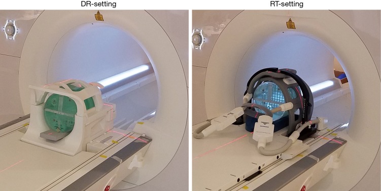
A large ACR MRI phantom was scanned on a 1.5T clinical MR-sim scanner (Magnetom Aera, Siemens Healthineers, Erlangen, Germany) with a 70 cm bore diameter using two different RF coil settings for acquisition. The first setting used a product volumetric head and neck coil (Head/Neck 20, Siemens Healthineers, Erlangen, Germany), named diagnostic radiological (DR)-setting hereafter. The second setting, called radiotherapy (RT)-setting, used two flexible 4-channel surface coils (Flex large 4, Siemens Healthineers, Erlangen, Germany) to wrap around the scanned subject using a third-party customized bi-lateral coil holder (CIVCO Medical Solutions, Coralville, Iowa, USA). A flat indexed couch-top (MRI Overlays, CIVCO Medical Solutions, Coralville, Iowa, USA) made of fiberglass with a foam core, having a three-pin Lok-Bar, was amounted and fixed on the scanner patient couch. Figure 1 Illustrates the ACR-phantom set-up under these two coil settings. The ACR phantom alignment was conducted using a well-calibrated external 3D laser system (DORADOnova MR3T, LAP GmbH Laser Applikationen, Luneburg, Germany) instead of the scanner integrated 2D laser.
Figure 1.
The ACR-phantom set-up under DR-setting with a volumetric head coil (left) and RT setting with two flexible coils (right). ACR, American College of Radiology; DR, diagnostic radiological; RT, radiotherapy.
The ACR phantom was carefully positioned and aligned for each scan session. A total of 9 scan sessions were conducted strictly following the ACR scanning instruction (7) under each setting. Standard scan protocol included a single slice sagittal localizer (spin echo, TR/TE =200/20 ms, FOV =25 cm, thickness =20 mm, NEX =1, Matrix =256×256, acquisition time =0:53), an 11-slice axial T1 series (spin echo, TR/TE =500/20 ms, FOV =25 cm, thickness =5 mm, gap =5 mm, NEX =1, Matrix =256×256, phase encoding direction: AP, receiver bandwidth =150 Hz/pixel, acquisition time =2:16) and an 11-slice axial T2 series (double-echo spin echo, TR/TE =2,000/20, 80 ms, FOV =25 cm, thickness =5 mm, gap =5 mm, NEX =1, Matrix =256×256, phase encoding direction: AP, receiver bandwidth =150 Hz/pixel, acquisition time =8:36). To comply with the real clinical RT simulation scan, prescan normalization (a scan option to mitigate the receive B1 field inhomogeneity and improve the image intensity uniformity under Siemens MRI platform) and 2D distortion correction were applied for image acquisition under both coil settings, although these prescriptions were not specified in the ACR scanning instruction.
Phantom image analysis and statistical analysis
The ACR phantom scan generated nine datasets under DR-setting and nine datasets under RT-setting. In each dataset, ACR phantom image acquired under DR-setting by sagittal localizer, T1 spin echo sequence and T2 spin echo sequence were referred as DR-localizer, DR-T1 and DR-T2 images, respectively. Correspondingly, those phantom images acquired under RT-setting were referred as RT-localizer, RT-T1 and RT-T2 images. Phantom image analysis was conducted using the scanner console by an MRI physicist A, strictly following the ACR test guidance. Seven quantitative measurements were conducted including geometric accuracy, high-contrast spatial resolution, slice thickness accuracy, slice position accuracy; image intensity uniformity, percent-signal ghosting and low-contrast object detectability. There was sufficient time interval between the image analyses on different image sets to avoid the potential bias due to the fresh memory of the last measurement results. The measurement results on RT-images were compared to those on DR-images using the Mann-Whitney U-test with a significance P value level of 0.05.
To assess the inter-observer agreement on phantom image analysis, another MRI physicist B conducted phantom image analyses on all datasets under RT-setting following the ACR test instructions, also using scanner console. MRI physicist B was blind to the measurement results of physicist A. Measurement agreements between two physicists were assessed using Bland-Altman (BA) analysis and intra-class correlation coefficient (ICC) (8,9).
Results
Phantom test results of RT-setting and comparison to DR-setting
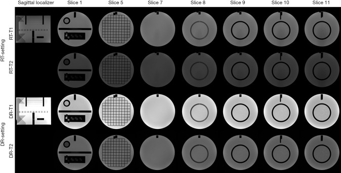
The measurement results under two settings were listed and compared in Table 1. The representative image series under RT-setting and DR-setting were illustrated in Figure 2.
Table 1. The measurement results (mean ± SD) under RT-setting and DR-setting.
| Test | Series | Slice location | Measurement index | RT (mean ± SD) | DR (mean ± SD) | Mann-Whitney (P value) |
|---|---|---|---|---|---|---|
| Geometric accuracy (mm) | T1 | Localizer | Phantom length | 147.8±0.2 | 147.9±0.2 | 0.22 |
| Slice 1 | Diameter (AP direction) | 190.7±0.3 | 190.7±0.2 | |||
| Slice 1 | Diameter (LR direction) | 191.4±0.2 | 191.0±0.2 | |||
| Slice 5 | Diameter (AP direction) | 190.7±0.5 | 190.6±0.3 | |||
| Slice 5 | Diameter (LR direction) | 191.1±0.2 | 190.5±0.3 | |||
| Slice 5 | Diameter (phantom’s UL to LR) | 190.8±0.3 | 190.6±0.2 | |||
| Slice 5 | Diameter (phantom’s UR to LL) | 191.0±0.2 | 190.5±0.2 | |||
| – | Mean diameter | 191.0±0.4 | 190.7±0.3 | <0.05 | ||
| Slice thickness accuracy (mm) | T1 | Slice 1 | Slice thickness | 5.2±0.1 | 5.1±0.1 | 0.34 |
| T2 | Slice 1 | Slice thickness | 5.0±0.1 | 5.0±0.1 | ||
| Slice position accuracy (mm) | T1 | Slice 1 | Bar difference | 1.4±0.7 | 0.7±1.0 | 0.41 |
| Slice 11 | Bar difference | –2.2±0.4 | –1.1±0.5 | |||
| T2 | Slice 1 | Bar difference | 1.5±0.2 | 0.8±0.9 | ||
| Slice 11 | Bar difference | –2.2±0.2 | –1.1±0.5 | |||
| Image intensity uniformity (%) | T1 | Slice 7 | PIU | 93.4±0.1 | 92.7±0.2 | <0.05 |
| T2 | Slice 7 | PIU | 93.3±0.2 | 93.1±0.3 | <0.05 | |
| Percent-signal ghosting | T1 | Slice 7 | Ghosting ratio | 0.0005±0.0003 | 0.0006±0.0003 | 0.39 |
| Low-contrast object detectability | T1 | Slices 8–11 | Total number of spoke | 31.0±1.3 | 36.9±0.8 | <0.05 |
| T2 | Slices 8–11 | Total number of spoke | 23.8±1.7 | 32.1±1.6 | <0.05 |
DR, diagnostic radiological; RT, radiotherapy; PIU, percent integral uniformity; LR, lower-right; UL, upper-left.
Figure 2.
The acquired T1 and T2 images under RT-setting and DR-setting, displayed in their corresponding default contrast level and windowing. Only the images used for image analysis are shown. RT, radiotherapy; DR, diagnostic radiological.
The geometric accuracy of the ACR phantom inside length (true value: 148.0 mm) measured on RT-localizer images was 147.8±0.2 mm (mean ± SD). The geometric accuracy of the measured ACR phantom inside diameter (true value: 190.0 mm) was 191.0±0.4 mm. As comparison, the corresponding geometric accuracy of the ACR phantom measured on DR-images was 147.9±0.2 mm (P=0.22) and 190.7±0.3 mm (P<0.05). The ACR recommended criterion on spatial accuracy was within ±2 mm of the true values so both settings passed. The measured diameter under RT-setting was significantly larger than that under DR-setting as revealed by Mann-Whitney U-test. This difference might be explained by the different display level and window used for measurement between two settings. However, it is worth noting that this mean difference of diameter accuracy was only 0.3 mm (much smaller than the ACR criterion of 2 mm), so might not much affect clinical RT use.
The spatial resolution for both RT-T1 and RT-T2 slice 1 images was 0.9 mm for upper-left (UL) hole arrays and 0.9 mm for lower-right (LR) hole arrays for eight datasets, and was 1.0 mm for one dataset, all passing the ACR criterion on spatial resolution of 1.0 mm or better. The spatial resolution for DR-images was 0.9 mm (UL) and 0.9 mm (LR), for all measurements.
The slice thickness measured on RT-T1 and RT-T2 images was 5.2±0.1 and 5.0±0.1 mm, not significantly different (P=0.34) from the corresponding values of 5.1±0.1 and 5.0±0.1 mm of DR images. All measurements were within the ACR criterion of 5.0±0.7 mm.
Slice position accuracy measured on RT-T1 was 1.4±0.7 mm (slice 1) and –2.2±0.4 mm (slice 11), and on RT-T2 was 1.5±0.2 mm (slice 1) and –2.2±0.2 mm (slice 11), better than the ACR criterion of the absolute value of 5mm or less. The measured slice position accuracy between two settings was not significantly different (P=0.41).
Image intensity uniformity calculated as percent integral uniformity (PIU) was 93.4%±0.1% (RT-T1) and 93.3%±0.2% (RT-T2) measured on RT-images, significantly higher (P<0.05) than 92.7%±0.2% (DR-T1) and 93.1%±0.3% (DR-T2) measured on DR-images, while both better than the ACR criterion of ≥87.5% for B0<3T.
Percent-signal ghosting ratio was 0.0005±0.0003 under RT-setting (RT-T1, slice 7), and 0.0006±0.0003 (DR-T1, slice 7) under DR-setting. Both well passed the ACR criterion of ≤0.025 and showed no significant difference (P=0.39).
For low-contrast object detectability, the total score of the complete spokes measured on RT-images was 31.0±1.3 (RT-T1) and 23.8±1.7 (RT-T2), better than the ACR criterion of ≥9 at B0<3T but significantly lower (P<0.05) than the corresponding scores of 36.9±0.8 (DR-T1) and 32.1±1.6 (DR-T2) under DR-setting. Figure 3 Illustrates the total score of the complete spokes measured on slices 8–11 displayed in the adjusted best contrast level and windowing under each setting.
Figure 3.
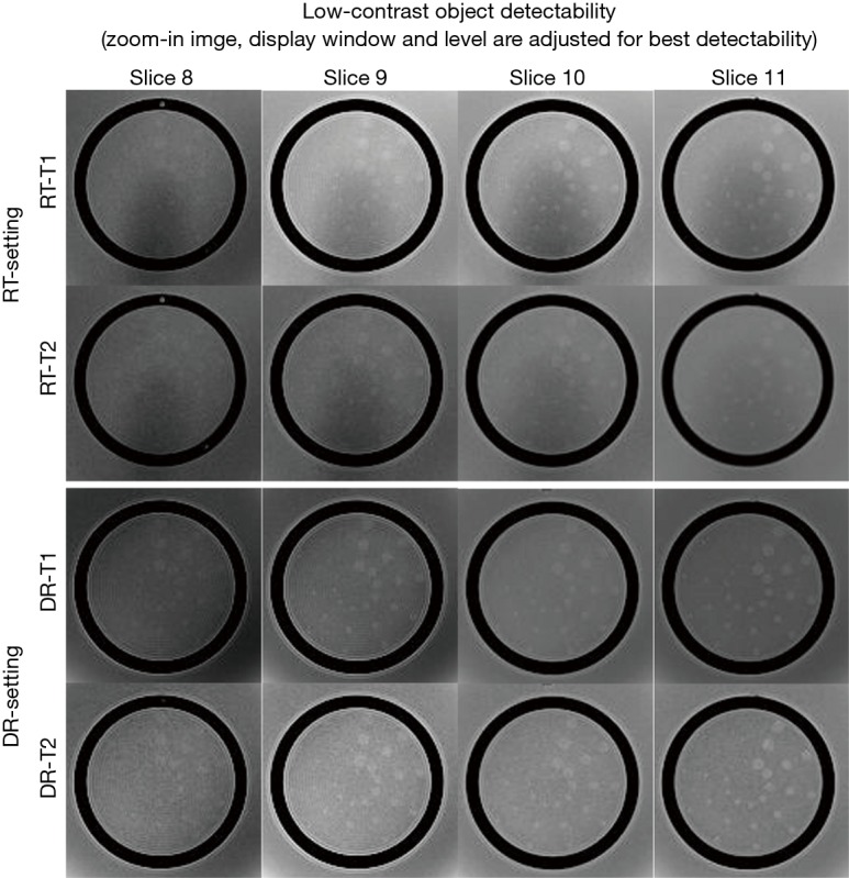
The zoom-in images of slices 8 to 11 used for low-contrast detectability. The contrast level and windowing are individually adjusted for best detectability. RT, radiotherapy; DR, diagnostic radiological.
Inter-observer agreement of ACR phantom test under RT-setting
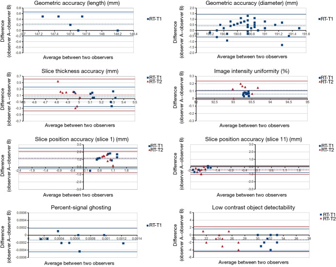
The results of BA analysis of inter-observer agreement under RT-setting were presented in Table 2 and Figure 4.
Table 2. The measurement bias and 95% limits of agreement calculated using the BA analysis of inter-observer agreement under RT-setting.
| Test | Series | Slice location | Measurement index | Bias | 95% limits of agreement |
|---|---|---|---|---|---|
| Geometric accuracy (mm) | T1 | Localizer | Phantom length | 0.2 | 0.4 |
| Slice 1 | Diameter (AP direction) | 0.0 | 1.3 | ||
| Slice 1 | Diameter (LR direction) | 0.5 | 1.0 | ||
| Slice 5 | Diameter (AP direction) | 0.4 | 1.2 | ||
| Slice 5 | Diameter (LR direction) | 0.5 | 0.7 | ||
| Slice 5 | Diameter (phantom’s UL to LR) | 0.5 | 0.7 | ||
| Slice 5 | Diameter (phantom’s UR to LL) | 0.6 | 0.7 | ||
| – | Mean diameter | 0.4 | 1.0 | ||
| Slice thickness accuracy (mm) | T1 | Slice 1 | Slice thickness | 0.1 | 0.3 |
| T2 | Slice 1 | Slice thickness | 0.1 | 0.5 | |
| Slice position accuracy (mm) | T1 | Slice 1 | Bar difference | 1.1 | 1.4 |
| Slice 11 | Bar difference | –0.3 | 0.5 | ||
| T2 | Slice 1 | Bar difference | 1.2 | 0.9 | |
| Slice 11 | Bar difference | –0.4 | 0.6 | ||
| Image intensity uniformity (%) | T1 | Slice 7 | PIU | 0.1 | 0.0 |
| T2 | Slice 7 | PIU | 0.1 | 0.1 | |
| Percent-signal ghosting | T1 | Slice 7 | Ghosting ratio | –0.0001 | 0.0003 |
| Low-contrast object detectability | T1 | Slices 8–11 | Total number of spoke | –1.3 | 2.9 |
| T2 | Slices 8–11 | Total number of spoke | –1.1 | 3.4 |
BA, Bland-Altman; RT, radiotherapy; PIU, percent integral uniformity; LR, lower-right; UL, upper-left.
Figure 4.
BA plots of inter-observer agreement on ACR phantom test under RT-setting. BA, Bland-Altman; ACR, American College of Radiology; RT, radiotherapy.
For geometric accuracy, BA analysis showed that the 95% limits of agreement of the phantom inside length and the inside diameter measurements were ±0.4 mm (inside length) and ±1.0 mm under RT setting. The measurement bias between two observers was 0.2 mm for inside length, and 0.4 mm for inside diameter. The bias and 95% limits of agreement were both much smaller than the 2 mm ACR criterion.
Two observers reached exactly the same reading of spatial resolution measurement, so thus no bias and complete agreement in BA analysis.
For slice thickness accuracy, the measurement bias was 0.1 mm for both RT-T1 and RT-T2. The 95% limit of agreement was ±0.3 mm, and ±0.5 mm for RT-T1 and RT-T2 respectively. All BA plot data points fell within the 95% limit of agreement.
For RT setting, the 95% limit of agreement for slice position accuracy was ±1.4 mm (RT-T1 slice 1), ±0.9 (RT-T2 slice 1), ±0.5 mm (RT-T1 slice 11) and ±0.6 mm (RT-T2 slice 11). The corresponding bias was 1.1, 1.2, –0.3 and –0.4 mm, respectively. Both 95% limit of agreement and bias were much smaller than ±5 mm of the ACR criterion.
Excellent inter-observer agreement was noted in the image uniformity assessment under RT-setting. The measurement bias was 0.1% for both RT-T1 and RT-T2. The corresponding 95% limit of agreement was approximately ±0% and ±0.1%, respectively.
The 95% limit of agreement for the percent-signal ghosting was ±0.0003 for RT-setting. The measurement bias was around –0.0001, very close to zero.
The low-contrast object detectability measurement bias was –1.3 (RT-T1), and -1.1 (RT-T2). The corresponding 95% limit of agreement was 2.9 and 3.4, respectively.
In terms of ICC, excellent inter-observer agreement (ICC >0.75) was achieved in six measurements of geometric accuracy (ICC >0.99), spatial resolution (ICC =1), slice position accuracy (ICC =0.81), image intensity uniformity (ICC =0.80), percent ghosting ratio (ICC =0.85) and low-contrast object detectability (ICC =0.89). A fair inter-observer agreement was noted in the slice thickness accuracy (ICC =0.42).
Discussion
There have been a number of publications of the ACR phantom test conducted on diagnostic MRI scanners (10-14) for diagnostic MRI QA/QC purpose, while the reports of ACR phantom test on dedicated MR-sim are still sparse (15). Our results showed that ACR phantom image acquired on a 1.5T dedicated MR-sim generally had sufficiently good image quality to pass all ACR recommended criteria, under a compromised flexible coil setting, thus fulfilled the basic requirements for clinical service. However, on the other hand, the ACR criteria are just indicative of a minimum level of performance of a well-functioning MRI system, but not necessarily suggest the fulfillment of advanced clinical application requirements. Our image analyses did reveal the significant underperformance of RT-setting primarily on low-contrast detectability. The relatively lower signal-to-noise ratio (SNR) of the RT-images accounts for this compromised low-contrast detectability. Although image SNR is not a measurement item in the ACR guidance, it could be estimated by using the recorded data for the calculation of percent-signal ghosting in T1 series. We calculated T1 image SNR by dividing the mean image intensity of the large region-of-interest (ROI) by the averaged image intensity of the left ROI and right ROI (left-right was along frequency encoding direction in our scan) in the slice 7 of T1 series. The image SNR was around 95±3.0 for RT-T1, considerably lower than that of 170.0±5.0 for DR-T1. The lower image SNR of RT-setting is mainly attributed to the sub-optimized flexible surface array coil performance compared to the volumetric head coil. As such, the lower image SNR associated with RT-setting might potentially compromise target and organ-at-risk (OAR) delineation in clinical practice, while yet to be further verified through in vivo imaging.
In terms of image intensity uniformity, RT-setting performed even better than DR-setting in a significance level, although the mean intensity uniformity value difference was small (<1%). This could be explained by the larger size of the coil element in the flexible coil than the size of the coil element in the head coil for DR-setting, and the increased distance between coil and phantom. On the other hand, it is worth noting that the use of technique to mitigate receive B1 inhomogeneity, such as prescan normalization, is essential for RT-setting to substantially increase image intensity uniformity. When prescan normalization was disabled (Figure 5), we found that the image intensity uniformity considerably reduced to 80.6%±2.6% and 80.2%%±3.1% for T1-RT and T2-RT, respectively, failed the ACR criterion of ≥87.5%. Meanwhile, prescan normalization did not compromise high-contrast image resolution in our experiments. Therefore, it is suggested to always enable prescan normalization for all simulation scans under RT-setting in clinical practice.
Figure 5.
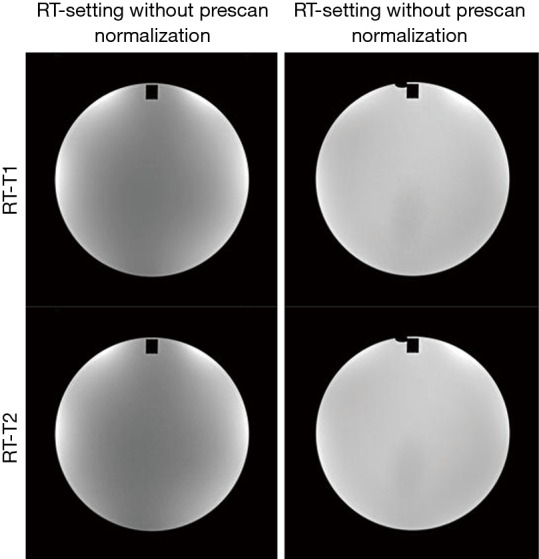
The images of slice 7 with and without prescan normalization under RT-setting. RT, radiotherapy.
In theory, other measurement items except for low-contrast detectability and image intensity uniformity should be less influenced by or independent of RF coil difference under two settings. High-contrast resolution might potentially be affected by SNR while our results showed that the highest 0.9 mm resolution could still be well resolved with the compromised SNR under RT-setting. A quite narrow receiver bandwidth of 150 Hz/pixel was used in this study. As MR image distortion theoretically increases with narrower receiver bandwidth, it is anticipated that better geometric fidelity could be achieved to meet the critical RT requirement when a larger receiver bandwidth is applied, although image SNR could be slightly reduced. It is worth noting that the difference of geometric accuracy should not be explained by the image distortion difference between two settings. Assumed that B0 homogeneity and gradient linearity were constant, it may mainly reflect the variability of the phantom positioning in each scan session and intra- or inter-observer disagreement. These two factors also account for the measurement differences of slice thickness accuracy and slice position accuracy between two settings. It was also noticed that the standard deviation of the slice position accuracy was larger under DR-setting than RT-setting. This might be explained by the fact that it is more difficult to consistently and precisely position the ACR phantom in the volumetric head coil due to its small and curved inner space. The use of a commercial ACR phantom holder or cradle may help to improve it.
BA analysis and inter-observer ICC results showed that the image quality of ACR MRI phantom under RT-setting was highly objective and reproducible. The largest inter-observer disagreement on slice thickness accuracy could be explained by the subjective placement of the length measurement line by the observers in the presence of scalloped or ragged ends of the two signal ramps.
This study has some limitations. First, the results in this study only assessed the image quality under one specific configuration suitable for RT purpose on a single MRI scanner. There are different customized RT-settings provided by vendors and research sites for different MRI scanner models. Even for a single MR scanner model, there could still be more than one RT-setting configuration. Although our results may serve as a reference baseline on a 1.5T MR-sim, the influence of different RT-settings on image quality and reproducibility needs to be individually investigated. This study was also limited in the small numbers of scans and only two observers. Since our results suggested that the results were highly constant and reproducible, we considered that the relatively small sample size could still represent a convincing result.
Finally, it is worth to point out that we did not intend to develop and suggest a QA protocol for MR-sim in this study by simply conducting the standard ACR phantom test under RT-setting. The results in this study could be used as a reference for MR-sim image quality assessment under RT-setting, but should not be interpreted as the passing criteria of accreditation or QA test for an MR-sim. It is highly desirable that a standardized QA protocol be developed for MR-sim, no matter using an ACR MRI phantom or not. At present, there are no well-acknowledged standardized QA protocols for MR-sim. Nonetheless, we believe that some components in the standard ACR phantom test should be of value for the future development of QA and/or QC protocols for MR-sim, because of its objectivity, standardization, repeatability and the wide availability of the phantom.
In conclusion, our study showed that sufficiently good image quality could be achieved using a flexible coil setting on a 1.5T MR-sim to pass the criteria of the standard ACR phantom test. Compared with DR-setting, RT-setting mainly under-performed in low-contrast object detectability because of its compromised image SNR. Standard ACR MRI phantom test under RT setting was overall highly reproducible and subject very little to inter-observer disagreement.
Acknowledgements
None.
Ethical Statement: This study was approved by the research committee and ethics board of Hong Kong Sanatorium & Hospital. This study did not involve human subject and no written informed consent was obtained.
Footnotes
Conflicts of Interest: The authors have no conflicts of interest to declare.
References
- 1.Khoo VS, Dearnaley DP, Finnigan DJ, Padhani A, Tanner SF, Leach MO. Magnetic resonance imaging (MRI): considerations and applications in radiotherapy treatment planning. Radiother Oncol 1997;42:1-15. 10.1016/S0167-8140(96)01866-X [DOI] [PubMed] [Google Scholar]
- 2.Schmidt MA, Payne GS. Radiotherapy planning using MRI. Phys Med Biol 2015;60:R323-61. 10.1088/0031-9155/60/22/R323 [DOI] [PMC free article] [PubMed] [Google Scholar]
- 3.Accreditation of Advanced Diagnostic Imaging Suppliers. Available online: https://www.cms.gov/Medicare/Provider-Enrollment-and-Certification/SurveyCertificationGenInfo/Accreditation-of-Advanced-Diagnostic-Imaging-Suppliers.html, accessed June, 2016.
- 4.MRI Accreditation. The American College of Radiology, Reston, VA. Available online: http://www.acr.org/quality-safety/accreditation/mri, accessed June, 2016.
- 5.Phantom Test Guidance for the ACR MRI Accreditation Program. The American College of Radiology, Reston, VA. Available online: http://www.acraccreditation.org/~/media/ACRAccreditation/Documents/MRI/LargePhantomGuidance.pdf?la=en, accessed June 2016.
- 6.Liney GP, Moerland MA. Magnetic resonance imaging acquisition techniques for radiotherapy planning. Semin Radiat Oncol 2014;24:160-8. 10.1016/j.semradonc.2014.02.014 [DOI] [PubMed] [Google Scholar]
- 7.Site Scanning Instructions for Use of the MR Phantom for the ACRTM MRI Accreditation Program. The American College of Radiology, Reston, VA. Available online: http://www.acraccreditation.org/~/media/ACRAccreditation/Documents/MRI/LargePhantomInstructions.pdf?la=en, accessed June, 2016.
- 8.Bland JM, Altman DG. Statistical methods for assessing agreement between two methods of clinical measurement. Lancet 1986;1:307-10. 10.1016/S0140-6736(86)90837-8 [DOI] [PubMed] [Google Scholar]
- 9.Shrout PE, Fleiss JL. Intraclass correlations: uses in assessing rater reliability. Psychol Bull 1979;86:420-8. 10.1037/0033-2909.86.2.420 [DOI] [PubMed] [Google Scholar]
- 10.Davids M, Zöllner FG, Ruttorf M, Nees F, Flor H, Schumann G, Schad LR; IMAGEN Consortium. Fully-automated quality assurance in multi-center studies using MRI phantom measurements. Magn Reson Imaging 2014;32:771-80. 10.1016/j.mri.2014.01.017 [DOI] [PubMed] [Google Scholar]
- 11.Ihalainen TM, Lönnroth NT, Peltonen JI, Uusi-Simola JK, Timonen MH, Kuusela LJ, Savolainen SE, Sipilä OE. MRI quality assurance using the ACR phantom in a multi-unit imaging center. Acta Oncol 2011;50:966-72. 10.3109/0284186X.2011.582515 [DOI] [PubMed] [Google Scholar]
- 12.Kaljuste D, Nigul M. Evaluation of the ACR MRI phantom for quality assurance tests of 1.5 T MRI scanners in Estonian hospitals. Proceedings of the Estonian Academy of Sciences 2014;63:240 10.3176/proc.2014.3.06 [DOI] [Google Scholar]
- 13.Panych LP, Chiou JY, Qin L, Kimbrell VL, Bussolari L, Mulkern RV. On replacing the manual measurement of ACR phantom images performed by MRI technologists with an automated measurement approach. J Magn Reson Imaging 2016;43:843-52. 10.1002/jmri.25052 [DOI] [PubMed] [Google Scholar]
- 14.Chen CC, Wan YL, Wai YY, Liu HL. Quality assurance of clinical MRI scanners using ACR MRI phantom: preliminary results. J Digit Imaging 2004;17:279-84. 10.1007/s10278-004-1023-5 [DOI] [PMC free article] [PubMed] [Google Scholar]
- 15.Sandgren K. Development of a Quality Assurance Strategy for Magnetic Resonance Imaging in Radiotherapy. Umeå University 2015. Available online: http://umu.diva-portal.org/smash/record.jsf?pid=diva2%3A839470&dswid=6746


